EP3311901A2 - Folie mit einem aus einem thermoplastischen kunststoffmaterial bestehenden flächenelement sowie verfahren zur herstellung der folie - Google Patents
Folie mit einem aus einem thermoplastischen kunststoffmaterial bestehenden flächenelement sowie verfahren zur herstellung der folie Download PDFInfo
- Publication number
- EP3311901A2 EP3311901A2 EP17001658.8A EP17001658A EP3311901A2 EP 3311901 A2 EP3311901 A2 EP 3311901A2 EP 17001658 A EP17001658 A EP 17001658A EP 3311901 A2 EP3311901 A2 EP 3311901A2
- Authority
- EP
- European Patent Office
- Prior art keywords
- film
- filter
- coating
- perforation
- surface element
- Prior art date
- Legal status (The legal status is an assumption and is not a legal conclusion. Google has not performed a legal analysis and makes no representation as to the accuracy of the status listed.)
- Granted
Links
Images




Classifications
-
- B—PERFORMING OPERATIONS; TRANSPORTING
- B01—PHYSICAL OR CHEMICAL PROCESSES OR APPARATUS IN GENERAL
- B01D—SEPARATION
- B01D36/00—Filter circuits or combinations of filters with other separating devices
- B01D36/001—Filters in combination with devices for the removal of gas, air purge systems
-
- B—PERFORMING OPERATIONS; TRANSPORTING
- B01—PHYSICAL OR CHEMICAL PROCESSES OR APPARATUS IN GENERAL
- B01D—SEPARATION
- B01D29/00—Filters with filtering elements stationary during filtration, e.g. pressure or suction filters, not covered by groups B01D24/00 - B01D27/00; Filtering elements therefor
- B01D29/11—Filters with filtering elements stationary during filtration, e.g. pressure or suction filters, not covered by groups B01D24/00 - B01D27/00; Filtering elements therefor with bag, cage, hose, tube, sleeve or like filtering elements
- B01D29/114—Filters with filtering elements stationary during filtration, e.g. pressure or suction filters, not covered by groups B01D24/00 - B01D27/00; Filtering elements therefor with bag, cage, hose, tube, sleeve or like filtering elements arranged for inward flow filtration
-
- B—PERFORMING OPERATIONS; TRANSPORTING
- B01—PHYSICAL OR CHEMICAL PROCESSES OR APPARATUS IN GENERAL
- B01D—SEPARATION
- B01D29/00—Filters with filtering elements stationary during filtration, e.g. pressure or suction filters, not covered by groups B01D24/00 - B01D27/00; Filtering elements therefor
- B01D29/50—Filters with filtering elements stationary during filtration, e.g. pressure or suction filters, not covered by groups B01D24/00 - B01D27/00; Filtering elements therefor with multiple filtering elements, characterised by their mutual disposition
- B01D29/52—Filters with filtering elements stationary during filtration, e.g. pressure or suction filters, not covered by groups B01D24/00 - B01D27/00; Filtering elements therefor with multiple filtering elements, characterised by their mutual disposition in parallel connection
- B01D29/54—Filters with filtering elements stationary during filtration, e.g. pressure or suction filters, not covered by groups B01D24/00 - B01D27/00; Filtering elements therefor with multiple filtering elements, characterised by their mutual disposition in parallel connection arranged concentrically or coaxially
-
- B—PERFORMING OPERATIONS; TRANSPORTING
- B01—PHYSICAL OR CHEMICAL PROCESSES OR APPARATUS IN GENERAL
- B01D—SEPARATION
- B01D35/00—Filtering devices having features not specifically covered by groups B01D24/00 - B01D33/00, or for applications not specifically covered by groups B01D24/00 - B01D33/00; Auxiliary devices for filtration; Filter housing constructions
- B01D35/02—Filters adapted for location in special places, e.g. pipe-lines, pumps, stop-cocks
- B01D35/027—Filters adapted for location in special places, e.g. pipe-lines, pumps, stop-cocks rigidly mounted in or on tanks or reservoirs
- B01D35/0273—Filtering elements with a horizontal or inclined rotation or symmetry axis submerged in tanks or reservoirs
-
- B—PERFORMING OPERATIONS; TRANSPORTING
- B01—PHYSICAL OR CHEMICAL PROCESSES OR APPARATUS IN GENERAL
- B01D—SEPARATION
- B01D35/00—Filtering devices having features not specifically covered by groups B01D24/00 - B01D33/00, or for applications not specifically covered by groups B01D24/00 - B01D33/00; Auxiliary devices for filtration; Filter housing constructions
- B01D35/06—Filters making use of electricity or magnetism
-
- B—PERFORMING OPERATIONS; TRANSPORTING
- B01—PHYSICAL OR CHEMICAL PROCESSES OR APPARATUS IN GENERAL
- B01D—SEPARATION
- B01D39/00—Filtering material for liquid or gaseous fluids
- B01D39/14—Other self-supporting filtering material ; Other filtering material
- B01D39/16—Other self-supporting filtering material ; Other filtering material of organic material, e.g. synthetic fibres
- B01D39/1692—Other shaped material, e.g. perforated or porous sheets
-
- B—PERFORMING OPERATIONS; TRANSPORTING
- B01—PHYSICAL OR CHEMICAL PROCESSES OR APPARATUS IN GENERAL
- B01D—SEPARATION
- B01D2239/00—Aspects relating to filtering material for liquid or gaseous fluids
- B01D2239/04—Additives and treatments of the filtering material
Definitions
- the invention relates to a film with a surface element made of a thermoplastic material. Furthermore, the invention relates to a method for producing a film having permanent magnetic properties, to a filter cartridge for transmission oil filtration, which is provided with a film having permanent magnetic property, as well as to a filter element for the filtration of fluids, which contains a permanent magnetic property film.
- the invention has the object to provide a permanent magnetic device available, which is particularly simple and inexpensive to produce and in fluid systems of various kinds with advantage universally usable.
- the invention provides a film with an existing of a thermoplastic material surface element, which has permanent magnetic property.
- a permanent magnetic device can not only produce rational and inexpensive, but adapt as a flexible surface element particularly easy to the most diverse applications of applications in fluid circuits of various kinds and integrate into respective systems, because the flexibility as a film connection to structures or Substrates of different geometry allows.
- the magnetic film according to the invention is therefore suitable for universal use.
- the permanent magnetic property is achieved in that the film is provided on at least one side in at least one subregion with a permanent magnetic property having coating.
- the arrangement may advantageously be such that the permanent-magnetic coating is applied on both sides over part of the surface or over the entire surface.
- the film can be provided with perforation in at least one surface area.
- the accumulation of metallic particles serving magnetic device the film can therefore be arranged advantageously directly in the flow path of a respective fluid circuit.
- a perforation in the form of a pattern deviating from the circular shape, preferably oval holes is provided.
- an optimal compromise of structural strength and fluid permeability is achieved by oval or elliptical shape of fluid passage openings.
- a material relief is achieved with voltage or force introduction and thus an increased tensile strength.
- the surface element carrying the coating may consist of a polyethylene (PE), polypropylene (PP) or polyamide (PA), polyethylene terephthalate (PET) preferably being provided as the plastic material.
- PE polyethylene
- PP polypropylene
- PA polyamide
- PET polyethylene terephthalate
- the arrangement is advantageously made in such a way that the magnetic coating produces a permanent magnetic field with a polarity running transversely to the broad sides of the film.
- an additional field reinforcement results at the edge of the holes forming the respective perforation.
- the invention provides for a surface element, which is preferably made of PET, a coating which is formed from a paint-like material to which magnetizable particles are added, wherein particles of boron neodymium are preferably added to the coating material.
- the material of the coating can be applied by doctoring, roller application or digital printing.
- the roller application can be carried out in a particularly advantageous manner by a web-fed rotary printing process (flexographic printing) with corona pretreatment of the surface element.
- the curing of the applied coating can be done by a drying process. With particular advantage, however, a curing is carried out by means of UV light.
- the magnetization for generating the permanent magnetic field with transverse to the broad sides of the film polarity is advantageously carried out after performing the other manufacturing steps, for example by passing the finished film through the field of an electromagnet or let fall through.
- the subject of the invention is also a filter cartridge for transmission oil filtration, which is insertable into the bottom region of a transmission housing or an oil pan, at least one filter element and provided with a permanent magnetic property having film according to one of claims 1 to 8.
- the so available for the filter cartridge and metallic particles accumulating permanent magnet device reduces the particle load of the respective filter element of the filter cartridge and increases the reliability at longer operating times.
- the arrangement can advantageously be such that, in the case of a filter cartridge with an outer shell, the film is arranged on the inside and / or outside, seen in the flow direction of the filtration, upstream of the inflow side of the filter element.
- the outer shell has the shape of a flat shell with a shell bottom which is closed except for a fluid-permeable inflow region
- the magnetic foil according to the invention which forms the inflow region with its perforation.
- the film according to the invention not only forms a large-area wall element of the casing, but also provides a large contact surface for the gear oil in this form, so that effective particle separation is ensured.
- the film according to the invention can also form part of the filter material of the respective filter element of the filter cartridge, for example by forming an additional layer in a multilayer filter material.
- the Fig. 1 shows a partial surface area of an embodiment of the magnetic film 1 according to the invention with a flat sheet-forming surface element 3, which consists of a plastic film suitable and conventional material.
- a flat sheet-forming surface element 3 which consists of a plastic film suitable and conventional material.
- PET polyethylene terephthalate
- the surface element 3 has a thickness of 0.2 mm in the example shown. Depending on the conditions of use, far lower film thicknesses or even greater thicknesses of 1 mm or more may be considered.
- the material of the surface element 3 is preferably stretched biaxially to increase the structural strength.
- the film 1 is designed to be fluid-permeable over the entire surface and provided with a perforation 24 for this purpose.
- the holes 7 may be formed in the surface element 3 in various ways, for example by punching or lasing.
- the surface element 3 may be provided with the perforation 24 only in selected surface areas in order to form passages defined by a fluid for the flow through the film 1. If a flat flow or contacting of the film 1 is provided with fluid, the perforation 24 of the surface element 3 may be omitted.
- this has on at least one side, when in Fig. 1 shown example on the underlying page, a coating 5 of the surface element 3.
- This is in a layer thickness which can be between 1 .mu.m and more than 200 .mu.m , formed from a paint-like material, such as a screen printing ink or the like, and applied by means of a coating method, such as doctoring, roller application or digital printing.
- the roller application can be carried out in the form of a web-fed rotary printing process (flexographic printing), wherein a corona pretreatment of the surface element 3 is provided.
- the coating 5 can be applied over its entire surface on both sides of the surface element 3.
- magnetisable particles are added to the coating material.
- Particles of Boreisenneodym are provided with advantage, with which a high magnetic field strength can be achieved.
- the coating is cured by means of a drying process. With little time, this can be done in a rational way by means of UV light.
- the magnetization as a final step of the manufacturing process takes place after the curing of the coating 5 by the action of an external magnetic field. For this purpose, the so far completed film product is passed through the field of a solenoid device, for example by letting the film 1 fall through the field.
- the film 1 is oriented relative to the electromagnetic field so that the magnetic particles of the coating 5 are magnetized with perpendicular to the broad sides of the film 1 polarity. This line of force leads at the edges of the holes 7 to a field compression and high magnetic force effect of the film first
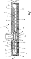
- the Fig. 2 to 6 show an example of the use of the magnetic film 1 according to the invention as a permanent magnet device, which is used in a filter cartridge for transmission oil filtration for the deposition of metallic particles from the transmission oil, which is provided to the converter of an (not shown) automatic transmission.
- the filter cartridge shown in the drawing has an outer shell 2 which is injection molded from a plastic material and (s. Fig. 2 ) has the shape of a flat rectangular cuboid with rounded corners 4. On the flat top 6 is located centrally between the long sides, but one of the narrow sides closer than the other narrow side, a Saugan gleichstutzen 8.
- an outer edge 10 which, like the top 6, is planar and in the shown embodiment has a vertical height which corresponds to about one tenth of the length of the long sides.
- an inner peripheral edge 12 which extends at a distance within the outer edge 10 and parallel to this, in the shell 2, an inner shell which is open at the bottom and in which, s.
- Fig. 3 two filter elements 16 and 18 are received, which are intended for operation as a suction filter device.
- the Fig. 4 shows the view from below into the open shell without filter elements 16, 18 installed therein, while the Fig. 5 the shell closed by a shell bottom 20 shows.
- This shell bottom 20 is formed by the film 1 according to the invention, which is welded to a peripheral edge strip 22 of the inner peripheral edge 12.
- the film 1 has the perforation 24 only in a partial area. More specifically, the perforation 24 extends in a parallel side edge strip which, like Fig. 3 shows, parallel to the narrow sides of the shell runs, in a position which is aligned with the connecting piece 8 and which forms an inflow region of the filter cartridge for the filtration operation.
- a degassing device is arranged, which forms a circumferentially extending rim 26 which projects beyond the underside of the shell bottom 20 and upon installation of the filter cartridge on the bottom portion of the associated gear housing (not shown) stands up and in dipping the oil sump.
- the filter element 16 is a coarse filter and the filter element 18 is a fine filter.
- the axial length of the filter element 18 is about 2.8 times the filter element 16.
- the filter elements 16, 18 have as a filter material on a multi-layer filter mat surrounding an inner filter cavity 30 and 32 respectively and between end caps 34 and 36 attached to shoulders 38, which, see FIG.
- Fig. 3 are formed on the inside of the top, are welded to the shell 2.
- the inventive Foil 1 as an additional layer in the pleated layer composite of the multilayer filter material 48 of the filter elements 16, 18 to be folded with the magnetic film 1 is arranged on the upstream side of the material 48 and forms an additional permanent magnet device within the filter cartridge.
- the connecting piece 8 is connected to a suction oil pump of the transmission.
- the oil passes over the perforation region 24 of the film 1 forming the shell bottom 20 in flow chambers 40 (FIG. Fig. 4 ), which are formed between a partition 42 and strips 44, to which latter the film 1 of the shell bottom 20 rests. From the spaces 40, the oil passes, as with arrows 46 ( Fig. 3
- To form the flow paths to the inflow to the outside of the filter elements 16, 18 is between the outside of the filter material 48 and the adjacent wall of outer shell 2 and the shell bottom 20 forming film 1 each one Free space or a flat drainage layer 50 in the form of a fluid-permeable foam material.
- the filter material 48 While in conventional filter elements having a multilayer filter material, which preferably pleats In the present filter elements 16, 18, the filter material 48 is flattened so to speak, ie, the inner filter cavity 30 and 32, as well as the outside of the filter material 48, have the shape of a very shallow oval, wherein the outside of the filter material 48 extends substantially over the entire width of the narrow side of the filter cartridge. With a large available filter surface, therefore, a flat construction of the outer shell 2 can be realized. With the arrangement of drainage layers 50 on the outside of the filter material 48, it is possible to form the outer shell 2 from a flexible film, such as a polyamide such as PA6, instead of a solid plastic material. Since the drainage layers 50 provide the required fluid paths, the outer shell 2 and the shell bottom 20 can directly conform to the inner contour, so that a particularly low overall height can be realized for the filter cartridge.
- a flexible film such as a polyamide such as PA6
- FIG. 6 schematically further simplified representation shows the Fig. 6 a second embodiment of the filter cartridge, in which only the coarse filter forming the filter element 16 as a suction filter and the fine filter forming the filter element 18 is operable as a return filter.
- the connecting piece 8 has two separate fluid paths, one of which forms a suction pump connection 54 and the other a return connection 56.
- the filter element 16 flows through the perforation region 24 of the tray bottom 20 forming film 1 as a coarse filter to the pump port 54 through.
- the fine filter element forming the filter element 18 is operated via the return port 56 as a return filter, wherein, as in Fig. 6 shown with Einströmpfeil 58, the unfiltered material flows to the inner filter cavity 32.
- the filtrate exiting on the outside of the filter element 18, like the filtrate of the coarse filter passes directly to the pump connection 54, s. Arrow 60 from Fig. 6 ,
- the film 1 may be attached to the outer shell 2 on the outside, as shown in FIG Fig. 4 and 5 is shown, where the film 1 is attached in the form of a tape with external coating 5 at the outer edge 10 along the long sides and the narrow sides of the shell 2.
- a film 1 on its visible coating 5 could also be provided with a decorative pattern or mark, such as a label.
- the film according to the invention can form part of a filter element for any desired use in different fluid circuits, for example in filter elements of the type described in US Pat DE 10 2011 122 348 A1 shown genus, which have a filter material in the form of a composite of several star-folded, pleated layers, wherein the film 1 according to the invention can be folded as a permanent magnet device on the upstream side in the layer composite as an additional layer.
Landscapes
- Chemical & Material Sciences (AREA)
- Chemical Kinetics & Catalysis (AREA)
- Engineering & Computer Science (AREA)
- Water Supply & Treatment (AREA)
- Treatments Of Macromolecular Shaped Articles (AREA)
- Laminated Bodies (AREA)
- Separation Using Semi-Permeable Membranes (AREA)
- General Details Of Gearings (AREA)
- Filtering Materials (AREA)
Abstract
Description
- Die Erfindung betrifft eine Folie mit einem aus einem thermoplastischen Kunststoffmaterial bestehenden Flächenelement. Ferner bezieht sich die Erfindung auf ein Verfahren zum Herstellen einer permanentmagnetische Eigenschaft aufweisenden Folie, auf eine Filterkassette für Getriebeölfiltration, die mit einer permanentmagnetische Eigenschaft aufweisenden Folie versehen ist, sowie auf ein Filterelement für die Filtration von Fluiden, das eine permanentmagnetische Eigenschaft aufweisende Folie enthält.
- Die Betriebssicherheit technischer Anlagen, die Fluidkreisläufe aufweisen, in denen funktionale Fluide, wie Hydraulikmedien, Schmiermittel oder dergleichen, zirkulieren, hängt in hohem Maße von der einwandfreien Beschaffenheit des Fluids ab. Insbesondere, wenn es sich um hochwertige Anlagen handelt, bei denen Betriebsstörungen oder Ausfälle zu hohen wirtschaftlichen Schäden führen, ist es daher Stand der Technik, Einrichtungen zur Pflege der Fluide vorzusehen. Beispielsweise zeigt die
DE 10 2007 023 641 B4 eine Filterkassette, die für die Pflege des dem Wandler eines Automatikgetriebes zur Verfügung stehenden Getriebeöls vorgesehen ist. Neben Filtereinrichtungen für die Abreinigung von Verschmutzungen sind bei Anlagen, bei denen es zu einer Belastung des Fluids mit metallischen Partikeln, beispielsweise durch mechanischen Abrieb, kommen kann, häufig auch mit dem Fluid in Kontakt stehende Magneteinrichtungen vorgesehen, um metallische Partikel durch Anhaften abzusondern. - Ausgehend von diesem Stand der Technik stellt sich die Erfindung die Aufgabe, eine permanentmagnetische Einrichtung zur Verfügung zu stellen, die besonders einfach und kostengünstig herstellbar sowie bei Fluidsystemen verschiedenster Art mit Vorteil universell verwendbar ist.
- Erfindungsgemäß ist diese Aufgabe durch eine Folie gelöst, die die Merkmale des Patentanspruchs 1 in seiner Gesamtheit aufweist.
- Gemäß dem Patentanspruch 1 sieht die Erfindung eine Folie mit einem aus einem thermoplastischen Kunststoffmaterial bestehenden Flächenelement vor, die permanentmagnetische Eigenschaft aufweist. In der Bauform als Folie lässt sich eine permanentmagnetische Einrichtung nicht nur rationell und kostengünstig herstellen, sondern als flexibles Flächenelement besonders einfach an die unterschiedlichsten Gegebenheiten betreffender Einsatzzwecke bei Fluidkreisläufen unterschiedlichster Art anpassen und in jeweilige Anlagen integrieren, weil die Flexibilität als Folie die Verbindung mit Strukturen oder Substraten unterschiedlichster Geometrie ermöglicht. Die erfindungsgemäße Magnetfolie eignet sich daher für universelle Verwendung.
- Bei vorteilhaften Ausführungsbeispielen ist die permanentmagnetische Eigenschaft dadurch erreicht, dass die Folie auf zumindest einer Seite in zumindest einem Teilbereich mit einer permanentmagnetische Eigenschaft aufweisenden Beschichtung versehen ist.
- Je nach Verwendungszweck kann die Anordnung mit Vorteil so getroffen sein, dass die permanentmagnetische Beschichtung auf beiden Seiten teilflächig oder vollflächig aufgebracht ist.
- Die Folie kann in zumindest einem Flächenbereich mit einer Perforation versehen sein. Als fluiddurchlässige, der Ansammlung von metallischen Partikeln dienende Magneteinrichtung lässt sich die Folie daher in vorteilhafter Weise unmittelbar im Strömungsweg eines betreffenden Fluidkreislaufs anordnen.
- Bei besonders vorteilhaften Ausführungsformen ist eine Perforation in Form eines Musters aus von der Kreisform abweichenden, vorzugsweise ovalen Löchern vorgesehen. Wie in dem Dokument
WO 2013/050176 A1 für ein Kunststoff-Folienmaterial beschrieben, ist durch ovale oder ellipsenförmige Form von Fluiddurchlassöffnungen ein optimaler Kompromiss aus Strukturfestigkeit und Fluiddurchlässigkeit erreicht. Im Vergleich zu einer Perforation in Form eines Musters aus runden Löchern, wird eine Materialentlastung bei Spannungs- oder Krafteinleitung und damit eine erhöhte Zugfestigkeit erreicht. - Mit besonderem Vorteil kann das die Beschichtung tragende Flächenelement aus einem Polyethylen (PE), Polypropylen (PP) oder Polyamid (PA) bestehen, wobei bevorzugt Polyethylenterephthalat (PET) als Kunststoffmaterial vorgesehen ist.
- Für eine besonders effektive Anlagerung metallischer Partikel ist die Anordnung vorteilhafterweise derart getroffen, dass durch die magnetische Beschichtung ein Permanentmagnetfeld mit zu den Breitseiten der Folie quer verlaufender Polarität erzeugt ist. Bei dieser Ausrichtung des Magnetfeldes mit durch die Fläche verlaufenden Kraftlinien ergibt sich eine zusätzliche Feldverstärkung am Rand der die jeweilig Perforation bildenden Löcher.
- Gegenstand der Erfindung ist auch ein Verfahren zum Herstellen einer permanentmagnetische Eigenschaft aufweisenden Folie, wobei das Verfahren die im Patentanspruch 9 angegebenen Schritte aufweist, nämlich:
- Bereitstellen eines Flächenelements aus einem thermoplastischen Kunststoffmaterial;
- Aufbringen einer magnetisierbare Partikel enthaltenden Beschichtung auf zumindest einen Teilbereich mindestens einer Seite des Flächenelements;
- Aushärten der Beschichtung und
- Magnetisieren durch Einwirkung eines Magnetfeldes.
- Danach sieht die Erfindung für ein Flächenelement, das vorzugsweise aus PET besteht, eine Beschichtung vor, die aus einem lackartigen Material, dem magnetisierbare Partikel zugesetzt sind, gebildet wird, wobei dem Beschichtungsmaterial vorzugsweise Partikel aus Boreisenneodym zugesetzt werden. Das Material der Beschichtung kann durch Rakeln, Walzenauftrag oder Digitaldruck aufgebracht werden. Der Walzenauftrag kann in besonders vorteilhafter Weise durch ein Rollenrotationsdruckverfahren (Flexodruck) mit Koronavorbehandlung des Flächenelements durchgeführt werden. Das Aushärten der aufgebrachten Beschichtung kann durch ein Trocknungsverfahren erfolgen. Mit besonderem Vorteil wird jedoch ein Aushärten mittels UV-Licht durchgeführt. Die Magnetisierung zum Erzeugen des Permanentmagnetfeldes mit zu den Breitseiten der Folie quer verlaufender Polarität wird vorteilhafterweise nach Durchführen der übrigen Herstellschritte durchgeführt, beispielsweise indem man die fertige Folie durch das Feld eines Elektromagneten hindurchführt oder hindurchfallen lässt.
- Gemäß dem Patentanspruch 20 ist Gegenstand der Erfindung auch eine Filterkassette für Getriebeölfiltration, die in den Bodenbereich eines Getriebegehäuses oder einer Ölwanne einsetzbar ist, zumindest ein Filterelement enthält und mit einer permanentmagnetische Eigenschaft aufweisenden Folie gemäß einem der Ansprüche 1 bis 8 versehen ist. Die für die Filterkassette so zur Verfügung stehende und metallische Partikel ansammelnde Permanentmagneteinrichtung verringert die Partikelbelastung des jeweiligen Filterelements der Filterkassette und erhöht die Betriebssicherheit bei längeren Betriebslaufzeiten.
- Die Anordnung kann mit Vorteil so getroffen sein, dass bei einer Filterkassette mit einer Außenhülle die Folie an dieser innenseitig und/oder außenseitig, in Strömungsrichtung der Filtration gesehen vor der Anströmseite des Filterelements, angeordnet ist.
- Bei einer Filterkassette, bei der die Außenhülle die Form einer flachen Schale mit einem bis auf einen fluiddurchlässigen Einströmbereich geschlossenen Schalenboden aufweist, kann dieser durch die erfindungsgemäße Magnetfolie gebildet sein, die mit ihrer Perforation den Einströmbereich bildet. Die erfindungsgemäße Folie bildet dadurch nicht nur ein großflächiges Wandelement der Hülle, sondern stellt in dieser Form für das Getriebeöl auch eine große Kontaktfläche zur Verfügung, so dass eine effektive Partikelabscheidung gewährleistet ist.
- Mit durchgehender Perforation kann die erfindungsgemäße Folie auch Bestandteil des Filtermaterials des jeweiligen Filterelements der Filterkassette bilden, beispielsweise indem es bei einem mehrlagigen Filtermaterial eine Zusatzlage bildet.
- Gemäß dem Patentanspruch 24 ist Gegenstand der Erfindung auch ein Filterelement für die Filtration von Fluiden, mit einem Filtermaterial, das aus mehreren flächig miteinander verbundenen, mediendurchlässigen Lagen gebildet ist, wobei der Lagenverbund zur Bildung eines plissierten Verlaufs sterngefaltet ist und wobei in den sterngefalteten Lagenverbund eine Folie gemäß einem der Ansprüche 1 bis 8 mit eingefaltet ist. Filterelemente mit mehrlagigem, sterngefaltetem Filtermaterial sind Stand der Technik, vergleiche beispielsweise
DE 10 2011 122 348 A1 . Die erfindungsgemäße Folie kann mit Vorteil bei einem derartigen Filterelement beispielsweise als anströmseitig gelegene Stützlage mit eingefaltet sein.
Nachstehend ist die Erfindung anhand der Zeichnung im Einzelnen erläutert.
Es zeigen: - Fig. 1
- eine stark vergrößert, abgebrochen und angeschnitten gezeichnete perspektivische Schrägansicht eines Flächenabschnitts der erfindungsgemäßen Magnetfolie;
- Fig. 2
- eine perspektivische Schrägansicht einer Filterkassette für Getriebeölfiltration;
- Fig. 3
- einen schematisch vereinfacht gezeichneten Vertikalschnitt der Filterkassette mit zentral verlaufender Schnittebene;
- Fig. 4
- eine in perspektivischer Schrägansicht gezeichnete Unteransicht der Schale der Außenhülle der Filterkassette, wobei der Schalenboden weggelassen ist;
- Fig. 5
- eine Unteransicht der Filterkassette; und
- Fig. 6
- eine in Richtung der Langseiten aufgeschnittene perspektivische Schrägansicht der Filterkassette, gesehen auf die Unterseite und ohne Entgasungseinrichtung.
- Die
Fig. 1 zeigt einen Teilflächenbereich eines Ausführungsbeispiels der erfindungsgemäßen Magnetfolie 1 mit einem eine flache Folienbahn bildenden Flächenelement 3, das aus einem für Kunststofffolien geeigneten und üblichen Material besteht. Beim vorliegenden Beispiel ist hierfür Polyethylenterephthalat (PET) vorgesehen. Das Flächenelement 3 besitzt beim gezeigten Beispiel eine Dicke von 0,2 mm. Je nach Einsatzbedingungen kommen weit geringere Folienstärken oder auch größere Dicken von 1 mm oder mehr in Betracht. Vor der Weiterbehandlung wird das Material des Flächenelements 3 vorzugsweise zur Erhöhung der Strukturfestigkeit biaxial gereckt. Bei dem inFig. 1 gezeigten Ausführungsbeispiel ist die Folie 1 vollflächig fluiddurchlässig ausgebildet und hierfür mit einer Perforation 24 versehen. Diese ist durch ein Lochmuster aus ellipsenförmigen Löchern 7 gebildet, die inFig. 1 nur teilweise beziffert sind und in zueinander parallelen Reihen angeordnet sind. Die Löcher 7 können im Flächenelement 3 auf verschiedene Art und Weise gebildet sein, beispielsweise durch Lochstanzen oder Lasern. Je nach Einsatzzweck kann das Flächenelement 3 nur in ausgewählten Flächenbereichen mit der Perforation 24 versehen sein, um für das Durchströmen der Folie 1 durch ein Fluid definierte Durchlassbereiche zu bilden. Wenn eine flächige Anströmung oder Kontaktierung der Folie 1 mit Fluid vorgesehen ist, kann die Perforation 24 des Flächenelements 3 weggelassen sein. - Zur Bildung der permanentmagnetischen Eigenschaft der Folie 1 weist diese auf zumindest einer Seite, beim in
Fig. 1 gezeigten Beispiel auf der untenliegenden Seite, eine Beschichtung 5 des Flächenelements 3 auf. Diese ist in einer Schichtdicke, die zwischen 1 µm und mehr als 200 µm betragen kann, aus einem lackartigen Material, wie einer Siebdruckfarbe oder dergleichen gebildet und mittels eines Auftragsverfahrens, wie Rakeln, Walzenauftrag oder Digitaldruck, aufgebracht. Der Walzenauftrag kann in Form eines Rollenrotationsdruckverfahrens (Flexodruck) durchgeführt werden, wobei eine Koronavorbehandlung des Flächenelements 3 vorgesehen ist. - Die Beschichtung 5 kann auf beiden Seiten des Flächenelements 3 vollflächig aufgebracht sein. Vor dem Auftragen werden dem Beschichtungsmaterial magnetisierbare Partikel zugesetzt. Mit Vorteil sind Partikel aus Boreisenneodym vorgesehen, mit denen eine hohe magnetische Feldstärke erreichbar ist. Nach dem Auftrag wird die Beschichtung mittels eines Trocknungsverfahrens ausgehärtet. Mit geringem Zeitaufwand kann dies auf rationelle Weise mittels UV-Licht erfolgen. Die Magnetisierung als abschließender Schritt des Herstellverfahrens erfolgt nach dem Aushärten der Beschichtung 5 mittels Einwirkung eines äußeren Magnetfeldes. Hierfür wird das insoweit fertiggestellte Folienerzeugnis durch das Feld einer Elektromagneteinrichtung hindurchgeführt, beispielsweise indem man die Folie 1 durch das Feld hindurchfallen lässt. Die Folie 1 ist dabei relativ zum Elektromagnetfeld so orientiert, dass die Magnetpartikel der Beschichtung 5 mit zu den Breitseiten der Folie 1 senkrechter Polarität magnetisiert werden. Dieser Kraftlinienverlauf führt an den Rändern der Löcher 7 zu einer Feldverdichtung und zu hoher Magnetkraftwirkung der Folie 1.
- Die
Fig. 2 bis 6 zeigen ein Beispiel der Verwendung der erfindungsgemäßen Magnetfolie 1 als Permanentmagneteinrichtung, die bei einer Filterkassette für Getriebeölfiltration zur Abscheidung metallischer Partikel aus dem Getriebeöl dient, das dem Wandler eines (nicht gezeigten) Automatikgetriebes zur Verfügung gestellt ist. Die in der Zeichnung dargestellte Filterkassette weist eine Außenhülle 2 auf, die aus einem Kunststoffmaterial spritzgegossen ist und (s.Fig. 2 ) die Form eines flachen Rechteckquaders mit abgerundeten Eckbereichen 4 aufweist. An der ebenflächigen Oberseite 6 befindet sich mittig zwischen den Langseiten, jedoch einer der Schmalseiten näher gelegen als der anderen Schmalseite, ein Sauganschlussstutzen 8. Zwischen den Eckbereichen 4 verläuft umfänglich durchgehend ein Außenrand 10, der, wie die Oberseite 6, ebenflächig ist und bei dem gezeigten Ausführungsbeispiel eine vertikale Höhe besitzt, die etwa einem Zehntel der Länge der Langseiten entspricht. Wie am deutlichsten aus denFig.3 und4 zu ersehen ist, ist durch einen inneren Umfangsrand 12, der sich in einem Abstand innerhalb des Außenrandes 10 und zu diesem parallel verlaufend erstreckt, in der Hülle 2 eine innere Schale gebildet, die an der Unterseite offen ist und in der, s.Fig. 3 , zwei Filterelemente 16 und 18 aufgenommen sind, die für den Betrieb als Saugfiltereinrichtung vorgesehen sind. DieFig. 4 zeigt den Blick von unten in die geöffnete Schale ohne darin eingebaute Filterelemente 16, 18, während dieFig. 5 die durch einen Schalenboden 20 geschlossene Schale zeigt. Dieser Schalenboden 20 ist durch die erfindungsgemäße Folie 1 gebildet, die mit einer umfänglichen Randleiste 22 des inneren Umfangsrandes 12 verschweißt ist. Für die Bildung des Schalenbodens 20 weist die Folie 1 lediglich in einem Teilbereich die Perforation 24 auf. Genauer gesagt, erstreckt sich die Perforation 24 in einem parallele Seitenränder aufweisenden Streifen, der, wieFig. 3 zeigt, parallel zu den Schmalseiten der Schale verläuft, in einer Position, die auf den Anschlussstutzen 8 ausgerichtet ist und die für den Filtrationsbetrieb einen Einströmbereich der Filterkassette bildet. - In dem zwischen Außenrand 10 und Umfangsrand 12 gebildeten Zwischenraum 14 ist eine Entgasungseinrichtung angeordnet, die einen umfänglich verlaufenden Kranz 26 bildet, der über die Unterseite des Schalenbodens 20 vorsteht und bei Einbau der Filterkassette auf dem Bodenbereich des zugehörigen Getriebegehäuses (nicht gezeigt) aufsteht und in den Ölsumpf eintaucht. Von den Filterelementen 16 und 18 ist das Filterelement 16 ein Grobfilter und das Filterelement 18 ein Feinfilter. Für eine günstige Volumenstromaufteilung bei einem Saugfilterbetrieb im parallelen Nebenstrom beträgt die axiale Länge des Filterelements 18 etwa das 2,8-fache des Filterelements 16. Die Filterelemente 16, 18 weisen als Filtermaterial eine mehrlagige Filtermatte auf, die einen inneren Filterhohlraum 30 bzw. 32 umgibt und zwischen Endkappen 34 und 36 verläuft, die an Absätzen 38, die, s.
Fig. 3 , an der Innenseite der Oberseite gebildet sind, mit der Hülle 2 verschweißt sind. Mit vollflächig ausgebildeter Perforation kann die erfindungsgemäße Folie 1 als zusätzliche Lage in den plissierten Lagenverbund des mehrlagigen Filtermaterials 48 der Filterelemente 16, 18 mit eingefaltet sein, wobei die Magnetfolie 1 an der Anströmseite des Materials 48 angeordnet ist und eine zusätzliche Permanentmagneteinrichtung innerhalb der Filterkassette bildet. - Für den Saugfilterbetrieb ist der Anschlussstutzen 8 mit einer Saugölpumpe des Getriebes verbunden. Für die Durchströmung der Filterelemente 16, 18 tritt das Öl über den Perforationsbereich 24 der den Schalenboden 20 bildenden Folie 1 in Anströmräume 40 (
Fig. 4 ) ein, die zwischen einer Trennwand 42 und Leisten 44 gebildet sind, an welch letzteren die Folie 1 des Schalenbodens 20 anliegt. Aus den Räumen 40 gelangt das Öl, wie mit Pfeilen 46 (Fig. 3 ) angedeutet ist, zur Außenseite der Filterelemente 16 und 18. Zur Bildung der Strömungswege zur Zuströmung zur Außenseite der Filterelemente 16, 18 befindet sich zwischen der Außenseite des Filtermaterials 48 und der benachbarten Wand von Außenhülle 2 und der den Schalenboden 20 bildenden Folie 1 jeweils ein Freiraum oder eine flache Drainagelage 50 in Form eines fluiddurchlässigen Schaummaterials. Nach Durchströmen des Filtermaterials 48 von außen nach innen strömt das Filtrat aus dem inneren Filterhohlraum 30 bzw. 32 des Grobfilterelements 16 bzw. Feinfilterelement 18, wie inFig. 3 mit Abströmpfeilen 52 angedeutet, aus dem Anschlussstutzen 8 ab. - Bei der Anordnung der Magnetfolie 1 als Schalenboden 20, der, wie in
Fig. 6 gezeigt, mit der Randleiste 22 an der inFig. 6 mit 21 bezeichneten Schweißstelle verschweißt ist und mit der Perforation 24 den Einströmbereich für das Getriebeöl bildet, ist dieses in vollflächigem Kontakt mit der Folie 1. Bei beidseitig an dieser angebrachter Beschichtung 5 ist daher eine effektive Absonderung von Metallpartikeln erreicht, bevor das Getriebeöl zu den Filterelementen 16, 18 gelangt. Während bei üblichen Filterelementen, die ein mehrlagiges Filtermaterial aufweisen, das vorzugsweise plissiert ist und einen inneren Filterhohlraum umgibt, das Filtermaterial kreiszylindrisch ist, ist bei den vorliegenden Filterelementen 16, 18 das Filtermaterial 48 sozusagen flachgedrückt, d.h. der innere Filterhohlraum 30 und 32, ebenso wie die Außenseite des Filtermaterials 48, haben die Form eines sehr flachen Ovals, wobei sich die Außenseite des Filtermaterials 48 im Wesentlichen über die gesamte Breite der Schmalseite der Filterkassette erstreckt. Bei großer zur Verfügung stehender Filterfläche ist daher eine flache Bauweise der Außenhülle 2 realisierbar. Bei Anordnung von Drainagelagen 50 an der Außenseite des Filtermaterials 48 eröffnet sich die Möglichkeit, die Außenhülle 2 anstatt aus festem Kunststoffmaterial aus einer flexiblen Folie, etwa ein Polyamid, wie PA6, auszubilden. Da die Drainagelagen 50 die erforderlichen Fluidwege zur Verfügung stellen, können sich Außenhülle 2 und Schalenboden 20 unmittelbar an die Innenkontur anschmiegen, so dass für die Filterkassette eine besonders geringe Bauhöhe realisierbar ist. - In gegenüber
Fig. 3 schematisch weiter vereinfachter Darstellung zeigt dieFig. 6 ein zweites Ausführungsbeispiel der Filterkassette, bei dem nur das den Grobfilter bildende Filterelement 16 als Saugfilter und das den Feinfilter bildende Filterelement 18 als Rücklauffilter betreibbar ist. Bei diesem Ausführungsbeispiel weist der Anschlussstutzen 8 zwei voneinander getrennte Fluidwege auf, von denen einer einen Saugpumpenanschluss 54 und der andere einen Rücklaufanschluss 56 bildet. Über den Perforationsbereich 24 der den Schalenboden 20 bildenden Folie 1 ist das Filterelement 16 als Grobfilter zum Pumpenanschluss 54 hin durchströmt. Das den Feinfilter bildende Filterelement 18 ist über den Rücklaufanschluss 56 als Rücklauffilter betrieben, wobei, wie inFig. 6 mit Einströmpfeil 58 gezeigt, das Unfiltrat zum inneren Filterhohlraum 32 zuströmt. Das an der Außenseite des Filterelements 18 austretende Filtrat gelangt, wie auch das Filtrat des Grobfilters, unmittelbar zum Pumpenanschluss 54, s. Pfeil 60 vonFig. 6 . - Alternativ oder zusätzlich zu der Anordnung der Magnetfolie 1 als zum Innenraum der Filterkassette zugehöriges Element, wie dem Schalenboden 20, kann die Folie 1 an der Außenhülle 2 außenseitig angebracht sein, wie dies in
Fig. 4 und5 gezeigt ist, wo die Folie 1 in Form eines Bandes mit außenliegender Beschichtung 5 am Außenrand 10 entlang der Langseiten und der Schmalseiten der Hülle 2 angebracht ist. Als an der Außenseite von betreffenden Gehäusen angebrachtes Element könnte eine Folie 1 an ihrer sichtbaren Beschichtung 5 auch mit einem dekorativen Muster oder einer Markierung, wie einer Beschriftung, versehen sein. Wie bereits erwähnt, kann die erfindungsgemäße Folie Bestandteil eines Filterelements für beliebigen Einsatz in unterschiedlichen Fluidkreisläufen bilden, beispielsweise bei Filterelementen der inDE 10 2011 122 348 A1 gezeigten Gattung, die ein Filtermaterial in Form eines Verbundes aus mehreren, sterngefalteten, plissierten Lagen aufweisen, wobei die erfindungsgemäße Folie 1 als Permanentmagneteinrichtung an der Anströmseite in den Lagenverbund als zusätzliche Lage mit eingefaltet sein kann.
Claims (25)
- Folie, mit einem aus einem thermoplastischen Kunststoffmaterial bestehenden, permanentmagnetische Eigenschaft aufweisenden Flächenelement (3).
- Folie nach Anspruch 1, dadurch gekennzeichnet, dass sie auf zumindest einer Seite in zumindest einem Teilbereich mit einer permanentmagnetische Eigenschaft aufweisenden Beschichtung (5) versehen ist.
- Folie nach Anspruch 1 oder 2, dadurch gekennzeichnet, dass sie auf beiden Seiten mit einer magnetischen Beschichtung (5) versehen ist.
- Folie nach einem der vorstehenden Ansprüche, dadurch gekennzeichnet, dass sie in zumindest einem Flächenbereich mit einer Perforation (7, 24) versehen ist.
- Folie nach einem der vorstehenden Ansprüche, dadurch gekennzeichnet, dass eine Perforation (7, 24) in Form eines Musters aus von der Kreisform abweichenden, vorzugsweise ovalen Löchern (7) vorgesehen ist.
- Folie nach einem der vorstehenden Ansprüche, dadurch gekennzeichnet, dass das die Beschichtung (5) tragende Flächenelement (3) aus einem Polyethylen (PE), Polypropylen (PP) oder Polyamid (PA) besteht.
- Folie nach einem der vorstehenden Ansprüche, dadurch gekennzeichnet, dass als Kunststoffmaterial Polyethylenterephthalat (PET) vorgesehen ist.
- Folie nach einem der vorstehenden Ansprüche, dadurch gekennzeichnet, dass durch die magnetische Beschichtung (5) ein Permanentmagnetfeld mit zu den Breitseiten quer verlaufender Polarität erzeugt ist.
- Verfahren zum Herstellen einer permanentmagnetische Eigenschaft aufweisenden Folie (1), mit den Schritten:- Bereitstellen eines Flächenelements (3) aus einem thermoplastischen Kunststoffmaterial;- Aufbringen einer magnetisierbare Partikel enthaltenden Beschichtung (5) auf zumindest einen Teilbereich mindestens einer Seite des Flächenelements (3);- Aushärten der Beschichtung (5) und- Magnetisieren durch Einwirkung eines Magnetfeldes.
- Verfahren nach Anspruch 9, dadurch gekennzeichnet, dass das Flächenelement (3) aus Polyethylen (PE), Polypropylen (PP) oder Polyamid (PA), vorzugsweise aus Polyethylenterephthalat (PET) gebildet wird.
- Verfahren nach Anspruch 9 oder 10, dadurch gekennzeichnet, dass die Beschichtung (5) aus einem lackartigen Material, dem magnetisierbare Partikel zugesetzt sind, gebildet wird.
- Verfahren nach einem der Ansprüche 9 bis 11, dadurch gekennzeichnet, dass dem Beschichtungsmaterial Partikel aus Boreisenneodym zugesetzt werden.
- Verfahren nach einem der Ansprüche 9 bis 12, dadurch gekennzeichnet, dass die Beschichtung (5) auf beiden Seiten des Flächenelements (3) aufgebracht wird.
- Verfahren nach einem der Ansprüche 9 bis 13, dadurch gekennzeichnet, dass das Flächenelement (3) zumindest bereichsweise mit einer Perforation (7, 24) versehen wird.
- Verfahren nach einem der Ansprüche 9 bis 14, dadurch gekennzeichnet, dass eine Perforation (7, 24) in Form eines Musters aus von der Kreisform abweichenden, vorzugsweise ovalen Löchern (7) gebildet wird.
- Verfahren nach einem der Ansprüche 9 bis 15, dadurch gekennzeichnet, dass das Material der Beschichtung (5) durch Rakeln, Walzenauftrag oder Digitaldruck aufgebracht wird.
- Verfahren nach einem der Ansprüche 9 bis 16, dadurch gekennzeichnet, dass der Walzenauftrag durch ein Rollenrotationsdruckverfahren (Flexodruck) mit Koronavorbehandlung des Flächenelements (3) durchgeführt wird.
- Verfahren nach einem der Ansprüche 9 bis 17, dadurch gekennzeichnet, dass das Aushärten der Beschichtung (5) mittels UV-Licht durchgeführt wird.
- Verfahren nach einem der Ansprüche 9 bis 18, dadurch gekennzeichnet, dass bei der Magnetisierung ein Permanentmagnetfeld mit zu den Breitseiten der Folie (1) quer verlaufender Polarität erzeugt wird.
- Filterkassette für Getriebeölfiltration, die in den Bodenbereich eines Getriebegehäuses einsetzbar ist, zumindest ein Filterelement (16, 18) enthält und mit einer permanentmagnetische Eigenschaft aufweisenden Folie (1) gemäß einem der Ansprüche 1 bis 8 versehen ist.
- Filterkassette nach Anspruch 20, dadurch gekennzeichnet, dass sie eine Außenhülle (2) aufweist und dass die Folie (1) an dieser innenseitig und/oder außenseitig, in Strömungsrichtung der Filtration gesehen, vor der Anströmseite des jeweiligen Filterelements (16, 18) angeordnet ist.
- Filterkassette nach Anspruch 20 oder 21, dadurch gekennzeichnet, dass die Außenhülle (2) die Form einer flachen Schale mit einem bis auf einen fluiddurchlässigen Einströmbereich (24) geschlossenen Schalenboden (20) aufweist, der durch die Folie (1) gemäß einem der Ansprüche 1 bis 8 geschlossen ist, die mit ihrer Perforation (7, 24) den Einströmbereich (24) bildet.
- Filterkassette nach einem der Ansprüche 20 bis 22, dadurch gekennzeichnet, dass die Folie (1) mit durchgehender Perforation (7, 24) Bestandteil des Filtermaterials (48) des jeweiligen Filterelements (16, 18) bildet.
- Filterelement für die Filtration von Fluiden, mit einem Filtermaterial (48), das aus mehreren flächig miteinander verbundenen, mediendurchlässigen Lagen gebildet ist, wobei der Lagenverbund zur Bildung eines plissierten Verlaufs sterngefaltet ist und wobei in den sterngefalteten Lagenverbund eine Folie (1) gemäß einem der Ansprüche 1 bis 8 mit eingefaltet ist.
- Filterelement nach Anspruch 24, dadurch gekennzeichnet, dass die durchgehend perforierte Folie (1) an der Anströmseite des Lagenverbundes des Filtermaterials (48) angeordnet ist.
Applications Claiming Priority (4)
| Application Number | Priority Date | Filing Date | Title |
|---|---|---|---|
| DE102016012614 | 2016-10-19 | ||
| DE102017001375.6A DE102017001375A1 (de) | 2016-10-19 | 2017-02-14 | Folie mit einem aus einem thermoplastischen Kunststoffmaterial bestehenden Flächenelement sowie Verfahren zur Herstellung der Folie |
| DE102017001716.6A DE102017001716A1 (de) | 2016-10-19 | 2017-02-14 | Filterkassette |
| DE102017001376.4A DE102017001376A1 (de) | 2016-10-19 | 2017-02-14 | Filterkassette für Getriebeölfiltration |
Publications (3)
| Publication Number | Publication Date |
|---|---|
| EP3311901A2 true EP3311901A2 (de) | 2018-04-25 |
| EP3311901A3 EP3311901A3 (de) | 2018-07-11 |
| EP3311901B1 EP3311901B1 (de) | 2021-04-21 |
Family
ID=60182309
Family Applications (1)
| Application Number | Title | Priority Date | Filing Date |
|---|---|---|---|
| EP17001658.8A Active EP3311901B1 (de) | 2016-10-19 | 2017-10-09 | Filterelement mit einer permanentmagnetische eigenshaft aufweisenden folie und entsprechende filterkassette |
Country Status (1)
| Country | Link |
|---|---|
| EP (1) | EP3311901B1 (de) |
Family Cites Families (5)
| Publication number | Priority date | Publication date | Assignee | Title |
|---|---|---|---|---|
| GB1498375A (en) * | 1975-10-16 | 1978-01-18 | Caterpillar Tractor Co | Magnetic filter element |
| EP0956135A4 (de) * | 1995-12-19 | 2000-03-15 | Filtertek Inc | Filter mit magnetischen komponenten und methode zu seiner herstellung |
| US20060180398A1 (en) * | 2005-02-07 | 2006-08-17 | Ibrahim Khalil | Integrated waffle pan apparatus and method |
| DE102010035981A1 (de) * | 2010-09-01 | 2012-03-01 | Hydac Filtertechnik Gmbh | Bauteil für eine Filtereinheit zur Filtration von Fluiden und Verfahren zur Herstellung eines derartigen Bauteils |
| DE102011117163B4 (de) * | 2011-10-28 | 2015-03-05 | Ibs Filtran Kunststoff-/ Metallerzeugnisse Gmbh | Filteranordnung |
-
2017
- 2017-10-09 EP EP17001658.8A patent/EP3311901B1/de active Active
Also Published As
| Publication number | Publication date |
|---|---|
| EP3311901A3 (de) | 2018-07-11 |
| EP3311901B1 (de) | 2021-04-21 |
Similar Documents
| Publication | Publication Date | Title |
|---|---|---|
| DE102011117163B4 (de) | Filteranordnung | |
| DE102017001375A1 (de) | Folie mit einem aus einem thermoplastischen Kunststoffmaterial bestehenden Flächenelement sowie Verfahren zur Herstellung der Folie | |
| EP2919879B1 (de) | Filterelement | |
| EP2100652B1 (de) | Ölfiltervorrichtung | |
| EP3924084A1 (de) | Abscheideelement, abscheideeinrichtung, filterelement, filtergehäuse, filtervorrichtung und verfahren zum abscheiden von gasblasen aus einer flüssigkeit | |
| DE112018001969T5 (de) | Plattenfilterelement | |
| DE1411060A1 (de) | Fluessigkeitsfilter,insbesondere fuer Fluessigkeitsgetriebe | |
| DE202008012829U1 (de) | Siebdruckform | |
| EP2496330B1 (de) | Verfahren zum herstellen eines filterelements | |
| WO2012010325A1 (de) | Filterelement zur filtration von fluiden | |
| EP2714231B1 (de) | Ölfilter eines getriebes für kraftfahrzeuge | |
| DE102014009707A1 (de) | Filtermedium, Filterelement mit einem Filtermedium, Filtersystem und Verfahren zur Herstellung eines Filtermediums | |
| EP3698861A1 (de) | Filtervorrichtung | |
| EP4098347B1 (de) | Filtervorrichtung | |
| EP3311901B1 (de) | Filterelement mit einer permanentmagnetische eigenshaft aufweisenden folie und entsprechende filterkassette | |
| DE102017001139B3 (de) | Filterkassette für Getriebeölfiltration | |
| DE202010007774U1 (de) | Siebdruckform | |
| DE102016012615A1 (de) | Filterkassette für Getriebeölfiltration | |
| DE4040119C2 (de) | ||
| DE112015003796B4 (de) | Fahrzeuggetriebe | |
| WO2016066411A1 (de) | Koaleszenzelement und filterelement mit einem koaleszenzelement | |
| DE102018006672B3 (de) | Behandlungsvorrichtung für Getriebeöl | |
| DE102018209671A1 (de) | Filtereinrichtung, insbesondere Getriebeölfilter | |
| DE102018115913B4 (de) | Elektrohydraulisches Ventil mit Filter | |
| WO2017084798A1 (de) | Filterelement und system zum filtern eines fluids |
Legal Events
| Date | Code | Title | Description |
|---|---|---|---|
| PUAI | Public reference made under article 153(3) epc to a published international application that has entered the european phase |
Free format text: ORIGINAL CODE: 0009012 |
|
| STAA | Information on the status of an ep patent application or granted ep patent |
Free format text: STATUS: THE APPLICATION HAS BEEN PUBLISHED |
|
| AK | Designated contracting states |
Kind code of ref document: A2 Designated state(s): AL AT BE BG CH CY CZ DE DK EE ES FI FR GB GR HR HU IE IS IT LI LT LU LV MC MK MT NL NO PL PT RO RS SE SI SK SM TR |
|
| AX | Request for extension of the european patent |
Extension state: BA ME |
|
| PUAL | Search report despatched |
Free format text: ORIGINAL CODE: 0009013 |
|
| RIN1 | Information on inventor provided before grant (corrected) |
Inventor name: LANG, TIMO Inventor name: NENNO, ALEXANDER Inventor name: KLEEMANN, DANIEL |
|
| AK | Designated contracting states |
Kind code of ref document: A3 Designated state(s): AL AT BE BG CH CY CZ DE DK EE ES FI FR GB GR HR HU IE IS IT LI LT LU LV MC MK MT NL NO PL PT RO RS SE SI SK SM TR |
|
| AX | Request for extension of the european patent |
Extension state: BA ME |
|
| RIC1 | Information provided on ipc code assigned before grant |
Ipc: B01D 35/027 20060101AFI20180605BHEP Ipc: B01D 29/54 20060101ALI20180605BHEP Ipc: B01D 39/16 20060101ALI20180605BHEP Ipc: B01D 29/11 20060101ALI20180605BHEP Ipc: B01D 35/06 20060101ALI20180605BHEP Ipc: B01D 36/00 20060101ALI20180605BHEP |
|
| STAA | Information on the status of an ep patent application or granted ep patent |
Free format text: STATUS: REQUEST FOR EXAMINATION WAS MADE |
|
| 17P | Request for examination filed |
Effective date: 20190111 |
|
| GRAP | Despatch of communication of intention to grant a patent |
Free format text: ORIGINAL CODE: EPIDOSNIGR1 |
|
| STAA | Information on the status of an ep patent application or granted ep patent |
Free format text: STATUS: GRANT OF PATENT IS INTENDED |
|
| INTG | Intention to grant announced |
Effective date: 20200617 |
|
| GRAJ | Information related to disapproval of communication of intention to grant by the applicant or resumption of examination proceedings by the epo deleted |
Free format text: ORIGINAL CODE: EPIDOSDIGR1 |
|
| STAA | Information on the status of an ep patent application or granted ep patent |
Free format text: STATUS: REQUEST FOR EXAMINATION WAS MADE |
|
| INTC | Intention to grant announced (deleted) | ||
| GRAP | Despatch of communication of intention to grant a patent |
Free format text: ORIGINAL CODE: EPIDOSNIGR1 |
|
| STAA | Information on the status of an ep patent application or granted ep patent |
Free format text: STATUS: GRANT OF PATENT IS INTENDED |
|
| GRAS | Grant fee paid |
Free format text: ORIGINAL CODE: EPIDOSNIGR3 |
|
| INTG | Intention to grant announced |
Effective date: 20201016 |
|
| GRAA | (expected) grant |
Free format text: ORIGINAL CODE: 0009210 |
|
| STAA | Information on the status of an ep patent application or granted ep patent |
Free format text: STATUS: THE PATENT HAS BEEN GRANTED |
|
| AK | Designated contracting states |
Kind code of ref document: B1 Designated state(s): AL AT BE BG CH CY CZ DE DK EE ES FI FR GB GR HR HU IE IS IT LI LT LU LV MC MK MT NL NO PL PT RO RS SE SI SK SM TR |
|
| REG | Reference to a national code |
Ref country code: GB Ref legal event code: FG4D Free format text: NOT ENGLISH |
|
| REG | Reference to a national code |
Ref country code: CH Ref legal event code: EP |
|
| REG | Reference to a national code |
Ref country code: DE Ref legal event code: R096 Ref document number: 502017010113 Country of ref document: DE Ref country code: IE Ref legal event code: FG4D Free format text: LANGUAGE OF EP DOCUMENT: GERMAN |
|
| REG | Reference to a national code |
Ref country code: AT Ref legal event code: REF Ref document number: 1384031 Country of ref document: AT Kind code of ref document: T Effective date: 20210515 |
|
| REG | Reference to a national code |
Ref country code: LT Ref legal event code: MG9D |
|
| REG | Reference to a national code |
Ref country code: NL Ref legal event code: MP Effective date: 20210421 |
|
| RAP4 | Party data changed (patent owner data changed or rights of a patent transferred) |
Owner name: HYDAC FILTERTECHNIK GMBH |
|
| PG25 | Lapsed in a contracting state [announced via postgrant information from national office to epo] |
Ref country code: FI Free format text: LAPSE BECAUSE OF FAILURE TO SUBMIT A TRANSLATION OF THE DESCRIPTION OR TO PAY THE FEE WITHIN THE PRESCRIBED TIME-LIMIT Effective date: 20210421 Ref country code: LT Free format text: LAPSE BECAUSE OF FAILURE TO SUBMIT A TRANSLATION OF THE DESCRIPTION OR TO PAY THE FEE WITHIN THE PRESCRIBED TIME-LIMIT Effective date: 20210421 Ref country code: NL Free format text: LAPSE BECAUSE OF FAILURE TO SUBMIT A TRANSLATION OF THE DESCRIPTION OR TO PAY THE FEE WITHIN THE PRESCRIBED TIME-LIMIT Effective date: 20210421 Ref country code: HR Free format text: LAPSE BECAUSE OF FAILURE TO SUBMIT A TRANSLATION OF THE DESCRIPTION OR TO PAY THE FEE WITHIN THE PRESCRIBED TIME-LIMIT Effective date: 20210421 Ref country code: BG Free format text: LAPSE BECAUSE OF FAILURE TO SUBMIT A TRANSLATION OF THE DESCRIPTION OR TO PAY THE FEE WITHIN THE PRESCRIBED TIME-LIMIT Effective date: 20210721 |
|
| PG25 | Lapsed in a contracting state [announced via postgrant information from national office to epo] |
Ref country code: PL Free format text: LAPSE BECAUSE OF FAILURE TO SUBMIT A TRANSLATION OF THE DESCRIPTION OR TO PAY THE FEE WITHIN THE PRESCRIBED TIME-LIMIT Effective date: 20210421 Ref country code: NO Free format text: LAPSE BECAUSE OF FAILURE TO SUBMIT A TRANSLATION OF THE DESCRIPTION OR TO PAY THE FEE WITHIN THE PRESCRIBED TIME-LIMIT Effective date: 20210721 Ref country code: PT Free format text: LAPSE BECAUSE OF FAILURE TO SUBMIT A TRANSLATION OF THE DESCRIPTION OR TO PAY THE FEE WITHIN THE PRESCRIBED TIME-LIMIT Effective date: 20210823 Ref country code: RS Free format text: LAPSE BECAUSE OF FAILURE TO SUBMIT A TRANSLATION OF THE DESCRIPTION OR TO PAY THE FEE WITHIN THE PRESCRIBED TIME-LIMIT Effective date: 20210421 Ref country code: SE Free format text: LAPSE BECAUSE OF FAILURE TO SUBMIT A TRANSLATION OF THE DESCRIPTION OR TO PAY THE FEE WITHIN THE PRESCRIBED TIME-LIMIT Effective date: 20210421 Ref country code: IS Free format text: LAPSE BECAUSE OF FAILURE TO SUBMIT A TRANSLATION OF THE DESCRIPTION OR TO PAY THE FEE WITHIN THE PRESCRIBED TIME-LIMIT Effective date: 20210821 Ref country code: GR Free format text: LAPSE BECAUSE OF FAILURE TO SUBMIT A TRANSLATION OF THE DESCRIPTION OR TO PAY THE FEE WITHIN THE PRESCRIBED TIME-LIMIT Effective date: 20210722 Ref country code: LV Free format text: LAPSE BECAUSE OF FAILURE TO SUBMIT A TRANSLATION OF THE DESCRIPTION OR TO PAY THE FEE WITHIN THE PRESCRIBED TIME-LIMIT Effective date: 20210421 |
|
| REG | Reference to a national code |
Ref country code: DE Ref legal event code: R097 Ref document number: 502017010113 Country of ref document: DE |
|
| PG25 | Lapsed in a contracting state [announced via postgrant information from national office to epo] |
Ref country code: SK Free format text: LAPSE BECAUSE OF FAILURE TO SUBMIT A TRANSLATION OF THE DESCRIPTION OR TO PAY THE FEE WITHIN THE PRESCRIBED TIME-LIMIT Effective date: 20210421 Ref country code: SM Free format text: LAPSE BECAUSE OF FAILURE TO SUBMIT A TRANSLATION OF THE DESCRIPTION OR TO PAY THE FEE WITHIN THE PRESCRIBED TIME-LIMIT Effective date: 20210421 Ref country code: EE Free format text: LAPSE BECAUSE OF FAILURE TO SUBMIT A TRANSLATION OF THE DESCRIPTION OR TO PAY THE FEE WITHIN THE PRESCRIBED TIME-LIMIT Effective date: 20210421 Ref country code: DK Free format text: LAPSE BECAUSE OF FAILURE TO SUBMIT A TRANSLATION OF THE DESCRIPTION OR TO PAY THE FEE WITHIN THE PRESCRIBED TIME-LIMIT Effective date: 20210421 Ref country code: CZ Free format text: LAPSE BECAUSE OF FAILURE TO SUBMIT A TRANSLATION OF THE DESCRIPTION OR TO PAY THE FEE WITHIN THE PRESCRIBED TIME-LIMIT Effective date: 20210421 Ref country code: ES Free format text: LAPSE BECAUSE OF FAILURE TO SUBMIT A TRANSLATION OF THE DESCRIPTION OR TO PAY THE FEE WITHIN THE PRESCRIBED TIME-LIMIT Effective date: 20210421 Ref country code: RO Free format text: LAPSE BECAUSE OF FAILURE TO SUBMIT A TRANSLATION OF THE DESCRIPTION OR TO PAY THE FEE WITHIN THE PRESCRIBED TIME-LIMIT Effective date: 20210421 |
|
| PLBE | No opposition filed within time limit |
Free format text: ORIGINAL CODE: 0009261 |
|
| STAA | Information on the status of an ep patent application or granted ep patent |
Free format text: STATUS: NO OPPOSITION FILED WITHIN TIME LIMIT |
|
| 26N | No opposition filed |
Effective date: 20220124 |
|
| REG | Reference to a national code |
Ref country code: CH Ref legal event code: PL |
|
| PG25 | Lapsed in a contracting state [announced via postgrant information from national office to epo] |
Ref country code: IS Free format text: LAPSE BECAUSE OF FAILURE TO SUBMIT A TRANSLATION OF THE DESCRIPTION OR TO PAY THE FEE WITHIN THE PRESCRIBED TIME-LIMIT Effective date: 20210821 Ref country code: AL Free format text: LAPSE BECAUSE OF FAILURE TO SUBMIT A TRANSLATION OF THE DESCRIPTION OR TO PAY THE FEE WITHIN THE PRESCRIBED TIME-LIMIT Effective date: 20210421 |
|
| REG | Reference to a national code |
Ref country code: BE Ref legal event code: MM Effective date: 20211031 |
|
| PG25 | Lapsed in a contracting state [announced via postgrant information from national office to epo] |
Ref country code: MC Free format text: LAPSE BECAUSE OF FAILURE TO SUBMIT A TRANSLATION OF THE DESCRIPTION OR TO PAY THE FEE WITHIN THE PRESCRIBED TIME-LIMIT Effective date: 20210421 |
|
| PG25 | Lapsed in a contracting state [announced via postgrant information from national office to epo] |
Ref country code: LU Free format text: LAPSE BECAUSE OF NON-PAYMENT OF DUE FEES Effective date: 20211009 Ref country code: IT Free format text: LAPSE BECAUSE OF FAILURE TO SUBMIT A TRANSLATION OF THE DESCRIPTION OR TO PAY THE FEE WITHIN THE PRESCRIBED TIME-LIMIT Effective date: 20210421 Ref country code: BE Free format text: LAPSE BECAUSE OF NON-PAYMENT OF DUE FEES Effective date: 20211031 |
|
| PG25 | Lapsed in a contracting state [announced via postgrant information from national office to epo] |
Ref country code: LI Free format text: LAPSE BECAUSE OF NON-PAYMENT OF DUE FEES Effective date: 20211031 Ref country code: CH Free format text: LAPSE BECAUSE OF NON-PAYMENT OF DUE FEES Effective date: 20211031 |
|
| PG25 | Lapsed in a contracting state [announced via postgrant information from national office to epo] |
Ref country code: IE Free format text: LAPSE BECAUSE OF NON-PAYMENT OF DUE FEES Effective date: 20211009 |
|
| PG25 | Lapsed in a contracting state [announced via postgrant information from national office to epo] |
Ref country code: HU Free format text: LAPSE BECAUSE OF FAILURE TO SUBMIT A TRANSLATION OF THE DESCRIPTION OR TO PAY THE FEE WITHIN THE PRESCRIBED TIME-LIMIT; INVALID AB INITIO Effective date: 20171009 |
|
| PG25 | Lapsed in a contracting state [announced via postgrant information from national office to epo] |
Ref country code: CY Free format text: LAPSE BECAUSE OF FAILURE TO SUBMIT A TRANSLATION OF THE DESCRIPTION OR TO PAY THE FEE WITHIN THE PRESCRIBED TIME-LIMIT Effective date: 20210421 |
|
| REG | Reference to a national code |
Ref country code: AT Ref legal event code: MM01 Ref document number: 1384031 Country of ref document: AT Kind code of ref document: T Effective date: 20221009 |
|
| PG25 | Lapsed in a contracting state [announced via postgrant information from national office to epo] |
Ref country code: AT Free format text: LAPSE BECAUSE OF NON-PAYMENT OF DUE FEES Effective date: 20221009 |
|
| PG25 | Lapsed in a contracting state [announced via postgrant information from national office to epo] |
Ref country code: MK Free format text: LAPSE BECAUSE OF FAILURE TO SUBMIT A TRANSLATION OF THE DESCRIPTION OR TO PAY THE FEE WITHIN THE PRESCRIBED TIME-LIMIT Effective date: 20210421 |
|
| PG25 | Lapsed in a contracting state [announced via postgrant information from national office to epo] |
Ref country code: MT Free format text: LAPSE BECAUSE OF FAILURE TO SUBMIT A TRANSLATION OF THE DESCRIPTION OR TO PAY THE FEE WITHIN THE PRESCRIBED TIME-LIMIT Effective date: 20210421 |
|
| PGFP | Annual fee paid to national office [announced via postgrant information from national office to epo] |
Ref country code: GB Payment date: 20250808 Year of fee payment: 9 |
|
| PGFP | Annual fee paid to national office [announced via postgrant information from national office to epo] |
Ref country code: FR Payment date: 20250829 Year of fee payment: 9 |
|
| PG25 | Lapsed in a contracting state [announced via postgrant information from national office to epo] |
Ref country code: TR Free format text: LAPSE BECAUSE OF FAILURE TO SUBMIT A TRANSLATION OF THE DESCRIPTION OR TO PAY THE FEE WITHIN THE PRESCRIBED TIME-LIMIT Effective date: 20210421 |
|
| PGFP | Annual fee paid to national office [announced via postgrant information from national office to epo] |
Ref country code: DE Payment date: 20251031 Year of fee payment: 9 |