EP3310630B1 - Procédé de détermination de la course de réglage dans un dispositif de freinage électromécanique - Google Patents
Procédé de détermination de la course de réglage dans un dispositif de freinage électromécanique Download PDFInfo
- Publication number
- EP3310630B1 EP3310630B1 EP16722550.7A EP16722550A EP3310630B1 EP 3310630 B1 EP3310630 B1 EP 3310630B1 EP 16722550 A EP16722550 A EP 16722550A EP 3310630 B1 EP3310630 B1 EP 3310630B1
- Authority
- EP
- European Patent Office
- Prior art keywords
- motor
- spindle nut
- ges
- travel
- est
- Prior art date
- Legal status (The legal status is an assumption and is not a legal conclusion. Google has not performed a legal analysis and makes no representation as to the accuracy of the status listed.)
- Active
Links
- 238000000034 method Methods 0.000 title claims description 37
- 230000001105 regulatory effect Effects 0.000 claims 2
- 230000005540 biological transmission Effects 0.000 claims 1
- 238000006073 displacement reaction Methods 0.000 description 4
- 230000032683 aging Effects 0.000 description 2
- 230000010354 integration Effects 0.000 description 2
- 230000000630 rising effect Effects 0.000 description 2
- 238000010276 construction Methods 0.000 description 1
- 238000010586 diagram Methods 0.000 description 1
- 239000012530 fluid Substances 0.000 description 1
- 230000003100 immobilizing effect Effects 0.000 description 1
- 238000004519 manufacturing process Methods 0.000 description 1
- 230000036962 time dependent Effects 0.000 description 1
Images

Classifications
-
- B—PERFORMING OPERATIONS; TRANSPORTING
- B60—VEHICLES IN GENERAL
- B60T—VEHICLE BRAKE CONTROL SYSTEMS OR PARTS THEREOF; BRAKE CONTROL SYSTEMS OR PARTS THEREOF, IN GENERAL; ARRANGEMENT OF BRAKING ELEMENTS ON VEHICLES IN GENERAL; PORTABLE DEVICES FOR PREVENTING UNWANTED MOVEMENT OF VEHICLES; VEHICLE MODIFICATIONS TO FACILITATE COOLING OF BRAKES
- B60T13/00—Transmitting braking action from initiating means to ultimate brake actuator with power assistance or drive; Brake systems incorporating such transmitting means, e.g. air-pressure brake systems
- B60T13/74—Transmitting braking action from initiating means to ultimate brake actuator with power assistance or drive; Brake systems incorporating such transmitting means, e.g. air-pressure brake systems with electrical assistance or drive
- B60T13/741—Transmitting braking action from initiating means to ultimate brake actuator with power assistance or drive; Brake systems incorporating such transmitting means, e.g. air-pressure brake systems with electrical assistance or drive acting on an ultimate actuator
-
- F—MECHANICAL ENGINEERING; LIGHTING; HEATING; WEAPONS; BLASTING
- F16—ENGINEERING ELEMENTS AND UNITS; GENERAL MEASURES FOR PRODUCING AND MAINTAINING EFFECTIVE FUNCTIONING OF MACHINES OR INSTALLATIONS; THERMAL INSULATION IN GENERAL
- F16D—COUPLINGS FOR TRANSMITTING ROTATION; CLUTCHES; BRAKES
- F16D55/00—Brakes with substantially-radial braking surfaces pressed together in axial direction, e.g. disc brakes
- F16D55/02—Brakes with substantially-radial braking surfaces pressed together in axial direction, e.g. disc brakes with axially-movable discs or pads pressed against axially-located rotating members
- F16D55/22—Brakes with substantially-radial braking surfaces pressed together in axial direction, e.g. disc brakes with axially-movable discs or pads pressed against axially-located rotating members by clamping an axially-located rotating disc between movable braking members, e.g. movable brake discs or brake pads
- F16D55/224—Brakes with substantially-radial braking surfaces pressed together in axial direction, e.g. disc brakes with axially-movable discs or pads pressed against axially-located rotating members by clamping an axially-located rotating disc between movable braking members, e.g. movable brake discs or brake pads with a common actuating member for the braking members
- F16D55/225—Brakes with substantially-radial braking surfaces pressed together in axial direction, e.g. disc brakes with axially-movable discs or pads pressed against axially-located rotating members by clamping an axially-located rotating disc between movable braking members, e.g. movable brake discs or brake pads with a common actuating member for the braking members the braking members being brake pads
- F16D55/226—Brakes with substantially-radial braking surfaces pressed together in axial direction, e.g. disc brakes with axially-movable discs or pads pressed against axially-located rotating members by clamping an axially-located rotating disc between movable braking members, e.g. movable brake discs or brake pads with a common actuating member for the braking members the braking members being brake pads in which the common actuating member is moved axially, e.g. floating caliper disc brakes
-
- F—MECHANICAL ENGINEERING; LIGHTING; HEATING; WEAPONS; BLASTING
- F16—ENGINEERING ELEMENTS AND UNITS; GENERAL MEASURES FOR PRODUCING AND MAINTAINING EFFECTIVE FUNCTIONING OF MACHINES OR INSTALLATIONS; THERMAL INSULATION IN GENERAL
- F16D—COUPLINGS FOR TRANSMITTING ROTATION; CLUTCHES; BRAKES
- F16D65/00—Parts or details
- F16D65/14—Actuating mechanisms for brakes; Means for initiating operation at a predetermined position
- F16D65/16—Actuating mechanisms for brakes; Means for initiating operation at a predetermined position arranged in or on the brake
- F16D65/18—Actuating mechanisms for brakes; Means for initiating operation at a predetermined position arranged in or on the brake adapted for drawing members together, e.g. for disc brakes
- F16D65/183—Actuating mechanisms for brakes; Means for initiating operation at a predetermined position arranged in or on the brake adapted for drawing members together, e.g. for disc brakes with force-transmitting members arranged side by side acting on a spot type force-applying member
-
- F—MECHANICAL ENGINEERING; LIGHTING; HEATING; WEAPONS; BLASTING
- F16—ENGINEERING ELEMENTS AND UNITS; GENERAL MEASURES FOR PRODUCING AND MAINTAINING EFFECTIVE FUNCTIONING OF MACHINES OR INSTALLATIONS; THERMAL INSULATION IN GENERAL
- F16D—COUPLINGS FOR TRANSMITTING ROTATION; CLUTCHES; BRAKES
- F16D66/00—Arrangements for monitoring working conditions, e.g. wear, temperature
- F16D2066/003—Position, angle or speed
Definitions
- the invention relates to a method for determining the travel in an electromechanical braking device in a vehicle.
- Parking or parking brakes are known, via which a vehicle immobilizing the vehicle at a standstill clamping force is generated.
- the parking brake is designed as an electromechanical brake device with an electric brake motor, the motor shaft drives a spindle on which a spindle nut is seated, which is adjusted by the rotational movement of the spindle in the direction of a brake piston.
- the brake piston is a carrier of a brake pad and is acted upon in the drive movement of the brake motor against a brake disc.
- Such an electromechanical braking device is used for example in the DE 10 2012 205 576 A1 or the DE 10 2011 004 704 A1 described.
- the motor constant of the electric brake motor must be known whose value is subject to manufacturing tolerances and can also vary due to aging and temperature. According to the DE 10 2012 205 576 A1 In order to determine the motor constants, the voltage and the motor current are measured during an idling phase on the brake motor, and the motor current is determined during a dynamic current change phase.
- an idling phase must first be overcome, during which the spindle nut, due to the drive movement of the Brake motor is adjusted in the direction of the disc brake, but there is no contact between brake pad and brake disc.
- the method according to the invention is used to determine and possibly also to adjust the travel in an electromechanical brake device with an electric brake motor in a vehicle.
- the method it is possible, for example, to adjust the free travel (clearance) while no braking or clamping force is exerted by the electromechanical brake device to a small extent, possibly as the starting point of the spindle nut for a subsequent application process, thereby increasing the time span until shortened to build up the braking force during the application process.
- the travel can be determined with high precision, so that, for example, a brake grinding with accidental contact between brake pad and brake disc is avoided.
- the travel can be determined both during an application process and during a release process in the brake device, in each case based on the idling phase and / or the force build-up or force reduction phase.
- the travel refers to the actuating movement of the electric brake motor or a component driven by the brake motor, such as a spindle nut.
- the motor shaft of the electric brake motor which is part of the electro-mechanical brake device, drives a spindle on which a spindle nut is seated. This is adjusted by the rotational movement of the spindle axially in the direction of a brake piston, which is a carrier of a brake pad, which is pressed against the brake disc for generating the desired braking force.
- a brake piston which is a carrier of a brake pad, which is pressed against the brake disc for generating the desired braking force.
- Zuspannvorgang a free travel of the electric brake motor must be overcome, which refers to the Spindelmutterweg before hitting the spindle nut on the brake piston.
- the current spindle nut position must be known with high accuracy.
- the spindle nut travel is first taken into account taking into account an initial value of the motor constant and a Output value of the total motor resistance (sum of the individual resistances of the brake motor and lines to the brake motor) determined. Subsequently, after making an estimation of the motor constant and the total motor resistance, a correction of the spindle nut travel is performed in consideration of the estimated motor constant and the total motor resistance. The Spindelmutterweg is then based on a starting point, for example, a retracted stop position before.
- This procedure has the advantage that the current values for the motor constant and the total motor resistance for the determination of the spindle nut displacement are taken into account. This makes it possible, for example, to detect changes in these values due to temperature or aging and to improve them compared with the initial values. Accordingly, the Spindelmutterweg is present with a higher accuracy and the electric brake motor can be controlled so that the travel of the spindle nut is set to a desired value, for example, the free travel or the clearance of the spindle nut is significantly reduced until it hits the brake piston.
- the spindle nut travel is determined with output values for the motor constant and the total motor resistance during the adjustment of the spindle nut.
- the motor constant and the total motor resistance are estimated, in particular based on the motor voltage and the motor current in the brake motor.
- a correction of the determined spindle nut displacement is carried out with the now current estimated values for the engine constant and the total engine resistance.
- the determination of the spindle nut travel is made in the first step with output values for the motor constant and the total motor resistance.
- the estimation is usually carried out in a small time interval, for example about 0.2 seconds or 0.3 seconds after the beginning of the application process.
- the correction can be performed. But it is also possible to perform the correction at a fixed time, which is preferably after the estimation of motor constant and total motor resistance, for example at 0.6 seconds.
- the determination of the spindle nut displacement, including the correction takes place in different phases, which are carried out in chronological succession, different types of errors being compensated in the different phases.
- a first type of fault results from the determination of the spindle nut displacement based on non-current values for the motor constant and the total motor resistance, if the estimated values for these parameters are not yet available.
- the non-current values for engine constant and engine total resistance are either from presets or from previous estimates.
- a second type of fault relates to the period after the presence of the estimated parameters for the engine constant and the engine total resistance, if no correction is made.
- the method for determining the travel is performed in a Zuspannvorgang the electromechanical braking device, in which a clamping or braking force is built up.
- a release operation of the electromechanical braking device in which an existing braking force is reduced.
- the Spindelmutterweg is determined only at the beginning of the idling phase of the brake motor.
- the various process steps can either all be carried out only during a release operation or only during a tightening process. But it is also possible to perform a process step in a Zuspannvorgang and another process step in a release operation.
- This control unit can be part of the electromechanical braking device and generates control signals for controlling the adjustable components of the braking device.
- Fig. 1 is an electromechanical braking device 1 for setting a vehicle at a standstill shown.
- the brake device 1 comprises a caliper 2 with a pair of pliers 9, which engages over a brake disk 10.
- the brake device 1 a DC electric motor as a brake motor 3, the motor shaft rotatably drives a spindle 4, on which a spindle nut 5 is rotatably mounted.
- the spindle nut 5 is adjusted axially.
- the spindle nut 5 moves within a brake piston 6, which is a carrier of a brake pad 7, which is pressed by the brake piston 6 against the brake disk 10.
- On the opposite side of the brake disk 10 is another brake pad 8, which is held stationary on the pliers 9.
- the spindle nut 5 during a rotary movement of the spindle 4 axially forward in the direction of the brake disc 10 to move or at an opposite rotational movement of the spindle 4 axially to the rear until reaching a stop 11.
- the spindle nut 5 acts on the inner end face of the brake piston 6, whereby the axially displaceably mounted in the brake device 1 brake piston 6 is pressed with the brake pad 7 against the facing end face of the brake disc 10.
- the brake motor 3 is controlled by a control or control unit 12, which is part of the brake device 1.
- the control or control unit 12 supplies as output a supply voltage U S , with which the electric brake motor 3 is acted upon.
- the parking brake can be assisted by a hydraulic vehicle brake, so that the clamping force is composed of an electromotive component and a hydraulic component.
- the rear side of the brake piston 6 facing the brake motor is subjected to pressurized hydraulic fluid.
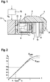
- Fig. 2 shows the Spindelmutterweg x as a function of time at the beginning of a Zuspannvorganges to build up braking or clamping force. Entered are two different curves x start and x true , which are determined on the basis of different parameters of the motor constants and the total motor resistance.
- Spindle nut travel x start represents the uncorrected travel of the spindle nut using non-current parameters of motor constant and total motor resistance.
- Spindle stroke x true is the corrected spindle nut travel determined using current parameters for motor constant and total resistance.
- the instant at which current estimates of the motor constants are obtained, which are determined from the supply voltage U S and the motor current i A when the motor is idling, is marked t param .
- the Spindelmutterweg is in the idle phase in a constant increase, which can be approximately represented as a straight line.
- a constant increase which can be approximately represented as a straight line.
- t 1 and t 2 which are true in the linear increase of x start and x and between which is the time t param , at which the estimation of the motor constant and the motor total resistance is present.
- Fig. 3 a flow chart for determining the Spindelmutterwegs is shown with high accuracy. This makes it possible to determine the travel of the spindle nut, in particular to reduce the free travel of the spindle nut, so that During a tightening process, the time span is reduced until the construction of a desired braking force without the risk of brake grinding.
- the angular velocity ⁇ depends on the motor constant K M and the total motor resistance R ges ; these parameters are either present as non-current start values K M, start and R ges, start before or, after the time t param , as current estimated values K M, est or R ges, est .
- the motor constant and the total motor resistance are either supplied from a block 22 as non-current values or a block 23 as current estimates and used in the calculation of the angular velocity in block 21, wherein in blocks 24 and 25, the angular velocity ⁇ start or the estimated angular velocity ⁇ est are supplied.
- the respective angular velocity value is fed to a following block 26 in which the spindle nut velocity V Sp is calculated.
- the starting speed v Sp, start of the spindle nut and the estimated speed v Sp est of the spindle nut are supplied according to the blocks 27 and 28 to a further step 29, which marks the beginning of the error compensation.
- x delta t 1 K M . begin ⁇ S sp 2 ⁇ ⁇ ⁇ i sep ⁇ ⁇ U S t - R ges .
- the corrected spindle pitch x true is passed on in step 35 and becomes the following in step 36 x begin .
- sidewalk x begin t 2 - x begin t 1 t 2 - t 1 x true .
- sidewalk x true t 2 - x true t 1 t 2 - t 1 .
- the time parameter t param is supplied to the step 39 from the step 23.
- the absolute position of the spindle nut based on an initial value, fixed, and it can be adjusted with a small clearance in front of the brake piston, so that when an operation of the brake motor only a minimal time elapses until the build-up of braking force.
Landscapes
- Engineering & Computer Science (AREA)
- General Engineering & Computer Science (AREA)
- Mechanical Engineering (AREA)
- Transportation (AREA)
- Braking Systems And Boosters (AREA)
- Braking Arrangements (AREA)
- Transmission Devices (AREA)
Claims (11)
- Procédé de mesure d'une course de réglage dans un dispositif de frein électromécanique (1) doté d'un moteur frein (3) électrique dans un véhicule, dont l'arbre moteur entraîne une broche (4), sur laquelle repose un écrou de broche (5) qui est ajusté par le biais du mouvement de rotation de la broche (4) dans la direction d'un piston de frein (6), dans lequel le trajet de l'écrou de broche (xstart) est également mesuré en prenant en compte une valeur de sortie de constante de moteur (KM,start) et une valeur de sortie de résistance moteur totale (Rges,start) puis, après que l'estimation a été effectuée, une correction du trajet de l'écrou de broche (xstart) est effectuée en prenant en compte une valeur estimée de constante de moteur (KM,est) et une valeur estimée de constante de résistance moteur totale (Rges,start).
- Procédé selon la revendication 1, caractérisé en ce que le trajet de l'écrou de broche (xstart) est calculé en prenant en compte la tension d'alimentation (Us) et l'intensité moteur (iA), avec la valeur de sortie de constante de moteur (KM,start) et la valeur de sortie de résistance moteur totale (Rges,start), selon

- Procédé selon la revendication 2, caractérisé en ce qu'un trajet de correction (xdelta) est mesuré à partir de


- Procédé selon la revendication 3, caractérisé en ce que, comme autre erreur, la déviation (xdef) entre l'augmentation (xstart,steig) du trajet d'écrou de broche avec une valeur estimée non-actuelle de constante de moteur (KM,start) ou une valeur estimée non-actuelle de constante de résistance moteur totale (Rges,start) et l'augmentation (xwahr,steig) du trajet d'écrou de broche corrigé (xwahr) avec une valeur estimée actuelle de constante de moteur (KM,est) ou une valeur estimée actuelle de constante de résistance moteur totale (Rges,est) :


- Procédé selon la revendication 4, caractérisé en ce que le trajet total corrigé (xges) de l'écrou de broche (5) est mesuré en prenant en compte la déviation (xdef) :

- Procédé selon l'une des revendications 1 à 5, caractérisé en ce que des valeurs estimées provenant d'une précédente opération de serrage ou de desserrage du dispositif de frein électromécanique (1) sont utilisées comme valeur de sortie de constante de moteur (KM,start) et comme valeur de sortie de résistance moteur totale (Rges,start).
- Procédé selon l'une des revendications 1 à 6, caractérisé en ce que le procédé est effectué lors d'une opération de serrage du dispositif de frein électromécanique (1).
- Procédé selon l'une des revendications 1 à 7, caractérisé en ce que le procédé est effectué lors d'une opération de desserrage du dispositif de frein électromécanique (1).
- Procédé selon la revendication 8, caractérisé en ce que le trajet de l'écrou de broche (xstart) est mesuré en premier avec le début de la phase de ralenti du moteur frein (3).
- Appareil de commande ou de contrôle (12) destiné à effectuer un procédé selon l'une des revendications 1 à 9.
- Dispositif de frein électromécanique doté d'un moteur frein électrique (3) dans un véhicule, doté d'un appareil de commande ou de contrôle (12) selon la revendication 10 destiné à commander les composants réglables du dispositif de frein (1).
Applications Claiming Priority (2)
| Application Number | Priority Date | Filing Date | Title |
|---|---|---|---|
| DE102015211468.6A DE102015211468A1 (de) | 2015-06-22 | 2015-06-22 | Verfahren zur Ermittlung des Stellwegs in einer elektromechanischen Bremsvorrichtung |
| PCT/EP2016/059238 WO2016206832A1 (fr) | 2015-06-22 | 2016-04-26 | Procédé de détermination de la course de réglage dans un dispositif de freinage électromécanique |
Publications (2)
| Publication Number | Publication Date |
|---|---|
| EP3310630A1 EP3310630A1 (fr) | 2018-04-25 |
| EP3310630B1 true EP3310630B1 (fr) | 2019-06-26 |
Family
ID=55969100
Family Applications (1)
| Application Number | Title | Priority Date | Filing Date |
|---|---|---|---|
| EP16722550.7A Active EP3310630B1 (fr) | 2015-06-22 | 2016-04-26 | Procédé de détermination de la course de réglage dans un dispositif de freinage électromécanique |
Country Status (7)
| Country | Link |
|---|---|
| US (1) | US10604132B2 (fr) |
| EP (1) | EP3310630B1 (fr) |
| JP (1) | JP6559261B2 (fr) |
| KR (1) | KR102537020B1 (fr) |
| CN (1) | CN107743461B (fr) |
| DE (1) | DE102015211468A1 (fr) |
| WO (1) | WO2016206832A1 (fr) |
Families Citing this family (5)
| Publication number | Priority date | Publication date | Assignee | Title |
|---|---|---|---|---|
| JP2018070083A (ja) * | 2016-11-04 | 2018-05-10 | Ntn株式会社 | 電動ブレーキ装置 |
| DE102017211176A1 (de) | 2017-06-30 | 2019-01-03 | Robert Bosch Gmbh | Verfahren zum Betreiben einer Bremsanlage eines Kraftfahrzeugs, sowie Steuer- und Regeleinrichtung |
| EP3698065B1 (fr) * | 2017-10-16 | 2021-05-26 | ZF CV Systems Europe BV | Dispositif de freinage, en particulier frein à disque de véhicule utilitaire |
| WO2024120695A1 (fr) * | 2022-12-08 | 2024-06-13 | Thyssenkrupp Presta Ag | Procédé de fonctionnement d'un dispositif de freinage électromécanique et dispositif de freinage électromécanique pour un véhicule à moteur |
| BE1031118B1 (de) * | 2022-12-08 | 2024-07-08 | Thyssenkrupp Presta Ag | Elektromechanische Bremsvorrichtung für ein Kraftfahrzeug und Verfahren zum Betrieb einer elektromechanischen Bremsvorrichtung |
Family Cites Families (16)
| Publication number | Priority date | Publication date | Assignee | Title |
|---|---|---|---|---|
| DE102006052810B4 (de) * | 2006-11-09 | 2021-09-02 | Robert Bosch Gmbh | Verfahren zur Abschätzung einer Kraftentfaltung eines an eine Versorgungsspannung anschließbaren Aktuators |
| DE102009028505A1 (de) * | 2009-08-13 | 2011-02-17 | Robert Bosch Gmbh | Verfahren zum Einstellen der Klemmkraft einer hydraulisch unterstützten elektromotorischen Feststellbremse |
| DE102010002825A1 (de) * | 2010-03-12 | 2011-09-15 | Robert Bosch Gmbh | Verfahren zum Einstellen der von einer Feststellbremse ausgeübten Klemmkraft |
| DE102011004704A1 (de) | 2011-02-25 | 2012-08-30 | Robert Bosch Gmbh | Verfahren zum Einstellen einer Feststellbremse in einem Fahrzeug |
| DE102011078900B4 (de) | 2011-07-08 | 2024-06-20 | Robert Bosch Gmbh | Verfahren zum Einstellen einer Feststellbremse in einem Fahrzeug |
| DE102012202959A1 (de) | 2012-02-27 | 2013-08-29 | Robert Bosch Gmbh | Verfahren zum Bereitstellen der von einer Feststellbremse erzeugten Klemmkraft |
| DE102012205576A1 (de) * | 2012-04-04 | 2013-10-10 | Robert Bosch Gmbh | Verfahren zum Bereitstellen der von einer Feststellbremse erzeugten Klemmkraft |
| DE102012206223A1 (de) | 2012-04-16 | 2013-10-17 | Robert Bosch Gmbh | Verfahren zum Einstellen einer Feststellbremse in einem Fahrzeug |
| DE102012206226A1 (de) * | 2012-04-16 | 2013-10-17 | Robert Bosch Gmbh | Verfahren zum Einstellen einer Feststellbremse in einem Fahrzeug |
| KR101331783B1 (ko) | 2012-09-10 | 2013-11-21 | 주식회사 만도 | 주차기능을 갖는 전자식 캘리퍼 브레이크 |
| DE102012223178A1 (de) | 2012-12-14 | 2014-06-18 | Robert Bosch Gmbh | Verfahren zum Betätigen einer Feststellbremse mit einem elektromotorisch angetriebenen Feststellbrems-Mechanismus |
| DE102012025423A1 (de) * | 2012-12-21 | 2014-06-26 | Lucas Automotive Gmbh | Elektrohydraulische Fahrzeug-Bremsanlage und Verfahren zum Betreiben derselben |
| DE102013201403A1 (de) | 2013-01-29 | 2014-07-31 | Robert Bosch Gmbh | Automatische Parkbremse mit optimiertem Nachspannverfahren |
| DE102013022058B4 (de) * | 2013-12-23 | 2024-02-29 | Zf Active Safety Gmbh | Elektromechanisch und hydraulisch betätigbare Kraftfahrzeugbremse mit wahlweiser Selbsthemmung |
| DE102014200602A1 (de) * | 2014-01-15 | 2015-07-16 | Ford Global Technologies, Llc | Verfahren zum Betreiben einer Bremsvorrichtung mit Betriebs- und Feststellbremsfunktion |
| DE102014203350A1 (de) * | 2014-02-25 | 2015-08-27 | Robert Bosch Gmbh | Verfahren zum Einstellen einer Feststellbremse in einem Fahrzeug |
-
2015
- 2015-06-22 DE DE102015211468.6A patent/DE102015211468A1/de not_active Withdrawn
-
2016
- 2016-04-26 KR KR1020177036919A patent/KR102537020B1/ko active IP Right Grant
- 2016-04-26 JP JP2017563252A patent/JP6559261B2/ja active Active
- 2016-04-26 WO PCT/EP2016/059238 patent/WO2016206832A1/fr active Application Filing
- 2016-04-26 EP EP16722550.7A patent/EP3310630B1/fr active Active
- 2016-04-26 CN CN201680036540.2A patent/CN107743461B/zh active Active
- 2016-04-26 US US15/738,604 patent/US10604132B2/en active Active
Non-Patent Citations (1)
| Title |
|---|
| None * |
Also Published As
| Publication number | Publication date |
|---|---|
| US20180194338A1 (en) | 2018-07-12 |
| US10604132B2 (en) | 2020-03-31 |
| JP2018516206A (ja) | 2018-06-21 |
| KR20180020171A (ko) | 2018-02-27 |
| DE102015211468A1 (de) | 2016-12-22 |
| CN107743461B (zh) | 2020-02-21 |
| WO2016206832A1 (fr) | 2016-12-29 |
| EP3310630A1 (fr) | 2018-04-25 |
| KR102537020B1 (ko) | 2023-05-30 |
| CN107743461A (zh) | 2018-02-27 |
| JP6559261B2 (ja) | 2019-08-14 |
Similar Documents
| Publication | Publication Date | Title |
|---|---|---|
| EP3310630B1 (fr) | Procédé de détermination de la course de réglage dans un dispositif de freinage électromécanique | |
| EP2707263B1 (fr) | Technique de détermination d'une force d'actionnement appliquée sur un frein de véhicule à commande hydraulique et mécanique | |
| DE102011078900B4 (de) | Verfahren zum Einstellen einer Feststellbremse in einem Fahrzeug | |
| EP2651723B1 (fr) | Procédé de réglage de la force de serrage exercée par un frein de stationnement | |
| DE102011006419A1 (de) | Elektrische Bremsvorrichtung | |
| WO2013149743A1 (fr) | Procédé de mise à disposition d'une force de serrage produite par un frein de stationnement | |
| EP2838767B1 (fr) | Procédé destiné au réglage d'un frein de stationnement dans un véhicule | |
| EP2651733B1 (fr) | Procédé permettant d'ajuster la force de serrage exercée par un frein de stationnement | |
| DE102014203350A1 (de) | Verfahren zum Einstellen einer Feststellbremse in einem Fahrzeug | |
| DE102016219835A1 (de) | Verfahren und Vorrichtung zur Steuerung eines motorangetriebenen Servolenksystems | |
| DE102015211461A1 (de) | Verfahren zum Überprüfen der Bremskraft in einem Fahrzeug | |
| DE102015210431A1 (de) | Verfahren zum Ansteuern einer Feststellbremse in einem Fahrzeug | |
| EP2651721B1 (fr) | Procédé de réglage de la force de serrage exercée par un frein de stationnement | |
| EP2719597B1 (fr) | Procédé de commande d'un système de freinage | |
| DE102016209042A1 (de) | Verfahren zum Überwachen der Bremskraft in einem Fahrzeug | |
| EP2688778A1 (fr) | Procédé de réglage d'un frein de stationnement dans un véhicule | |
| EP3645357B1 (fr) | Procédé et dispositif pour faire fonctionner un frein de stationnement automatique | |
| DE102011004741B4 (de) | Verfahren zum Einstellen einer Feststellbremse in einem Fahrzeug | |
| DE102016214195A1 (de) | Verfahren zur Funktionsprüfung einer elektromechanischen Bremsvorrichtung | |
| EP3331737B1 (fr) | Procédé pour vérifier la force de frein de stationnement dans un véhicule | |
| DE102015219303A1 (de) | Fahrzeug, elektromechanischer Bremskraftverstärker, Zustandsregler und Verfahren zur Bestimmung einer elektromechanischen Soll-Bremskraft | |
| EP3247597B1 (fr) | Méthode de actuation d'un frein de stationnement et frein de stationnement | |
| DE102010039309A1 (de) | Verfahren zur Ermittlung des Wirkungsgrades einer elektrisch betätigbaren Feststellbremse in einem Fahrzeug | |
| DE102015207333B4 (de) | Verfahren und Vorrichtung zum Generieren eines Lenkwinkels | |
| DE102010052924A1 (de) | Elektromechanischer Bremskraftverstärker |
Legal Events
| Date | Code | Title | Description |
|---|---|---|---|
| STAA | Information on the status of an ep patent application or granted ep patent |
Free format text: STATUS: THE INTERNATIONAL PUBLICATION HAS BEEN MADE |
|
| PUAI | Public reference made under article 153(3) epc to a published international application that has entered the european phase |
Free format text: ORIGINAL CODE: 0009012 |
|
| STAA | Information on the status of an ep patent application or granted ep patent |
Free format text: STATUS: REQUEST FOR EXAMINATION WAS MADE |
|
| 17P | Request for examination filed |
Effective date: 20180122 |
|
| AK | Designated contracting states |
Kind code of ref document: A1 Designated state(s): AL AT BE BG CH CY CZ DE DK EE ES FI FR GB GR HR HU IE IS IT LI LT LU LV MC MK MT NL NO PL PT RO RS SE SI SK SM TR |
|
| AX | Request for extension of the european patent |
Extension state: BA ME |
|
| RIN1 | Information on inventor provided before grant (corrected) |
Inventor name: PUTZER, TOBIAS Inventor name: ENGLERT, ANDREAS Inventor name: BAEHRLE-MILLER, FRANK |
|
| DAV | Request for validation of the european patent (deleted) | ||
| DAX | Request for extension of the european patent (deleted) | ||
| GRAP | Despatch of communication of intention to grant a patent |
Free format text: ORIGINAL CODE: EPIDOSNIGR1 |
|
| STAA | Information on the status of an ep patent application or granted ep patent |
Free format text: STATUS: GRANT OF PATENT IS INTENDED |
|
| INTG | Intention to grant announced |
Effective date: 20181217 |
|
| GRAJ | Information related to disapproval of communication of intention to grant by the applicant or resumption of examination proceedings by the epo deleted |
Free format text: ORIGINAL CODE: EPIDOSDIGR1 |
|
| STAA | Information on the status of an ep patent application or granted ep patent |
Free format text: STATUS: REQUEST FOR EXAMINATION WAS MADE |
|
| GRAP | Despatch of communication of intention to grant a patent |
Free format text: ORIGINAL CODE: EPIDOSNIGR1 |
|
| STAA | Information on the status of an ep patent application or granted ep patent |
Free format text: STATUS: GRANT OF PATENT IS INTENDED |
|
| INTC | Intention to grant announced (deleted) | ||
| INTG | Intention to grant announced |
Effective date: 20190402 |
|
| GRAS | Grant fee paid |
Free format text: ORIGINAL CODE: EPIDOSNIGR3 |
|
| GRAA | (expected) grant |
Free format text: ORIGINAL CODE: 0009210 |
|
| STAA | Information on the status of an ep patent application or granted ep patent |
Free format text: STATUS: THE PATENT HAS BEEN GRANTED |
|
| AK | Designated contracting states |
Kind code of ref document: B1 Designated state(s): AL AT BE BG CH CY CZ DE DK EE ES FI FR GB GR HR HU IE IS IT LI LT LU LV MC MK MT NL NO PL PT RO RS SE SI SK SM TR |
|
| REG | Reference to a national code |
Ref country code: GB Ref legal event code: FG4D Free format text: NOT ENGLISH |
|
| REG | Reference to a national code |
Ref country code: CH Ref legal event code: EP |
|
| REG | Reference to a national code |
Ref country code: AT Ref legal event code: REF Ref document number: 1147921 Country of ref document: AT Kind code of ref document: T Effective date: 20190715 |
|
| REG | Reference to a national code |
Ref country code: IE Ref legal event code: FG4D Free format text: LANGUAGE OF EP DOCUMENT: GERMAN |
|
| REG | Reference to a national code |
Ref country code: DE Ref legal event code: R096 Ref document number: 502016005264 Country of ref document: DE |
|
| REG | Reference to a national code |
Ref country code: NL Ref legal event code: MP Effective date: 20190626 |
|
| PG25 | Lapsed in a contracting state [announced via postgrant information from national office to epo] |
Ref country code: HR Free format text: LAPSE BECAUSE OF FAILURE TO SUBMIT A TRANSLATION OF THE DESCRIPTION OR TO PAY THE FEE WITHIN THE PRESCRIBED TIME-LIMIT Effective date: 20190626 Ref country code: NO Free format text: LAPSE BECAUSE OF FAILURE TO SUBMIT A TRANSLATION OF THE DESCRIPTION OR TO PAY THE FEE WITHIN THE PRESCRIBED TIME-LIMIT Effective date: 20190926 Ref country code: LT Free format text: LAPSE BECAUSE OF FAILURE TO SUBMIT A TRANSLATION OF THE DESCRIPTION OR TO PAY THE FEE WITHIN THE PRESCRIBED TIME-LIMIT Effective date: 20190626 Ref country code: SE Free format text: LAPSE BECAUSE OF FAILURE TO SUBMIT A TRANSLATION OF THE DESCRIPTION OR TO PAY THE FEE WITHIN THE PRESCRIBED TIME-LIMIT Effective date: 20190626 Ref country code: AL Free format text: LAPSE BECAUSE OF FAILURE TO SUBMIT A TRANSLATION OF THE DESCRIPTION OR TO PAY THE FEE WITHIN THE PRESCRIBED TIME-LIMIT Effective date: 20190626 Ref country code: FI Free format text: LAPSE BECAUSE OF FAILURE TO SUBMIT A TRANSLATION OF THE DESCRIPTION OR TO PAY THE FEE WITHIN THE PRESCRIBED TIME-LIMIT Effective date: 20190626 |
|
| REG | Reference to a national code |
Ref country code: LT Ref legal event code: MG4D |
|
| PG25 | Lapsed in a contracting state [announced via postgrant information from national office to epo] |
Ref country code: BG Free format text: LAPSE BECAUSE OF FAILURE TO SUBMIT A TRANSLATION OF THE DESCRIPTION OR TO PAY THE FEE WITHIN THE PRESCRIBED TIME-LIMIT Effective date: 20190926 Ref country code: GR Free format text: LAPSE BECAUSE OF FAILURE TO SUBMIT A TRANSLATION OF THE DESCRIPTION OR TO PAY THE FEE WITHIN THE PRESCRIBED TIME-LIMIT Effective date: 20190927 Ref country code: LV Free format text: LAPSE BECAUSE OF FAILURE TO SUBMIT A TRANSLATION OF THE DESCRIPTION OR TO PAY THE FEE WITHIN THE PRESCRIBED TIME-LIMIT Effective date: 20190626 Ref country code: RS Free format text: LAPSE BECAUSE OF FAILURE TO SUBMIT A TRANSLATION OF THE DESCRIPTION OR TO PAY THE FEE WITHIN THE PRESCRIBED TIME-LIMIT Effective date: 20190626 |
|
| PG25 | Lapsed in a contracting state [announced via postgrant information from national office to epo] |
Ref country code: NL Free format text: LAPSE BECAUSE OF FAILURE TO SUBMIT A TRANSLATION OF THE DESCRIPTION OR TO PAY THE FEE WITHIN THE PRESCRIBED TIME-LIMIT Effective date: 20190626 Ref country code: SK Free format text: LAPSE BECAUSE OF FAILURE TO SUBMIT A TRANSLATION OF THE DESCRIPTION OR TO PAY THE FEE WITHIN THE PRESCRIBED TIME-LIMIT Effective date: 20190626 Ref country code: PT Free format text: LAPSE BECAUSE OF FAILURE TO SUBMIT A TRANSLATION OF THE DESCRIPTION OR TO PAY THE FEE WITHIN THE PRESCRIBED TIME-LIMIT Effective date: 20191028 Ref country code: CZ Free format text: LAPSE BECAUSE OF FAILURE TO SUBMIT A TRANSLATION OF THE DESCRIPTION OR TO PAY THE FEE WITHIN THE PRESCRIBED TIME-LIMIT Effective date: 20190626 Ref country code: RO Free format text: LAPSE BECAUSE OF FAILURE TO SUBMIT A TRANSLATION OF THE DESCRIPTION OR TO PAY THE FEE WITHIN THE PRESCRIBED TIME-LIMIT Effective date: 20190626 Ref country code: EE Free format text: LAPSE BECAUSE OF FAILURE TO SUBMIT A TRANSLATION OF THE DESCRIPTION OR TO PAY THE FEE WITHIN THE PRESCRIBED TIME-LIMIT Effective date: 20190626 |
|
| PG25 | Lapsed in a contracting state [announced via postgrant information from national office to epo] |
Ref country code: SM Free format text: LAPSE BECAUSE OF FAILURE TO SUBMIT A TRANSLATION OF THE DESCRIPTION OR TO PAY THE FEE WITHIN THE PRESCRIBED TIME-LIMIT Effective date: 20190626 Ref country code: IS Free format text: LAPSE BECAUSE OF FAILURE TO SUBMIT A TRANSLATION OF THE DESCRIPTION OR TO PAY THE FEE WITHIN THE PRESCRIBED TIME-LIMIT Effective date: 20191026 Ref country code: ES Free format text: LAPSE BECAUSE OF FAILURE TO SUBMIT A TRANSLATION OF THE DESCRIPTION OR TO PAY THE FEE WITHIN THE PRESCRIBED TIME-LIMIT Effective date: 20190626 Ref country code: IT Free format text: LAPSE BECAUSE OF FAILURE TO SUBMIT A TRANSLATION OF THE DESCRIPTION OR TO PAY THE FEE WITHIN THE PRESCRIBED TIME-LIMIT Effective date: 20190626 |
|
| PG25 | Lapsed in a contracting state [announced via postgrant information from national office to epo] |
Ref country code: TR Free format text: LAPSE BECAUSE OF FAILURE TO SUBMIT A TRANSLATION OF THE DESCRIPTION OR TO PAY THE FEE WITHIN THE PRESCRIBED TIME-LIMIT Effective date: 20190626 |
|
| RAP2 | Party data changed (patent owner data changed or rights of a patent transferred) |
Owner name: ROBERT BOSCH GMBH |
|
| PG25 | Lapsed in a contracting state [announced via postgrant information from national office to epo] |
Ref country code: DK Free format text: LAPSE BECAUSE OF FAILURE TO SUBMIT A TRANSLATION OF THE DESCRIPTION OR TO PAY THE FEE WITHIN THE PRESCRIBED TIME-LIMIT Effective date: 20190626 Ref country code: PL Free format text: LAPSE BECAUSE OF FAILURE TO SUBMIT A TRANSLATION OF THE DESCRIPTION OR TO PAY THE FEE WITHIN THE PRESCRIBED TIME-LIMIT Effective date: 20190626 |
|
| PG25 | Lapsed in a contracting state [announced via postgrant information from national office to epo] |
Ref country code: IS Free format text: LAPSE BECAUSE OF FAILURE TO SUBMIT A TRANSLATION OF THE DESCRIPTION OR TO PAY THE FEE WITHIN THE PRESCRIBED TIME-LIMIT Effective date: 20200224 |
|
| REG | Reference to a national code |
Ref country code: DE Ref legal event code: R097 Ref document number: 502016005264 Country of ref document: DE |
|
| PLBE | No opposition filed within time limit |
Free format text: ORIGINAL CODE: 0009261 |
|
| STAA | Information on the status of an ep patent application or granted ep patent |
Free format text: STATUS: NO OPPOSITION FILED WITHIN TIME LIMIT |
|
| PG2D | Information on lapse in contracting state deleted |
Ref country code: IS |
|
| 26N | No opposition filed |
Effective date: 20200603 |
|
| PG25 | Lapsed in a contracting state [announced via postgrant information from national office to epo] |
Ref country code: SI Free format text: LAPSE BECAUSE OF FAILURE TO SUBMIT A TRANSLATION OF THE DESCRIPTION OR TO PAY THE FEE WITHIN THE PRESCRIBED TIME-LIMIT Effective date: 20190626 |
|
| PG25 | Lapsed in a contracting state [announced via postgrant information from national office to epo] |
Ref country code: MC Free format text: LAPSE BECAUSE OF FAILURE TO SUBMIT A TRANSLATION OF THE DESCRIPTION OR TO PAY THE FEE WITHIN THE PRESCRIBED TIME-LIMIT Effective date: 20190626 |
|
| REG | Reference to a national code |
Ref country code: CH Ref legal event code: PL |
|
| PG25 | Lapsed in a contracting state [announced via postgrant information from national office to epo] |
Ref country code: LI Free format text: LAPSE BECAUSE OF NON-PAYMENT OF DUE FEES Effective date: 20200430 Ref country code: CH Free format text: LAPSE BECAUSE OF NON-PAYMENT OF DUE FEES Effective date: 20200430 Ref country code: LU Free format text: LAPSE BECAUSE OF NON-PAYMENT OF DUE FEES Effective date: 20200426 |
|
| REG | Reference to a national code |
Ref country code: BE Ref legal event code: MM Effective date: 20200430 |
|
| PG25 | Lapsed in a contracting state [announced via postgrant information from national office to epo] |
Ref country code: BE Free format text: LAPSE BECAUSE OF NON-PAYMENT OF DUE FEES Effective date: 20200430 |
|
| PG25 | Lapsed in a contracting state [announced via postgrant information from national office to epo] |
Ref country code: IE Free format text: LAPSE BECAUSE OF NON-PAYMENT OF DUE FEES Effective date: 20200426 |
|
| PG25 | Lapsed in a contracting state [announced via postgrant information from national office to epo] |
Ref country code: MT Free format text: LAPSE BECAUSE OF FAILURE TO SUBMIT A TRANSLATION OF THE DESCRIPTION OR TO PAY THE FEE WITHIN THE PRESCRIBED TIME-LIMIT Effective date: 20190626 Ref country code: CY Free format text: LAPSE BECAUSE OF FAILURE TO SUBMIT A TRANSLATION OF THE DESCRIPTION OR TO PAY THE FEE WITHIN THE PRESCRIBED TIME-LIMIT Effective date: 20190626 |
|
| REG | Reference to a national code |
Ref country code: AT Ref legal event code: MM01 Ref document number: 1147921 Country of ref document: AT Kind code of ref document: T Effective date: 20210426 |
|
| PG25 | Lapsed in a contracting state [announced via postgrant information from national office to epo] |
Ref country code: MK Free format text: LAPSE BECAUSE OF FAILURE TO SUBMIT A TRANSLATION OF THE DESCRIPTION OR TO PAY THE FEE WITHIN THE PRESCRIBED TIME-LIMIT Effective date: 20190626 |
|
| PG25 | Lapsed in a contracting state [announced via postgrant information from national office to epo] |
Ref country code: AT Free format text: LAPSE BECAUSE OF NON-PAYMENT OF DUE FEES Effective date: 20210426 |
|
| PGFP | Annual fee paid to national office [announced via postgrant information from national office to epo] |
Ref country code: FR Payment date: 20230417 Year of fee payment: 8 |
|
| PGFP | Annual fee paid to national office [announced via postgrant information from national office to epo] |
Ref country code: GB Payment date: 20230420 Year of fee payment: 8 |
|
| PGFP | Annual fee paid to national office [announced via postgrant information from national office to epo] |
Ref country code: DE Payment date: 20240619 Year of fee payment: 9 |