EP3310286B1 - Vorrichtung zur steuerung eines systems mit einer bildgebungsmodalität - Google Patents
Vorrichtung zur steuerung eines systems mit einer bildgebungsmodalität Download PDFInfo
- Publication number
- EP3310286B1 EP3310286B1 EP16751553.5A EP16751553A EP3310286B1 EP 3310286 B1 EP3310286 B1 EP 3310286B1 EP 16751553 A EP16751553 A EP 16751553A EP 3310286 B1 EP3310286 B1 EP 3310286B1
- Authority
- EP
- European Patent Office
- Prior art keywords
- instrument
- predefined
- imaging modality
- action
- view
- Prior art date
- Legal status (The legal status is an assumption and is not a legal conclusion. Google has not performed a legal analysis and makes no representation as to the accuracy of the status listed.)
- Active
Links
Images



Classifications
-
- A—HUMAN NECESSITIES
- A61—MEDICAL OR VETERINARY SCIENCE; HYGIENE
- A61B—DIAGNOSIS; SURGERY; IDENTIFICATION
- A61B34/00—Computer-aided surgery; Manipulators or robots specially adapted for use in surgery
- A61B34/30—Surgical robots
-
- A—HUMAN NECESSITIES
- A61—MEDICAL OR VETERINARY SCIENCE; HYGIENE
- A61B—DIAGNOSIS; SURGERY; IDENTIFICATION
- A61B1/00—Instruments for performing medical examinations of the interior of cavities or tubes of the body by visual or photographical inspection, e.g. endoscopes; Illuminating arrangements therefor
- A61B1/00002—Operational features of endoscopes
- A61B1/00043—Operational features of endoscopes provided with output arrangements
- A61B1/00045—Display arrangement
- A61B1/0005—Display arrangement combining images e.g. side-by-side, superimposed or tiled
-
- A—HUMAN NECESSITIES
- A61—MEDICAL OR VETERINARY SCIENCE; HYGIENE
- A61B—DIAGNOSIS; SURGERY; IDENTIFICATION
- A61B34/00—Computer-aided surgery; Manipulators or robots specially adapted for use in surgery
- A61B34/25—User interfaces for surgical systems
-
- A—HUMAN NECESSITIES
- A61—MEDICAL OR VETERINARY SCIENCE; HYGIENE
- A61B—DIAGNOSIS; SURGERY; IDENTIFICATION
- A61B6/00—Apparatus or devices for radiation diagnosis; Apparatus or devices for radiation diagnosis combined with radiation therapy equipment
- A61B6/46—Arrangements for interfacing with the operator or the patient
- A61B6/461—Displaying means of special interest
- A61B6/463—Displaying means of special interest characterised by displaying multiple images or images and diagnostic data on one display
Definitions
- the invention relates to a device for controlling a system comprising an imaging modality.
- the invention relates to a system comprising an imaging modality.
- WO 2015 / 091 226 A1 describes a system for providing a laparoscopic vision or view extended with X-ray vision.
- the System comprises a medical imaging device for acquiring an image of an anatomy and a laparoscope for generating a laparoscopic image of the interior of the anatomy.
- a processing device of the system is configured for receiving a signal representing a position and orientation of the laparoscope, and for combining the acquired image and the laparoscopic image into a combined view, which is then displayed.
- MIS minimal invasive surgery
- laparoscopic surgery has become popular because of its advantages over the conventional open surgery.
- surgeons treat a lesion inside the human body through small incisions, which cause less pain and allow faster recovery.
- an assistant is usually required to hold the endoscope/laparoscope in order to adapt its field of view to the anatomical and interventional situation, which may have certain drawbacks, e. g. trembling of the hand of the assistant cause image blurring resulting in eyestrain and concentration problems for the surgeons and/or costs of a second physician.
- a passive holder or robotic holder of the laparoscope could overcome some of this problem.
- the "solo" surgeon is required to release his hands from his surgical instruments in order to adjust the passive holder for each change of the laparoscopic viewing position. Depending on the surgical procedure, this may be difficult or even impossible.
- a robotic system may overcome this problem, when the surgeon is able to provide positioning commands to the robotic holder without using its hands.
- the communication between the robotic system and the surgeons is however a sensible part of a such as system since it needs to be intuitive, fast, reliable and very safe given the sensible environment such a robotic device is working in.
- Robotic holders that provide human-machine interfaces that are suitable for solo surgery are also commercially available or have been presented in literature. Often they require additional hardware to establish a reliable human machine interface to the robot, e.g. food pedal, voice control (e.g. Buess, G. F., A. Arezzo, M. O. Schurr, F. Ulmer, H. Fisher, L. Gumb, T. Testa, and C. Nobman. "A new remote-controlled endoscope positioning system for endoscopic solo surgery.” Surgical endoscopy 14, no. 4 (2000): 395-399 .), or tracking systems.
- voice control e.g. Buess, G. F., A. Arezzo, M. O. Schurr, F. Ulmer, H. Fisher, L. Gumb, T. Testa, and C. Nobman.
- the publication EP 2 744 419 A2 discloses a device for assisting laparoscopic surgery.
- the international publication WO 2015/110882 A1 discloses a robotic control of imaging devices with optical shape sensing.
- US publication US 2013/0216025 A1 discloses an adaptive imaging and frame rate optimizing based on real-time shaped sensing of medical instruments.
- the underlying technical problem of the invention is to facilitate an improved controlling of a system comprising an imaging modality.
- a method for controlling a system comprising an imaging modality is disclosed in this application, but not claimed. However, the description of the method and their embodiments allow a better understanding of the device and the system. Whenever the formulation "This disclosure relates" is mentioned, the disclosure shall facilitate the understanding without claiming the method.
- the method comprises:
- This disclosure relates in one aspect to a method comprising:
- This disclosure relates in one aspect to a method, wherein the predefined portion of the field of view is selected from a plurality of predefined portions of the field of view, wherein each portion of the plurality of predefined portions of the field of view is assigned to one of a plurality of different predefined actions.
- This disclosure relates in one aspect to a method, the method comprising:
- This disclosure relates in one aspect to a method, the method comprising:
- This disclosure relates in one aspect to a method, the method comprising:
- This disclosure relates in one aspect to a method, the method comprising:
- This disclosure relates in one aspect to a method, said part of the instrument comprising a plurality of components, wherein each state of the plurality of predefined first states is assigned to one of a plurality of different positions and/or orientations of the components relative to each other and/or wherein each movement of the plurality of predefined movements is assigned to one of a plurality of different movements of the components relative to each other.
- This disclosure relates in one aspect to a method, the instrument comprising a grasper and/or a scissor, the plurality of predefined first states comprising an open state of the grasper and/or the scissor and a closed state of the grasper and/or the scissor and/or the plurality of predefined movements comprising an opening movement of the grasper and/or the scissor and a closing movement of the grasper and/or the scissor.
- This disclosure relates in one aspect to a method, wherein the predefined action includes changing a condition that is related to an acquisition of the image.
- This disclosure relates in one aspect to a method, wherein the predefined action includes changing a condition that is selected from the group consisting of the field of view of the image, an angle of view of the image, a zoom of the image, a resolution of the image, a focus of the image, a position of an imaging data acquisition component of the imaging modality relative to said portion of said patient and/or relative to said part of said instrument, an orientation of the imaging data acquisition component of the imaging modality relative to said portion of said patient and/or relative to said part of said instrument and combinations thereof.
- This disclosure relates in one aspect to a method, said action unit comprising the imaging modality and/or a positioning device for positioning and/or orienting an imaging data acquisition component of the imaging modality relative to said portion of said patient and/or relative to said part of said instrument.
- This disclosure relates in one aspect to a method, the method comprising:
- This disclosure relates in one aspect to a method, said part of the instrument representing a pointer element of the graphical user interface.
- This disclosure relates in one aspect to a method, wherein the imaging modality is selected from the group consisting of an optical imaging modality, a laparoscopic imaging modality, an endoscopic imaging modality and an x-ray imaging modality and/or wherein the imaging data acquisition component is selected from the group consisting of a camera, a laparoscope, an endoscope and an x-ray detector.
- This disclosure relates in one aspect to a method, the method comprising
- the instrument is a surgical instrument.
- said part of the instrument is a tip and/or head of the instrument.
- This disclosure relates in one aspect to a method, the method comprising determining whether said part of the instrument executes a given movement selected from a plurality of predefined movements throughout the series of the images.
- This disclosure relates in one aspect to a method, the method comprising generating a control command for performing a predefined action of an action unit of the system depending on whether said part of the instrument executes the given movement selected from the plurality of predefined movements throughout the series of the images.
- the invention relates in one aspect to a device comprising:
- the invention relates in one aspect to a device for executing the method according to any one of the aspects of the invention described herein.
- the invention relates in one aspect to a system comprising
- the invention relates in one aspect to a system, said action unit comprising the imaging modality and/or a positioning device for positioning and/or orienting an imaging data acquisition component of the imaging modality relative to said portion of said patient and/or relative to said part of said instrument.
- the imaging modality and/or the positioning device perform the predefined action.
- the invention relates in one aspect to a system for executing the method according to any one of the aspects of the invention described herein.
- This disclosure relates in one aspect to a computer program product comprising a computer program, the computer program being loadable directly into a memory unit of a control unit of the system according to any one of the aspects of the invention described herein, including program code sections to make the system execute the method according to any one of the aspects of the invention described herein when the computer program is executed in said control unit.
- This disclosure relates in one aspect to a machine-readable medium, on which program code sections of a computer program are saved, said program code sections being loadable directly into and/or executable in a processing unit of a control unit of the system according to any one of the aspects of the invention described herein to make the system execute the method according to any one of the aspects of the invention described herein when the program code sections are executed in said processing unit.
- the positioning device comprises a robot and/or a robotic laparoscopic holder.
- the positioning device is a robot and/or a robotic laparoscopic holder.
- the inventors propose a way of providing positioning commands to a robotic laparoscopic holder using a specific propriety of an instrument, wherein at least a part of the instrument is covered by the field of view of the laparoscopic image. Therefore a surgical instrument already introduced in the human body cavity can be used to provide an intuitive human-machine interface to the physician. No additional hardware is necessary
- control commands can be generated for performing a predefined action of an action unit of the system. For example Opening/Closing of surgical graspers and/or scissors are among two of such gestures.
- the inventors propose to use a surgical instrument as a pointer element of a graphical user interface with the following steps:
- the instrument or industrial tool can only be used as a pointer element, when the tool is in a specific state, e.g. the grasper of a surgical tool is open.
- the graphical user interface is a control interface of the action unit and/or a virtual control interface of the action unit.
- At least one step of the method or the entire process can be activated or deactivated by the surgeon using the operating element.
- the operating element can be for example a foot switch and/or a safety switch.
- the invention enables the utilization of a surgical instrument as a pointer element in conjunction with a graphical user interface superimposed on a laparoscopic image, e. g. of the inside of the human body cavity, to control the movement of a robotic laparoscopic holder.
- the invention enables using existing mechanically modifiable, e. g. from outside the human body cavity, states, e.g. grasper open or closed states, of a surgical instruments to trigger, alter, active or deactivate a control element of the graphical user interface and/or a predefined action of an action unit.
- states e.g. grasper open or closed states
- Fig. 1 shows a diagram illustrating a method with the following steps:
- Fig. 2 shows a diagram illustrating a method with the steps RI, DP and GC and the following steps:
- Fig. 3 shows a device 35 comprising:
- Fig. 4 shows a device 35 comprising the receiving unit 41, first determining unit 42, the generating unit 43, the device 35 further comprising:
- Fig. 5 shows a flow diagram illustrating a method according to one aspect of this disclosure.
- Step 60 comprises inserting the laparoscope into the patient.
- Step 61 comprises inserting the instrument into the patient.
- Step 62 comprises determining DO whether the operating element 37 of the system 1 is in a given state selected from a plurality of predefined second states. If the operating element 37 is not in the given state selected from the plurality of predefined second states, the corresponding path labeled with "N" is followed returning to step 62. If the operating element 37 is in the given state selected from the plurality of predefined second states, the path labeled with "Y" is followed.
- Step 63 comprises determining DP whether said part 21 of the instrument 20 is located within a predefined portion 51 of the field of view. If said part 21 of the instrument 20 is not located within the predefined portion 51 of the field of view, the corresponding path labeled with "N" is followed returning to step 62. If said part 21 of the instrument 20 is located within the predefined portion 51 of the field of view, the path leading to step 64 is followed. Step 64 comprises determining DP whether said part 21 of the instrument 20 is in a given state selected from a plurality of predefined first states.
- Step 66 comprises locating and/or determining a position and/or a displacement of said part 21 of the instrument 20.
- Step 67 comprises tracking of said part 21 of the instrument 20. In step 67 the positioning device follows the position and/or the displacement of said part 21 of the instrument 20.
- Step 71 comprises determining DP whether said part 21 of the instrument 20 is located within a predefined portion 52, 53 of the field of view. If said part 21 of the instrument 20 is located within portion 52 of the field of view, the path 73 is followed. If said part 21 of the instrument 20 is located within portion 53 of the field of view, the path 72 is followed. Else path 74 is followed.
- Step 75 comprises generating a control command for performing a first predefined action of the action unit 3, 34, 5 of the system 1, wherein the portion 51 is assigned to the first predefined action.
- Step 75 comprises generating a control command for performing a first predefined action of the action unit 3, 34, 5 of the system 1, wherein the portion 52 is assigned to the first predefined action.
- Step 76 comprises generating a control command for performing a second predefined action of the action unit 3, 34, 5 of the system 1, wherein the portion 53 is assigned to the second predefined action.
- step 62 After executing at least one of the steps 67, 75, and 76 a path returning to step 62 is followed.
- the first predefined action comprises zooming in and/or moving the imaging data acquisition component towards the instrument.
- the second predefined action comprises zooming out and/or moving the imaging data acquisition component away from said part 21 of said instrument 20.
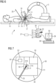
- Fig. 6 shows a system according to one aspect of the invention, the system 1 comprising
- the system further comprises the control unit 30, the display device 39 and an input device 38 for control inputs.
- the control unit 30 comprises a processing unit 33.
- the device 35 and/or one or many or all components of the device 35 are implemented in a processor system of the processing unit 33.
- the processor system comprises one or several microprocessors.
- the imaging modality 3, 34 comprises an imaging data acquisition component 3.
- the imaging modality 3, 34 comprises an imaging modality control unit 34 for controlling the imaging modality 3, 34 and/or the imaging data acquisition component 3.
- the arrows 15, 17 and 19 indicate degrees of freedom of a position of the imaging data acquisition component 3 and/or an orientation of the imaging data acquisition component 3.
- the degree of freedom indicated by the arrow 15 is controlled by an aspect of the present invention.
- the degrees of freedom indicated by the arrows 17 and 19 are controlled by visual servoing based on tool tracking.
- the point 9 is a trocar pivot point of the instrument 20.
- the point 7 is a trocar pivot point of the laparoscope 3.
- a part of the robot motion i.e. laparoscopic robot motion, (1 translational, arrow 15 in Figure 6 ) is controlled by the above mentioned approach of a surgical instrument as a pointer element.
- the surgical tool used in this example is a surgical grasper.
- the operating element is the "Instrument Track enable” switch.
- the instrument's head position is tracked when the "Instrument Track enable" switch is enabled by the surgeon (e.g. a foot switch).
- This "Instrument Track enable” switch enhances safety by preventing inadvertent harmful events such as tissue perforation or other collisions.
- the entire process described in the following is only active when this "Instrument Track enable” switch is pressed. Provided, that the "Instrument Track enable” switch is enabled, the tracking would be triggered based on the status of the grasper of the instrument.
- Fig. 7 , Fig. 8 and Fig. 9 show and image 50 of a minimally invasive surgery scenario and a graphical user interface 55 of the action unit 3, 34, 5 superimposed on the image 50 according to one aspect of the invention.
- the portion 51 comprises the portion 52 and the portion 53.
- the part 21 of the instrument 20 is the head of the instrument 20 and a grasper 21 or, equivalent, a gripper 21.
- the grasper is in the closed state.
- the part 21 of the instrument 20 would be tracked in 2D when the part 21 of the instrument 20 is in the closed state. This results in 2 rotational movements of the robot.
- the robot 5 follows movement of the grasper 21 with 2 rotational degrees if freedom 17, 19.
- the part 21 of the instrument 20 would not be tracked in 2D, if the grasper is in the open state.
- the first predefined action would not be performed if the part 21 of the instrument 20 is present in the portion 52 and the gripper 21 is in the closed state.
- the second predefined action would not be performed if the part 21 of the instrument 20 is present in the portion 53 and the gripper 21 is in the closed state.
- the robot 5 will follow the movement of the part 21 of the instrument 20 using 2 rotational degrees of freedom as indicated by arrows 17 and 19 in Fig. 6 .
- No zooming in or zooming out i.e. Robot in/out motion
- the grasper 21 is in the closed state and inside one of portions 52 and portion 53.
- zooming in or out which in one aspect of the invention corresponds to kinematically moving the camera 3 towards or away from the part 21 of the instrument 20 and/or the part of the patient 13 with 1 degree of freedom as indicated by the arrow 15 in Fig. 6 , there are predefined portions 52, 53 in the image 50 which are assigned to a zooming in action and a zooming out action, respectively. If the instrument gripper 21 is in the open state and the instrument head is present in these zones, the robot 5 would move in and out of the patient.
- Zooming in is performed if instrument head 21 is in open state and inside 52.
- the robot 5 moves the laparoscope 3 towards the part 21 of the instrument 20 and/or the part of the patient 13.
- Zooming out is performed if instrument head 21 is in open state and inside 53.
- the robot 5 moves the laparoscope 3 away from the part 21 of the instrument 20 and/or the part of the patient 13.
Landscapes
- Health & Medical Sciences (AREA)
- Life Sciences & Earth Sciences (AREA)
- Engineering & Computer Science (AREA)
- Surgery (AREA)
- Medical Informatics (AREA)
- Public Health (AREA)
- Molecular Biology (AREA)
- Veterinary Medicine (AREA)
- Nuclear Medicine, Radiotherapy & Molecular Imaging (AREA)
- General Health & Medical Sciences (AREA)
- Animal Behavior & Ethology (AREA)
- Biomedical Technology (AREA)
- Heart & Thoracic Surgery (AREA)
- Robotics (AREA)
- Biophysics (AREA)
- Radiology & Medical Imaging (AREA)
- Pathology (AREA)
- Optics & Photonics (AREA)
- Physics & Mathematics (AREA)
- Human Computer Interaction (AREA)
- High Energy & Nuclear Physics (AREA)
- Endoscopes (AREA)
Claims (5)
- Vorrichtung (35), umfassend:- eine Empfangseinheit (41) zum Empfangen (RI) eines Bildes (50) und/oder einer Reihe von Bildern (50) eines Abschnitts eines Patienten (13) von einer Bildgebungsmodalität (3, 34), wobei das Sichtfeld des Bildes (50) und/oder der Reihe von Bildern (50) mindestens einen Teil (21) eines Instruments (20) abdeckt,- eine erste Bestimmungseinheit (42) zum Bestimmen (DP), ob sich der Teil (21) des Instruments (20) innerhalb eines vordefinierten Abschnitts (51, 52, 53) des Sichtfelds befindet und ob sich der Teil (21) des Instruments (20) in einem gegebenen Zustand befindet, der aus einer Mehrzahl vordefinierter erster Zustände ausgewählt ist,- eine Erzeugungseinheit (43) zum Erzeugen (GC) eines Steuerbefehls zum Durchführen einer vordefinierten Aktion einer Aktionseinheit (3, 34, 5) eines Systems (1), das die Vorrichtung (35) umfasst, in Abhängigkeit davon, ob sich der Teil (21) des Instruments (20) innerhalb des vordefinierten Abschnitts (51, 52, 53) des Sichtfelds befindet und ob sich der Teil (21) des Instruments (20) in dem gegebenen Zustand befindet, der aus der Mehrzahl vordefinierter erster Zustände ausgewählt ist,
dadurch gekennzeichnet, dass- der vordefinierte Abschnitt (51, 52, 53) des Sichtfelds hervorgehoben (HP) wird und eine grafische Benutzeroberfläche (55) der Aktionseinheit (3, 34, 5) dem Bild (50) überlagert (SUI) wird, wobei der hervorgehobene vordefinierte Abschnitt (51, 52, 53) des Sichtfelds ein Steuerelement der grafischen Benutzeroberfläche (55) bezüglich der vordefinierten Aktion darstellt und der Teil (21) des Instruments (20) ein Zeigerelement der grafischen Benutzeroberfläche (55) darstellt. - System (1), umfassend- die Vorrichtung (35) nach Anspruch 1,- eine Aktionseinheit (3, 34, 5) zum Durchführen der vordefinierten Aktion basierend auf dem Steuerbefehl, der von der Erzeugungseinheit (43) der Vorrichtung (35) empfangen wird,- eine Bildgebungsmodalität (3, 34), wobei das Bild (50) von der Bildgebungsmodalität (3, 34) empfangen wird.
- System (1) nach Anspruch 2, wobei die Aktionseinheit (3, 34, 5) die Bildgebungsmodalität (3, 34) und/oder eine Positioniervorrichtung (5) zum Positionieren und/oder Ausrichten einer Bildgebungsdatenerfassungskomponente (3) der Bildgebungsmodalität (3, 34) relativ zu dem Abschnitt des Patienten (13) und/oder relativ zu dem Teil (21) des Instruments (20) umfasst.
- System (1) nach Anspruch 3, wobei die Positionierungsvorrichtung (5) ein Roboter und/oder ein robotergesteuerter laparoskopischer Halter ist.
- System (1) nach einem der Ansprüche 2 bis 4, wobei die Bildgebungsmodalität (3, 34) ausgewählt ist aus der Gruppe bestehend aus einer optischen Bildgebungsmodalität, einer laparoskopischen Bildgebungsmodalität, einer endoskopischen Bildgebungsmodalität und einer Röntgenbildgebungsmodalität und/oder wobei die Bildgebungsdatenerfassungskomponente (3) ausgewählt ist aus der Gruppe bestehend aus einer Kamera, einem Laparoskop, einem Endoskop und einem Röntgendetektor.
Applications Claiming Priority (2)
| Application Number | Priority Date | Filing Date | Title |
|---|---|---|---|
| EP15180955 | 2015-08-13 | ||
| PCT/EP2016/068736 WO2017025456A1 (en) | 2015-08-13 | 2016-08-05 | Device and method for controlling a system comprising an imaging modality |
Publications (3)
| Publication Number | Publication Date |
|---|---|
| EP3310286A1 EP3310286A1 (de) | 2018-04-25 |
| EP3310286C0 EP3310286C0 (de) | 2025-04-16 |
| EP3310286B1 true EP3310286B1 (de) | 2025-04-16 |
Family
ID=54007513
Family Applications (1)
| Application Number | Title | Priority Date | Filing Date |
|---|---|---|---|
| EP16751553.5A Active EP3310286B1 (de) | 2015-08-13 | 2016-08-05 | Vorrichtung zur steuerung eines systems mit einer bildgebungsmodalität |
Country Status (4)
| Country | Link |
|---|---|
| US (1) | US10973595B2 (de) |
| EP (1) | EP3310286B1 (de) |
| CN (1) | CN107920863B (de) |
| WO (1) | WO2017025456A1 (de) |
Families Citing this family (2)
| Publication number | Priority date | Publication date | Assignee | Title |
|---|---|---|---|---|
| KR102522211B1 (ko) * | 2021-08-19 | 2023-04-18 | 한국로봇융합연구원 | 복강경 카메라 홀더 로봇 제어시스템 및 제어방법 |
| GB2643759A (en) * | 2024-09-02 | 2026-03-04 | Univ Stellenbosch | Laparoscope positioning apparatus |
Citations (4)
| Publication number | Priority date | Publication date | Assignee | Title |
|---|---|---|---|---|
| US20130216025A1 (en) * | 2010-10-27 | 2013-08-22 | Koninklijke Philips Electronics N.V. | Adaptive imaging and frame rate optimizing based on real-time shape sensing of medical instruments |
| US20140055489A1 (en) * | 2006-06-29 | 2014-02-27 | Intuitive Surgical Operations, Inc. | Rendering tool information as graphic overlays on displayed images of tools |
| WO2015110882A1 (en) * | 2014-01-24 | 2015-07-30 | Koninklijke Philips N.V. | Robotic control of imaging devices with optical shape sensing |
| EP2744419B1 (de) * | 2011-08-21 | 2019-10-02 | M.S.T. Medical Surgery Technologies Ltd. | Vorrichtung zur unterstützung eines regelbasierten ansatzes in der laparoskopischen chirurgie |
Family Cites Families (12)
| Publication number | Priority date | Publication date | Assignee | Title |
|---|---|---|---|---|
| EP2181645B1 (de) * | 2005-04-18 | 2014-09-03 | M.S.T. Medical Surgery Technologies Ltd | Vorrichtung zur Verbesserung der Laparoskopie-Chirurgie |
| US9295379B2 (en) | 2005-04-18 | 2016-03-29 | M.S.T. Medical Surgery Technologies Ltd. | Device and methods of improving laparoscopic surgery |
| US9789608B2 (en) * | 2006-06-29 | 2017-10-17 | Intuitive Surgical Operations, Inc. | Synthetic representation of a surgical robot |
| US8398541B2 (en) * | 2006-06-06 | 2013-03-19 | Intuitive Surgical Operations, Inc. | Interactive user interfaces for robotic minimally invasive surgical systems |
| US8543240B2 (en) * | 2009-11-13 | 2013-09-24 | Intuitive Surgical Operations, Inc. | Master finger tracking device and method of use in a minimally invasive surgical system |
| IT1401669B1 (it) | 2010-04-07 | 2013-08-02 | Sofar Spa | Sistema di chirurgia robotizzata con controllo perfezionato. |
| KR20120068597A (ko) | 2010-12-17 | 2012-06-27 | 주식회사 이턴 | 수술 로봇 시스템 및 적응 제어 방법 |
| JP6027770B2 (ja) * | 2011-06-30 | 2016-11-16 | オリンパス株式会社 | 処置具、マニピュレータ、及び手術支援システム |
| CN104582622B (zh) * | 2012-04-16 | 2017-10-13 | 儿童国家医疗中心 | 用于外科和介入医疗程序中的跟踪和控制的双模立体成像系统 |
| KR102163327B1 (ko) * | 2012-07-25 | 2020-10-08 | 인튜어티브 서지컬 오퍼레이션즈 인코포레이티드 | 수술 시스템의 효율적인 쌍방향 출혈 검출 방법 및 시스템 |
| WO2015091226A1 (en) | 2013-12-19 | 2015-06-25 | Koninklijke Philips N.V. | Laparoscopic view extended with x-ray vision |
| EP3104804B1 (de) * | 2014-02-12 | 2021-12-15 | Koninklijke Philips N.V. | Robotische steuerung der sichtbarkeit chirurgischer instrumente |
-
2016
- 2016-08-05 EP EP16751553.5A patent/EP3310286B1/de active Active
- 2016-08-05 WO PCT/EP2016/068736 patent/WO2017025456A1/en not_active Ceased
- 2016-08-05 CN CN201680047863.1A patent/CN107920863B/zh active Active
- 2016-08-05 US US15/749,795 patent/US10973595B2/en active Active
Patent Citations (5)
| Publication number | Priority date | Publication date | Assignee | Title |
|---|---|---|---|---|
| US20140055489A1 (en) * | 2006-06-29 | 2014-02-27 | Intuitive Surgical Operations, Inc. | Rendering tool information as graphic overlays on displayed images of tools |
| US20180225855A1 (en) * | 2009-03-31 | 2018-08-09 | Intuitive Surgical Operations, Inc. | Rendering tool information as graphic overlays on displayed images of tools |
| US20130216025A1 (en) * | 2010-10-27 | 2013-08-22 | Koninklijke Philips Electronics N.V. | Adaptive imaging and frame rate optimizing based on real-time shape sensing of medical instruments |
| EP2744419B1 (de) * | 2011-08-21 | 2019-10-02 | M.S.T. Medical Surgery Technologies Ltd. | Vorrichtung zur unterstützung eines regelbasierten ansatzes in der laparoskopischen chirurgie |
| WO2015110882A1 (en) * | 2014-01-24 | 2015-07-30 | Koninklijke Philips N.V. | Robotic control of imaging devices with optical shape sensing |
Also Published As
| Publication number | Publication date |
|---|---|
| EP3310286A1 (de) | 2018-04-25 |
| CN107920863A (zh) | 2018-04-17 |
| EP3310286C0 (de) | 2025-04-16 |
| US20180228558A1 (en) | 2018-08-16 |
| US10973595B2 (en) | 2021-04-13 |
| WO2017025456A1 (en) | 2017-02-16 |
| CN107920863B (zh) | 2021-12-31 |
Similar Documents
| Publication | Publication Date | Title |
|---|---|---|
| US11819301B2 (en) | Systems and methods for onscreen menus in a teleoperational medical system | |
| JP6709796B2 (ja) | 手術室及び手術部位認識 | |
| US11007023B2 (en) | System and method of registration between devices with movable arms | |
| US11638615B2 (en) | Intelligent surgical tool control system for laparoscopic surgeries | |
| JP5707449B2 (ja) | コンピュータディスプレイ画面の境界領域に表示されるツール位置および識別指標 | |
| US10799302B2 (en) | Interface for laparoscopic surgeries—movement gestures | |
| KR20230003408A (ko) | 원격조작 의료 시스템에서 기구의 스크린상 식별을 위한 시스템 및 방법 | |
| JP2023507063A (ja) | 手術中に画像取込装置を制御するための方法、装置、およびシステム | |
| US10973595B2 (en) | Device and method for controlling a system comprising an imaging modality | |
| KR101706994B1 (ko) | 수술 로봇 시스템 및 그 복강경 조작 방법 | |
| KR101698961B1 (ko) | 수술 로봇 시스템 및 그 복강경 조작 방법 | |
| KR101709911B1 (ko) | 수술 로봇 시스템 및 그 복강경 조작 방법 |
Legal Events
| Date | Code | Title | Description |
|---|---|---|---|
| STAA | Information on the status of an ep patent application or granted ep patent |
Free format text: STATUS: THE INTERNATIONAL PUBLICATION HAS BEEN MADE |
|
| PUAI | Public reference made under article 153(3) epc to a published international application that has entered the european phase |
Free format text: ORIGINAL CODE: 0009012 |
|
| STAA | Information on the status of an ep patent application or granted ep patent |
Free format text: STATUS: REQUEST FOR EXAMINATION WAS MADE |
|
| 17P | Request for examination filed |
Effective date: 20180119 |
|
| AK | Designated contracting states |
Kind code of ref document: A1 Designated state(s): AL AT BE BG CH CY CZ DE DK EE ES FI FR GB GR HR HU IE IS IT LI LT LU LV MC MK MT NL NO PL PT RO RS SE SI SK SM TR |
|
| AX | Request for extension of the european patent |
Extension state: BA ME |
|
| DAV | Request for validation of the european patent (deleted) | ||
| DAX | Request for extension of the european patent (deleted) | ||
| STAA | Information on the status of an ep patent application or granted ep patent |
Free format text: STATUS: EXAMINATION IS IN PROGRESS |
|
| 17Q | First examination report despatched |
Effective date: 20211222 |
|
| RAP1 | Party data changed (applicant data changed or rights of an application transferred) |
Owner name: SIEMENS HEALTHINEERS AG |
|
| GRAP | Despatch of communication of intention to grant a patent |
Free format text: ORIGINAL CODE: EPIDOSNIGR1 |
|
| STAA | Information on the status of an ep patent application or granted ep patent |
Free format text: STATUS: GRANT OF PATENT IS INTENDED |
|
| INTG | Intention to grant announced |
Effective date: 20241211 |
|
| GRAS | Grant fee paid |
Free format text: ORIGINAL CODE: EPIDOSNIGR3 |
|
| GRAA | (expected) grant |
Free format text: ORIGINAL CODE: 0009210 |
|
| STAA | Information on the status of an ep patent application or granted ep patent |
Free format text: STATUS: THE PATENT HAS BEEN GRANTED |
|
| AK | Designated contracting states |
Kind code of ref document: B1 Designated state(s): AL AT BE BG CH CY CZ DE DK EE ES FI FR GB GR HR HU IE IS IT LI LT LU LV MC MK MT NL NO PL PT RO RS SE SI SK SM TR |
|
| REG | Reference to a national code |
Ref country code: GB Ref legal event code: FG4D |
|
| REG | Reference to a national code |
Ref country code: CH Ref legal event code: EP |
|
| REG | Reference to a national code |
Ref country code: IE Ref legal event code: FG4D |
|
| U01 | Request for unitary effect filed |
Effective date: 20250416 |
|
| U07 | Unitary effect registered |
Designated state(s): AT BE BG DE DK EE FI FR IT LT LU LV MT NL PT RO SE SI Effective date: 20250424 |
|
| U20 | Renewal fee for the european patent with unitary effect paid |
Year of fee payment: 10 Effective date: 20250820 |
|
| PG25 | Lapsed in a contracting state [announced via postgrant information from national office to epo] |
Ref country code: ES Free format text: LAPSE BECAUSE OF FAILURE TO SUBMIT A TRANSLATION OF THE DESCRIPTION OR TO PAY THE FEE WITHIN THE PRESCRIBED TIME-LIMIT Effective date: 20250416 |
|
| PG25 | Lapsed in a contracting state [announced via postgrant information from national office to epo] |
Ref country code: NO Free format text: LAPSE BECAUSE OF FAILURE TO SUBMIT A TRANSLATION OF THE DESCRIPTION OR TO PAY THE FEE WITHIN THE PRESCRIBED TIME-LIMIT Effective date: 20250716 Ref country code: GR Free format text: LAPSE BECAUSE OF FAILURE TO SUBMIT A TRANSLATION OF THE DESCRIPTION OR TO PAY THE FEE WITHIN THE PRESCRIBED TIME-LIMIT Effective date: 20250717 |
|
| PG25 | Lapsed in a contracting state [announced via postgrant information from national office to epo] |
Ref country code: PL Free format text: LAPSE BECAUSE OF FAILURE TO SUBMIT A TRANSLATION OF THE DESCRIPTION OR TO PAY THE FEE WITHIN THE PRESCRIBED TIME-LIMIT Effective date: 20250416 |
|
| PGFP | Annual fee paid to national office [announced via postgrant information from national office to epo] |
Ref country code: GB Payment date: 20250902 Year of fee payment: 10 |
|
| PG25 | Lapsed in a contracting state [announced via postgrant information from national office to epo] |
Ref country code: HR Free format text: LAPSE BECAUSE OF FAILURE TO SUBMIT A TRANSLATION OF THE DESCRIPTION OR TO PAY THE FEE WITHIN THE PRESCRIBED TIME-LIMIT Effective date: 20250416 |
|
| PG25 | Lapsed in a contracting state [announced via postgrant information from national office to epo] |
Ref country code: RS Free format text: LAPSE BECAUSE OF FAILURE TO SUBMIT A TRANSLATION OF THE DESCRIPTION OR TO PAY THE FEE WITHIN THE PRESCRIBED TIME-LIMIT Effective date: 20250716 |
|
| PG25 | Lapsed in a contracting state [announced via postgrant information from national office to epo] |
Ref country code: IS Free format text: LAPSE BECAUSE OF FAILURE TO SUBMIT A TRANSLATION OF THE DESCRIPTION OR TO PAY THE FEE WITHIN THE PRESCRIBED TIME-LIMIT Effective date: 20250816 |
|
| PG25 | Lapsed in a contracting state [announced via postgrant information from national office to epo] |
Ref country code: SM Free format text: LAPSE BECAUSE OF FAILURE TO SUBMIT A TRANSLATION OF THE DESCRIPTION OR TO PAY THE FEE WITHIN THE PRESCRIBED TIME-LIMIT Effective date: 20250416 |
|
| PG25 | Lapsed in a contracting state [announced via postgrant information from national office to epo] |
Ref country code: CZ Free format text: LAPSE BECAUSE OF FAILURE TO SUBMIT A TRANSLATION OF THE DESCRIPTION OR TO PAY THE FEE WITHIN THE PRESCRIBED TIME-LIMIT Effective date: 20250416 |
|
| PG25 | Lapsed in a contracting state [announced via postgrant information from national office to epo] |
Ref country code: SK Free format text: LAPSE BECAUSE OF FAILURE TO SUBMIT A TRANSLATION OF THE DESCRIPTION OR TO PAY THE FEE WITHIN THE PRESCRIBED TIME-LIMIT Effective date: 20250416 |
|
| PLBE | No opposition filed within time limit |
Free format text: ORIGINAL CODE: 0009261 |
|
| STAA | Information on the status of an ep patent application or granted ep patent |
Free format text: STATUS: NO OPPOSITION FILED WITHIN TIME LIMIT |
|
| REG | Reference to a national code |
Ref country code: CH Ref legal event code: L10 Free format text: ST27 STATUS EVENT CODE: U-0-0-L10-L00 (AS PROVIDED BY THE NATIONAL OFFICE) Effective date: 20260225 |
|
| REG | Reference to a national code |
Ref country code: CH Ref legal event code: H13 Free format text: ST27 STATUS EVENT CODE: U-0-0-H10-H13 (AS PROVIDED BY THE NATIONAL OFFICE) Effective date: 20260324 |
|
| 26N | No opposition filed |
Effective date: 20260119 |
|
| PG25 | Lapsed in a contracting state [announced via postgrant information from national office to epo] |
Ref country code: MC Free format text: LAPSE BECAUSE OF FAILURE TO SUBMIT A TRANSLATION OF THE DESCRIPTION OR TO PAY THE FEE WITHIN THE PRESCRIBED TIME-LIMIT Effective date: 20250416 |
|
| PG25 | Lapsed in a contracting state [announced via postgrant information from national office to epo] |
Ref country code: CH Free format text: LAPSE BECAUSE OF NON-PAYMENT OF DUE FEES Effective date: 20250831 |