EP3309922A1 - Power storage system, power storage device, and operation method for power storage device - Google Patents
Power storage system, power storage device, and operation method for power storage device Download PDFInfo
- Publication number
- EP3309922A1 EP3309922A1 EP16807090.2A EP16807090A EP3309922A1 EP 3309922 A1 EP3309922 A1 EP 3309922A1 EP 16807090 A EP16807090 A EP 16807090A EP 3309922 A1 EP3309922 A1 EP 3309922A1
- Authority
- EP
- European Patent Office
- Prior art keywords
- power
- power storage
- voltage
- line
- current
- Prior art date
- Legal status (The legal status is an assumption and is not a legal conclusion. Google has not performed a legal analysis and makes no representation as to the accuracy of the status listed.)
- Granted
Links
Images


Classifications
-
- H—ELECTRICITY
- H01—ELECTRIC ELEMENTS
- H01M—PROCESSES OR MEANS, e.g. BATTERIES, FOR THE DIRECT CONVERSION OF CHEMICAL ENERGY INTO ELECTRICAL ENERGY
- H01M10/00—Secondary cells; Manufacture thereof
- H01M10/42—Methods or arrangements for servicing or maintenance of secondary cells or secondary half-cells
- H01M10/44—Methods for charging or discharging
-
- H—ELECTRICITY
- H02—GENERATION; CONVERSION OR DISTRIBUTION OF ELECTRIC POWER
- H02J—ELECTRIC POWER NETWORKS; CIRCUIT ARRANGEMENTS OR SYSTEMS FOR SUPPLYING OR DISTRIBUTING ELECTRIC POWER; SYSTEMS FOR STORING ELECTRIC ENERGY
- H02J3/00—Circuit arrangements for AC mains or AC distribution networks
- H02J3/38—Arrangements for feeding a single network from two or more generators or sources in parallel; Arrangements for feeding already energised networks from additional generators or sources in parallel
- H02J3/381—Dispersed generators
-
- H—ELECTRICITY
- H02—GENERATION; CONVERSION OR DISTRIBUTION OF ELECTRIC POWER
- H02J—ELECTRIC POWER NETWORKS; CIRCUIT ARRANGEMENTS OR SYSTEMS FOR SUPPLYING OR DISTRIBUTING ELECTRIC POWER; SYSTEMS FOR STORING ELECTRIC ENERGY
- H02J7/00—Circuit arrangements for charging or discharging batteries or for supplying loads from batteries
-
- H—ELECTRICITY
- H02—GENERATION; CONVERSION OR DISTRIBUTION OF ELECTRIC POWER
- H02J—ELECTRIC POWER NETWORKS; CIRCUIT ARRANGEMENTS OR SYSTEMS FOR SUPPLYING OR DISTRIBUTING ELECTRIC POWER; SYSTEMS FOR STORING ELECTRIC ENERGY
- H02J9/00—Circuit arrangements for emergency or stand-by power supply, e.g. for emergency lighting
- H02J9/04—Circuit arrangements for emergency or stand-by power supply, e.g. for emergency lighting in which the distribution system is disconnected from the normal source and connected to a standby source
- H02J9/06—Circuit arrangements for emergency or stand-by power supply, e.g. for emergency lighting in which the distribution system is disconnected from the normal source and connected to a standby source with automatic change-over, e.g. UPS systems
- H02J9/062—Circuit arrangements for emergency or stand-by power supply, e.g. for emergency lighting in which the distribution system is disconnected from the normal source and connected to a standby source with automatic change-over, e.g. UPS systems for AC powered loads
-
- H—ELECTRICITY
- H02—GENERATION; CONVERSION OR DISTRIBUTION OF ELECTRIC POWER
- H02J—ELECTRIC POWER NETWORKS; CIRCUIT ARRANGEMENTS OR SYSTEMS FOR SUPPLYING OR DISTRIBUTING ELECTRIC POWER; SYSTEMS FOR STORING ELECTRIC ENERGY
- H02J2105/00—Networks for supplying or distributing electric power characterised by their spatial reach or by the load
- H02J2105/10—Local stationary networks having a local or delimited stationary reach
- H02J2105/12—Local stationary networks having a local or delimited stationary reach supplying households or buildings
-
- H—ELECTRICITY
- H02—GENERATION; CONVERSION OR DISTRIBUTION OF ELECTRIC POWER
- H02J—ELECTRIC POWER NETWORKS; CIRCUIT ARRANGEMENTS OR SYSTEMS FOR SUPPLYING OR DISTRIBUTING ELECTRIC POWER; SYSTEMS FOR STORING ELECTRIC ENERGY
- H02J3/00—Circuit arrangements for AC mains or AC distribution networks
- H02J3/38—Arrangements for feeding a single network from two or more generators or sources in parallel; Arrangements for feeding already energised networks from additional generators or sources in parallel
- H02J3/388—Arrangements for the handling of islanding, e.g. for disconnection or for avoiding the disconnection of power
-
- Y—GENERAL TAGGING OF NEW TECHNOLOGICAL DEVELOPMENTS; GENERAL TAGGING OF CROSS-SECTIONAL TECHNOLOGIES SPANNING OVER SEVERAL SECTIONS OF THE IPC; TECHNICAL SUBJECTS COVERED BY FORMER USPC CROSS-REFERENCE ART COLLECTIONS [XRACs] AND DIGESTS
- Y02—TECHNOLOGIES OR APPLICATIONS FOR MITIGATION OR ADAPTATION AGAINST CLIMATE CHANGE
- Y02E—REDUCTION OF GREENHOUSE GAS [GHG] EMISSIONS, RELATED TO ENERGY GENERATION, TRANSMISSION OR DISTRIBUTION
- Y02E60/00—Enabling technologies; Technologies with a potential or indirect contribution to GHG emissions mitigation
- Y02E60/10—Energy storage using batteries
Definitions
- the present invention generally relates to a power storage system, a power storage device, and an operation method for the power storage device.
- a system for supplying electric power to a load by operating a plurality of power storage devices in parallel with each other has been know in the art.
- the system described in Patent Literature 1 includes not only a first power storage circuit with a storage battery but also a second power storage circuit with an electric double layer capacitor.
- the first power storage circuit supplies electric power after the second power storage circuit has supplied electric power.
- each power storage device outputs two-wire electric power.
- some users may need single-phase three-wire electric power.
- Patent Literature 1 JP 2002-110210 A
- a power storage system includes: a plurality of power storage devices, each of which includes a storage battery and a power conditioner configured to convert DC power of the storage battery into two-wire AC power and output the two-wire AC power and which is switchable between a power grid interconnected operation and an autonomous operation; and a transformer including a primary winding to which a two-wire AC voltage is applied and a secondary winding connected to a single-phase three-wire power line, a load being connected to the single-phase three-wire power line.
- the single-phase three-wire power line includes a first voltage line, a second voltage line, and a neutral line.
- the power conditioner of any one of the plurality of power storage devices is configured to apply a two-wire AC voltage to be output during the autonomous operation to the primary winding, and the power conditioner of the rest of the plurality of power storage devices has an output connected to the first voltage line and the second voltage line during the autonomous operation. If each of the plurality of power storage devices performs the autonomous operation, any one of the plurality of power storage devices is configured to serve as a master device, while the rest of the plurality of power storage devices, other than the one serving as the master device, is configured to serve as at least one slave device.
- the power conditioner of the master device is configured to perform voltage control of controlling an AC voltage output during the autonomous operation toward a target voltage.
- the at least one slave device further includes a data acquisition unit configured to acquire measured data of a first current flowing through the first voltage line and a second current flowing through the second voltage line.
- the power conditioner of the at least one slave device is configured to perform current control of controlling an output current toward a target current during the autonomous operation.
- the target current has been determined based on the measured data of the first current and the second current.
- a power storage device is configured to be used in the power storage system described above.
- An operation method for a power storage device is a method for operating a power storage device for use in a power storage system.
- the power storage system includes: a plurality of power storage devices, each of which includes a storage battery and a power conditioner configured to convert DC power of the storage battery into two-wire AC power and output the two-wire AC power and which is switchable between a power grid interconnected operation and an autonomous operation; and a transformer including a primary winding to which a two-wire AC voltage is applied and a secondary winding connected to a single-phase three-wire power line.
- a load is connected to the single-phase three-wire power line.
- the single-phase three-wire power line includes a first voltage line, a second voltage line, and a neutral line.
- the power conditioner of any one of the plurality of power storage devices is configured to apply a two-wire AC voltage to be output during the autonomous operation to the primary winding, and the power conditioner of the rest of the plurality of power storage devices has an output connected to the first voltage line and the second voltage line during the autonomous operation. If each of the plurality of power storage devices performs the autonomous operation, any one of the plurality of power storage devices is configured to serve as a master device, while the rest of the plurality of power storage devices, other than the one serving as the master device, is configured to serve as at least one slave device.
- the power conditioner of the master device is configured to perform voltage control of controlling an AC voltage output during the autonomous operation toward a target voltage.
- the power conditioner of the at least one slave device is configured to perform current control of controlling an output current toward a target current that has been determined based on measured data of a first current and a second current flowing through the first voltage line and the second voltage line, respectively.
- the following embodiment generally relates to a power storage system, a power storage device, and an operation method for the power storage device, and more particularly relate to a power storage system, power storage device, and operation method for the power storage device in which a plurality of power storage devices are operated in parallel with each other.
- a power storage system 100 has the configuration shown in FIG. 1 .
- This power storage system 100 may be used in a building supplied with utility power from a utility power company. Examples of such buildings include a dwelling unit of a multi-family dwelling house, a single-family house, a factory, and an office building.
- the power storage system 100 includes, as its essential components, a plurality of power storage devices 2 and a transformer 5.
- the power storage system 100 further includes a distribution board 1, switchboards 31, 32, and a controller 4. Although these power storage devices are generally designated herein by the reference numeral 2 as a matter of principle, the power storage devices 2 will be sometimes designated herein by the reference numerals 21, 22, 23, and so on, respectively, when they need to be distinguished from each other.
- the distribution board 1 is connected to a trunk power line 81 extended into the building and is supplied with single-phase three-wire 200 V/100 V utility power from a power company's utility power supply 9 through the trunk power line 81, which is composed of two voltage lines and one grounded neutral line.
- the distribution board 1 housed are a mains power supply breaker 1a, branch breakers 1b, and a distribution power supply breaker 1c.
- the trunk power line 81 is connected to each of the plurality of branch breakers 1b and the distribution power supply breaker 1c via the mains power supply breaker 1a.
- the trunk power line 81 branches into a plurality of branch power lines 82 via the respective branch breakers 1b.
- a first load 71 is connected to each of the branch power lines 82.
- the first load 71 is composed of at least one electric appliance 710 such as a lighting fixture, an air conditioner, or any other consumer electronic appliance.
- Each of the branch power lines 82 supplies an AC power of 200 V or 100 V to its associated first load 71.
- the trunk power line 81 also branches into a branch power line 82a via another branch breaker 1b.
- the branch power line 82a is connected to the switchboard 31.
- This branch power line 82a supplies a single-phase three-wire AC power of 200 V/100 V.
- This power storage system includes the plurality of power storage devices 2, any one of which serves as a master device and the others of which serve as slave devices.
- each of the power storage devices 2 is provided with a selector such as a switch so as to function as either a master device or a slave device as the selector is turned. That is to say, power storage devices 2 of the same type are used as the master and slave devices according to this embodiment.
- a dedicated power storage device may be used as the master device and dedicated power storage devices may be used as the slave devices.
- the power storage device 21 is supposed to be a master device and the power storage devices 22, 23 are supposed to be slave devices.
- Each of the plurality of power storage devices 2 (functioning as the master device 21 and the slave devices 22, 23) includes a storage battery 2a, a power conditioner 2b, a communications unit 2c, a control unit 2d, and a data acquisition unit 2e as shown in FIG. 2 .
- the storage battery 2a may be implemented as a secondary battery such as a lithium-ion battery, and is connected to the power conditioner 2b.
- the power conditioner 2b has an AC/DC conversion function and a DC/AC conversion function.
- the AC/DC conversion function refers herein to the function of converting AC power into DC power to charge the storage battery 2a with the DC power.
- the DC/AC function refers herein to the function of converting the DC power of the storage battery 2a into AC power and outputting the AC power.
- the power conditioner 2b suitably charges the storage battery 2a when the charge level of the storage battery 2a decreases to a preset value.
- the power conditioner 2b may be configured to charge the storage battery 2a at regular intervals (e.g., at midnight) with power.
- the power grid interconnector 2f of the power conditioner 2b receives utility power from the utility power supply 9 via the distribution power supply breaker 1c and an AC power line 83.
- the power conditioner 2b may convert the utility power received into DC power and charge the storage battery 2a with the DC power.
- the discharge power of the storage battery 2a is supplied to the power conditioner 2b, and is converted by the power conditioner 2b into two-wire 200 V AC power (i.e., with a line voltage of 200 V).
- This power conditioner 2b is switchable between a power grid interconnected operation and an autonomous operation. By detecting the AC voltage input to the power grid interconnector 2f, the power conditioner 2b determines whether the system is operating normally or causing a power failure. In the normal state, the utility power supply 9 supplies utility power. On the other hand, in the power failure state, the supply of utility power from the utility power supply 9 is discontinued.
- the power conditioner 2b performs a power grid interconnected operation.
- the power conditioner 2b performs an autonomous operation. While performing the power grid interconnected operation, the power conditioner 2b outputs a two-wire 200 V AC power, generated from the discharge power of the storage battery 2a, through the power grid interconnector 2f while being interconnected with the utility power supply 9 (utility power grid).
- the power conditioner 2b outputs two-wire 200 V AC power, generated from the discharge power of the storage battery 2a, through the autonomous connector 2g without being interconnected with the utility power grid.
- the AC power output from the power grid interconnector 2f will be hereinafter referred to as a "power grid output” and the AC power output from the autonomous connector 2g will be hereinafter referred to as an “autonomous output.”
- the power grid interconnector 2f is also connected to the AC power line 83.
- the power grid output is supplied from the AC power line 83 through the distribution power supply breaker 1c of the distribution board 1 to the trunk power line 81. Meanwhile, the power grid output is also supplied from the trunk power line 81 through the branch breakers 1b to the branch power lines 82.
- the power conditioners 2b have a power grid interconnection function, which is a function for establishing power cooperation between the power grid output and the utility power supplied by the utility power supply 9.
- the AC power line 83 is a two-wire power line for transmitting two-wire 200 V AC power, and two voltage lines of the AC power line 83 are connected to their associated two voltage lines of the trunk power line 81.
- the autonomous connector 2g of the master device 21 is connected to a two-wire AC power line 84.
- the autonomous output of the master device 21 is output to the AC power line 84.
- the two-wire AC power line 84 is electrically connected to a three-wire AC power line 85 via the transformer 5, which is an insulated transformer for converting two-wire 200 V AC power into single-phase three-wire 200 V/100 V AC power.
- This transformer 5 includes a primary winding 51 and a secondary winding 52.
- the two-wire AC power line 84 is connected to the primary winding 51, while the three-wire AC power line 85 is connected to the secondary winding 52.
- the switchboard 32 selectively connects or disconnects the three-wire AC power line 85 to/from another three-wire AC power line 86 to make these three-wire AC power lines 85 and 86 electrically conductive or isolated with/from each other.
- the switchboard 31 selectively connects a three-wire autonomous power line 87 to either the branch power line 82a or the AC power line 86.
- the autonomous power line 87 is composed of a first voltage line, a second voltage line, and a single grounded neutral line.
- a second load 72 is connected to the autonomous power line 87.
- the second load 72 is composed of at least one electric appliance 720 such as a lighting fixture, an air conditioner, or any other consumer electronic appliance.
- the trunk power line 81 is a three-wire power line for transmitting single-phase three-wire 200 V/100 V AC power.
- Each of the branch power lines 82 is either a three-wire power line for transmitting single-phase three-wire 200 V/100 V AC power or a two-wire power line for transmitting two-wire 200 V/100 V AC power.
- the branch power line 82a is a three-wire power line for transmitting single-phase three-wire 200 V/100 V AC power.
- Each of the AC power lines 83, 84 is a two-wire power line for transmitting two-wire 200 V AC power.
- Each of the AC power lines 85, 86 and the autonomous power line 87 is a three-wire power line for transmitting single-phase three-wire 200 V/100 V AC power.
- the respective autonomous connectors 2g of the slave devices 22, 23 are connected to the three-wire AC power line 85.
- Each autonomous output of the slave devices 22, 23 is output through the AC power line 85, the switchboard 32, the AC power line 86, and the switchboard 31 to the autonomous power line 87.
- the respective autonomous outputs of the slave devices 22, 23 are connected to the two voltage lines of the three-wire AC power line 85.
- the controller 4 controls the respective switching states of the switchboards 31, 32.
- the controller 4 determines whether the system is operating normally or causing a power failure by detecting a voltage at the primary-side terminal of the mains power supply breaker 1a, for example. On determining that the system is operating normally, the controller 4 controls the switching state of the switchboard 31 to connect the autonomous power line 87 to the branch power line 82a and to turn the switchboard 32 OFF. On the other hand, on determining that the system is causing a power failure, the controller 4 controls the switching state of the switchboard 31 to connect the autonomous power line 87 to the AC power line 86, and after the power storage devices 2 have all been activated, turns the switchboard 32 ON to make the AC power lines 85, 86 electrically conductive with each other.
- the autonomous power line 87 is connected by the switchboard 31 to the branch power line 82a, thus making the power line leading from the branch power line 82a to the autonomous power line 87 electrically conductive and supplying the power on the trunk power line 81 (i.e., the sum of the utility power and the power grid output) to the autonomous power line 87. Furthermore, in the normal operation state, the trunk power line 81 is cut off from the respective autonomous connectors 2g of the slave devices 22, 23. This ensures safety because no power is externally supplied to the autonomous connectors 2g.
- the autonomous power line 87 is connected by the switchboard 31 to the AC power line 86, and the AC power line 86 is connected by the switchboard 32 to the AC power line 85.
- the first load 71 connected to the branch power lines 82 is supplied with power only in the normal operation state in which the utility power supply 9 is energized.
- the second load 72 connected to the autonomous power line 87 is supplied with power both in the normal operation state where the utility power supply 9 is energized and in the state where the utility power supply 9 is causing a power failure.
- the autonomous power line 87 to which the second load 72 is electrically connected is composed of two voltage lines and a single grounded neutral line.
- This autonomous power line 87 is provided with current sensors 61-64, which measure load currents flowing through the respective voltage lines of the autonomous power line 87.
- the voltage sensor 61 measures a load current (hereinafter referred to as a "first current") flowing through the first voltage line and outputs resultant measured data to the slave device 22.
- the voltage sensor 62 measures a load current (hereinafter referred to as a "second current”) flowing through the second voltage line and outputs resultant measured data to the slave device 22.
- the voltage sensor 63 measures the load current (i.e., the first current) flowing through the first voltage line and outputs resultant measured data to the slave device 23.
- the voltage sensor 64 measures the load current (i.e., the second current) flowing through the second voltage line and outputs resultant measured data to the slave device 23.
- Each of these current sensors 61-64 generates and outputs the measured
- the data acquisition unit 2e of each of the slave devices 22, 23 receives the measured data, which has been transmitted toward their own device, and passes the measured data to the control unit 2d.
- the communications unit 2c of each power storage device 2 may communicate either wirelessly or through a cable with the communications unit 2c of any of the other power storage devices 2.
- the control unit 2d controls the communications carried out by the communications unit 2c.
- FIG. 3 schematically illustrates only how the plurality of power storage devices 2 performing the autonomous operation are connected to the second load 72.
- the AC power line 84 connected to the autonomous connector 2g of the master device 21 is composed of two wires, namely, the voltage lines L1, L2.
- the voltage line L1 is connected to one terminal of the primary winding 51 of the transformer 5, while the voltage line L2 is connected to the other terminal of the primary winding 51 of the transformer 5.
- the transformer 5 includes a secondary winding 52.
- One terminal of the secondary winding 52 is connected to the voltage line L11 of the AC power line 85, the other terminal of the secondary winding 52 is connected to the voltage line L12 of the AC power line 85, and a neutral point of the secondary winding 52 is connected to the neutral line L10 of the AC power line 85.
- the transformer 5 converts two-wire 200 V AC power, supplied from the AC power line 84, into single-phase three-wire 200 V/100 V power and outputs the 200 V/100 V power to the AC power line 85.
- the line voltage between the voltage lines L11 and L12 becomes 200 V
- the line voltage between the voltage line L11 and the neutral line L10 becomes 100 V
- the line voltage between the voltage line L12 and the neutral line L10 becomes 100 V.
- the autonomous connectors 2g of the slave devices 22, 23 are connected to the voltage lines L11 and L12 of the AC power line 85.
- the voltage line L11, voltage line L12, and neutral line L10 of the AC power line 85 are respectively electrically connected to the first voltage line L31, second voltage line L32, and neutral line L30 of the autonomous power line 87 through the switchboard 32, the AC power line 86, and the switchboard 31. That is to say, the line voltage between the first and second voltage lines L31 and L32 becomes 200 V, the line voltage between the first voltage line L31 and the neutral line L30 becomes 100 V, and the line voltage between the second voltage line L32 and the neutral line L30 becomes 100 V.
- the autonomous outputs of the respective power conditioners 2b of the master device 21 and slave devices 22, 23 are connected in parallel with each other to the first and second voltage lines L31 and L32 of the autonomous power line 87 in the autonomous operation state.
- the master device 21 and the slave devices 22, 23 operate in parallel with each other.
- the second load 72 is electrically connected between the first and second voltage lines L31 and L32.
- control unit 2d of each of the master device 21 and slave devices 22, 23 exchanges signals such as an alive signal at regular intervals with the other power storage devices 2 via the communications unit 2c.
- the control unit 2d is able to recognize the number of power storage devices 2 in the power storage system 100 based on a signal received from another power storage device 2, and retains data about the number of power storage devices 2 in the power storage system 100.
- the control unit 2d of the master device 21 instructs the power conditioner 2b to perform a constant voltage operation. More specifically, the control unit 2d of the master device 21 notifies the power conditioner 2b of a target voltage.
- the power conditioner 2b having been instructed to perform a constant voltage operation, performs voltage control such that the voltage of the autonomous output agrees with a target voltage, which is set to be the nominal voltage of utility power, e.g., 200 V in this example.
- the control unit 2d instructs the power conditioner 2b to perform a constant current operation. More specifically, the control unit 2d of each of the slave devices 22, 23 notifies the power conditioner 2b of a target current.
- the power conditioner 2b having been instructed to perform a constant current operation, performs current control such that the current of the autonomous output agrees with the target current.
- the voltage of the autonomous output is in the vicinity of the nominal voltage of utility power, e.g., 200 V.
- Making the master device 21 and the slave devices 22, 23 communicate with each other allows each of the slave devices 22, 23 to start performing the autonomous operation for the purpose of current control after the master device 21 has started performing the autonomous operation for the purpose of voltage control.
- making the master device 21 and slave devices 22, 23 communicate with each other may also synchronize the autonomous outputs with each other.
- the control unit 2d of each of the slave devices 22, 23 is able to derive the total amount of power consumed by the second load 72 (overall power consumption) based on the measured data of the load currents I11 and I12 of the first and second voltage lines L31 and L32, respectively.
- the load current I11 of the first voltage line L31 corresponds to a load current of a 100 V power circuit composed of the first voltage line L31 and the neutral line L30.
- the control unit 2d of each of the slave devices 22, 23 calculates a converted current by dividing the overall power consumed by the autonomous output voltage of 200 V.
- the converted current is updated at regular intervals in every sampling period of the current sensors 61-64. Note that the positive flow directions of the load currents I11 and I12 are as indicated by the arrows in FIG. 3 .
- the "converted current” is obtained by converting the measured data of the load currents I11 and I12 into a current corresponding to the line voltage of 200 V between the first and second voltage lines L31 and L32. That is to say, the converted current is an amount of current allowing the electric power required by the second load 72 for a two-wire 200 V power line with a line voltage of 200 V (i.e., the overall power consumed) to be supplied.
- the control unit 2d of each of the slave devices 22, 23 suitably calculates a target current by dividing this converted current by the number of the power storage devices 2 (e.g., three in this example).
- each of the slave devices 22, 23 sets the target current such that the respective power storage devices 2 in the system take charge of an evenly divided portion the total power load.
- the respective autonomous outputs of the slave devices 22, 23 come to have the same current value and the same waveform. Consequently, the autonomous output of the master device 21 performing the voltage control also comes to have the same current value and the same waveform as the respective autonomous outputs of the slave devices 22, 23.
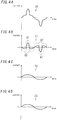
- FIGS. 4A, 4B, 4C, and 4D illustrate current waveforms of respective parts in a situation where the master device 21 performs voltage control and each of the slave devices 22, 23 performs current control in a different way from the embodiment described above.
- the current control performed by each of the slave devices 22, 23 uses a sinusoidal wave as the current waveform of the autonomous output, which is a major difference from the current control of this embodiment.
- FIG. 4A illustrates the waveform of a converted current I0.
- FIG. 4B illustrates the waveform of the current of the autonomous output (i.e., autonomous current) of the master device 21.
- FIG. 4C illustrates the waveform of the autonomous current 12 of the slave device 22.
- FIG. 4D illustrates the waveform of the autonomous current 13 of the slave device 23.
- the converted current 10 is a current required when a 200 V system should take charge of the total power load, and is represented by the sum of the respective autonomous currents I1, 12, and I3 of the master device 21 and slave devices 22,23.
- the second load 72 includes a capacitive load (such as a capacitor input load). Therefore, the converted current 10 steeply rises in the vicinity of a voltage peak and has a distorted waveform. If each of the slave devices 22, 23 performs current control using a sinusoidal wave as the current waveform of the autonomous output, then the master device 21 may take charge of most of the waveform distortion component, thus possibly causing a bias in output between the master device 21 and the slave devices 22, 23. For example, if the autonomous current I1 of the master device 21 takes charge of most of the waveform distortion component of the converted current 10, then the autonomous current I1 will be distorted as shown in FIG. 4B to be an overcurrent (as in the regions X1 shown in FIG.
- the autonomous current I1 of the master device 21 may have an opposite polarity from the converted current's 10 (as in the regions X2 in FIG. 4B ), thus possibly negatively affecting the system's safety.
- the master device 21 performs voltage control and each of the slave devices 22, 23 performs current control by taking charge of an evenly divided portion of the converted current 10 as described above.
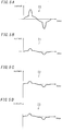
- FIGS. 5A, 5B, 5C, and 5D illustrate current waveforms of respective parts in a situation where the master device 21 performs voltage control and each of the slave devices 22, 23 performs current control by taking charge of an evenly divided portion of a converted current I0.
- FIG. 5A illustrates the waveform of a converted current I0.
- FIG. 5B illustrates the waveform of the autonomous current I1 of the master device 21.
- FIG. 5C illustrates the waveform of the autonomous current I2 of the slave device 22.
- FIG. 5D illustrates the waveform of the autonomous current I3 of the slave device 23.
- the second load 72 also includes a capacitive load. Therefore, the converted current T0 steeply rises in the vicinity of a voltage peak and has a distorted waveform.
- making the master device 21 perform the voltage control described above and making each of the slave devices 22, 23 perform current control by taking charge of an evenly divided portion of the converted current 10 allows the respective autonomous currents I1, I2, and I3 of the master device 21 and the slave devices 22, 23 to have approximately the same current value and waveform. As a result, the autonomous currents I1, I2, and I3 become hardly biased. That is to say, each of the slave devices 22, 23 sets the target current such that the respective power storage devices 2 in the system take charge of evenly divided portions of the converted current I0.
- the autonomous currents I1, I2, and I3 also almost evenly take charge of the waveform distortion component of the converted current I0, thus reducing the frequency of occurrence of the charging mode in which the autonomous currents have an opposite polarity from the converted current's 10. That is to say, if a plurality of autonomously operating power storage devices 2 are operating in parallel with each other, the power storage system according to this embodiment is able to reduce the degree of bias in the load placed on the respective power storage devices 2.
- the master device 21 also performs the power grid interconnected operation by performing the voltage control described above, and each of the slave devices 22, 23 also performs the power grid interconnected operation by performing the current control described above.
- the master device 21 may perform the power grid interconnected operation by performing the current control described above. In that case, the master device 21 is also allowed to acquire the measured data of the load currents I11 and I12 flowing through the first and second voltage lines L31 and L32, respectively.
- the power storage device 2 connected to the primary-side terminal of the transformer 5 does not have to be the master device 21 but may also be the slave device 22 or 23. In that case, the master device 21 will be connected to the secondary-side terminal of the transformer 5. Even in such an alternative embodiment, the same advantages as the ones described above are also achievable by having the master device 21 perform the voltage control and by having the slave devices 22, 23 perform the current control in the same way as described above.
- the control unit 2d of each of the slave devices 22, 23 is able to communicate with the master device 21 via the communications unit 2c, and transmits remaining capacity data to the master device 21 at regular intervals.
- the "remaining capacity data" represents the charge level of the storage battery 2a.
- the control unit 2d of the master device 21 is able to learn about the currently remaining capacities (charge levels) of the slave devices 22, 23. Thus, it is recommended that the control unit 2d of the master device 21 calculate a weighting factor for adding weight to the respective target currents of the slave devices 22, 23 based on the respective remaining capacity data of its own device and the slave devices 22, 23.
- the control unit 2d of the master device 21 calculates a weighting factor ⁇ based on the respective remaining capacity data of its own device and the slave devices 22, 23. More specifically, the control unit 2d of the master device 21 calculates the ratio of the remaining capacity of each of the slave devices 22, 23 to that of its own device [slave device's remaining capacity/master device's remaining capacity] as the weighting factor ⁇ . That is to say, the weighting factor ⁇ 2 for the slave device 22 is given by [slave device's 22 remaining capacity/master device's 21 remaining capacity], while the weighting factor ⁇ 3 for the slave device 23 is given by [slave device's 23 remaining capacity/master device's 21 remaining capacity]. Then, the control unit 2d of the master device 21 transmits data about the weighting factor ⁇ 2 to the slave device 22, and also transmits data about the weighting factor ⁇ 3 to the slave device 23.
- the control unit 2d of the slave device 22 divides the converted current by the number of the power storage devices 2, multiplies the quotient thus calculated by the weighting factor ⁇ 2, and sets the product thus obtained to be a target current.
- the control unit 2d of the slave device 23 divides the converted current by the number of the power storage devices 2, multiplies the quotient thus calculated by the weighting factor ⁇ 3, and sets the product thus obtained to be a target current.
- each of the plurality of power storage devices 2 further includes a communications unit 2c with the ability to communicate with the other power storage devices 2.
- Each of the slave devices 22, 23 transmits remaining capacity data, representing the remaining capacity of its own device's storage battery 2a, to the master device 21.
- the master device 21 sets a factor ⁇ , which increases as the remaining capacity increases, for each of the power storage devices 2, and transmits data about associated factors ⁇ to the respective slave devices 22, 23.
- Each of the slave devices 22, 23 further includes a control unit 2d for converting the measured data of the load currents I11 and I12 into a converted current corresponding to the line voltage of 200 V between the first and second voltage lines L31 and L32.
- the control unit 2d of the slave devices 22, 23 divides the converted current by the number of the power storage devices 2, multiplies the quotient thus calculated by the factor ⁇ , and sets the product thus obtained to be a target current.
- the amount of the autonomous current supplied from a power storage device 2 with a relatively large remaining capacity increases, while the amount of the autonomous current supplied from a power storage device 2 with a relatively small remaining capacity decreases.
- This allows the power storage system 100 to reduce the bias in output AC power between the respective power storage devices 2 and to make the remaining capacities of the storage batteries 2a of the respective power storage devices 2 as uniform as possible as current loads corresponding to the remaining capacities of the respective power storage devices 2.
- a power storage system (100) includes a plurality of power storage devices (2) and a transformer (5).
- Each of the plurality of power storage devices (2) includes a storage battery (2a) and a power conditioner (2b) configured to convert DC power of the storage battery (2a) into two-wire AC power and output the two-wire AC power, and is switchable between a power grid interconnected operation and an autonomous operation.
- the transformer (5) includes a primary winding (51) and a secondary winding (52). A two-wire AC voltage is applied to the primary winding (51).
- the secondary winding (52) is connected to a single-phase three-wire autonomous power line (87) (power line), to which a second load (72) (load) is connected.
- the autonomous power line (87) includes a first voltage line (L31), a second voltage line (L32), and a neutral line (L30).
- the power conditioner (2b) of any one (2) of the plurality of power storage devices (2) is configured to apply a two-wire AC voltage to be output during the autonomous operation to the primary winding (51).
- the power conditioner (2b) of the rest of the plurality of power storage devices (2) has an output connected to the first voltage line and the second voltage line (L31, L32) during the autonomous operation. If each of the plurality of power storage devices (2) performs the autonomous operation, any one (2) of the plurality of power storage devices (2) is configured to serve as a master device (21), while the rest of the power storage devices (2), other than the one (2) serving as the master device (21), is configured to serve as at least one slave device (22, 23).
- the power conditioner (2b) of the master device (21) is configured to perform voltage control of controlling an AC voltage output during the autonomous operation toward a target voltage.
- the at least one slave device (22, 23) further includes a data acquisition unit (2e) configured to acquire measured data of a first current (load current I11) flowing through the first voltage line (L31) and a second current (load current I12) flowing through the second voltage line (L32).
- the power conditioner (2b) of the at least one slave device (22, 23) is configured to perform current control of controlling an output current toward a target current, which has been determined based on the measured data of the first current and the second current, during the autonomous operation.
- the power storage system (100) includes the transformer (5) for converting two-wire power into single-phase three-wire power.
- the autonomous output of one power storage device (2) is input to a primary-side terminal of the transformer (5) and converted by the transformer (5) into single-phase three-wire power.
- the autonomous output of each of the other power storage device(s) (2) is connected to the secondary-side terminal of the transformer (5) so as to be directly supplied to the single-phase three-wire power line.
- the respective autonomous outputs of all of the power storage devices (2) could be connected to the primary-side terminal of a single transformer so that all autonomous outputs of all of the power storage devices (2) would be converted by the transformer into single-phase three-wire power.
- the capacity of the transformer should correspond to the sum of all autonomous outputs of all of the power storage devices (2), which would cause an increase in the size and cost of the transformer.
- the power storage system (100) according to the first aspect only the autonomous output of a single power storage device (2) is connected to the primary-side terminal of the transformer (5), and the autonomous output of the other power storage device(s) (2) is connected to the secondary-side terminal of the transformer (5).
- This allows the transformer (5) to have a capacity corresponding to the autonomous output of the single power storage device (2).
- the power storage system (100) according to the first aspect provides a simplified system configuration by reducing the size and cost of the transformer (5).
- the power storage system (100) according to the first aspect having such a simple system configuration, operates a plurality of power storage devices (2) in parallel with each other, thus contributing to increasing the capacity of single-phase three-wire power.
- the power storage system (100) allows for supplying single-phase three-wire power by operating the plurality of power storage devices (2) in parallel with each other and increasing the capacity of the single-phase three-wire power easily using a simple system configuration.
- the power conditioner (2b) of the master device (21) may be configured to apply the two-wire AC voltage to be output during the autonomous operation to the primary winding (51).
- the power conditioner (2b) of the at least one slave device (22, 23) may have an output connected to the first voltage line and the second voltage line (L31, L32) during the autonomous operation.
- the autonomous output of the master device (21) is input to the primary-side terminal of the transformer (5), and converted by the transformer (5) into single-phase three-wire power.
- the autonomous output of the at least one slave device (22, 23) is connected to the secondary-side terminal of the transformer (5) so as to be directly supplied to the single-phase three-wire power line. That is to say, only the autonomous output of the master device (21) is connected to the primary-side terminal of the transformer (5), and the autonomous output of the at least one slave device (22, 23) is connected to the secondary-side terminal of the transformer (5). This allows the transformer (5) to have a capacity corresponding to the autonomous output of the master device (21).
- the power storage system (100) provides a simplified system configuration by reducing the size and cost of the transformer (5).
- the power storage system (100) having such a simple system configuration, operates a plurality of power storage devices (2) in parallel with each other, thus contributing to increasing the capacity of the single-phase three-wire power.
- the at least one slave device (22, 23) may further include a control unit (2d) configured to convert the measured data of the first current and the second current into a converted current, corresponding to a line voltage of 200 V between the first voltage line and the second voltage line (L31, L32), and calculate the target current by dividing the converted current.
- a control unit (2d) configured to convert the measured data of the first current and the second current into a converted current, corresponding to a line voltage of 200 V between the first voltage line and the second voltage line (L31, L32), and calculate the target current by dividing the converted current.
- a power storage system (100) according to the third aspect is able to set the target current of the at least one slave device (22, 23) appropriately based on the converted current.
- control unit (2d) may be configured to calculate the target current by dividing the converted current by the number of the plurality of power storage devices (2).
- the target current is determined uniformly based on the converted current and the number of the plurality of power storage devices (22), and the at least one slave device (22, 23) performs current control of controlling the output current toward the target current.
- the respective autonomous outputs of the plurality of power storage devices (2) are allowed to have substantially the same current value and waveform, and become hardly biased.
- a power storage device (2) according to the first aspect of the present invention is configured to be used in the power storage system (100) according to any one of the first through fourth aspects described above.
- the power storage device (2) allows for supplying single-phase three-wire power by operating a plurality of power storage devices (2) in parallel with each other and increasing the capacity of the single-phase three-wire power easily using a simple system configuration.
- An operation method for the power storage device is a method for operating a power storage device for use in a power storage system (100) including a plurality of power storage devices (2) and a transformer (5).
- Each of the plurality of power storage devices (2) includes a storage battery (2a) and a power conditioner (2b) configured to convert DC power of the storage battery (2a) into two-wire AC power and output the two-wire AC power, and is switchable between a power grid interconnected operation and an autonomous operation.
- the transformer (5) includes a primary winding (51) and a secondary winding (52). A two-wire AC voltage is applied to the primary winding (51).
- the secondary winding (52) is connected to a single-phase three-wire autonomous power line (87) (power line), to which a second load (72) (load) is connected.
- the autonomous power line (87) includes a first voltage line (L31), a second voltage line (L32), and a neutral line (L30).
- the power conditioner (2b) of any one (2) of the plurality of power storage devices (2) is configured to apply a two-wire AC voltage to be output during the autonomous operation to the primary winding (51).
- the power conditioner (2b) of the rest of the plurality of power storage devices (2) has an output connected to the first voltage line and the second voltage line (L31, L32) during the autonomous operation. If each of the plurality of power storage devices (2) performs the autonomous operation, any one of the plurality of power storage devices (2) is configured to serve as a master device (21), while the rest of the plurality of power storage devices (2), other than the one (2) serving as the master device (21), is configured to serve as at least one slave device (22, 23).
- the power conditioner (2b) of the master device (21) is configured to perform voltage control of controlling an AC voltage output during the autonomous operation toward a target voltage.
- the power conditioner (2b) of the at least one slave device (22, 23) is configured to perform current control of controlling an output current toward a target current that has been determined based on measured data of a first current and a second current (load currents I11, I12) flowing through the first voltage line and the second voltage line (L31, L32), respectively.
- An operation method for the power storage device allows for supplying single-phase three-wire power by operating a plurality of power storage devices (2) in parallel with each other and increasing the capacity of the single-phase three-wire power easily using a simple system configuration.
- each power storage device 2 includes a built-in computer and the function of the control unit 2d of the power storage device 2 described above is performed by making the computer execute a program.
- the computer includes, as major components, a device with a processor executing a program, an interface device for exchanging data with other devices, and a storage device for storing data.
- the device with a processor may be a central processing unit (CPU) or micro processing unit (MPU) provided separately from a semiconductor memory, or a microcomputer including a semiconductor memory as an integral component.
- a storage device with a short access time such as a semiconductor memory and a storage device with a large storage capacity such as a hard disk drive may be used in combination.
- the program may be provided as either having been pre-stored on some storage medium such as a computer-readable read-only memory (ROM) or an optical disc or being downloaded onto a storage medium over a broadband communications network such as the Internet.
- some storage medium such as a computer-readable read-only memory (ROM) or an optical disc
- ROM read-only memory
- optical disc or being downloaded onto a storage medium over a broadband communications network such as the Internet.
Landscapes
- Engineering & Computer Science (AREA)
- Power Engineering (AREA)
- Chemical Kinetics & Catalysis (AREA)
- Manufacturing & Machinery (AREA)
- Chemical & Material Sciences (AREA)
- Electrochemistry (AREA)
- General Chemical & Material Sciences (AREA)
- Emergency Management (AREA)
- Business, Economics & Management (AREA)
- Supply And Distribution Of Alternating Current (AREA)
- Charge And Discharge Circuits For Batteries Or The Like (AREA)
- Stand-By Power Supply Arrangements (AREA)
- Secondary Cells (AREA)
Abstract
Description
- The present invention generally relates to a power storage system, a power storage device, and an operation method for the power storage device.
- A system for supplying electric power to a load by operating a plurality of power storage devices in parallel with each other has been know in the art.
- For example, the system described in
Patent Literature 1 includes not only a first power storage circuit with a storage battery but also a second power storage circuit with an electric double layer capacitor. When the power consumption of an external load increases momentarily, the first power storage circuit supplies electric power after the second power storage circuit has supplied electric power. - Meanwhile, a power storage system allowing a plurality of power storage devices to operate in parallel with each other has also been know in the art.
- In such a power storage system, each power storage device outputs two-wire electric power. However, some users may need single-phase three-wire electric power. In addition, there is also a growing demand for increasing the capacity of single-phase three-wire power using a system with a simpler configuration.
- Patent Literature 1:
JP 2002-110210 A - It is therefore an object of the present invention to provide a power storage system, power storage device, and operation method for the power storage device allowing single-phase three-wire power to be supplied by operating a plurality of power storage devices in parallel with each other and also allowing the capacity of single-phase three-wire power to be increased easily with a simple system configuration.
- A power storage system according to an aspect of the present invention includes: a plurality of power storage devices, each of which includes a storage battery and a power conditioner configured to convert DC power of the storage battery into two-wire AC power and output the two-wire AC power and which is switchable between a power grid interconnected operation and an autonomous operation; and a transformer including a primary winding to which a two-wire AC voltage is applied and a secondary winding connected to a single-phase three-wire power line, a load being connected to the single-phase three-wire power line. The single-phase three-wire power line includes a first voltage line, a second voltage line, and a neutral line. The power conditioner of any one of the plurality of power storage devices is configured to apply a two-wire AC voltage to be output during the autonomous operation to the primary winding, and the power conditioner of the rest of the plurality of power storage devices has an output connected to the first voltage line and the second voltage line during the autonomous operation. If each of the plurality of power storage devices performs the autonomous operation, any one of the plurality of power storage devices is configured to serve as a master device, while the rest of the plurality of power storage devices, other than the one serving as the master device, is configured to serve as at least one slave device. The power conditioner of the master device is configured to perform voltage control of controlling an AC voltage output during the autonomous operation toward a target voltage. The at least one slave device further includes a data acquisition unit configured to acquire measured data of a first current flowing through the first voltage line and a second current flowing through the second voltage line. The power conditioner of the at least one slave device is configured to perform current control of controlling an output current toward a target current during the autonomous operation. The target current has been determined based on the measured data of the first current and the second current.
- A power storage device according to another aspect of the present invention is configured to be used in the power storage system described above.
- An operation method for a power storage device according to yet another aspect of the present invention is a method for operating a power storage device for use in a power storage system. The power storage system includes: a plurality of power storage devices, each of which includes a storage battery and a power conditioner configured to convert DC power of the storage battery into two-wire AC power and output the two-wire AC power and which is switchable between a power grid interconnected operation and an autonomous operation; and a transformer including a primary winding to which a two-wire AC voltage is applied and a secondary winding connected to a single-phase three-wire power line. A load is connected to the single-phase three-wire power line. The single-phase three-wire power line includes a first voltage line, a second voltage line, and a neutral line. The power conditioner of any one of the plurality of power storage devices is configured to apply a two-wire AC voltage to be output during the autonomous operation to the primary winding, and the power conditioner of the rest of the plurality of power storage devices has an output connected to the first voltage line and the second voltage line during the autonomous operation. If each of the plurality of power storage devices performs the autonomous operation, any one of the plurality of power storage devices is configured to serve as a master device, while the rest of the plurality of power storage devices, other than the one serving as the master device, is configured to serve as at least one slave device. The power conditioner of the master device is configured to perform voltage control of controlling an AC voltage output during the autonomous operation toward a target voltage. The power conditioner of the at least one slave device is configured to perform current control of controlling an output current toward a target current that has been determined based on measured data of a first current and a second current flowing through the first voltage line and the second voltage line, respectively.
-
-
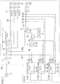
FIG. 1 is a block diagram illustrating a configuration for a power storage system according to an embodiment; -
FIG. 2 is a block diagram illustrating a configuration for a power storage device according to the embodiment; -
FIG. 3 schematically illustrates how a second load may be connected to a plurality of power storage devices performing an autonomous operation according to the embodiment; -
FIGS. 4A, 4B, 4C, and 4D are waveform charts showing the current waveforms of respective parts in a situation where an autonomous output control is performed in a different way from the embodiment; and -
FIGS. 5A, 5B, 5C, and 5D are waveform charts showing the current waveforms of respective parts in a situation where an autonomous output control is performed in accordance with the embodiment. - An embodiment of the present invention will now be described with reference to the accompanying drawings.
- The following embodiment generally relates to a power storage system, a power storage device, and an operation method for the power storage device, and more particularly relate to a power storage system, power storage device, and operation method for the power storage device in which a plurality of power storage devices are operated in parallel with each other.
- A
power storage system 100 according to an embodiment of the present invention has the configuration shown inFIG. 1 . Thispower storage system 100 may be used in a building supplied with utility power from a utility power company. Examples of such buildings include a dwelling unit of a multi-family dwelling house, a single-family house, a factory, and an office building. Thepower storage system 100 includes, as its essential components, a plurality ofpower storage devices 2 and atransformer 5. Thepower storage system 100 further includes adistribution board 1,switchboards controller 4. Although these power storage devices are generally designated herein by thereference numeral 2 as a matter of principle, thepower storage devices 2 will be sometimes designated herein by thereference numerals - The
distribution board 1 is connected to atrunk power line 81 extended into the building and is supplied with single-phase three-wire 200 V/100 V utility power from a power company'sutility power supply 9 through thetrunk power line 81, which is composed of two voltage lines and one grounded neutral line. In thedistribution board 1, housed are a mainspower supply breaker 1a,branch breakers 1b, and a distributionpower supply breaker 1c. Thetrunk power line 81 is connected to each of the plurality ofbranch breakers 1b and the distributionpower supply breaker 1c via the mainspower supply breaker 1a. - The
trunk power line 81 branches into a plurality ofbranch power lines 82 via therespective branch breakers 1b. Afirst load 71 is connected to each of thebranch power lines 82. Thefirst load 71 is composed of at least oneelectric appliance 710 such as a lighting fixture, an air conditioner, or any other consumer electronic appliance. Each of thebranch power lines 82 supplies an AC power of 200 V or 100 V to its associatedfirst load 71. - The
trunk power line 81 also branches into abranch power line 82a via anotherbranch breaker 1b. Thebranch power line 82a is connected to theswitchboard 31. Thisbranch power line 82a supplies a single-phase three-wire AC power of 200 V/100 V. - This power storage system includes the plurality of
power storage devices 2, any one of which serves as a master device and the others of which serve as slave devices. According to this embodiment, each of thepower storage devices 2 is provided with a selector such as a switch so as to function as either a master device or a slave device as the selector is turned. That is to say,power storage devices 2 of the same type are used as the master and slave devices according to this embodiment. In an alternative embodiment, a dedicated power storage device may be used as the master device and dedicated power storage devices may be used as the slave devices. - In the following description, the
power storage device 21 is supposed to be a master device and thepower storage devices - Each of the plurality of power storage devices 2 (functioning as the
master device 21 and theslave devices 22, 23) includes astorage battery 2a, apower conditioner 2b, acommunications unit 2c, acontrol unit 2d, and adata acquisition unit 2e as shown inFIG. 2 . - The
storage battery 2a may be implemented as a secondary battery such as a lithium-ion battery, and is connected to thepower conditioner 2b. Thepower conditioner 2b has an AC/DC conversion function and a DC/AC conversion function. The AC/DC conversion function refers herein to the function of converting AC power into DC power to charge thestorage battery 2a with the DC power. The DC/AC function refers herein to the function of converting the DC power of thestorage battery 2a into AC power and outputting the AC power. - The
power conditioner 2b suitably charges thestorage battery 2a when the charge level of thestorage battery 2a decreases to a preset value. Optionally, thepower conditioner 2b may be configured to charge thestorage battery 2a at regular intervals (e.g., at midnight) with power. - The
power grid interconnector 2f of thepower conditioner 2b receives utility power from theutility power supply 9 via the distributionpower supply breaker 1c and anAC power line 83. Thepower conditioner 2b may convert the utility power received into DC power and charge thestorage battery 2a with the DC power. - Also, the discharge power of the
storage battery 2a is supplied to thepower conditioner 2b, and is converted by thepower conditioner 2b into two-wire 200 V AC power (i.e., with a line voltage of 200 V). Thispower conditioner 2b is switchable between a power grid interconnected operation and an autonomous operation. By detecting the AC voltage input to thepower grid interconnector 2f, thepower conditioner 2b determines whether the system is operating normally or causing a power failure. In the normal state, theutility power supply 9 supplies utility power. On the other hand, in the power failure state, the supply of utility power from theutility power supply 9 is discontinued. - More specifically, in the normal state in which the
utility power supply 9 is energized, thepower conditioner 2b performs a power grid interconnected operation. On the other hand, when theutility power supply 9 causes a power failure, thepower conditioner 2b performs an autonomous operation. While performing the power grid interconnected operation, thepower conditioner 2b outputs a two-wire 200 V AC power, generated from the discharge power of thestorage battery 2a, through thepower grid interconnector 2f while being interconnected with the utility power supply 9 (utility power grid). On the other hand, during the autonomous operation, thepower conditioner 2b outputs two-wire 200 V AC power, generated from the discharge power of thestorage battery 2a, through theautonomous connector 2g without being interconnected with the utility power grid. - In the following description, the AC power output from the
power grid interconnector 2f will be hereinafter referred to as a "power grid output" and the AC power output from theautonomous connector 2g will be hereinafter referred to as an "autonomous output." - The
power grid interconnector 2f is also connected to theAC power line 83. The power grid output is supplied from theAC power line 83 through the distributionpower supply breaker 1c of thedistribution board 1 to thetrunk power line 81. Meanwhile, the power grid output is also supplied from thetrunk power line 81 through thebranch breakers 1b to thebranch power lines 82. Thepower conditioners 2b have a power grid interconnection function, which is a function for establishing power cooperation between the power grid output and the utility power supplied by theutility power supply 9. In this embodiment, theAC power line 83 is a two-wire power line for transmitting two-wire 200 V AC power, and two voltage lines of theAC power line 83 are connected to their associated two voltage lines of thetrunk power line 81. - The
autonomous connector 2g of themaster device 21 is connected to a two-wireAC power line 84. The autonomous output of themaster device 21 is output to theAC power line 84. The two-wireAC power line 84 is electrically connected to a three-wireAC power line 85 via thetransformer 5, which is an insulated transformer for converting two-wire 200 V AC power into single-phase three-wire 200 V/100 V AC power. Thistransformer 5 includes a primary winding 51 and a secondary winding 52. The two-wireAC power line 84 is connected to the primary winding 51, while the three-wireAC power line 85 is connected to the secondary winding 52. Theswitchboard 32 selectively connects or disconnects the three-wireAC power line 85 to/from another three-wireAC power line 86 to make these three-wireAC power lines switchboard 31 selectively connects a three-wireautonomous power line 87 to either thebranch power line 82a or theAC power line 86. Theautonomous power line 87 is composed of a first voltage line, a second voltage line, and a single grounded neutral line. Asecond load 72 is connected to theautonomous power line 87. Thesecond load 72 is composed of at least oneelectric appliance 720 such as a lighting fixture, an air conditioner, or any other consumer electronic appliance. - In this embodiment, the
trunk power line 81 is a three-wire power line for transmitting single-phase three-wire 200 V/100 V AC power. Each of thebranch power lines 82 is either a three-wire power line for transmitting single-phase three-wire 200 V/100 V AC power or a two-wire power line for transmitting two-wire 200 V/100 V AC power. Meanwhile, thebranch power line 82a is a three-wire power line for transmitting single-phase three-wire 200 V/100 V AC power. Each of theAC power lines AC power lines autonomous power line 87 is a three-wire power line for transmitting single-phase three-wire 200 V/100 V AC power. - The respective
autonomous connectors 2g of theslave devices AC power line 85. Each autonomous output of theslave devices AC power line 85, theswitchboard 32, theAC power line 86, and theswitchboard 31 to theautonomous power line 87. In this embodiment, the respective autonomous outputs of theslave devices AC power line 85. - The
controller 4 controls the respective switching states of theswitchboards controller 4 determines whether the system is operating normally or causing a power failure by detecting a voltage at the primary-side terminal of the mainspower supply breaker 1a, for example. On determining that the system is operating normally, thecontroller 4 controls the switching state of theswitchboard 31 to connect theautonomous power line 87 to thebranch power line 82a and to turn theswitchboard 32 OFF. On the other hand, on determining that the system is causing a power failure, thecontroller 4 controls the switching state of theswitchboard 31 to connect theautonomous power line 87 to theAC power line 86, and after thepower storage devices 2 have all been activated, turns theswitchboard 32 ON to make theAC power lines - In the normal operation state, the
autonomous power line 87 is connected by theswitchboard 31 to thebranch power line 82a, thus making the power line leading from thebranch power line 82a to theautonomous power line 87 electrically conductive and supplying the power on the trunk power line 81 (i.e., the sum of the utility power and the power grid output) to theautonomous power line 87. Furthermore, in the normal operation state, thetrunk power line 81 is cut off from the respectiveautonomous connectors 2g of theslave devices autonomous connectors 2g. - On the other hand, in the power failure state, the
autonomous power line 87 is connected by theswitchboard 31 to theAC power line 86, and theAC power line 86 is connected by theswitchboard 32 to theAC power line 85. This makes the power line leading from the respectiveautonomous connectors 2g of themaster device 21 andslave devices autonomous power line 87 electrically conductive, thus supplying the respective autonomous outputs of themaster device 21 andslave devices autonomous power line 87. - In the
power storage system 100, thefirst load 71 connected to thebranch power lines 82 is supplied with power only in the normal operation state in which theutility power supply 9 is energized. On the other hand, thesecond load 72 connected to theautonomous power line 87 is supplied with power both in the normal operation state where theutility power supply 9 is energized and in the state where theutility power supply 9 is causing a power failure. - The
autonomous power line 87 to which thesecond load 72 is electrically connected is composed of two voltage lines and a single grounded neutral line. Thisautonomous power line 87 is provided with current sensors 61-64, which measure load currents flowing through the respective voltage lines of theautonomous power line 87. Specifically, thevoltage sensor 61 measures a load current (hereinafter referred to as a "first current") flowing through the first voltage line and outputs resultant measured data to theslave device 22. Thevoltage sensor 62 measures a load current (hereinafter referred to as a "second current") flowing through the second voltage line and outputs resultant measured data to theslave device 22. Thevoltage sensor 63 measures the load current (i.e., the first current) flowing through the first voltage line and outputs resultant measured data to theslave device 23. Thevoltage sensor 64 measures the load current (i.e., the second current) flowing through the second voltage line and outputs resultant measured data to theslave device 23. Each of these current sensors 61-64 generates and outputs the measured data in every sampling period. - The
data acquisition unit 2e of each of theslave devices control unit 2d. - The
communications unit 2c of eachpower storage device 2 may communicate either wirelessly or through a cable with thecommunications unit 2c of any of the otherpower storage devices 2. Thecontrol unit 2d controls the communications carried out by thecommunications unit 2c. - Next, it will be described with reference to
FIG. 3 how thepower storage devices 2 perform an autonomous operation in the power failure state.FIG. 3 schematically illustrates only how the plurality ofpower storage devices 2 performing the autonomous operation are connected to thesecond load 72. - The
AC power line 84 connected to theautonomous connector 2g of themaster device 21 is composed of two wires, namely, the voltage lines L1, L2. The voltage line L1 is connected to one terminal of the primary winding 51 of thetransformer 5, while the voltage line L2 is connected to the other terminal of the primary winding 51 of thetransformer 5. Thetransformer 5 includes a secondary winding 52. One terminal of the secondary winding 52 is connected to the voltage line L11 of theAC power line 85, the other terminal of the secondary winding 52 is connected to the voltage line L12 of theAC power line 85, and a neutral point of the secondary winding 52 is connected to the neutral line L10 of theAC power line 85. - That is to say, the
transformer 5 converts two-wire 200 V AC power, supplied from theAC power line 84, into single-phase three-wire 200 V/100 V power and outputs the 200 V/100 V power to theAC power line 85. In this case, the line voltage between the voltage lines L11 and L12 becomes 200 V, the line voltage between the voltage line L11 and the neutral line L10 becomes 100 V, and the line voltage between the voltage line L12 and the neutral line L10 becomes 100 V. - The
autonomous connectors 2g of theslave devices AC power line 85. - The voltage line L11, voltage line L12, and neutral line L10 of the
AC power line 85 are respectively electrically connected to the first voltage line L31, second voltage line L32, and neutral line L30 of theautonomous power line 87 through theswitchboard 32, theAC power line 86, and theswitchboard 31. That is to say, the line voltage between the first and second voltage lines L31 and L32 becomes 200 V, the line voltage between the first voltage line L31 and the neutral line L30 becomes 100 V, and the line voltage between the second voltage line L32 and the neutral line L30 becomes 100 V. - That is to say, the autonomous outputs of the
respective power conditioners 2b of themaster device 21 andslave devices autonomous power line 87 in the autonomous operation state. In other words, themaster device 21 and theslave devices FIG. 3 , thesecond load 72 is electrically connected between the first and second voltage lines L31 and L32. - During both of the power grid interconnected operation and the autonomous operation, the
control unit 2d of each of themaster device 21 andslave devices power storage devices 2 via thecommunications unit 2c. Thecontrol unit 2d is able to recognize the number ofpower storage devices 2 in thepower storage system 100 based on a signal received from anotherpower storage device 2, and retains data about the number ofpower storage devices 2 in thepower storage system 100. - When the
master device 21 and theslave devices control unit 2d of themaster device 21 instructs thepower conditioner 2b to perform a constant voltage operation. More specifically, thecontrol unit 2d of themaster device 21 notifies thepower conditioner 2b of a target voltage. Thepower conditioner 2b, having been instructed to perform a constant voltage operation, performs voltage control such that the voltage of the autonomous output agrees with a target voltage, which is set to be the nominal voltage of utility power, e.g., 200 V in this example. - In each of the
slave devices control unit 2d instructs thepower conditioner 2b to perform a constant current operation. More specifically, thecontrol unit 2d of each of theslave devices power conditioner 2b of a target current. Thepower conditioner 2b, having been instructed to perform a constant current operation, performs current control such that the current of the autonomous output agrees with the target current. In thepower conditioner 2b which has been instructed to perform a constant current operation, the voltage of the autonomous output is in the vicinity of the nominal voltage of utility power, e.g., 200 V. - Making the
master device 21 and theslave devices slave devices master device 21 has started performing the autonomous operation for the purpose of voltage control. Alternatively, making themaster device 21 andslave devices - Specifically, the
control unit 2d of each of theslave devices control unit 2d of each of theslave devices FIG. 3 . - As used herein, the "converted current" is obtained by converting the measured data of the load currents I11 and I12 into a current corresponding to the line voltage of 200 V between the first and second voltage lines L31 and L32. That is to say, the converted current is an amount of current allowing the electric power required by the
second load 72 for a two-wire 200 V power line with a line voltage of 200 V (i.e., the overall power consumed) to be supplied. Thecontrol unit 2d of each of theslave devices - Alternatively, the
control unit 2d of each of theslave devices - That is to say, each of the
slave devices power storage devices 2 in the system take charge of an evenly divided portion the total power load. Thus, the respective autonomous outputs of theslave devices master device 21 performing the voltage control also comes to have the same current value and the same waveform as the respective autonomous outputs of theslave devices -
FIGS. 4A, 4B, 4C, and 4D illustrate current waveforms of respective parts in a situation where themaster device 21 performs voltage control and each of theslave devices slave devices -
FIG. 4A illustrates the waveform of a converted current I0.FIG. 4B illustrates the waveform of the current of the autonomous output (i.e., autonomous current) of themaster device 21.FIG. 4C illustrates the waveform of the autonomous current 12 of theslave device 22.FIG. 4D illustrates the waveform of the autonomous current 13 of theslave device 23. Note that the converted current 10 is a current required when a 200 V system should take charge of the total power load, and is represented by the sum of the respective autonomous currents I1, 12, and I3 of themaster device 21 andslave devices - In this case, the
second load 72 includes a capacitive load (such as a capacitor input load). Therefore, the converted current 10 steeply rises in the vicinity of a voltage peak and has a distorted waveform. If each of theslave devices master device 21 may take charge of most of the waveform distortion component, thus possibly causing a bias in output between themaster device 21 and theslave devices master device 21 takes charge of most of the waveform distortion component of the converted current 10, then the autonomous current I1 will be distorted as shown inFIG. 4B to be an overcurrent (as in the regions X1 shown inFIG. 4B ), thus causing themaster device 21 to lose the stability of its operation. In addition, in some charging modes, the autonomous current I1 of themaster device 21 may have an opposite polarity from the converted current's 10 (as in the regions X2 inFIG. 4B ), thus possibly negatively affecting the system's safety. - Thus, according to this embodiment, the
master device 21 performs voltage control and each of theslave devices -
FIGS. 5A, 5B, 5C, and 5D illustrate current waveforms of respective parts in a situation where themaster device 21 performs voltage control and each of theslave devices FIG. 5A illustrates the waveform of a converted current I0.FIG. 5B illustrates the waveform of the autonomous current I1 of themaster device 21.FIG. 5C illustrates the waveform of the autonomous current I2 of theslave device 22.FIG. 5D illustrates the waveform of the autonomous current I3 of theslave device 23. - In this case, the
second load 72 also includes a capacitive load. Therefore, the converted current T0 steeply rises in the vicinity of a voltage peak and has a distorted waveform. However, making themaster device 21 perform the voltage control described above and making each of theslave devices master device 21 and theslave devices slave devices power storage devices 2 in the system take charge of evenly divided portions of the converted current I0. - Thus, the autonomous currents I1, I2, and I3 also almost evenly take charge of the waveform distortion component of the converted current I0, thus reducing the frequency of occurrence of the charging mode in which the autonomous currents have an opposite polarity from the converted current's 10. That is to say, if a plurality of autonomously operating
power storage devices 2 are operating in parallel with each other, the power storage system according to this embodiment is able to reduce the degree of bias in the load placed on the respectivepower storage devices 2. - In addition, even in the normal operation state, the
master device 21 also performs the power grid interconnected operation by performing the voltage control described above, and each of theslave devices slave devices master device 21 may perform the power grid interconnected operation by performing the current control described above. In that case, themaster device 21 is also allowed to acquire the measured data of the load currents I11 and I12 flowing through the first and second voltage lines L31 and L32, respectively. - The
power storage device 2 connected to the primary-side terminal of thetransformer 5 does not have to be themaster device 21 but may also be theslave device master device 21 will be connected to the secondary-side terminal of thetransformer 5. Even in such an alternative embodiment, the same advantages as the ones described above are also achievable by having themaster device 21 perform the voltage control and by having theslave devices - The
control unit 2d of each of theslave devices master device 21 via thecommunications unit 2c, and transmits remaining capacity data to themaster device 21 at regular intervals. As used herein, the "remaining capacity data" represents the charge level of thestorage battery 2a. Thecontrol unit 2d of themaster device 21 is able to learn about the currently remaining capacities (charge levels) of theslave devices control unit 2d of themaster device 21 calculate a weighting factor for adding weight to the respective target currents of theslave devices slave devices - The
control unit 2d of themaster device 21 calculates a weighting factor α based on the respective remaining capacity data of its own device and theslave devices control unit 2d of themaster device 21 calculates the ratio of the remaining capacity of each of theslave devices slave device 22 is given by [slave device's 22 remaining capacity/master device's 21 remaining capacity], while the weighting factor α3 for theslave device 23 is given by [slave device's 23 remaining capacity/master device's 21 remaining capacity]. Then, thecontrol unit 2d of themaster device 21 transmits data about the weighting factor α2 to theslave device 22, and also transmits data about the weighting factor α3 to theslave device 23. - The
control unit 2d of theslave device 22 divides the converted current by the number of thepower storage devices 2, multiplies the quotient thus calculated by the weighting factor α2, and sets the product thus obtained to be a target current. On the other hand, thecontrol unit 2d of theslave device 23 divides the converted current by the number of thepower storage devices 2, multiplies the quotient thus calculated by the weighting factor α3, and sets the product thus obtained to be a target current. - That is to say, each of the plurality of
power storage devices 2 further includes acommunications unit 2c with the ability to communicate with the otherpower storage devices 2. Each of theslave devices storage battery 2a, to themaster device 21. In response, in accordance with the remaining capacity data of theslave devices master device 21 sets a factor α, which increases as the remaining capacity increases, for each of thepower storage devices 2, and transmits data about associated factors α to therespective slave devices slave devices control unit 2d for converting the measured data of the load currents I11 and I12 into a converted current corresponding to the line voltage of 200 V between the first and second voltage lines L31 and L32. Thecontrol unit 2d of theslave devices power storage devices 2, multiplies the quotient thus calculated by the factor α, and sets the product thus obtained to be a target current. - That is to say, the amount of the autonomous current supplied from a
power storage device 2 with a relatively large remaining capacity increases, while the amount of the autonomous current supplied from apower storage device 2 with a relatively small remaining capacity decreases. This allows thepower storage system 100 to reduce the bias in output AC power between the respectivepower storage devices 2 and to make the remaining capacities of thestorage batteries 2a of the respectivepower storage devices 2 as uniform as possible as current loads corresponding to the remaining capacities of the respectivepower storage devices 2. - As can be seen from the foregoing description of embodiments, a power storage system (100) according to a first aspect of the present invention includes a plurality of power storage devices (2) and a transformer (5). Each of the plurality of power storage devices (2) includes a storage battery (2a) and a power conditioner (2b) configured to convert DC power of the storage battery (2a) into two-wire AC power and output the two-wire AC power, and is switchable between a power grid interconnected operation and an autonomous operation. The transformer (5) includes a primary winding (51) and a secondary winding (52). A two-wire AC voltage is applied to the primary winding (51). The secondary winding (52) is connected to a single-phase three-wire autonomous power line (87) (power line), to which a second load (72) (load) is connected. The autonomous power line (87) includes a first voltage line (L31), a second voltage line (L32), and a neutral line (L30).
- The power conditioner (2b) of any one (2) of the plurality of power storage devices (2) is configured to apply a two-wire AC voltage to be output during the autonomous operation to the primary winding (51). The power conditioner (2b) of the rest of the plurality of power storage devices (2) has an output connected to the first voltage line and the second voltage line (L31, L32) during the autonomous operation. If each of the plurality of power storage devices (2) performs the autonomous operation, any one (2) of the plurality of power storage devices (2) is configured to serve as a master device (21), while the rest of the power storage devices (2), other than the one (2) serving as the master device (21), is configured to serve as at least one slave device (22, 23). The power conditioner (2b) of the master device (21) is configured to perform voltage control of controlling an AC voltage output during the autonomous operation toward a target voltage. The at least one slave device (22, 23) further includes a data acquisition unit (2e) configured to acquire measured data of a first current (load current I11) flowing through the first voltage line (L31) and a second current (load current I12) flowing through the second voltage line (L32). The power conditioner (2b) of the at least one slave device (22, 23) is configured to perform current control of controlling an output current toward a target current, which has been determined based on the measured data of the first current and the second current, during the autonomous operation.
- The power storage system (100) according to the first aspect includes the transformer (5) for converting two-wire power into single-phase three-wire power. The autonomous output of one power storage device (2) is input to a primary-side terminal of the transformer (5) and converted by the transformer (5) into single-phase three-wire power. The autonomous output of each of the other power storage device(s) (2) is connected to the secondary-side terminal of the transformer (5) so as to be directly supplied to the single-phase three-wire power line.
- Meanwhile, the respective autonomous outputs of all of the power storage devices (2) could be connected to the primary-side terminal of a single transformer so that all autonomous outputs of all of the power storage devices (2) would be converted by the transformer into single-phase three-wire power. In that case, however, the capacity of the transformer should correspond to the sum of all autonomous outputs of all of the power storage devices (2), which would cause an increase in the size and cost of the transformer.
- In contrast, in the power storage system (100) according to the first aspect, only the autonomous output of a single power storage device (2) is connected to the primary-side terminal of the transformer (5), and the autonomous output of the other power storage device(s) (2) is connected to the secondary-side terminal of the transformer (5). This allows the transformer (5) to have a capacity corresponding to the autonomous output of the single power storage device (2). Thus, the power storage system (100) according to the first aspect provides a simplified system configuration by reducing the size and cost of the transformer (5). In addition, the power storage system (100) according to the first aspect, having such a simple system configuration, operates a plurality of power storage devices (2) in parallel with each other, thus contributing to increasing the capacity of single-phase three-wire power.
- That is to say, the power storage system (100) according to the first aspect allows for supplying single-phase three-wire power by operating the plurality of power storage devices (2) in parallel with each other and increasing the capacity of the single-phase three-wire power easily using a simple system configuration.
- In a power storage system (100) according to a second aspect of the present invention, which is dependent on the first aspect, the power conditioner (2b) of the master device (21) may be configured to apply the two-wire AC voltage to be output during the autonomous operation to the primary winding (51). The power conditioner (2b) of the at least one slave device (22, 23) may have an output connected to the first voltage line and the second voltage line (L31, L32) during the autonomous operation.
- In the power storage system (100) according to the second aspect, the autonomous output of the master device (21) is input to the primary-side terminal of the transformer (5), and converted by the transformer (5) into single-phase three-wire power. The autonomous output of the at least one slave device (22, 23) is connected to the secondary-side terminal of the transformer (5) so as to be directly supplied to the single-phase three-wire power line. That is to say, only the autonomous output of the master device (21) is connected to the primary-side terminal of the transformer (5), and the autonomous output of the at least one slave device (22, 23) is connected to the secondary-side terminal of the transformer (5). This allows the transformer (5) to have a capacity corresponding to the autonomous output of the master device (21). Thus, the power storage system (100) provides a simplified system configuration by reducing the size and cost of the transformer (5). In addition, the power storage system (100), having such a simple system configuration, operates a plurality of power storage devices (2) in parallel with each other, thus contributing to increasing the capacity of the single-phase three-wire power.
- In a power storage system (100) according to a third aspect of the present invention, which is dependent on the first or second aspect, the at least one slave device (22, 23) may further include a control unit (2d) configured to convert the measured data of the first current and the second current into a converted current, corresponding to a line voltage of 200 V between the first voltage line and the second voltage line (L31, L32), and calculate the target current by dividing the converted current.
- A power storage system (100) according to the third aspect is able to set the target current of the at least one slave device (22, 23) appropriately based on the converted current.
- In a power storage system (100) according to a fourth aspect of the present invention, which is dependent on the third aspect, the control unit (2d) may be configured to calculate the target current by dividing the converted current by the number of the plurality of power storage devices (2).
- In the power storage system (100) according to the fourth aspect, the target current is determined uniformly based on the converted current and the number of the plurality of power storage devices (22), and the at least one slave device (22, 23) performs current control of controlling the output current toward the target current. Thus, the respective autonomous outputs of the plurality of power storage devices (2) are allowed to have substantially the same current value and waveform, and become hardly biased.
- A power storage device (2) according to the first aspect of the present invention is configured to be used in the power storage system (100) according to any one of the first through fourth aspects described above.
- The power storage device (2) according to the first aspect allows for supplying single-phase three-wire power by operating a plurality of power storage devices (2) in parallel with each other and increasing the capacity of the single-phase three-wire power easily using a simple system configuration.
- An operation method for the power storage device according to the first aspect of the present invention is a method for operating a power storage device for use in a power storage system (100) including a plurality of power storage devices (2) and a transformer (5). Each of the plurality of power storage devices (2) includes a storage battery (2a) and a power conditioner (2b) configured to convert DC power of the storage battery (2a) into two-wire AC power and output the two-wire AC power, and is switchable between a power grid interconnected operation and an autonomous operation. The transformer (5) includes a primary winding (51) and a secondary winding (52). A two-wire AC voltage is applied to the primary winding (51). The secondary winding (52) is connected to a single-phase three-wire autonomous power line (87) (power line), to which a second load (72) (load) is connected. The autonomous power line (87) includes a first voltage line (L31), a second voltage line (L32), and a neutral line (L30).
- The power conditioner (2b) of any one (2) of the plurality of power storage devices (2) is configured to apply a two-wire AC voltage to be output during the autonomous operation to the primary winding (51). The power conditioner (2b) of the rest of the plurality of power storage devices (2) has an output connected to the first voltage line and the second voltage line (L31, L32) during the autonomous operation. If each of the plurality of power storage devices (2) performs the autonomous operation, any one of the plurality of power storage devices (2) is configured to serve as a master device (21), while the rest of the plurality of power storage devices (2), other than the one (2) serving as the master device (21), is configured to serve as at least one slave device (22, 23). The power conditioner (2b) of the master device (21) is configured to perform voltage control of controlling an AC voltage output during the autonomous operation toward a target voltage. The power conditioner (2b) of the at least one slave device (22, 23) is configured to perform current control of controlling an output current toward a target current that has been determined based on measured data of a first current and a second current (load currents I11, I12) flowing through the first voltage line and the second voltage line (L31, L32), respectively.
- An operation method for the power storage device according to the first aspect allows for supplying single-phase three-wire power by operating a plurality of power storage devices (2) in parallel with each other and increasing the capacity of the single-phase three-wire power easily using a simple system configuration.
- Note that each
power storage device 2 includes a built-in computer and the function of thecontrol unit 2d of thepower storage device 2 described above is performed by making the computer execute a program. The computer includes, as major components, a device with a processor executing a program, an interface device for exchanging data with other devices, and a storage device for storing data. The device with a processor may be a central processing unit (CPU) or micro processing unit (MPU) provided separately from a semiconductor memory, or a microcomputer including a semiconductor memory as an integral component. As the storage device, a storage device with a short access time such as a semiconductor memory and a storage device with a large storage capacity such as a hard disk drive may be used in combination. - The program may be provided as either having been pre-stored on some storage medium such as a computer-readable read-only memory (ROM) or an optical disc or being downloaded onto a storage medium over a broadband communications network such as the Internet.
- Although the present invention has been described with reference to exemplary embodiments, those embodiments should not be construed as limiting but numerous modifications or variations can be readily made by those skilled in the art depending on their design choice or any other factor without departing from the true spirit and scope of the invention as defined by the appended claims.
-
- 100
- Power Storage System
- 1
- Distribution Board
- 2
- Power Storage Device
- 21
- Master Device
- 22, 23
- Slave Device
- 2a
- Storage Battery
- 2b
- Power Conditioner
- 2c
- Communications Unit
- 2d
- Control Unit
- 2e
- Data Acquisition Unit
- 2f
- Power Grid Interconnector
- 2g
- Autonomous Connector
- 31,32
- Switchboard
- 4
- Controller
- 5
- Transformer
- 51
- Primary Winding
- 52
- Secondary Winding
- 61-64
- Current Sensor
- 71
- First Load
- 72
- Second Load
- 81
- Trunk Power Line
- 82
- Branch Power Line
- 82a
- Branch Power Line
- 83-86
- AC Power Line
- 87
- Autonomous Power Line
Claims (6)
- A power storage system comprising:a plurality of power storage devices, each of the plurality of power storage devices including a storage battery and a power conditioner configured to convert DC power of the storage battery into two-wire AC power and output the two-wire AC power, each of the plurality of power storage devices being switchable between a power grid interconnected operation and an autonomous operation; anda transformer including: a primary winding to which a two-wire AC voltage is applied; and a secondary winding connected to a single-phase three-wire power line, a load being connected to the single-phase three-wire power line, whereinthe single-phase three-wire power line includes a first voltage line, a second voltage line, and a neutral line,the power conditioner of any one of the plurality of power storage devices is configured to apply a two-wire AC voltage to be output during the autonomous operation to the primary winding, and the power conditioner of the rest of the plurality of power storage devices has an output connected to the first voltage line and the second voltage line during the autonomous operation,if each of the plurality of power storage devices performs the autonomous operation, any one of the plurality of power storage devices is configured to serve as a master device, while the rest of the plurality of power storage devices, other than the one serving as the master device, is configured to serve as at least one slave device,the power conditioner of the master device is configured to perform voltage control of controlling an AC voltage output during the autonomous operation toward a target voltage, andthe at least one slave device further includes a data acquisition unit configured to acquire measured data of a first current flowing through the first voltage line and a second current flowing through the second voltage line, the power conditioner of the at least one slave device being configured to perform current control of controlling an output current toward a target current during the autonomous operation, the target current having been determined based on the measured data of the first current and the second current.
- The power storage system of claim 1, wherein
the power conditioner of the master device is configured to apply the two-wire AC voltage to be output during the autonomous operation to the primary winding, and
the power conditioner of the at least one slave device has an output connected to the first voltage line and the second voltage line during the autonomous operation. - The power storage system of claim 1 or 2, wherein
the at least one slave device further includes a control unit configured to convert the measured data of the first current and the second current into a converted current corresponding to a line voltage between the first voltage line and the second voltage line and calculate the target current by dividing the converted current. - The power storage system of claim 3, wherein
the control unit is configured to calculate the target current by dividing the converted current by the number of the plurality of power storage devices. - A power storage device configured to be used in the power storage system of any one of claims 1 to 4.
- An operation method for a power storage device for use in a power storage system, the power storage system comprising: a plurality of power storage devices, each of the plurality of power storage devices including a storage battery and a power conditioner configured to convert DC power of the storage battery into two-wire AC power and output the two-wire AC power, each of the plurality of power storage devices being switchable between a power grid interconnected operation and an autonomous operation; and a transformer including a primary winding to which a two-wire AC voltage is applied and a secondary winding connected to a single-phase three-wire power line, a load being connected to the single-phase three-wire power line, the single-phase three-wire power line including a first voltage line, a second voltage line, and a neutral line, wherein
the power conditioner of any one of the plurality of power storage devices is configured to apply a two-wire AC voltage to be output during the autonomous operation to the primary winding, and the power conditioner of the rest of the plurality of power storage devices has an output connected to the first voltage line and the second voltage line during the autonomous operation,
if each of the plurality of power storage devices performs the autonomous operation, any one of the plurality of power storage devices is configured to serve as a master device, while the rest of the plurality of power storage devices, other than the one serving as the master device, is configured to serve as at least one slave device,
the power conditioner of the master device is configured to perform voltage control of controlling an AC voltage output during the autonomous operation toward a target voltage, and
the power conditioner of the at least one slave device is configured to perform current control of controlling an output current toward a target current that has been determined based on measured data of a first current and a second current flowing through the first voltage line and the second voltage line, respectively.
Applications Claiming Priority (2)
| Application Number | Priority Date | Filing Date | Title |
|---|---|---|---|
| JP2015119779A JP6532018B2 (en) | 2015-06-12 | 2015-06-12 | Power storage system, power storage device, and method of operating power storage device |
| PCT/JP2016/002644 WO2016199380A1 (en) | 2015-06-12 | 2016-06-01 | Power storage system, power storage device, and operation method for power storage device |
Publications (3)
| Publication Number | Publication Date |
|---|---|
| EP3309922A1 true EP3309922A1 (en) | 2018-04-18 |
| EP3309922A4 EP3309922A4 (en) | 2018-05-30 |
| EP3309922B1 EP3309922B1 (en) | 2019-08-07 |
Family
ID=57503697
Family Applications (1)
| Application Number | Title | Priority Date | Filing Date |
|---|---|---|---|
| EP16807090.2A Active EP3309922B1 (en) | 2015-06-12 | 2016-06-01 | Power storage system, power storage device, and operation method for power storage device |
Country Status (5)
| Country | Link |
|---|---|
| EP (1) | EP3309922B1 (en) |
| JP (1) | JP6532018B2 (en) |
| AU (1) | AU2016275411B2 (en) |
| NZ (1) | NZ738870A (en) |
| WO (1) | WO2016199380A1 (en) |
Cited By (2)
| Publication number | Priority date | Publication date | Assignee | Title |
|---|---|---|---|---|
| WO2021086994A1 (en) * | 2019-10-28 | 2021-05-06 | Breakeats Llc | Efficient hierarchical distributed power storage |
| US12237682B2 (en) | 2019-10-28 | 2025-02-25 | Breakeats Llc | Efficient hierarchical distributed power storage |
Families Citing this family (4)
| Publication number | Priority date | Publication date | Assignee | Title |
|---|---|---|---|---|
| WO2018221347A1 (en) * | 2017-05-29 | 2018-12-06 | 住友電気工業株式会社 | Storage battery system and power display device |
| KR102674951B1 (en) | 2018-01-22 | 2024-06-14 | 삼성전자주식회사 | A battery management system transmitting and receiving data to manage battery cell using optical signal |
| JP7178586B2 (en) * | 2018-11-06 | 2022-11-28 | パナソニックIpマネジメント株式会社 | Electrical equipment and transformer equipment |
| CN110429595B (en) * | 2019-08-27 | 2021-02-23 | 广东美的厨房电器制造有限公司 | Circuit structure and household appliance |
Family Cites Families (10)
| Publication number | Priority date | Publication date | Assignee | Title |
|---|---|---|---|---|
| JPH09149653A (en) * | 1995-11-22 | 1997-06-06 | Nippon Telegr & Teleph Corp <Ntt> | AC power supply, AC power supply dedicated to the master unit and AC power supply dedicated to the slave unit |
| JP5166379B2 (en) * | 2009-09-18 | 2013-03-21 | ルネサスエレクトロニクス株式会社 | Power coordination system |
| JP5707184B2 (en) * | 2011-03-10 | 2015-04-22 | 田淵電機株式会社 | Power distribution system |
| JP2013063000A (en) * | 2011-09-15 | 2013-04-04 | Sumitomo Electric Ind Ltd | System interconnection protection system, system interconnection protection device, and power conditioner |
| JP5983997B2 (en) * | 2012-06-11 | 2016-09-06 | 京セラ株式会社 | Power supply system and operation method of power supply system |
| WO2014020644A1 (en) * | 2012-07-31 | 2014-02-06 | 三洋電機株式会社 | Power supply system, master power storage system, and slave power storage system |
| JP6195206B2 (en) * | 2012-11-26 | 2017-09-13 | パナソニックIpマネジメント株式会社 | Power supply system, power converter, measuring point switching device |
| JP6255894B2 (en) * | 2013-10-24 | 2018-01-10 | 富士電機株式会社 | Self-sustaining operation system, self-sustaining operation control device, and storage battery system |
| JP6771170B2 (en) * | 2015-06-12 | 2020-10-21 | パナソニックIpマネジメント株式会社 | Power storage system, power storage device, and operation method of power storage device |
| JP6620937B2 (en) * | 2016-03-31 | 2019-12-18 | パナソニックIpマネジメント株式会社 | Power storage system, operation method |
-
2015
- 2015-06-12 JP JP2015119779A patent/JP6532018B2/en active Active
-
2016
- 2016-06-01 NZ NZ738870A patent/NZ738870A/en not_active IP Right Cessation
- 2016-06-01 WO PCT/JP2016/002644 patent/WO2016199380A1/en not_active Ceased
- 2016-06-01 AU AU2016275411A patent/AU2016275411B2/en not_active Ceased
- 2016-06-01 EP EP16807090.2A patent/EP3309922B1/en active Active
Cited By (2)
| Publication number | Priority date | Publication date | Assignee | Title |
|---|---|---|---|---|
| WO2021086994A1 (en) * | 2019-10-28 | 2021-05-06 | Breakeats Llc | Efficient hierarchical distributed power storage |
| US12237682B2 (en) | 2019-10-28 | 2025-02-25 | Breakeats Llc | Efficient hierarchical distributed power storage |
Also Published As
| Publication number | Publication date |
|---|---|
| NZ738870A (en) | 2019-02-22 |
| JP2017005931A (en) | 2017-01-05 |
| EP3309922B1 (en) | 2019-08-07 |
| EP3309922A4 (en) | 2018-05-30 |
| WO2016199380A1 (en) | 2016-12-15 |
| AU2016275411B2 (en) | 2018-12-20 |
| AU2016275411A1 (en) | 2018-02-01 |
| JP6532018B2 (en) | 2019-06-19 |
Similar Documents
| Publication | Publication Date | Title |
|---|---|---|
| EP3309922A1 (en) | Power storage system, power storage device, and operation method for power storage device | |
| US12431702B2 (en) | Integrated electrical management system and architecture | |
| US11901810B2 (en) | Adaptive electrical power distribution panel | |
| US7825542B2 (en) | Electrical power supply apparatus | |
| RU2609665C2 (en) | Method of low or medium voltage electric network load shape controlling and associated control system | |
| US20190273445A1 (en) | Apparatus for controlling output voltage for single-type converter, and method therefor | |
| WO2016121273A1 (en) | Power control device, power control method, and power control system | |
| WO2013111127A1 (en) | Charge spot device for charging electric vehicles | |
| US12395009B2 (en) | Convertible energy control system | |
| JP6273850B2 (en) | Power supply device, moving object, and power distribution system | |
| EP3042429B1 (en) | Microgrid with redundant points of common coupling and control method for it, to reduce risk of microgrid's islanding | |
| JP2017038467A (en) | Power storage control system, power storage system, power storage control device, charging/discharging control device and power storage device | |
| JP2016019430A (en) | Power generation system control method, power generation system, and power generator | |
| EP3935707B1 (en) | System and method for controlling the voltage of bipolar dc power systems | |
| JP6771170B2 (en) | Power storage system, power storage device, and operation method of power storage device | |
| JP6305044B2 (en) | Power measuring apparatus and power measuring method | |
| JP6620937B2 (en) | Power storage system, operation method | |
| CN110277787B (en) | On-load voltage regulation switch control system and voltage regulation control method thereof | |
| RU2588613C1 (en) | Wind-diesel system for independent power supply | |
| JP6136684B2 (en) | Power supply system, power supply method, and load conversion device | |
| CN114435180A (en) | Energy supply system | |
| AU2016293631A1 (en) | Storage battery control system, storage battery control method, and program | |
| JP2016046872A (en) | Battery system and control method thereof |
Legal Events
| Date | Code | Title | Description |
|---|---|---|---|
| STAA | Information on the status of an ep patent application or granted ep patent |
Free format text: STATUS: THE INTERNATIONAL PUBLICATION HAS BEEN MADE |
|
| PUAI | Public reference made under article 153(3) epc to a published international application that has entered the european phase |
Free format text: ORIGINAL CODE: 0009012 |
|
| STAA | Information on the status of an ep patent application or granted ep patent |
Free format text: STATUS: REQUEST FOR EXAMINATION WAS MADE |
|
| 17P | Request for examination filed |
Effective date: 20180109 |
|
| AK | Designated contracting states |
Kind code of ref document: A1 Designated state(s): AL AT BE BG CH CY CZ DE DK EE ES FI FR GB GR HR HU IE IS IT LI LT LU LV MC MK MT NL NO PL PT RO RS SE SI SK SM TR |
|
| AX | Request for extension of the european patent |
Extension state: BA ME |
|
| RIN1 | Information on inventor provided before grant (corrected) |
Inventor name: YOSHIMATSU, TAKAHIRO Inventor name: YUASA, HIROAKI Inventor name: MATSUDA, YASUHIRO Inventor name: TOYONAGA, TOMOHIKO Inventor name: TERAMOTO, YUICHIRO Inventor name: YOSITAKE, AKIRA |
|
| A4 | Supplementary search report drawn up and despatched |
Effective date: 20180426 |
|
| RIC1 | Information provided on ipc code assigned before grant |
Ipc: H02J 3/46 20060101ALI20180420BHEP Ipc: H02J 3/38 20060101AFI20180420BHEP Ipc: H02J 7/00 20060101ALI20180420BHEP Ipc: H01M 10/44 20060101ALI20180420BHEP Ipc: H02J 9/06 20060101ALI20180420BHEP Ipc: H02J 3/32 20060101ALI20180420BHEP |
|
| DAV | Request for validation of the european patent (deleted) | ||
| DAX | Request for extension of the european patent (deleted) | ||
| GRAP | Despatch of communication of intention to grant a patent |
Free format text: ORIGINAL CODE: EPIDOSNIGR1 |
|
| STAA | Information on the status of an ep patent application or granted ep patent |
Free format text: STATUS: GRANT OF PATENT IS INTENDED |
|
| INTG | Intention to grant announced |
Effective date: 20190130 |
|
| GRAS | Grant fee paid |
Free format text: ORIGINAL CODE: EPIDOSNIGR3 |
|
| GRAA | (expected) grant |
Free format text: ORIGINAL CODE: 0009210 |
|
| STAA | Information on the status of an ep patent application or granted ep patent |
Free format text: STATUS: THE PATENT HAS BEEN GRANTED |
|
| AK | Designated contracting states |
Kind code of ref document: B1 Designated state(s): AL AT BE BG CH CY CZ DE DK EE ES FI FR GB GR HR HU IE IS IT LI LT LU LV MC MK MT NL NO PL PT RO RS SE SI SK SM TR |
|
| REG | Reference to a national code |
Ref country code: GB Ref legal event code: FG4D |
|
| REG | Reference to a national code |
Ref country code: CH Ref legal event code: EP Ref country code: AT Ref legal event code: REF Ref document number: 1165296 Country of ref document: AT Kind code of ref document: T Effective date: 20190815 |
|
| REG | Reference to a national code |
Ref country code: DE Ref legal event code: R096 Ref document number: 602016018349 Country of ref document: DE |
|
| REG | Reference to a national code |
Ref country code: IE Ref legal event code: FG4D |
|
| REG | Reference to a national code |
Ref country code: NL Ref legal event code: MP Effective date: 20190807 |
|
| REG | Reference to a national code |
Ref country code: LT Ref legal event code: MG4D |
|
| PG25 | Lapsed in a contracting state [announced via postgrant information from national office to epo] |
Ref country code: HR Free format text: LAPSE BECAUSE OF FAILURE TO SUBMIT A TRANSLATION OF THE DESCRIPTION OR TO PAY THE FEE WITHIN THE PRESCRIBED TIME-LIMIT Effective date: 20190807 Ref country code: LT Free format text: LAPSE BECAUSE OF FAILURE TO SUBMIT A TRANSLATION OF THE DESCRIPTION OR TO PAY THE FEE WITHIN THE PRESCRIBED TIME-LIMIT Effective date: 20190807 Ref country code: NO Free format text: LAPSE BECAUSE OF FAILURE TO SUBMIT A TRANSLATION OF THE DESCRIPTION OR TO PAY THE FEE WITHIN THE PRESCRIBED TIME-LIMIT Effective date: 20191107 Ref country code: FI Free format text: LAPSE BECAUSE OF FAILURE TO SUBMIT A TRANSLATION OF THE DESCRIPTION OR TO PAY THE FEE WITHIN THE PRESCRIBED TIME-LIMIT Effective date: 20190807 Ref country code: SE Free format text: LAPSE BECAUSE OF FAILURE TO SUBMIT A TRANSLATION OF THE DESCRIPTION OR TO PAY THE FEE WITHIN THE PRESCRIBED TIME-LIMIT Effective date: 20190807 Ref country code: PT Free format text: LAPSE BECAUSE OF FAILURE TO SUBMIT A TRANSLATION OF THE DESCRIPTION OR TO PAY THE FEE WITHIN THE PRESCRIBED TIME-LIMIT Effective date: 20191209 Ref country code: BG Free format text: LAPSE BECAUSE OF FAILURE TO SUBMIT A TRANSLATION OF THE DESCRIPTION OR TO PAY THE FEE WITHIN THE PRESCRIBED TIME-LIMIT Effective date: 20191107 Ref country code: NL Free format text: LAPSE BECAUSE OF FAILURE TO SUBMIT A TRANSLATION OF THE DESCRIPTION OR TO PAY THE FEE WITHIN THE PRESCRIBED TIME-LIMIT Effective date: 20190807 |
|
| REG | Reference to a national code |
Ref country code: AT Ref legal event code: MK05 Ref document number: 1165296 Country of ref document: AT Kind code of ref document: T Effective date: 20190807 |
|
| PG25 | Lapsed in a contracting state [announced via postgrant information from national office to epo] |
Ref country code: LV Free format text: LAPSE BECAUSE OF FAILURE TO SUBMIT A TRANSLATION OF THE DESCRIPTION OR TO PAY THE FEE WITHIN THE PRESCRIBED TIME-LIMIT Effective date: 20190807 Ref country code: RS Free format text: LAPSE BECAUSE OF FAILURE TO SUBMIT A TRANSLATION OF THE DESCRIPTION OR TO PAY THE FEE WITHIN THE PRESCRIBED TIME-LIMIT Effective date: 20190807 Ref country code: ES Free format text: LAPSE BECAUSE OF FAILURE TO SUBMIT A TRANSLATION OF THE DESCRIPTION OR TO PAY THE FEE WITHIN THE PRESCRIBED TIME-LIMIT Effective date: 20190807 Ref country code: AL Free format text: LAPSE BECAUSE OF FAILURE TO SUBMIT A TRANSLATION OF THE DESCRIPTION OR TO PAY THE FEE WITHIN THE PRESCRIBED TIME-LIMIT Effective date: 20190807 Ref country code: GR Free format text: LAPSE BECAUSE OF FAILURE TO SUBMIT A TRANSLATION OF THE DESCRIPTION OR TO PAY THE FEE WITHIN THE PRESCRIBED TIME-LIMIT Effective date: 20191108 Ref country code: IS Free format text: LAPSE BECAUSE OF FAILURE TO SUBMIT A TRANSLATION OF THE DESCRIPTION OR TO PAY THE FEE WITHIN THE PRESCRIBED TIME-LIMIT Effective date: 20191207 |
|
| PG25 | Lapsed in a contracting state [announced via postgrant information from national office to epo] |
Ref country code: TR Free format text: LAPSE BECAUSE OF FAILURE TO SUBMIT A TRANSLATION OF THE DESCRIPTION OR TO PAY THE FEE WITHIN THE PRESCRIBED TIME-LIMIT Effective date: 20190807 |
|
| PG25 | Lapsed in a contracting state [announced via postgrant information from national office to epo] |
Ref country code: AT Free format text: LAPSE BECAUSE OF FAILURE TO SUBMIT A TRANSLATION OF THE DESCRIPTION OR TO PAY THE FEE WITHIN THE PRESCRIBED TIME-LIMIT Effective date: 20190807 Ref country code: PL Free format text: LAPSE BECAUSE OF FAILURE TO SUBMIT A TRANSLATION OF THE DESCRIPTION OR TO PAY THE FEE WITHIN THE PRESCRIBED TIME-LIMIT Effective date: 20190807 Ref country code: RO Free format text: LAPSE BECAUSE OF FAILURE TO SUBMIT A TRANSLATION OF THE DESCRIPTION OR TO PAY THE FEE WITHIN THE PRESCRIBED TIME-LIMIT Effective date: 20190807 Ref country code: IT Free format text: LAPSE BECAUSE OF FAILURE TO SUBMIT A TRANSLATION OF THE DESCRIPTION OR TO PAY THE FEE WITHIN THE PRESCRIBED TIME-LIMIT Effective date: 20190807 Ref country code: EE Free format text: LAPSE BECAUSE OF FAILURE TO SUBMIT A TRANSLATION OF THE DESCRIPTION OR TO PAY THE FEE WITHIN THE PRESCRIBED TIME-LIMIT Effective date: 20190807 Ref country code: DK Free format text: LAPSE BECAUSE OF FAILURE TO SUBMIT A TRANSLATION OF THE DESCRIPTION OR TO PAY THE FEE WITHIN THE PRESCRIBED TIME-LIMIT Effective date: 20190807 |
|
| PG25 | Lapsed in a contracting state [announced via postgrant information from national office to epo] |
Ref country code: SM Free format text: LAPSE BECAUSE OF FAILURE TO SUBMIT A TRANSLATION OF THE DESCRIPTION OR TO PAY THE FEE WITHIN THE PRESCRIBED TIME-LIMIT Effective date: 20190807 Ref country code: IS Free format text: LAPSE BECAUSE OF FAILURE TO SUBMIT A TRANSLATION OF THE DESCRIPTION OR TO PAY THE FEE WITHIN THE PRESCRIBED TIME-LIMIT Effective date: 20200224 Ref country code: CZ Free format text: LAPSE BECAUSE OF FAILURE TO SUBMIT A TRANSLATION OF THE DESCRIPTION OR TO PAY THE FEE WITHIN THE PRESCRIBED TIME-LIMIT Effective date: 20190807 Ref country code: SK Free format text: LAPSE BECAUSE OF FAILURE TO SUBMIT A TRANSLATION OF THE DESCRIPTION OR TO PAY THE FEE WITHIN THE PRESCRIBED TIME-LIMIT Effective date: 20190807 |
|
| REG | Reference to a national code |
Ref country code: DE Ref legal event code: R097 Ref document number: 602016018349 Country of ref document: DE |
|
| PLBE | No opposition filed within time limit |
Free format text: ORIGINAL CODE: 0009261 |
|
| STAA | Information on the status of an ep patent application or granted ep patent |
Free format text: STATUS: NO OPPOSITION FILED WITHIN TIME LIMIT |
|
| PG2D | Information on lapse in contracting state deleted |
Ref country code: IS |
|
| 26N | No opposition filed |
Effective date: 20200603 |
|
| PG25 | Lapsed in a contracting state [announced via postgrant information from national office to epo] |
Ref country code: SI Free format text: LAPSE BECAUSE OF FAILURE TO SUBMIT A TRANSLATION OF THE DESCRIPTION OR TO PAY THE FEE WITHIN THE PRESCRIBED TIME-LIMIT Effective date: 20190807 |
|
| PG25 | Lapsed in a contracting state [announced via postgrant information from national office to epo] |
Ref country code: MC Free format text: LAPSE BECAUSE OF FAILURE TO SUBMIT A TRANSLATION OF THE DESCRIPTION OR TO PAY THE FEE WITHIN THE PRESCRIBED TIME-LIMIT Effective date: 20190807 |
|
| REG | Reference to a national code |
Ref country code: CH Ref legal event code: PL |
|
| GBPC | Gb: european patent ceased through non-payment of renewal fee |
Effective date: 20200601 |
|
| PG25 | Lapsed in a contracting state [announced via postgrant information from national office to epo] |
Ref country code: LU Free format text: LAPSE BECAUSE OF NON-PAYMENT OF DUE FEES Effective date: 20200601 |
|
| REG | Reference to a national code |
Ref country code: BE Ref legal event code: MM Effective date: 20200630 |
|
| PG25 | Lapsed in a contracting state [announced via postgrant information from national office to epo] |
Ref country code: FR Free format text: LAPSE BECAUSE OF NON-PAYMENT OF DUE FEES Effective date: 20200630 Ref country code: LI Free format text: LAPSE BECAUSE OF NON-PAYMENT OF DUE FEES Effective date: 20200630 Ref country code: GB Free format text: LAPSE BECAUSE OF NON-PAYMENT OF DUE FEES Effective date: 20200601 Ref country code: IE Free format text: LAPSE BECAUSE OF NON-PAYMENT OF DUE FEES Effective date: 20200601 Ref country code: CH Free format text: LAPSE BECAUSE OF NON-PAYMENT OF DUE FEES Effective date: 20200630 |
|
| PG25 | Lapsed in a contracting state [announced via postgrant information from national office to epo] |
Ref country code: BE Free format text: LAPSE BECAUSE OF NON-PAYMENT OF DUE FEES Effective date: 20200630 |
|
| PGFP | Annual fee paid to national office [announced via postgrant information from national office to epo] |
Ref country code: DE Payment date: 20210618 Year of fee payment: 6 |
|
| PG25 | Lapsed in a contracting state [announced via postgrant information from national office to epo] |
Ref country code: MT Free format text: LAPSE BECAUSE OF FAILURE TO SUBMIT A TRANSLATION OF THE DESCRIPTION OR TO PAY THE FEE WITHIN THE PRESCRIBED TIME-LIMIT Effective date: 20190807 Ref country code: CY Free format text: LAPSE BECAUSE OF FAILURE TO SUBMIT A TRANSLATION OF THE DESCRIPTION OR TO PAY THE FEE WITHIN THE PRESCRIBED TIME-LIMIT Effective date: 20190807 |
|
| PG25 | Lapsed in a contracting state [announced via postgrant information from national office to epo] |
Ref country code: MK Free format text: LAPSE BECAUSE OF FAILURE TO SUBMIT A TRANSLATION OF THE DESCRIPTION OR TO PAY THE FEE WITHIN THE PRESCRIBED TIME-LIMIT Effective date: 20190807 |
|
| REG | Reference to a national code |
Ref country code: DE Ref legal event code: R119 Ref document number: 602016018349 Country of ref document: DE |
|
| PG25 | Lapsed in a contracting state [announced via postgrant information from national office to epo] |
Ref country code: DE Free format text: LAPSE BECAUSE OF NON-PAYMENT OF DUE FEES Effective date: 20230103 |