EP3309573A1 - Lokalgenerator für mrt lokalspulen mit frequenzumsetzer - Google Patents
Lokalgenerator für mrt lokalspulen mit frequenzumsetzer Download PDFInfo
- Publication number
- EP3309573A1 EP3309573A1 EP17176022.6A EP17176022A EP3309573A1 EP 3309573 A1 EP3309573 A1 EP 3309573A1 EP 17176022 A EP17176022 A EP 17176022A EP 3309573 A1 EP3309573 A1 EP 3309573A1
- Authority
- EP
- European Patent Office
- Prior art keywords
- signal
- auxiliary
- frequency signal
- frequency
- mixer
- Prior art date
- Legal status (The legal status is an assumption and is not a legal conclusion. Google has not performed a legal analysis and makes no representation as to the accuracy of the status listed.)
- Granted
Links
Images
Classifications
-
- H—ELECTRICITY
- H03—ELECTRONIC CIRCUITRY
- H03B—GENERATION OF OSCILLATIONS, DIRECTLY OR BY FREQUENCY-CHANGING, BY CIRCUITS EMPLOYING ACTIVE ELEMENTS WHICH OPERATE IN A NON-SWITCHING MANNER; GENERATION OF NOISE BY SUCH CIRCUITS
- H03B21/00—Generation of oscillations by combining unmodulated signals of different frequencies
- H03B21/01—Generation of oscillations by combining unmodulated signals of different frequencies by beating unmodulated signals of different frequencies
-
- G—PHYSICS
- G01—MEASURING; TESTING
- G01R—MEASURING ELECTRIC VARIABLES; MEASURING MAGNETIC VARIABLES
- G01R33/00—Arrangements or instruments for measuring magnetic variables
- G01R33/20—Arrangements or instruments for measuring magnetic variables involving magnetic resonance
- G01R33/28—Details of apparatus provided for in groups G01R33/44 - G01R33/64
- G01R33/32—Excitation or detection systems, e.g. using radio frequency signals
- G01R33/36—Electrical details, e.g. matching or coupling of the coil to the receiver
- G01R33/3607—RF waveform generators, e.g. frequency generators, amplitude-, frequency- or phase modulators or shifters, pulse programmers, digital to analog converters for the RF signal, means for filtering or attenuating of the RF signal
-
- G—PHYSICS
- G01—MEASURING; TESTING
- G01R—MEASURING ELECTRIC VARIABLES; MEASURING MAGNETIC VARIABLES
- G01R33/00—Arrangements or instruments for measuring magnetic variables
- G01R33/20—Arrangements or instruments for measuring magnetic variables involving magnetic resonance
- G01R33/28—Details of apparatus provided for in groups G01R33/44 - G01R33/64
- G01R33/32—Excitation or detection systems, e.g. using radio frequency signals
- G01R33/34—Constructional details, e.g. resonators, specially adapted to MR
-
- G—PHYSICS
- G01—MEASURING; TESTING
- G01R—MEASURING ELECTRIC VARIABLES; MEASURING MAGNETIC VARIABLES
- G01R33/00—Arrangements or instruments for measuring magnetic variables
- G01R33/20—Arrangements or instruments for measuring magnetic variables involving magnetic resonance
- G01R33/28—Details of apparatus provided for in groups G01R33/44 - G01R33/64
- G01R33/32—Excitation or detection systems, e.g. using radio frequency signals
- G01R33/34—Constructional details, e.g. resonators, specially adapted to MR
- G01R33/34084—Constructional details, e.g. resonators, specially adapted to MR implantable coils or coils being geometrically adaptable to the sample, e.g. flexible coils or coils comprising mutually movable parts
-
- G—PHYSICS
- G01—MEASURING; TESTING
- G01R—MEASURING ELECTRIC VARIABLES; MEASURING MAGNETIC VARIABLES
- G01R33/00—Arrangements or instruments for measuring magnetic variables
- G01R33/20—Arrangements or instruments for measuring magnetic variables involving magnetic resonance
- G01R33/28—Details of apparatus provided for in groups G01R33/44 - G01R33/64
- G01R33/32—Excitation or detection systems, e.g. using radio frequency signals
- G01R33/36—Electrical details, e.g. matching or coupling of the coil to the receiver
- G01R33/3628—Tuning/matching of the transmit/receive coil
- G01R33/3635—Multi-frequency operation
Definitions
- the invention relates to a local coil and a magnetic resonance tomograph with a local coil.
- the local coil has a device for providing a first mixed-frequency signal and a second mixed-frequency signal by means of a first auxiliary frequency signal and a second auxiliary frequency signal.
- Magnetic resonance tomographs are imaging devices which, in order to image an examination subject, align nuclear spins of the examination subject with a strong external magnetic field and excite them by means of an alternating magnetic field for precession. The precession or return of the spins from this excited to a lower energy state, in turn, generates an alternating magnetic field which is received via antennas.
- a spatial coding is impressed on the signals, which subsequently enables an assignment of the received signal to a volume element.
- the received signal is then evaluated and a three-dimensional imaging of the examination subject is provided.
- the signals of several antenna coils can be transmitted together by means of frequency division multiplexing.
- the implementation of different carrier frequencies, also called intermediate frequency, required by mixer Since the frequency and phase of the signals are of great importance for imaging with magnetic resonance signals, these quantities are also required to receive in the transmission with frequency division multiplex. Therefore, the auxiliary signals for mixing are usually generated centrally in the magnetic resonance tomograph with high precision and then distributed to the local coils.
- the publication DE 10 2008 062 855 A1 describes a system in which a plurality of signals from a base station to a satellite and in the opposite direction and by a respective bandpass filter bank spectrally separated.
- the Larmor frequencies are lower, so that the frequency schemes of high-field systems to avoid interference by the intermediate frequencies are no longer applicable.
- the local coil according to the invention has a device for providing a first mixed-frequency signal and a second mixed-frequency signal by means of a first auxiliary frequency signal and a second auxiliary frequency signal.
- the first auxiliary frequency signal and the second auxiliary frequency signal have different frequencies in the sense that at least the signal components with the largest amplitudes differ in frequency.
- the first auxiliary frequency signal and the second auxiliary frequency signal become, for example provided by a frequency generator of a magnetic resonance tomograph.
- the frequency of the first mixed frequency signal is equal to a frequency of the first auxiliary frequency signal or the second auxiliary frequency signal. In other words, at least one of the two mixed frequency signals is not supplied directly to the device, but derived by mixing from the first and the second auxiliary frequency signal.
- mixing is understood as signal processing that generates intermodulation products of the first and / or second auxiliary frequency signal. This can be achieved analogously by non-linear characteristics, for example of diodes or amplifier elements. In digital signal processing, for example, multiplication, power or exponential functions or also binary functions such as AND or OR function for generating intermodulation products are conceivable.
- the functional unit which carries out the mixing of the first and the second auxiliary frequency or of signals derived therefrom is referred to hereinafter as auxiliary mixer.
- the device according to the invention has such an auxiliary mixer which is designed to generate the second mixing frequency signal from the first auxiliary frequency signal and the second auxiliary frequency signal.
- the first mixing frequency signal is also generated by the auxiliary mixer or another auxiliary mixer from the first auxiliary frequency signal and the second auxiliary frequency signal, wherein the frequency of the first mixed frequency signal is not equal to a frequency of the first auxiliary frequency signal and the second auxiliary frequency signal and the second mixed frequency signal is.
- the frequency of the first mixing frequency signal is equal to the frequency of the first auxiliary frequency signal or the second auxiliary frequency signal.
- the local coil has a signal input which is in a first signal connection with the device.
- the local coil is designed, the first auxiliary frequency signal and the receive second auxiliary frequency signal together via the signal input and supply the device via the first signal connection.
- the device according to the invention makes it possible to produce two different mixing frequencies from two auxiliary frequency signals, which are supplied via a common signal input, and thus to decouple the choice of the frequencies of the auxiliary frequency signals from the choice of the frequencies of the mixed-frequency signals by at least one degree of freedom and to be more flexible shape.
- the magnetic resonance tomograph according to the invention shares the advantages of the local coil according to the invention.
- the device has a first diplexer.
- the first diplexer is in signal connection via a second signal connection and a third signal connection with the auxiliary mixer.
- the first diplexer is designed to separate the first auxiliary frequency signal and the second auxiliary frequency signal jointly supplied via the first signal connection and to supply them separately to the auxiliary mixer via the second signal connection and the third signal connection.
- the first auxiliary frequency signal can be separated from the second auxiliary frequency signal by a high-pass and / or low-pass filter and / or bandpass filters, and then the second auxiliary frequency signal can be fed to the auxiliary mixer separately via the second signal connection.
- the filters can be implemented, for example, by passive LC circuits, active LC or RC filters or in digital signal processing by means of appropriate circuits and / or Algorithms may be provided in a signal processing resource such as a signal processor or FPGA.
- the separation of the first auxiliary frequency signal from the second auxiliary frequency signal makes it possible to use in the subsequent auxiliary mixer advantageous circuit techniques.
- the original first auxiliary frequency signal and the second auxiliary frequency signal can be suppressed with respect to the first mixed frequency signal and the second mixed frequency signal.
- the auxiliary mixer is designed to generate the second mixed-frequency signal by intermodulation of the third order.
- Third order intermodulation can be advantageously achieved by a simple diode distorter, i. provide a single diode or an antiparallel pair of diodes that also outputs the original auxiliary frequency signals at the signal output for further use.
- the device has a bandpass filter which has a fourth signal connection to a first signal output of the auxiliary mixer.
- the bandpass filter is configured to filter the second mixing frequency signal from an output signal of the auxiliary mixer.
- the output signal of the auxiliary mixer may still have portions of the first auxiliary frequency signal and / or the second auxiliary frequency signal or higher order mixing products which are removed by the bandpass filter.
- the bandpass filter advantageously allows the use of a simple frequency scheme and / or auxiliary mixer, since unwanted frequencies are subsequently filtered out by the bandpass filter.
- the auxiliary mixer has a diode distorter.
- a diode distorter is a particularly simple and inexpensive way of generating higher order intermodulation products.
- the magnetic resonance tomograph has a receiver with a signal input.
- the receiver is designed to receive and evaluate received signals having a frequency of a mixed signal from a magnetic resonance signal having a Larmor frequency and a first mixed-frequency signal and / or a second mixed-frequency signal at the signal input.
- the magnetic resonance tomograph is capable of evaluating the magnetic resonance signals generated by means of the auxiliary frequencies and transmitted in frequency multiplexing over a common line.
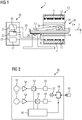
- Fig. 1 shows a schematic representation of an embodiment of a magnetic resonance tomograph 1 according to the invention.
- the magnet unit 10 has a field magnet 11 which generates a static magnetic field B0 for aligning nuclear spins of samples or patients 40 in a receiving area.
- the receiving region is arranged in a patient tunnel 16, which extends in a longitudinal direction 2 through the magnet unit 10 and is movable by the movement unit 36.
- the field magnet 11 is a superconducting magnet that can provide magnetic fields with a magnetic flux density of up to 3T, and even more, in the latest devices. For lower field strengths, however, it is also possible to use permanent magnets or electromagnets with normally conducting coils.
- the magnet unit 10 has gradient coils 12 which are designed to superpose variable magnetic fields in three spatial directions on the magnetic field B0 in order to spatially differentiate the detected imaging areas in the examination volume.
- the gradient coils 12 are usually coils of normal conducting wires which can generate mutually orthogonal fields in the examination volume.
- the magnet unit 10 likewise has a body coil 14, which is designed to radiate a high-frequency signal supplied via a signal line into the examination volume and to receive resonance signals emitted by the patient 40 and to output them via a signal line.
- the body coil 14 is for receiving the High frequency signal replaced by local coils 50, which are arranged in the patient tunnel 16 close to the patient 40.
- the local coil 50 is designed for transmission and reception.
- a control unit 20 supplies the magnet unit 10 with the various signals for the gradient coils 12 and the body coil 14 and evaluates the received signals.
- control unit 20 has a gradient control 21, which is designed to supply the gradient coils 12 via supply lines with variable currents, which provide time-coordinated the desired gradient fields in the examination volume.
- control unit 20 has a radio-frequency unit 22 which is designed to generate a radio-frequency pulse having a predetermined time profile, amplitude and spectral power distribution for exciting a magnetic resonance of the nuclear spins in the patient 40.
- pulse powers in the range of kilowatts can be achieved.
- the radio-frequency unit 22 has a frequency generator 35 which is designed to generate a first auxiliary frequency signal and a second auxiliary frequency signal for the local coil, as explained below, and to transmit them to the local coil 50 via the signal connection 33.
- Fig. 2 a local coil according to the invention is shown schematically in overview.
- the antenna coils 51 receive magnetic resonance signals from the body of the patient 40.
- the two antenna coils 51 cover different spatial regions.
- the weak magnetic resonance signals are first amplified by a low-noise preamplifier 52 (LNA). So that the signals can be evaluated separately, they become available for transmission by means of frequency division multiplexing a common line of a first mixer 53 and a second mixer 54 to different intermediate frequencies ZF1 and ZF2 implemented.
- the mixed frequency signals for the first mixer 53 and the second mixer 54 become as follows FIG. 3 and FIG. 4 explained by the local oscillator 60.
- a mixer 53, 54 for example, ring mixer, push-pull mixer or as a simple diode mixer are executed.
- An embodiment in digital signal processing, for example, as a multiplier or AND gate conceivable.
- the output signals of the first mixer 53 and the second mixer 54 are spectrally cleaned by means of a first filter 55 and a second filter 56, i. unwanted frequency components are compared to desired signals by 6 dB. 12 dB or more attenuated.
- the first filter 55 and the second filter 56 may be bandpass filters with the center frequencies ZF1 and ZF2, respectively.
- the first filter 55 and the second filter 56 can be designed, for example, as passive or active LC or RC filters, be implemented by other analog filter techniques such as quartz or surface acoustic wave filters or by digital signal processing.
- the filtered output signals of the first mixer 53 and the second mixer 54 are combined, for example, by a summing 57 in the form of two resistors and output via a second diplexer 58 to the common signal connection 33.
- a summing 57 in the form of two resistors and output via a second diplexer 58 to the common signal connection 33.
- bandpass or high and low pass filters may be used, but other technologies such as e.g. a gyrator for merging or separating the incoming and outgoing signals conceivable.
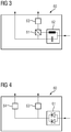
- Fig. 3 an exemplary embodiment of a local oscillator 60 is shown.
- the first auxiliary frequency signal and the second auxiliary frequency signal are supplied together via a first signal connection to the first diplexer 62, which separates the first auxiliary frequency signal from the second auxiliary frequency signal and provides a second signal connection and a third signal connection separately.
- the respective unwanted signal is attenuated by 6 dB, 12 dB 18 dB or more compared to the desired signal.
- the first mixing frequency signal supplied to the first mixer 53 is essentially identical to the first auxiliary frequency signal, ie the frequency position or the center frequency is the same and the levels are only slightly affected by the frequency response of the first diplexer 62 and the second one Diplexers 58 relative to the supplied via the signal input from the signal connection 33 changed.
- the second mixing frequency signal is generated by the auxiliary mixer 61 from the first auxiliary frequency signal and the second auxiliary frequency signal and the subsequent filter 63 by mixing.
- the first auxiliary mixer preferably has a design in which the originally supplied first auxiliary frequency signal and the second auxiliary frequency signal in the second mixed frequency signal is suppressed by 6 dB, 12 dB or more.
- the auxiliary mixer can be designed as a ring mixer or push-pull mixer. By suppressing the original auxiliary frequency signals in the auxiliary mixer, the filter 63 can be made simpler, for example as a simple low-pass filter.
- the frequencies of the auxiliary frequency signals 35 MHz and 50 MHz can be selected and the frequency of the first mixed frequency signal 35 MHz and the frequency of the second mixed frequency signal 15 MHz.
- Fig. 4 shows another possible embodiment of the local oscillator 60.
- the first auxiliary frequency signal and the second auxiliary frequency signal are supplied to the auxiliary mixer 61 via a common signal connection.
- auxiliary mixer 61 a non-linear element is conceivable in this embodiment, for example, one or two antiparallel connected diodes.
- Other non-linear amplifier elements such as transistors in the non-linear characteristic range are possible.
- Such non-linear mixers not only produce the second-order mixing signals at the signal output at a frequency corresponding to the sum or difference of the frequencies of the first auxiliary frequency signal and the second auxiliary frequency, but also result in higher-order mixing products.
- the first auxiliary frequency signal and the second auxiliary frequency signal at a comparable level.
- the local oscillator therefore also has filters 63, 64 with which the desired first mixed-frequency signal and the desired second mixed-frequency signal are filtered out of the output signal of the auxiliary mixer 61.
- filters 63, 64 with which the desired first mixed-frequency signal and the desired second mixed-frequency signal are filtered out of the output signal of the auxiliary mixer 61.
- the aforementioned analog or digital filter techniques can be used.
- the frequencies of the auxiliary frequency signals 35 MHz and 55 MHz can be selected and the frequency of the first mixed frequency signal 35 MHz and the frequency of the second mixed frequency signal 15 MHz.
Landscapes
- Physics & Mathematics (AREA)
- Condensed Matter Physics & Semiconductors (AREA)
- General Physics & Mathematics (AREA)
- Magnetic Resonance Imaging Apparatus (AREA)
Abstract
Description
- Die Erfindung betrifft eine Lokalspule sowie einen Magnetresonanztomographen mit einer Lokalspule. Die Lokalspule weist eine Vorrichtung zum Bereitstellen eines ersten Mischfrequenzsignals und eines zweiten Mischfrequenzsignals mittels eines ersten Hilfsfrequenzsignals und eines zweiten Hilfsfrequenzsignals auf.
- Magnetresonanztomographen sind bildgebende Vorrichtungen, die zur Abbildung eines Untersuchungsobjektes Kernspins des Untersuchungsobjektes mit einem starken äußeren Magnetfeld ausrichten und durch ein magnetisches Wechselfeld zur Präzession um diese Ausrichtung anregen. Die Präzession bzw. Rückkehr der Spins aus diesem angeregten in einen Zustand mit geringerer Energie wiederum erzeugt als Antwort ein magnetisches Wechselfeld, das über Antennen empfangen wird.
- Mit Hilfe von magnetischen Gradientenfeldern wird den Signalen eine Ortskodierung aufgeprägt, die nachfolgend eine Zuordnung von dem empfangenen Signal zu einem Volumenelement ermöglicht. Das empfangene Signal wird dann ausgewertet und eine dreidimensionale bildgebende Darstellung des Untersuchungsobjektes bereitgestellt. Zum Empfang des Signals werden vorzugsweise lokale Antennen, sogenannte Lokalspulen verwendet, die zur Erzielung eines besseren Signal-Rauschabstandes unmittelbar am Untersuchungsobjekt angeordnet werden.
- Um die Zahl der Kabelverbindungen zwischen Lokalspule und Magnetresonanztomograph zu verringern, können die Signale mehrerer Antennenspulen mittels Frequenzmultiplex gemeinsam übertragen werden. Dazu ist die Umsetzung auf unterschiedliche Trägerfrequenzen, auch als Zwischenfrequenz bezeichnet, durch Mischer erforderlich. Da für die Bildgebung mit Magnetresonanzsignalen Frequenz und Phase der Signale von großer Bedeutung sind, ist es dabei erforderlich, diese Größen auch bei der Übertragung mit Frequenzmultiplex zu erhalten. Es werden daher üblicherweise die die Hilfssignale zum Mischen zentral im Magnetresonanztomographen mit hoher Präzision erzeugt und dann an die Lokalspulen verteilt.
- Die Druckschrift
DE 10 2008 062 855 A1 beschreibt ein System, bei dem eine Vielzahl von Signalen von einer Basisstation zu einem Satelliten und in umgekehrter Richtung und durch jeweils eine Bandpassfilterbank spektral voneinander getrennt werden. - Aus der Druckschrift
DE 10 2009 008 623 A1 ist beispielsweise ein Magnetresonanztomograph bekannt, bei dem für ein Frequenzmultiplex Mischfrequenzsignale über separate Kabel zugeführt werden. - Bei Systemen mit niedrigeren Magnetfeldern sind die Larmorfrequenzen niedriger, sodass die Frequenzschemata der Hochfeldsysteme zur Vermeidung von Störungen durch die Zwischenfrequenzen nicht mehr anwendbar sind.
- Es ist daher eine Aufgabe der vorliegenden Erdfindung, eine Vorrichtung bereitzustellen, die eine flexiblere Frequenzwahl erlaubt.
- Die Aufgabe wird durch eine erfindungsgemäße Vorrichtung nach Anspruch 1 sowie einen Magnetresonanztomographen nach Anspruch 6 gelöst.
- Die erfindungsgemäße Lokalspule weist eine Vorrichtung zum Bereitstellen eines ersten Mischfrequenzsignals und eines zweiten Mischfrequenzsignals mittels eines ersten Hilfsfrequenzsignals und eines zweiten Hilfsfrequenzsignals auf. Das erste Hilfsfrequenzsignal und das zweite Hilfsfrequenzsignal weisen dabei unterschiedliche Frequenzen auf in dem Sinne, dass sich zumindest die Signalanteile mit den größten Amplituden in der Frequenz unterscheiden. Das erste Hilfsfrequenzsignal und das zweite Hilfsfrequenzsignal werden beispielsweise von einem Frequenzgenerator eines Magnetresonanztomographen bereitgestellt. Dabei ist höchstens die Frequenz des ersten Mischfrequenzsignals gleich einer Frequenz des ersten Hilfsfrequenzsignal oder des zweiten Hilfsfrequenzsignal. Mit anderen Worten, zumindest eine der beiden Mischfrequenzsignale wird nicht unmittelbar der Vorrichtung zugeführt, sondern durch ein Mischen aus dem ersten und dem zweiten Hilfsfrequenzsignal abgeleitet. Dabei wird unter Mischen eine Signalverarbeitung verstanden, die Intermodulationsprodukte des ersten und/oder zweiten Hilfsfrequenzsignals erzeugt. Dies kann analog durch nichtlineare Kennlinien, beispielsweise von Dioden oder Verstärkerelementen erreicht werden. In der digitalen Signalverarbeitung sind beispielsweise Multiplikation, Potenz- oder Exponentialfunktionen oder auch binäre Funktionen wie UND bzw. ODER-Funktion zur Erzeugung von Intermodulationsprodukten denkbar. Die Funktionseinheit, die das Mischen der ersten und der zweiten Hilfsfrequenz bzw. von daraus abgeleiteten Signalen ausführt, wird dabei im Folgenden als Hilfsmischer bezeichnet.
- Die erfindungsgemäße Vorrichtung weist einen derartigen Hilfsmischer auf, der ausgelegt ist, aus dem ersten Hilfsfrequenzsignal und dem zweiten Hilfsfrequenzsignal das zweite Mischfrequenzsignal zu erzeugen. Es ist darüber hinaus auch denkbar, dass das erste Mischfrequenzsignal ebenfalls durch den Hilfsmischer oder einen weiteren Hilfsmischer aus dem ersten Hilfsfrequenzsignal und dem zweiten Hilfsfrequenzsignal erzeugt wird, wobei die Frequenz des ersten Mischfrequenzsignals ungleich einer Frequenz des ersten Hilfsfrequenzsignals und des zweiten Hilfsfrequenzsignals und des zweiten Mischfrequenzsignals ist. Es ist aber ebenso denkbar, dass die Frequenz des ersten Mischfrequenzsignals gleich der Frequenz des ersten Hilfsfrequenzsignal oder des zweiten Hilfsfrequenzsignals ist.
- Die Lokalspule weist einen Signaleingang auf, der in einer ersten Signalverbindung mit der Vorrichtung steht. Die Lokalspule ist ausgelegt, das erste Hilfsfrequenzsignal und das zweite Hilfsfrequenzsignal gemeinsam über den Signaleingang zu empfangen und der Vorrichtung über die erste Signalverbindung zuzuführen.
- Auf vorteilhafte Weise ermöglicht es die erfindungsgemäße Vorrichtung, aus zwei Hilfsfrequenzsignalen, die über einen gemeinsamen Signaleingang zugeführt werden, zwei unterschiedliche Mischfrequenzen zu erzeugen und so die Wahl der Frequenzen der Hilfsfrequenzsignale von der Wahl der Frequenzen der Mischfrequenzsignale um mindestens einen Freiheitsgrad zu entkoppeln und flexibler zu gestalten.
- Der erfindungsgemäße Magnetresonanztomograph teilt die Vorteile der erfindungsgemäßen Lokalspule.
- Weitere vorteilhafte Ausführungsformen sind in den Unteransprüchen angegeben.
- In einer denkbaren Ausführungsform der erfindungsgemäßen Lokalspule weist die Vorrichtung einen ersten Diplexer auf. Der erste Diplexer steht über eine zweite Signalverbindung und eine dritte Signalverbindung mit dem Hilfsmischer in Signalverbindung.
- Der erste Diplexer ist ausgelegt, die über die erste Signalverbindung gemeinsam zugeführten erste Hilfsfrequenzsignal und zweite Hilfsfrequenzsignal zu trennen und getrennt über die zweite Signalverbindung und die dritte Signalverbindung dem Hilfsmischer zuzuführen. Beispielsweise kann durch einen Hochpass und/oder Tiefpass und/oder Bandpässe als Filter das erste Hilfsfrequenzsignal von dem zweiten Hilfsfrequenzsignal separiert werden und dann getrennt über die zweite Signalverbindung das erste Hilfsfrequenzsignal und die dritte Signalverbindung das zweite Hilfsfrequenzsignal dem Hilfsmischer zugeführt werden. Die Filter können beispielsweise durch passive LC-Kreise, aktive LC- oder RC-Filter oder in digitaler Signalverarbeitung durch entsprechende Schaltungen und/oder Algorithmen in einer Signalverarbeitungsressource wie einem Signalprozessor oder FPGA bereitgestellt sein.
- Die Trennung des ersten Hilfsfrequenzsignals von dem zweiten Hilfsfrequenzsignals erlaubt es in dem nachfolgenden Hilfsmischer vorteilhafte Schaltungstechniken zu verwenden. Beispielsweise können in einem Ringmischer das ursprüngliche erste Hilfsfrequenzsignal und das zweite Hilfsfrequenzsignal gegenüber dem ersten Mischfrequenzsignal und dem zweiten Mischfrequenzsignal unterdrückt werden.
- In einer denkbaren Ausführungsform der erfindungsgemäßen Vorrichtung ist der Hilfsmischer ausgelegt, das zweite Mischfrequenzsignal durch Intermodulation dritter Ordnung zu erzeugen.
- Eine Intermodulation dritter Ordnung lässt sich auf vorteilhafte Weise durch einen einfachen Diodenverzerrer, d.h. eine einzelne Diode oder ein antiparalleles Paar von Dioden bereitstellen, der am Signalausgang auch die ursprünglichen Hilfsfrequenzsignale für eine weitere Verwendung ausgibt.
- In einer möglichen Ausführungsform der erfindungsgemäßen Lokalspule weist die Vorrichtung ein Bandpassfilter auf, das eine vierte Signalverbindung zu einem ersten Signalausgang des Hilfsmischers aufweist. Das Bandpassfilter ist ausgelegt, das zweite Mischfrequenzsignal aus einem Ausgangssignal des Hilfsmischers zu filtern. Beispielsweise kann das Ausgangssignal des Hilfsmischers noch Anteile des ersten Hilfsfrequenzsignals und/oder des zweiten Hilfsfrequenzsignals oder Mischprodukte höherer Ordnung aufweisen, die durch das Bandpassfilter entfernt werden.
- Das Bandpassfilter ermöglicht auf vorteilhafte Weise die Verwendung eines einfachen Frequenzschemas und/oder Hilfsmischers, da unerwünschte Frequenzen durch das Bandpassfilter nachträglich ausgefiltert werden.
- In einer denkbaren Ausführungsform der erfindungsgemäßen Lokalspule weist der Hilfsmischer einen Diodenverzerrer auf.
- Ein Diodenverzerrer ist eine besonders einfache und kostengünstige Möglichkeit zur Erzeugung von Intermodulationsprodukten höherer Ordnung.
- In einer möglichen Ausführungsform des erfindungsgemäßen Magnetresonanztomographen weist der Magnetresonanztomograph einen Empfänger mit einem Signaleingang auf. Der Empfänger ist dabei ausgelegt, Empfangssignale mit einer Frequenz eines Mischsignals aus einem Magnetresonanzsignal mit Larmorfrequenz und erstem Mischfrequenzsignal und/oder zweitem Mischfrequenzsignal am Signaleingang zu empfangen und auszuwerten.
- Auf vorteilhafte Weise ist der Magnetresonanztomograph in der Lage, die mittels der Hilfsfrequenzen erzeugten und im Frequenzmultiplex über eine gemeinsame Leitung übertragenen Magnetresonanzsignale auszuwerten.
- Die oben beschriebenen Eigenschaften, Merkmale und Vorteile dieser Erfindung sowie die Art und Weise, wie diese erreicht werden, werden klarer und deutlicher verständlich im Zusammenhang mit der folgenden Beschreibung der Ausführungsbeispiele, die im Zusammenhang mit den Zeichnungen näher erläutert werden.
- Es zeigen:
- Fig. 1
- eine schematische Darstellung eines erfindungsgemäßen Magnetresonanztomographen mit einer beispielhaften erfindungsgemäßen Lokalspule;
- Fig. 2
- eine schematische Darstellung einer Ausführungsform einer erfindungsgemäßen Lokalspule;
- Fig. 3
- eine schematische Darstellung eines Lokaloszillators einer Ausführungsform einer erfindungsgemäßen Lokalspule;
- Fig. 4
- eine schematische Darstellung eines Lokaloszillators einer Ausführungsform einer erfindungsgemäßen Lokalspule;
-
Fig. 1 zeigt eine schematische Darstellung einer Ausführungsform eines erfindungsgemäßen Magnetresonanztomographen 1. - Die Magneteinheit 10 weist einen Feldmagneten 11 auf, der ein statisches Magnetfeld B0 zur Ausrichtung von Kernspins von Proben bzw. Patienten 40 in einem Aufnahmebereich erzeugt. Der Aufnahmebereich ist in einem Patiententunnel 16 angeordnet, der sich in einer Längsrichtung 2 durch die Magneteinheit 10 erstreckt und von der Verfahreinheit 36 bewegbar ist. Üblicherweise handelt es sich bei dem Feldmagneten 11 um einen supraleitenden Magneten, der magnetische Felder mit einer magnetischen Flussdichte von bis zu 3T, bei neuesten Geräten sogar darüber, bereitstellen kann. Für geringere Feldstärken können jedoch auch Permanentmagnete oder Elektromagnete mit normalleitenden Spulen Verwendung finden.
- Weiterhin weist die Magneteinheit 10 Gradientenspulen 12 auf, die dazu ausgelegt sind, zur räumlichen Differenzierung der erfassten Abbildungsbereiche in dem Untersuchungsvolumen dem Magnetfeld B0 variable Magnetfelder in drei Raumrichtungen zu überlagern. Die Gradientenspulen 12 sind üblicherweise Spulen aus normalleitenden Drähten, die zueinander orthogonale Felder in dem Untersuchungsvolumen erzeugen können.
- Die Magneteinheit 10 weist ebenfalls eine Körperspule 14 auf, die dazu ausgelegt ist, ein über eine Signalleitung zugeführtes Hochfrequenzsignal in das Untersuchungsvolumen abzustrahlen und von dem Patient 40 emittierte Resonanzsignale zu empfangen und über eine Signalleitung abzugeben. Bevorzugter Weise wird aber die Körperspule 14 für das Empfangen des Hochfrequenzsignals durch Lokalspulen 50 ersetzt, die in dem Patiententunnel 16 nahe am Patient 40 angeordnet sind. Es ist aber auch denkbar, dass die Lokalspule 50 zum Senden und Empfangen ausgelegt ist.
- Eine Steuereinheit 20 versorgt die Magneteinheit 10 mit den verschiedenen Signalen für die Gradientenspulen 12 und die Körperspule 14 und wertet die empfangenen Signale aus.
- So weist die Steuereinheit 20 eine Gradientenansteuerung 21 auf, die dazu ausgelegt ist, die Gradientenspulen 12 über Zuleitungen mit variablen Strömen zu versorgen, welche zeitlich koordiniert die erwünschten Gradientenfelder in dem Untersuchungsvolumen bereitstellen.
- Weiterhin weist die Steuereinheit 20 eine Hochfrequenzeinheit 22 auf, die ausgelegt ist, einen Hochfrequenz-Puls mit einem vorgegebenen zeitlichen Verlauf, Amplitude und spektraler Leistungsverteilung zur Anregung einer Magnetresonanz der Kernspins in dem Patienten 40 zu erzeugen. Dabei können Pulsleistungen im Bereich von Kilowatt erreicht werden.
- Weiterhin weist die Hochfrequenzeinheit 22 einen Frequenzgenerator 35 auf, der ausgelegt ist, für die Lokalspule, wie nachfolgend erläutert, ein erstes Hilfsfrequenzsignal und ein zweites Hilfsfrequenzsignal zu erzeugen und über die Signalverbindung 33 zu der Lokalspule 50 zu übertragen.
- In
Fig. 2 ist eine erfindungsgemäße Lokalspule schematisch im Überblick dargestellt. - Die Antennenspulen 51 empfangen Magnetresonanzsignale aus dem Körper des Patienten 40. Vorzugsweise decken die beiden Antennenspulen 51 dabei unterschiedliche räumliche Bereiche ab. Die schwachen Magnetresonanzsignale werden zunächst von einem rauscharmen Vorverstärker 52 (Low Noise Amplifier, LNA) verstärkt. Damit die Signale separat ausgewertet werden können, werden sie für eine Übertragung mittels Frequenzmultiplex auf einer gemeinsamen Leitung von einem ersten Mischer 53 und einem zweiten Mischer 54 auf unterschiedliche Zwischenfrequenzen ZF1 und ZF2 umgesetzt. Die Mischfrequenzsignale für den ersten Mischer 53 und den zweiten Mischer 54 werden wie nachfolgend zu
Fig. 3 und Fig. 4 erläutert von dem Lokaloszillator 60 bereitgestellt. Als Mischer 53, 54 sind beispielsweise Ringmischer, Gegentaktmischer oder als einfacher Diodenmischer ausgeführt. Auch eine Ausführung in der digitalen Signalverarbeitung, z.B. als Multiplikator oder Und-Gatter denkbar. - Um unerwünschte Mischprodukte zu unterdrücken, werden vorzugsweise die Ausgangssignale des ersten Mischers 53 und des zweiten Mischers 54 mittels eines ersten Filters 55 und eines zweiten Filters 56 spektral gesäubert, d.h. unerwünschte Frequenzanteile werden gegenüber erwünschten Signalen um 6 dB. 12 dB oder mehr gedämpft. Es kann sich bei dem ersten Filter 55 und dem zweiten Filter 56 beispielsweise um Bandpässe jeweils mit der Mittenfrequenz ZF1 bzw. ZF2 handeln. Der erste Filter 55 und der zweite Filter 56 können beispielsweise als passive oder aktive LC- bzw. RC-Filter ausgeführt sein, durch andere analoge Filtertechniken wie Quarz- oder Oberflächenwellenfilter oder auch durch digitale Signalverarbeitung realisiert sein.
- Die gefilterten Ausgangssignale des ersten Mischers 53 und des zweiten Mischers 54 werden zusammengeführt, beispielsweise durch ein Summierglied 57 in Form von zwei Widerständen und über einen zweiten Diplexer 58 auf die gemeinsame Signalverbindung 33 ausgegeben. Als zweiter Diplexer 58 können bei unterschiedlichen Frequenzbereichen für die Hilfsfrequenzsignale und die Zwischenfrequenzsignale Bandpass- oder Hoch- und Tiefpass-Filter dienen, es sind aber auch andere Technologien wie z.B. ein Gyrator zum Zusammenführen bzw. Trennen der ein- und ausgehenden Signale denkbar.
- In
Fig. 3 ist eine beispielhafte Ausführungsform eines Lokaloszillators 60 dargestellt. In der Ausführungsform derFig. 3 werden das erste Hilfsfrequenzsignal und das zweite Hilfsfrequenzsignal gemeinsam über eine erste Signalverbindung dem ersten Diplexer 62 zugeführt, der das erste Hilfsfrequenzsignal von dem zweiten Hilfsfrequenzsignal trennt und einer zweiten Signalverbindung und einer dritten Signalverbindung getrennt bereitstellt. Als Trennen ist dabei zu verstehen, dass das jeweils unerwünschte Signal um 6 dB, 12 dB 18 dB oder mehr gegenüber dem erwünschten Signal gedämpft ist. - In der in
Fig. 3 dargestellten Ausführungsform ist dabei das erste Mischfrequenzsignal, das dem ersten Mischer 53 zugeführt wird, im Wesentlichen identisch mit dem ersten Hilfsfrequenzsignal, d.h. die Frequenzlage bzw. die Mittenfrequenz ist die gleiche und die Pegel sind nur geringfügig durch den Frequenzgang des ersten Diplexers 62 und des zweiten Diplexers 58 gegenüber dem über den Signaleingang von der Signalverbindung 33 zugeführten verändert. - Das zweite Mischfrequenzsignal wird durch den Hilfsmischer 61 aus dem ersten Hilfsfrequenzsignal und dem zweite Hilfsfrequenzsignal und das nachfolgende Filter 63 durch Mischung erzeugt. Dabei ist weist der erste Hilfsmischer vorzugsweise eine Bauform auf, bei der das ursprünglich zugeführte erste Hilfsfrequenzsignal und das zweite Hilfsfrequenzsignal im zweiten Mischfrequenzsignal um 6 dB, 12 dB oder mehr unterdrückt ist. Beispielsweise kann der Hilfsmischer als Ringmischer oder Gegentaktmischer ausgeführt sein. Durch die Unterdrückung der ursprünglichen Hilfsfrequenzsignale im Hilfsmischer kann der Filter 63 einfacher ausgeführt sein, beispielsweise als einfacher Tiefpass.
- In einer Ausführungsform der
Fig. 3 können beispielsweise als Frequenzen der Hilfsfrequenzsignale 35 MHz und 50 MHz gewählt werden und als Frequenz des ersten Mischfrequenzsignals 35 MHz und als Frequenz des zweiten Mischfrequenzsignals 15 MHz. -
Fig. 4 zeigt eine andere mögliche Ausführungsform des Lokaloszillators 60. Bei dieser Ausführungsform ist kein erster Diplexer 62 erforderlich, sondern das erste Hilfsfrequenzsignal und das zweite Hilfsfrequenzsignal werden dem Hilfsmischer 61 über eine gemeinsame Signalverbindung zugeführt. Als Hilfsmischer 61 ist in dieser Ausführungsform ein nichtlineares Element denkbar, beispielsweise eine oder auch zwei antiparallel geschaltete Dioden. Auch andere nichtlineare Verstärkerelemente wie Transistoren im nichtlinearen Kennlinienbereich sind möglich. Derartige nichtlineare Mischer erzeugen am Signalausgang nicht nur die Mischsignale zweiter Ordnung mit einer Frequenz, die jeweils der Summe bzw. der Differenz der Frequenzen des ersten Hilfsfrequenzsignals und des zweiten Hilfsfrequenz entsprechen, sondern es entstehen auch Mischprodukte höherer Ordnung. Darüber hinaus liegen am Signalausgang des Hilfsmischers 61 in einer derartigen Ausführungsform auch das erste Hilfsfrequenzsignal und das zweite Hilfsfrequenzsignal mit vergleichbarem Pegel an. - In der Ausführungsform de
Fig. 4 weist der Lokaloszillator deshalb auch Filter 63, 64 auf, mit denen aus dem Ausgangssignal des Hilfsmischers 61 das gewünschte erste Mischfrequenzsignal und das gewünschte zweite Mischfrequenzsignal herausgefiltert werden. Als Filter können dabei die zuvor genannten analogen oder digitalen Filtertechniken Anwendung finden. - Die zusätzlich erzeugten Mischprodukte höherer Ordnung erfordern dabei zwar den größeren Aufwand in der Filterung, erlauben aber die Verwendung preisgünstiger Mischertechniken und geben durch die zusätzlichen Mischprodukte zusätzliche Freiheitsgrade bei der Wahl der der Frequenzen der Hilfsfrequenzsignale, der Mischfrequenzsignale und der Zwischenfrequenzen.
- In einer Ausführungsform der
Fig. 4 können beispielsweise als Frequenzen der Hilfsfrequenzsignale 35 MHz und 55 MHz gewählt werden und als Frequenz des ersten Mischfrequenzsignals 35 MHz und als Frequenz des zweiten Mischfrequenzsignals 15 MHz. - Obwohl die Erfindung im Detail durch das bevorzugte Ausführungsbeispiel näher illustriert und beschrieben wurde, so ist die Erfindung nicht durch die offenbarten Beispiele eingeschränkt und andere Variationen können vom Fachmann hieraus abgeleitet werden, ohne den Schutzumfang der Erfindung zu verlassen.
Claims (7)
- Lokalspule mit Vorrichtung zum Bereitstellen eines ersten Mischfrequenzsignals und eines zweiten Mischfrequenzsignals mittels eines ersten Hilfsfrequenzsignals und eines zweiten Hilfsfrequenzsignals,
wobei höchstens die Frequenz des ersten Mischfrequenzsignals gleich einer Frequenz eines von dem ersten Hilfsfrequenzsignal oder dem zweiten Hilfsfrequenzsignal ist,
wobei die Vorrichtung einen Hilfsmischer (61) aufweist, der ausgelegt ist, aus dem ersten Hilfsfrequenzsignal und dem zweiten Hilfsfrequenzsignal das zweite Mischfrequenzsignal zu erzeugen,
wobei die Lokalspule (50) einen Signaleingang aufweist, der in einer ersten Signalverbindung mit der Vorrichtung steht und die Lokalspule (50) ausgelegt ist, das erste Hilfsfrequenzsignal und das zweite Hilfsfrequenzsignal gemeinsam über den Signaleingang zu empfangen und der Vorrichtung über die erste Signalverbindung zuzuführen. - Lokalspule nach Anspruch 1, wobei die Vorrichtung einen ersten Diplexer (62) aufweist und eine zweite Signalverbindung und eine dritte Signalverbindung zwischen dem ersten Diplexer (62) und dem Hilfsmischer (61) aufweist,
wobei der erste Diplexer (62) ausgelegt ist, die über die erste Signalverbindung gemeinsam zugeführten erste Hilfsfrequenzsignal und zweite Hilfsfrequenzsignal zu trennen und getrennt über die zweite Signalverbindung und die dritte Signalverbindung dem Hilfsmischer (61) zuzuführen. - Lokalspule nach Anspruch 1, wobei der Hilfsmischer (61) ausgelegt ist, das zweite Mischfrequenzsignal durch Intermodulation dritter Ordnung zu erzeugen.
- Lokalspule nach Anspruch 3, wobei die Vorrichtung ein Bandpassfilter aufweist, das eine vierte Signalverbindung zu einem ersten Signalausgang des Hilfsmischers aufweist und ausgelegt ist, das zweite Mischfrequenzsignal aus einem Ausgangssignal des Hilfsmischers zu filtern.
- Lokalspule nach Anspruch 3, wobei der Hilfsmischer (61) einen Diodenverzerrer aufweist.
- Magnetresonanztomograph mit einer Lokalspule (50) nach einem der vorhergehenden Ansprüche, wobei der Magnetresonanztomograph (1) einen Frequenzgenerator (35) aufweist und ausgelegt ist, das erste Hilfsfrequenzsignal und das zweite Hilfsfrequenzsignal an einem zweiten Signalausgang bereitzustellen.
- Magnetresonanztomograph nach Anspruch 6, wobei der Magnetresonanztomograph (1) einen Empfänger mit einem Signaleingang aufweist, wobei der Empfänger ausgelegt ist, Empfangssignale mit einer Frequenz eines Mischsignals aus einem Magnetresonanzsignal mit Larmorfrequenz und erstem Mischfrequenzsignal und/oder zweitem Mischfrequenzsignal am Signaleingang zu empfangen und auszuwerten.
Priority Applications (3)
| Application Number | Priority Date | Filing Date | Title |
|---|---|---|---|
| EP17176022.6A EP3309573B1 (de) | 2017-06-14 | 2017-06-14 | Lokal lo generator für mrt lokalspulen mit frequenzumsetzer |
| US15/997,109 US10605876B2 (en) | 2017-06-14 | 2018-06-04 | Local coil with frequency converter |
| CN201810605832.4A CN109085518B (zh) | 2017-06-14 | 2018-06-13 | 具有频率转换器的局部线圈 |
Applications Claiming Priority (1)
| Application Number | Priority Date | Filing Date | Title |
|---|---|---|---|
| EP17176022.6A EP3309573B1 (de) | 2017-06-14 | 2017-06-14 | Lokal lo generator für mrt lokalspulen mit frequenzumsetzer |
Publications (2)
| Publication Number | Publication Date |
|---|---|
| EP3309573A1 true EP3309573A1 (de) | 2018-04-18 |
| EP3309573B1 EP3309573B1 (de) | 2019-07-24 |
Family
ID=59061918
Family Applications (1)
| Application Number | Title | Priority Date | Filing Date |
|---|---|---|---|
| EP17176022.6A Active EP3309573B1 (de) | 2017-06-14 | 2017-06-14 | Lokal lo generator für mrt lokalspulen mit frequenzumsetzer |
Country Status (3)
| Country | Link |
|---|---|
| US (1) | US10605876B2 (de) |
| EP (1) | EP3309573B1 (de) |
| CN (1) | CN109085518B (de) |
Families Citing this family (1)
| Publication number | Priority date | Publication date | Assignee | Title |
|---|---|---|---|---|
| DE102019205114B4 (de) * | 2019-04-10 | 2022-02-10 | Siemens Healthcare Gmbh | Einstufiger Verstärker mit aktiver Rückwirkungskompensation |
Citations (4)
| Publication number | Priority date | Publication date | Assignee | Title |
|---|---|---|---|---|
| US20080003968A1 (en) * | 2006-06-30 | 2008-01-03 | Qiang Li | LO generator to reject unwanted sideband |
| DE102008062855A1 (de) | 2008-12-23 | 2010-07-08 | Siemens Aktiengesellschaft | Ferngespeistes Modul |
| DE102009008623B3 (de) | 2009-02-12 | 2010-12-30 | Siemens Aktiengesellschaft | Verfahren und Anordnung zur Übertragung von Magnetresonanzsignalen |
| DE102010027672A1 (de) * | 2010-07-20 | 2012-01-26 | Siemens Aktiengesellschaft | Vorverarbeitungseinrichtung für Empfangssignale einer Lokalspule, Lokalspule und Verfahren zur Bereitstellung wenigstens eines Hilfsfrequenzsignals |
Family Cites Families (5)
| Publication number | Priority date | Publication date | Assignee | Title |
|---|---|---|---|---|
| DE102008023467B4 (de) * | 2008-05-14 | 2012-06-14 | Siemens Aktiengesellschaft | Anordnung zur Übertragung von Magnetresonanzsignalen |
| DE102009052197B4 (de) * | 2009-11-06 | 2013-06-13 | Siemens Aktiengesellschaft | MR-Signal-Übertragung in einer Lokalspulenanordnung |
| DE102012205333B4 (de) * | 2012-04-02 | 2015-05-28 | Siemens Aktiengesellschaft | Magnetresonanztomograph |
| US10511261B2 (en) * | 2016-04-08 | 2019-12-17 | Case Western Reserve University | System and method for improved RF system performance in MRI systems |
| CN106771686A (zh) * | 2016-11-15 | 2017-05-31 | 中国电子科技集团公司第四十研究所 | 一种噪声系数分析仪扩频模块的本振发生装置及方法 |
-
2017
- 2017-06-14 EP EP17176022.6A patent/EP3309573B1/de active Active
-
2018
- 2018-06-04 US US15/997,109 patent/US10605876B2/en active Active
- 2018-06-13 CN CN201810605832.4A patent/CN109085518B/zh active Active
Patent Citations (4)
| Publication number | Priority date | Publication date | Assignee | Title |
|---|---|---|---|---|
| US20080003968A1 (en) * | 2006-06-30 | 2008-01-03 | Qiang Li | LO generator to reject unwanted sideband |
| DE102008062855A1 (de) | 2008-12-23 | 2010-07-08 | Siemens Aktiengesellschaft | Ferngespeistes Modul |
| DE102009008623B3 (de) | 2009-02-12 | 2010-12-30 | Siemens Aktiengesellschaft | Verfahren und Anordnung zur Übertragung von Magnetresonanzsignalen |
| DE102010027672A1 (de) * | 2010-07-20 | 2012-01-26 | Siemens Aktiengesellschaft | Vorverarbeitungseinrichtung für Empfangssignale einer Lokalspule, Lokalspule und Verfahren zur Bereitstellung wenigstens eines Hilfsfrequenzsignals |
Also Published As
| Publication number | Publication date |
|---|---|
| US10605876B2 (en) | 2020-03-31 |
| US20180364320A1 (en) | 2018-12-20 |
| EP3309573B1 (de) | 2019-07-24 |
| CN109085518B (zh) | 2021-07-23 |
| CN109085518A (zh) | 2018-12-25 |
Similar Documents
| Publication | Publication Date | Title |
|---|---|---|
| DE102014206311B3 (de) | Empfangssystem für Lokalspulen eines Magnetresonanztomographiesystems | |
| DE60026795T2 (de) | Gerät magnetischer Resonanz | |
| DE60035829T2 (de) | RF-Körperspule für ein offenes System zur Bilderzeugung mittels magnetischer Resonanz | |
| EP3467531A1 (de) | Magnetresonanztomograph mit aktiver störunterdrückung und verfahren zur störunterdrückung in einem magnetresonanztomographen | |
| DE102011086288B4 (de) | Magnetresonanztomographie-System, Empfangsvorrichtung für ein solches System sowie Verfahren zum Gewinnen eines Bildsignals in dem System | |
| DE102008033708A1 (de) | HF-Spulenbaueinheit für Magnetresonanzbildgebungssystem | |
| DE4037294A1 (de) | Empfaengerschaltanordnung mit einer gruppe von oberflaechenspulen | |
| DE112011104494T5 (de) | Verfahren zur Reduzierung der deponierten Leistung bei Magnetresonanz- Tomografie unter Verwendung von Vielband-Pulsen und Vielkanal-Übertragung | |
| DE102010027672B4 (de) | Vorverarbeitungseinrichtung für Empfangssignale einer Lokalspule, Lokalspule und Verfahren zur Bereitstellung wenigstens eines Hilfsfrequenzsignals | |
| EP3242396A1 (de) | Vorrichtung zur übertragung von magnetresonanzsignalen mittels differentieller leitungsführung | |
| DE102013205464A1 (de) | Lokalspulensystem zum Erfassen von Magnetresonanz-Signalen mit einer Energieempfangsantenne zum induktiven Empfangen von Energie für das Lokalspulensystem | |
| EP3309573B1 (de) | Lokal lo generator für mrt lokalspulen mit frequenzumsetzer | |
| DE102008062855B4 (de) | Verfahren und Vorrichtung zur Übertragung von Signalen | |
| DE3739856A1 (de) | Kernresonanz-spektroskopieverfahren | |
| EP0329240A2 (de) | Verfahren zur Ermittlung der spektralen Verteilung der Kernmagnetisierung in einem begrenzten Volumenbereich und Anordnung zur Durchführung des Verfahrens | |
| EP3270177A1 (de) | Verfahren zum betreiben einer lokalspule und lokalspule sowie magnetresonanztomograph | |
| DE102015218331A1 (de) | Verfahren und Vorrichtung zur Signalübertragung in Magnetresonanztomographen | |
| DE102007001299A1 (de) | Anordnung zur Signalumwandlung | |
| DE202017004947U1 (de) | Skalierbare Breitbandschaltmatrix für Magnetresonanztomograph und Magnetresonanztomograph und Lokalspule dafür | |
| EP3134745B1 (de) | Vorrichtung und verfahren zur elektrischen anbindung von elektronischen baugruppen mittels symmetrischer abgeschirmter leitung | |
| DE3724606A1 (de) | Spulenanordnung fuer magnetresonanzabbildung | |
| EP3252490B1 (de) | Vorrichtung und verfahren zur übertragung von radiofrequenz-signalen über eine geschirmte, symmetrische leitung | |
| DE3906978A1 (de) | Verfahren zur lokalisierten kernresonanzspektroskopie und anordnung zur durchfuehrung des verfahrens | |
| DE202018005094U1 (de) | Symmetrierglied mit integrierter Impedanzwandlung und Bandpassfilter | |
| DE10221850B4 (de) | Verfahren zum Gestalten eines selektiven HF-Pulses und selektiver HF-Puls |
Legal Events
| Date | Code | Title | Description |
|---|---|---|---|
| PUAI | Public reference made under article 153(3) epc to a published international application that has entered the european phase |
Free format text: ORIGINAL CODE: 0009012 |
|
| STAA | Information on the status of an ep patent application or granted ep patent |
Free format text: STATUS: THE APPLICATION HAS BEEN PUBLISHED |
|
| STAA | Information on the status of an ep patent application or granted ep patent |
Free format text: STATUS: REQUEST FOR EXAMINATION WAS MADE |
|
| AK | Designated contracting states |
Kind code of ref document: A1 Designated state(s): AL AT BE BG CH CY CZ DE DK EE ES FI FR GB GR HR HU IE IS IT LI LT LU LV MC MK MT NL NO PL PT RO RS SE SI SK SM TR |
|
| AX | Request for extension of the european patent |
Extension state: BA ME |
|
| 17P | Request for examination filed |
Effective date: 20180319 |
|
| RBV | Designated contracting states (corrected) |
Designated state(s): AL AT BE BG CH CY CZ DE DK EE ES FI FR GB GR HR HU IE IS IT LI LT LU LV MC MK MT NL NO PL PT RO RS SE SI SK SM TR |
|
| STAA | Information on the status of an ep patent application or granted ep patent |
Free format text: STATUS: EXAMINATION IS IN PROGRESS |
|
| 17Q | First examination report despatched |
Effective date: 20180614 |
|
| REG | Reference to a national code |
Ref country code: DE Ref legal event code: R079 Ref document number: 502017001827 Country of ref document: DE Free format text: PREVIOUS MAIN CLASS: G01R0033360000 Ipc: H03B0021010000 |
|
| RIC1 | Information provided on ipc code assigned before grant |
Ipc: G01R 33/341 20060101ALN20181217BHEP Ipc: G01R 33/36 20060101ALI20181217BHEP Ipc: H03B 21/01 20060101AFI20181217BHEP |
|
| GRAP | Despatch of communication of intention to grant a patent |
Free format text: ORIGINAL CODE: EPIDOSNIGR1 |
|
| STAA | Information on the status of an ep patent application or granted ep patent |
Free format text: STATUS: GRANT OF PATENT IS INTENDED |
|
| INTG | Intention to grant announced |
Effective date: 20190201 |
|
| GRAS | Grant fee paid |
Free format text: ORIGINAL CODE: EPIDOSNIGR3 |
|
| GRAA | (expected) grant |
Free format text: ORIGINAL CODE: 0009210 |
|
| STAA | Information on the status of an ep patent application or granted ep patent |
Free format text: STATUS: THE PATENT HAS BEEN GRANTED |
|
| AK | Designated contracting states |
Kind code of ref document: B1 Designated state(s): AL AT BE BG CH CY CZ DE DK EE ES FI FR GB GR HR HU IE IS IT LI LT LU LV MC MK MT NL NO PL PT RO RS SE SI SK SM TR |
|
| REG | Reference to a national code |
Ref country code: GB Ref legal event code: FG4D Free format text: NOT ENGLISH |
|
| REG | Reference to a national code |
Ref country code: CH Ref legal event code: EP |
|
| REG | Reference to a national code |
Ref country code: DE Ref legal event code: R096 Ref document number: 502017001827 Country of ref document: DE |
|
| REG | Reference to a national code |
Ref country code: AT Ref legal event code: REF Ref document number: 1159412 Country of ref document: AT Kind code of ref document: T Effective date: 20190815 |
|
| REG | Reference to a national code |
Ref country code: IE Ref legal event code: FG4D Free format text: LANGUAGE OF EP DOCUMENT: GERMAN |
|
| REG | Reference to a national code |
Ref country code: NL Ref legal event code: MP Effective date: 20190724 |
|
| REG | Reference to a national code |
Ref country code: LT Ref legal event code: MG4D |
|
| PG25 | Lapsed in a contracting state [announced via postgrant information from national office to epo] |
Ref country code: LT Free format text: LAPSE BECAUSE OF FAILURE TO SUBMIT A TRANSLATION OF THE DESCRIPTION OR TO PAY THE FEE WITHIN THE PRESCRIBED TIME-LIMIT Effective date: 20190724 Ref country code: FI Free format text: LAPSE BECAUSE OF FAILURE TO SUBMIT A TRANSLATION OF THE DESCRIPTION OR TO PAY THE FEE WITHIN THE PRESCRIBED TIME-LIMIT Effective date: 20190724 Ref country code: PT Free format text: LAPSE BECAUSE OF FAILURE TO SUBMIT A TRANSLATION OF THE DESCRIPTION OR TO PAY THE FEE WITHIN THE PRESCRIBED TIME-LIMIT Effective date: 20191125 Ref country code: SE Free format text: LAPSE BECAUSE OF FAILURE TO SUBMIT A TRANSLATION OF THE DESCRIPTION OR TO PAY THE FEE WITHIN THE PRESCRIBED TIME-LIMIT Effective date: 20190724 Ref country code: NO Free format text: LAPSE BECAUSE OF FAILURE TO SUBMIT A TRANSLATION OF THE DESCRIPTION OR TO PAY THE FEE WITHIN THE PRESCRIBED TIME-LIMIT Effective date: 20191024 Ref country code: BG Free format text: LAPSE BECAUSE OF FAILURE TO SUBMIT A TRANSLATION OF THE DESCRIPTION OR TO PAY THE FEE WITHIN THE PRESCRIBED TIME-LIMIT Effective date: 20191024 Ref country code: NL Free format text: LAPSE BECAUSE OF FAILURE TO SUBMIT A TRANSLATION OF THE DESCRIPTION OR TO PAY THE FEE WITHIN THE PRESCRIBED TIME-LIMIT Effective date: 20190724 Ref country code: HR Free format text: LAPSE BECAUSE OF FAILURE TO SUBMIT A TRANSLATION OF THE DESCRIPTION OR TO PAY THE FEE WITHIN THE PRESCRIBED TIME-LIMIT Effective date: 20190724 |
|
| PG25 | Lapsed in a contracting state [announced via postgrant information from national office to epo] |
Ref country code: RS Free format text: LAPSE BECAUSE OF FAILURE TO SUBMIT A TRANSLATION OF THE DESCRIPTION OR TO PAY THE FEE WITHIN THE PRESCRIBED TIME-LIMIT Effective date: 20190724 Ref country code: IS Free format text: LAPSE BECAUSE OF FAILURE TO SUBMIT A TRANSLATION OF THE DESCRIPTION OR TO PAY THE FEE WITHIN THE PRESCRIBED TIME-LIMIT Effective date: 20191124 Ref country code: LV Free format text: LAPSE BECAUSE OF FAILURE TO SUBMIT A TRANSLATION OF THE DESCRIPTION OR TO PAY THE FEE WITHIN THE PRESCRIBED TIME-LIMIT Effective date: 20190724 Ref country code: GR Free format text: LAPSE BECAUSE OF FAILURE TO SUBMIT A TRANSLATION OF THE DESCRIPTION OR TO PAY THE FEE WITHIN THE PRESCRIBED TIME-LIMIT Effective date: 20191025 Ref country code: AL Free format text: LAPSE BECAUSE OF FAILURE TO SUBMIT A TRANSLATION OF THE DESCRIPTION OR TO PAY THE FEE WITHIN THE PRESCRIBED TIME-LIMIT Effective date: 20190724 Ref country code: ES Free format text: LAPSE BECAUSE OF FAILURE TO SUBMIT A TRANSLATION OF THE DESCRIPTION OR TO PAY THE FEE WITHIN THE PRESCRIBED TIME-LIMIT Effective date: 20190724 |
|
| PG25 | Lapsed in a contracting state [announced via postgrant information from national office to epo] |
Ref country code: TR Free format text: LAPSE BECAUSE OF FAILURE TO SUBMIT A TRANSLATION OF THE DESCRIPTION OR TO PAY THE FEE WITHIN THE PRESCRIBED TIME-LIMIT Effective date: 20190724 |
|
| PG25 | Lapsed in a contracting state [announced via postgrant information from national office to epo] |
Ref country code: PL Free format text: LAPSE BECAUSE OF FAILURE TO SUBMIT A TRANSLATION OF THE DESCRIPTION OR TO PAY THE FEE WITHIN THE PRESCRIBED TIME-LIMIT Effective date: 20190724 Ref country code: DK Free format text: LAPSE BECAUSE OF FAILURE TO SUBMIT A TRANSLATION OF THE DESCRIPTION OR TO PAY THE FEE WITHIN THE PRESCRIBED TIME-LIMIT Effective date: 20190724 Ref country code: IT Free format text: LAPSE BECAUSE OF FAILURE TO SUBMIT A TRANSLATION OF THE DESCRIPTION OR TO PAY THE FEE WITHIN THE PRESCRIBED TIME-LIMIT Effective date: 20190724 Ref country code: RO Free format text: LAPSE BECAUSE OF FAILURE TO SUBMIT A TRANSLATION OF THE DESCRIPTION OR TO PAY THE FEE WITHIN THE PRESCRIBED TIME-LIMIT Effective date: 20190724 Ref country code: EE Free format text: LAPSE BECAUSE OF FAILURE TO SUBMIT A TRANSLATION OF THE DESCRIPTION OR TO PAY THE FEE WITHIN THE PRESCRIBED TIME-LIMIT Effective date: 20190724 |
|
| PG25 | Lapsed in a contracting state [announced via postgrant information from national office to epo] |
Ref country code: SM Free format text: LAPSE BECAUSE OF FAILURE TO SUBMIT A TRANSLATION OF THE DESCRIPTION OR TO PAY THE FEE WITHIN THE PRESCRIBED TIME-LIMIT Effective date: 20190724 Ref country code: CZ Free format text: LAPSE BECAUSE OF FAILURE TO SUBMIT A TRANSLATION OF THE DESCRIPTION OR TO PAY THE FEE WITHIN THE PRESCRIBED TIME-LIMIT Effective date: 20190724 Ref country code: SK Free format text: LAPSE BECAUSE OF FAILURE TO SUBMIT A TRANSLATION OF THE DESCRIPTION OR TO PAY THE FEE WITHIN THE PRESCRIBED TIME-LIMIT Effective date: 20190724 Ref country code: IS Free format text: LAPSE BECAUSE OF FAILURE TO SUBMIT A TRANSLATION OF THE DESCRIPTION OR TO PAY THE FEE WITHIN THE PRESCRIBED TIME-LIMIT Effective date: 20200224 |
|
| REG | Reference to a national code |
Ref country code: DE Ref legal event code: R097 Ref document number: 502017001827 Country of ref document: DE |
|
| PLBE | No opposition filed within time limit |
Free format text: ORIGINAL CODE: 0009261 |
|
| STAA | Information on the status of an ep patent application or granted ep patent |
Free format text: STATUS: NO OPPOSITION FILED WITHIN TIME LIMIT |
|
| PG2D | Information on lapse in contracting state deleted |
Ref country code: IS |
|
| 26N | No opposition filed |
Effective date: 20200603 |
|
| PG25 | Lapsed in a contracting state [announced via postgrant information from national office to epo] |
Ref country code: SI Free format text: LAPSE BECAUSE OF FAILURE TO SUBMIT A TRANSLATION OF THE DESCRIPTION OR TO PAY THE FEE WITHIN THE PRESCRIBED TIME-LIMIT Effective date: 20190724 |
|
| PG25 | Lapsed in a contracting state [announced via postgrant information from national office to epo] |
Ref country code: MC Free format text: LAPSE BECAUSE OF FAILURE TO SUBMIT A TRANSLATION OF THE DESCRIPTION OR TO PAY THE FEE WITHIN THE PRESCRIBED TIME-LIMIT Effective date: 20190724 |
|
| REG | Reference to a national code |
Ref country code: CH Ref legal event code: PL |
|
| PG25 | Lapsed in a contracting state [announced via postgrant information from national office to epo] |
Ref country code: LU Free format text: LAPSE BECAUSE OF NON-PAYMENT OF DUE FEES Effective date: 20200614 |
|
| REG | Reference to a national code |
Ref country code: BE Ref legal event code: MM Effective date: 20200630 |
|
| PG25 | Lapsed in a contracting state [announced via postgrant information from national office to epo] |
Ref country code: LI Free format text: LAPSE BECAUSE OF NON-PAYMENT OF DUE FEES Effective date: 20200630 Ref country code: CH Free format text: LAPSE BECAUSE OF NON-PAYMENT OF DUE FEES Effective date: 20200630 Ref country code: IE Free format text: LAPSE BECAUSE OF NON-PAYMENT OF DUE FEES Effective date: 20200614 |
|
| PG25 | Lapsed in a contracting state [announced via postgrant information from national office to epo] |
Ref country code: BE Free format text: LAPSE BECAUSE OF NON-PAYMENT OF DUE FEES Effective date: 20200630 |
|
| PG25 | Lapsed in a contracting state [announced via postgrant information from national office to epo] |
Ref country code: MT Free format text: LAPSE BECAUSE OF FAILURE TO SUBMIT A TRANSLATION OF THE DESCRIPTION OR TO PAY THE FEE WITHIN THE PRESCRIBED TIME-LIMIT Effective date: 20190724 Ref country code: CY Free format text: LAPSE BECAUSE OF FAILURE TO SUBMIT A TRANSLATION OF THE DESCRIPTION OR TO PAY THE FEE WITHIN THE PRESCRIBED TIME-LIMIT Effective date: 20190724 |
|
| PG25 | Lapsed in a contracting state [announced via postgrant information from national office to epo] |
Ref country code: MK Free format text: LAPSE BECAUSE OF FAILURE TO SUBMIT A TRANSLATION OF THE DESCRIPTION OR TO PAY THE FEE WITHIN THE PRESCRIBED TIME-LIMIT Effective date: 20190724 |
|
| REG | Reference to a national code |
Ref country code: AT Ref legal event code: MM01 Ref document number: 1159412 Country of ref document: AT Kind code of ref document: T Effective date: 20220614 |
|
| PG25 | Lapsed in a contracting state [announced via postgrant information from national office to epo] |
Ref country code: AT Free format text: LAPSE BECAUSE OF NON-PAYMENT OF DUE FEES Effective date: 20220614 |
|
| REG | Reference to a national code |
Ref country code: DE Ref legal event code: R081 Ref document number: 502017001827 Country of ref document: DE Owner name: SIEMENS HEALTHINEERS AG, DE Free format text: FORMER OWNER: SIEMENS HEALTHCARE GMBH, MUENCHEN, DE |
|
| PGFP | Annual fee paid to national office [announced via postgrant information from national office to epo] |
Ref country code: FR Payment date: 20250613 Year of fee payment: 9 |
|
| PGFP | Annual fee paid to national office [announced via postgrant information from national office to epo] |
Ref country code: DE Payment date: 20250820 Year of fee payment: 9 |
|
| PGFP | Annual fee paid to national office [announced via postgrant information from national office to epo] |
Ref country code: GB Payment date: 20250710 Year of fee payment: 9 |