EP3309396B1 - Antriebssystem für piezoelektrische pumpe - Google Patents
Antriebssystem für piezoelektrische pumpe Download PDFInfo
- Publication number
- EP3309396B1 EP3309396B1 EP17196101.4A EP17196101A EP3309396B1 EP 3309396 B1 EP3309396 B1 EP 3309396B1 EP 17196101 A EP17196101 A EP 17196101A EP 3309396 B1 EP3309396 B1 EP 3309396B1
- Authority
- EP
- European Patent Office
- Prior art keywords
- voltage
- terminal
- electrically connected
- gas pressure
- module
- Prior art date
- Legal status (The legal status is an assumption and is not a legal conclusion. Google has not performed a legal analysis and makes no representation as to the accuracy of the status listed.)
- Active
Links
Images
Classifications
-
- F—MECHANICAL ENGINEERING; LIGHTING; HEATING; WEAPONS; BLASTING
- F04—POSITIVE - DISPLACEMENT MACHINES FOR LIQUIDS; PUMPS FOR LIQUIDS OR ELASTIC FLUIDS
- F04B—POSITIVE-DISPLACEMENT MACHINES FOR LIQUIDS; PUMPS
- F04B43/00—Machines, pumps, or pumping installations having flexible working members
- F04B43/02—Machines, pumps, or pumping installations having flexible working members having plate-like flexible members, e.g. diaphragms
- F04B43/04—Pumps having electric drive
- F04B43/043—Micropumps
- F04B43/046—Micropumps with piezoelectric drive
-
- F—MECHANICAL ENGINEERING; LIGHTING; HEATING; WEAPONS; BLASTING
- F04—POSITIVE - DISPLACEMENT MACHINES FOR LIQUIDS; PUMPS FOR LIQUIDS OR ELASTIC FLUIDS
- F04B—POSITIVE-DISPLACEMENT MACHINES FOR LIQUIDS; PUMPS
- F04B35/00—Piston pumps specially adapted for elastic fluids and characterised by the driving means to their working members, or by combination with, or adaptation to, specific driving engines or motors, not otherwise provided for
- F04B35/04—Piston pumps specially adapted for elastic fluids and characterised by the driving means to their working members, or by combination with, or adaptation to, specific driving engines or motors, not otherwise provided for the means being electric
-
- F—MECHANICAL ENGINEERING; LIGHTING; HEATING; WEAPONS; BLASTING
- F04—POSITIVE - DISPLACEMENT MACHINES FOR LIQUIDS; PUMPS FOR LIQUIDS OR ELASTIC FLUIDS
- F04B—POSITIVE-DISPLACEMENT MACHINES FOR LIQUIDS; PUMPS
- F04B35/00—Piston pumps specially adapted for elastic fluids and characterised by the driving means to their working members, or by combination with, or adaptation to, specific driving engines or motors, not otherwise provided for
- F04B35/04—Piston pumps specially adapted for elastic fluids and characterised by the driving means to their working members, or by combination with, or adaptation to, specific driving engines or motors, not otherwise provided for the means being electric
- F04B35/045—Piston pumps specially adapted for elastic fluids and characterised by the driving means to their working members, or by combination with, or adaptation to, specific driving engines or motors, not otherwise provided for the means being electric using solenoids
-
- H—ELECTRICITY
- H02—GENERATION; CONVERSION OR DISTRIBUTION OF ELECTRIC POWER
- H02N—ELECTRIC MACHINES NOT OTHERWISE PROVIDED FOR
- H02N2/00—Electric machines in general using piezoelectric effect, electrostriction or magnetostriction
- H02N2/02—Electric machines in general using piezoelectric effect, electrostriction or magnetostriction producing linear motion, e.g. actuators; Linear positioners ; Linear motors
- H02N2/06—Drive circuits; Control arrangements or methods
-
- H—ELECTRICITY
- H10—SEMICONDUCTOR DEVICES; ELECTRIC SOLID-STATE DEVICES NOT OTHERWISE PROVIDED FOR
- H10N—ELECTRIC SOLID-STATE DEVICES NOT OTHERWISE PROVIDED FOR
- H10N30/00—Piezoelectric or electrostrictive devices
- H10N30/80—Constructional details
- H10N30/802—Circuitry or processes for operating piezoelectric or electrostrictive devices not otherwise provided for, e.g. drive circuits
Definitions
- the third driving system results in the abrupt increase or decrease of the performance of the piezoelectric pump and narrows the range of the controllable working frequency of the piezoelectric pump. Thus, applicability of the third driving system is quite limited.
- EP 2 648 324 A2 discloses a driving system for a piezoelectric actuator comprising first and second bi-directional DC-to-DC converters capable of boosting a first voltage so that a second control signal is a complement of a first control signal. A voltage difference between second and third voltages comprises an output voltage that comprises an amplification of the first control signal.
- US 2005/231069 A1 discloses a driving system for driving a piezoelectric actuator. A control circuit causes drive frequency modification to be re-executed after returning the drive frequency to the prescribed drive frequency when the reduction rate of a power source voltage is higher than the standard reduction rate.
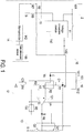
- the voltage switching module is electrically connected with the frequency control module. According to the switching signal, the voltage switching module converts the second DC voltage into an AC voltage so as to drive the piezoelectric actuator.
- the voltage dividing module is electrically connected with the voltage conversion module.
- the detecting module includes a gas pressure sensor and a microcontroller, wherein the gas pressure sensor is configured to detect a gas pressure of the piezoelectric pump and accordingly outputs plural detected gas pressure values.
- the microcontroller is electrically connected with the gas pressure sensor and the voltage dividing module to implement the following actions: acquiring an actual gas pressure change amount of the piezoelectric pump within a specified time interval by calculating the detected gas pressure values; issuing an adjusting signal to the voltage conversion module according to a result of comparing the actual gas pressure change amount with a predetermined gas pressure change amount. Then the voltage conversion module adjusts the second DC voltage according to the adjusting signal. Consequently, the gas pressure of the piezoelectric pump is correspondingly adjusted to make the actual gas pressure change amount approaching to the predetermined gas pressure change amount.
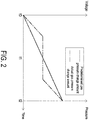
- the voltage conversion module 11 adjusts the second DC voltage Vd2 according to the adjusting signal, as a result, the gas pressure in the piezoelectric pump 16 is correspondingly adjusted, and the actual gas pressure change amount is adjusted to be close to the predetermined gas pressure change amount.
- the driving system 10 of the present invention is still capable of adjusting the actual gas pressure change amount to be close to the predetermined gas pressure change amount.
- the driving system 10 is able to output the variable second DC voltage Vd2 to the piezoelectric actuator 161 and control the working frequency of the piezoelectric actuator 161 according to the characteristics of the piezoelectric actuator 161.
- the driving system 10 of the present invention can precisely control the performance and the output flowrate of the piezoelectric pump 16, avoid damage of the piezoelectric pump 16 and increase the applicability of the piezoelectric pump 16.
- the driving system 10 of the present invention can overcome the drawbacks of the conventional technologies.
- the comparator 121 comprises a positive input terminal, a negative input terminal, and an output terminal.
- the positive input terminal of the comparator 121 is electrically connected with the input terminal A of the frequency control module 12 through the frequency adjusting circuit.
- the positive input terminal of the comparator 121 is electrically connected with the first voltage generation circuit to receive the first voltage V1.
- the negative input terminal of the comparator 121 is electrically connected with the second voltage generation circuit to receive the second voltage V2.
- the output terminal of the comparator 121 is electrically connected with the output terminal B of the frequency control module 12.
- the voltage divider inputs the first voltage V1 and the second voltage V2 into the positive input terminal and the negative input terminal of the comparator 121 respectively.
- the control circuit further comprises an output terminal voltage regulator, comprising a fifth resistor R5 and a second capacitor C2 connected with each other in parallel.
- a first terminal of the output terminal voltage regulator is connected with the second voltage generation circuit, and a second terminal of the output terminal voltage regulator is connected with the output terminal B of the frequency control module 12.
- the positive voltage V+ or the negative voltage V- as the switching signal outputted from the frequency control module 12 is stabilized by the output terminal voltage regulator.
- the frequency control module 12 receives the second DC voltage Vd2 from the voltage conversion module 11 and the control circuit of the frequency control module 12 generates the first voltage V1 and the second voltage V2.
- the first voltage V1 and the second voltage V2 are respectively inputted into the comparator 121 by which the two voltages are compared. Consequently, the comparator 121 selectively outputs the positive voltage V+ or the negative voltage V-according to the result of comparing the first voltage V1 with the second voltage V2.
Landscapes
- Engineering & Computer Science (AREA)
- Mechanical Engineering (AREA)
- General Engineering & Computer Science (AREA)
- General Electrical Machinery Utilizing Piezoelectricity, Electrostriction Or Magnetostriction (AREA)
- Reciprocating Pumps (AREA)
Claims (14)
- Pumpensystem mit einer piezoelektrischen Pumpe (16), einem piezoelektrischen Aktuator (161) und einem Treibersystem (10) zum Treiben des piezoelektrischen Aktuators (161) der piezoelektrischen Pumpe (16), wobei der piezoelektrische Aktuator (161) einen ersten Anschluss (1611) und einen zweiten Anschluss (1612) aufweist, dadurch gekennzeichnet, dass das Treibersystem (10) umfasst:ein Spannungswandler-Modul (11), das eine erste Gleichspannung (Vd1) in eine zweite Gleichspannung (Vd2) umwandelt;ein Frequenzsteuerungs-Modul (12), das elektrisch mit dem Spannungswandler-Modul (11) und dem piezoelektrischen Aktuator (161) verbunden ist, wobei das Frequenzsteuerungs-Modul (12) eine resonante Arbeitsfrequenz des piezoelektrischen Aktuators (161) durch Schaltungsoszillation sucht und ein Schaltsignal entsprechend der resonanten Arbeitsfrequenz erzeugt;ein Spannungsschalt-Modul (13), das elektrisch mit dem Frequenzsteuerungs-Modul (12) verbunden ist und die zweite Gleichspannung (Vd2) entsprechend dem Schaltsignal in eine Wechselspannung umwandelt, um den piezoelektrischen Aktuator (161) anzusteuern;ein Spannungsteiler-Modul (15), das elektrisch mit dem Spannungswandler-Modul (11) verbunden ist; undein Erfassungs-Modul (14), das einen Gasdrucksensor (141) und einen Mikrocontroller (142) umfasst, wobei der Gasdrucksensor (141) so konfiguriert ist, dass er einen Gasdruck der piezoelektrischen Pumpe (16) erfasst und dementsprechend mehrere erfasste Gasdruckwerte ausgibt, wobei der Mikrocontroller (142) elektrisch mit dem Gasdrucksensor (141) und dem Spannungsteiler-Modul (15) verbunden ist, um Aktionen zu implementieren, die Folgendes umfassen: Erfassen der tatsächlichen Größe einer Gasdruckänderung der piezoelektrischen Pumpe (16) innerhalb eines bestimmten Zeitintervalls durch Berechnen der erfassten Gasdruckwerte; Ausgeben eines Einstellsignals an das Spannungswandler-Modul (11) gemäß einem Ergebnis des Vergleichs der tatsächlichen Größe der Gasdruckänderung mit einer vorbestimmten Größe einer Gasdruckänderung;wobei das Spannungswandler-Modul (11) die zweite Gleichspannung (Vd2) gemäß dem Einstellsignal einstellt, so dass der Gasdruck der piezoelektrischen Pumpe (16) entsprechend eingestellt wird, damit sich die tatsächliche Größe der Gasdruckänderung der vorbestimmten Größe der Gasdruckänderung annähert.
- Pumpensystem nach Anspruch 1, wobei das Einstellsignal von dem Mikrocontroller (142) auf einer Spannung liegt, die direkt proportional zu der zweiten Gleichspannung (Vd2) von dem Spannungswandler-Modul (11) ist.
- Pumpensystem nach Anspruch 1, wobei das Einstellsignal von dem Mikrocontroller (142) auf einer Spannung liegt, die umgekehrt proportional zu der zweiten Gleichspannung (Vd2) von dem Spannungswandler-Modul (11) ist.
- Pumpensystem nach einem der vorhergehenden Ansprüche, wobei das Einstellsignal ein Pulsbreitenmodulationssignal ist.
- Das Pumpensystem nach einem der vorhergehenden Ansprüche, wobei, wenn die tatsächliche Größe der Gasdruckänderung größer als die vorbestimmte Größe der Gasdruckänderung ist, der Mikrocontroller (142) das Einstellsignal ausgibt, um das Spannungswandler-Modul (11) zu steuern, um die zweite Gleichspannung (Vd2) zu verringern, wobei, wenn die tatsächliche Größe der Gasdruckänderung kleiner als die vorbestimmte Größe der Gasdruckänderung ist, der Mikrocontroller (142) das Einstellsignal ausgibt, um das Spannungswandler-Modul (11) zu steuern, um die zweite Gleichspannung (Vd2) zu erhöhen.
- Pumpensystem nach einem der vorhergehenden Ansprüche, wobei das Spannungswandler-Modul (11) weiterhin einen Modus-Schalter (110) aufweist, wobei, wenn der Modus-Schalter (110) ausgeschaltet wird, das Spannungswandler-Modul (11) die Einstellung der zweiten Gleichspannung (Vd2) stoppt oder das Spannungswandler-Modul (11) deaktiviert wird.
- Pumpensystem nach einem der vorhergehenden Ansprüche, wobei das Frequenzsteuerungs-Modul (12) umfasst:einen Eingangsanschluss (A), der die zweite Gleichspannung (Vd2) von dem Spannungswandler-Modul (11) empfängt;einen Ausgangsanschluss (B), der elektrisch mit dem Spannungsschalt-Modul (13) verbunden ist;einen Empfangsanschluss (C), der elektrisch mit dem ersten Anschluss (1611) des piezoelektrischen Aktuators (161) verbunden ist, um eine Mikrospannung (Vc) von dem piezoelektrischen Aktuator (161) zu empfangen; undeine Steuerschaltung umfassend:einen Komparator (121);einen Spannungsteiler, von dem ein erster Anschluss elektrisch mit dem Empfangsanschluss (C) des Frequenzsteuerungs-Moduls (12) verbunden ist und von dem ein zweiter Anschluss elektrisch mit dem Komparator (121) verbunden ist, wobei der Spannungsteiler in eine erste Spannungserzeugungsschaltung und eine zweite Spannungserzeugungsschaltung unterteilt ist;eine Frequenzeinstellschaltung, von der ein erster Anschluss elektrisch mit dem Eingangsanschluss (A) des Frequenzsteuerungs-Moduls (12) verbunden ist und von der ein zweiter Anschluss elektrisch mit dem Spannungsteiler verbunden ist; undeinen Eingangsanschluss-Spannungsregler.
- Pumpensystem nach Anspruch 7, wobei die Frequenzeinstellschaltung der Steuerschaltung einen ersten Widerstand (R1) und einen ersten Kondensator (C1) umfasst, die parallel zueinander geschaltet sind, wobei der zweite Anschluss der Frequenzeinstellschaltung weiterhin elektrisch mit dem Komparator (121) und dem Empfangsanschluss (C) des Frequenzsteuerungs-Moduls (12) verbunden ist.
- Pumpensystem nach Anspruch 7 oder 8, wobei der Spannungsteiler der Steuerschaltung weiterhin einen zweiten Widerstand (R2) und einen dritten Widerstand (R3) umfasst, wobei die erste Spannungserzeugungsschaltung den zweiten Widerstand (R2) umfasst, eine erste Spannung (V1) erzeugt und ein erster Anschluss der ersten Spannungserzeugungsschaltung elektrisch mit einem Segment der Frequenzeinstellschaltung zwischen dem Empfangsanschluss (C) und dem Komparator (121) verbunden ist, wobei die zweite Spannungserzeugungsschaltung den dritten Widerstand (R3) umfasst, eine zweite Spannung (V2) erzeugt, ein erster Anschluss der zweiten Spannungserzeugungsschaltung elektrisch mit einem zweiten Anschluss der ersten Spannungserzeugungsschaltung verbunden ist, und ein zweiter Anschluss der zweiten Spannungserzeugungsschaltung elektrisch mit dem Komparator (121) verbunden ist, wobei der Spannungsteiler die erste Spannung (V1) und die zweite Spannung (V2) in den Komparator (121) eingibt.
- Pumpensystem nach einem der Ansprüche 7 bis 9, wobei der Eingangsanschluss-Spannungsregler der Steuerschaltung einen vierten Widerstand (R4) und einen dritten Kondensator (C3) umfasst, die parallel zueinander geschaltet sind, wobei ein erster Anschluss des Eingangsanschluss-Spannungsreglers elektrisch mit der zweiten Spannungserzeugungsschaltung des Spannungsteilers verbunden ist, ein zweiter Anschluss des Eingangsanschluss-Spannungsreglers elektrisch mit einem Masseanschluss (G) verbunden ist und die zweite Gleichspannung (Vd2) von dem Spannungswandler-Modul (11) durch den Eingangsanschluss-Spannungsregler stabilisiert wird.
- Pumpensystem nach Anspruch 9, wobei der Komparator (121) umfasst:einen positiven Eingangsanschluss, der über die Frequenzeinstellschaltung elektrisch mit dem Eingangsanschluss (A) des Frequenzsteuerungs-Moduls (12) verbunden ist und elektrisch mit der ersten Spannungserzeugungsschaltung verbunden ist, um die erste Spannung (V1) zu empfangen;einen negativen Eingangsanschluss, der elektrisch mit der zweiten Spannungserzeugungsschaltung verbunden ist, um die zweite Spannung (V2) zu empfangen; undeinen Ausgangsanschluss, der elektrisch mit dem Ausgangsanschluss (B) des Frequenzsteuerungs-Moduls (12) verbunden ist;wobei der Komparator (121) die erste Spannung (V1) mit der zweiten Spannung (V2) vergleicht und dementsprechend eine Ausgangsspannung als das Schaltsignal an den piezoelektrischen Aktuator (161) ausgibt, der piezoelektrische Aktuator (161) die Ausgangsspannung an den positiven Eingangsanschluss des Komparators (121) ausgibt, und der Komparator (121) die Ausgangsspannung mit der zweiten Spannung (V2) vergleicht, die durch den negativen Eingangsanschluss eingegeben wird, um dementsprechend die Ausgangsspannung als das Schaltsignal auszugeben, wobei die Ausgangsspannung eine positive Spannung (V+) oder eine negative Spannung (V-) ist, wobei die Frequenzeinstellschaltung und das Spannungsschalt-Modul (13) eine an den piezoelektrischen Aktuator (161) angepasste Schwingungsspannung steuern, wobei die Frequenzeinstellschaltung die Änderung der Mikrospannung (Vc) des piezoelektrischen Aktuators (161) automatisch erfasst und einstellt, so dass eine Arbeitsfrequenz des piezoelektrischen Aktuators (161) auf eine optimale Arbeitsfrequenz eingestellt wird.
- Pumpensystem nach Anspruch 11, wobei die Steuerschaltung weiterhin einen Ausgangsanschluss-Spannungsregler umfasst und der Ausgangsanschluss-Spannungsregler einen fünften Widerstand (R5) und einen zweiten Kondensator (C2) umfasst, die parallel zueinander geschaltet sind, wobei ein erster Anschluss des Ausgangsanschluss-Spannungsreglers mit der zweiten Spannungserzeugungsschaltung verbunden ist, ein zweiter Anschluss des Ausgangsanschluss-Spannungsreglers mit dem Ausgangsanschluss (B) des Frequenzsteuerungs-Moduls (12) verbunden ist und die Ausgangsspannung als das von dem Frequenzsteuerungs-Modul (12) ausgegebene Schaltsignal durch den Ausgangsanschluss-Spannungsregler stabilisiert wird.
- Pumpensystem nach einem der vorhergehenden Ansprüche, wobei das Spannungsschalt-Modul (13) elektrisch mit einem Ausgangsanschluss (B) des Frequenzsteuerungs-Moduls (12) verbunden ist und das Spannungsschalt-Modul (13) umfasst:einen ersten Schalter (Q1) mit einem Steueranschluss zum Empfangen der zweiten Gleichspannung (Vd2) von dem Spannungswandler-Modul (11);einen zweiten Schalter (Q2) mit einem Eingangsanschluss und einem Ausgangsanschluss, die beide mit dem ersten Schalter (Q1) in Verbindung stehen, wobei der Eingangsanschluss mit dem Ausgangsanschluss (B) des Frequenzsteuerungs-Moduls (12) verbunden ist, der Ausgangsanschluss mit dem zweiten Anschluss (1612) des piezoelektrischen Aktuators (161) verbunden ist und der zweite Schalter (Q2) weiterhin einen Steueranschluss aufweist, der mit einem Masseanschluss (G) verbunden ist; undeinen sechsten Widerstand (R6), von dem ein erster Anschluss mit dem Ausgangsanschluss (B) des Frequenzsteuerungs-Moduls (12) verbunden ist und von dem ein zweiter Anschluss mit dem zweiten Anschluss (1612) des piezoelektrischen Aktuators (161) verbunden ist.
- Pumpensystem nach einem der vorhergehenden Ansprüche, wobei das Spannungsteiler-Modul (15) umfasst:einen siebten Widerstand (R7), von dem ein erster Anschluss elektrisch mit dem Mikrocontroller (142) verbunden ist, um das Einstellsignal zu empfangen;einen achten Widerstand (R8), von dem ein erster Anschluss elektrisch mit einem zweiten Anschluss des siebten Widerstandes (R7) verbunden ist und von dem ein zweiter Anschluss elektrisch mit dem Spannungswandler-Modul (11) verbunden ist; undeinen neunten Widerstand (R9), von dem ein erster Anschluss elektrisch mit dem zweiten Anschluss des achten Widerstandes (R8) verbunden ist, und von dem ein zweiter Anschluss elektrisch mit einem Erdungsanschluss (G) verbunden ist.
Applications Claiming Priority (1)
| Application Number | Priority Date | Filing Date | Title |
|---|---|---|---|
| TW105133015A TWI606686B (zh) | 2016-10-13 | 2016-10-13 | 壓電泵浦之驅動系統 |
Publications (2)
| Publication Number | Publication Date |
|---|---|
| EP3309396A1 EP3309396A1 (de) | 2018-04-18 |
| EP3309396B1 true EP3309396B1 (de) | 2020-12-23 |
Family
ID=60083188
Family Applications (1)
| Application Number | Title | Priority Date | Filing Date |
|---|---|---|---|
| EP17196101.4A Active EP3309396B1 (de) | 2016-10-13 | 2017-10-12 | Antriebssystem für piezoelektrische pumpe |
Country Status (4)
| Country | Link |
|---|---|
| US (1) | US10883485B2 (de) |
| EP (1) | EP3309396B1 (de) |
| JP (1) | JP6617129B2 (de) |
| TW (1) | TWI606686B (de) |
Families Citing this family (6)
| Publication number | Priority date | Publication date | Assignee | Title |
|---|---|---|---|---|
| TWI605681B (zh) * | 2016-10-13 | 2017-11-11 | 研能科技股份有限公司 | 壓電泵浦之驅動系統 |
| TWI697200B (zh) * | 2019-04-03 | 2020-06-21 | 研能科技股份有限公司 | 微型壓電泵模組 |
| TWI712258B (zh) * | 2019-08-19 | 2020-12-01 | 研能科技股份有限公司 | 微型壓電泵模組 |
| CN112392699B (zh) * | 2019-08-19 | 2023-01-24 | 研能科技股份有限公司 | 微型压电泵模块 |
| TWI720876B (zh) * | 2020-04-24 | 2021-03-01 | 研能科技股份有限公司 | 驅動壓電式泵浦的驅動電路系統 |
| JPWO2025013405A1 (de) * | 2023-07-07 | 2025-01-16 |
Family Cites Families (12)
| Publication number | Priority date | Publication date | Assignee | Title |
|---|---|---|---|---|
| JPS62186077A (ja) * | 1986-02-10 | 1987-08-14 | Misuzu Erii:Kk | 圧電ポンプの駆動方法 |
| JP4293189B2 (ja) | 2004-03-10 | 2009-07-08 | セイコーエプソン株式会社 | 圧電アクチュエータ駆動装置、電子機器、電子機器の駆動方法 |
| CN1906843B (zh) * | 2004-03-17 | 2010-09-29 | 精工爱普生株式会社 | 压电致动器驱动装置、电子设备、其驱动方法 |
| US7312554B2 (en) * | 2004-04-02 | 2007-12-25 | Adaptivenergy, Llc | Piezoelectric devices and methods and circuits for driving same |
| US7290993B2 (en) | 2004-04-02 | 2007-11-06 | Adaptivenergy Llc | Piezoelectric devices and methods and circuits for driving same |
| US7287965B2 (en) | 2004-04-02 | 2007-10-30 | Adaptiv Energy Llc | Piezoelectric devices and methods and circuits for driving same |
| US7484940B2 (en) | 2004-04-28 | 2009-02-03 | Kinetic Ceramics, Inc. | Piezoelectric fluid pump |
| JP4487662B2 (ja) | 2004-07-12 | 2010-06-23 | セイコーエプソン株式会社 | 圧電アクチュエータの駆動方法、圧電アクチュエータの駆動装置、電子機器 |
| EP2469089A1 (de) | 2010-12-23 | 2012-06-27 | Debiotech S.A. | Elektronisches Steuerungsverfahren und System für eine piezoelektrische Pumpe |
| US8896182B2 (en) * | 2012-04-05 | 2014-11-25 | General Electric Corporation | System for driving a piezoelectric load and method of making same |
| US8958217B2 (en) | 2012-06-15 | 2015-02-17 | General Electric Company | System for driving a piezoelectric load and method of making same |
| TWI605681B (zh) * | 2016-10-13 | 2017-11-11 | 研能科技股份有限公司 | 壓電泵浦之驅動系統 |
-
2016
- 2016-10-13 TW TW105133015A patent/TWI606686B/zh active
-
2017
- 2017-10-12 EP EP17196101.4A patent/EP3309396B1/de active Active
- 2017-10-12 JP JP2017198123A patent/JP6617129B2/ja active Active
- 2017-10-12 US US15/782,482 patent/US10883485B2/en active Active
Non-Patent Citations (1)
| Title |
|---|
| None * |
Also Published As
| Publication number | Publication date |
|---|---|
| JP6617129B2 (ja) | 2019-12-11 |
| TWI606686B (zh) | 2017-11-21 |
| US10883485B2 (en) | 2021-01-05 |
| TW201815050A (zh) | 2018-04-16 |
| JP2018062936A (ja) | 2018-04-19 |
| US20180106245A1 (en) | 2018-04-19 |
| EP3309396A1 (de) | 2018-04-18 |
Similar Documents
| Publication | Publication Date | Title |
|---|---|---|
| US10883485B2 (en) | Driving system for piezoelectric pump | |
| EP3309395B1 (de) | Piezoelektrische pumpe | |
| CN103155390B (zh) | 功率转换器 | |
| US9502990B2 (en) | Electric power feedback apparatus with main power output-feedback and standby power output-feedback | |
| CN112260550B (zh) | 隔离谐振变换器及其控制方法 | |
| US7768227B2 (en) | Efficiency maximization control and variable speed drive of single phase induction motors | |
| US20130234527A1 (en) | Wireless electric power transmission device | |
| US11075545B2 (en) | System and method for actively controlling output voltage of a wireless power transfer system | |
| US20170288462A1 (en) | Wireless Power Supply Device, Wireless Power Receiving Device and Wireless Power Transmission System | |
| US12395088B2 (en) | Input responsive protection and frequency control of series connected converters | |
| EP3098959B1 (de) | Piezoelektrisches stromerzeugungsmodul und fernsteuerung | |
| EP3187731B1 (de) | Treiberschaltung für piezoelektrisch angetriebene pumpe | |
| EP4236622A3 (de) | Induktionsheizvorrichtung mit verbesserter ausgangssteuerfunktion | |
| CN107939658A (zh) | 压电泵的驱动系统 | |
| EP1739819B1 (de) | System mit einem gas-laser-oszillator und einer stromversorgungs-vorrichtung | |
| US8692536B2 (en) | Switching regulator with short-circuit detection circuit | |
| TWM545188U (zh) | 壓電泵浦之驅動系統 | |
| JP2018023190A (ja) | スイッチング電源装置 | |
| US20250282246A1 (en) | Control circuit and method of electric vehicle supply equipment | |
| GB2419478A (en) | Parallel connected power converters having current and voltage control modes | |
| TWI580151B (zh) | 感應式電源供應器之供電模組及其輸出功率調節方法 | |
| CN120303865A (zh) | 直流变压器设备和用于运行直流变压器设备的方法 | |
| CN104980049A (zh) | 电力反馈装置及电力反馈方法 |
Legal Events
| Date | Code | Title | Description |
|---|---|---|---|
| PUAI | Public reference made under article 153(3) epc to a published international application that has entered the european phase |
Free format text: ORIGINAL CODE: 0009012 |
|
| STAA | Information on the status of an ep patent application or granted ep patent |
Free format text: STATUS: THE APPLICATION HAS BEEN PUBLISHED |
|
| AK | Designated contracting states |
Kind code of ref document: A1 Designated state(s): AL AT BE BG CH CY CZ DE DK EE ES FI FR GB GR HR HU IE IS IT LI LT LU LV MC MK MT NL NO PL PT RO RS SE SI SK SM TR |
|
| AX | Request for extension of the european patent |
Extension state: BA ME |
|
| STAA | Information on the status of an ep patent application or granted ep patent |
Free format text: STATUS: REQUEST FOR EXAMINATION WAS MADE |
|
| 17P | Request for examination filed |
Effective date: 20181001 |
|
| RBV | Designated contracting states (corrected) |
Designated state(s): AL AT BE BG CH CY CZ DE DK EE ES FI FR GB GR HR HU IE IS IT LI LT LU LV MC MK MT NL NO PL PT RO RS SE SI SK SM TR |
|
| GRAP | Despatch of communication of intention to grant a patent |
Free format text: ORIGINAL CODE: EPIDOSNIGR1 |
|
| STAA | Information on the status of an ep patent application or granted ep patent |
Free format text: STATUS: GRANT OF PATENT IS INTENDED |
|
| INTG | Intention to grant announced |
Effective date: 20200930 |
|
| GRAS | Grant fee paid |
Free format text: ORIGINAL CODE: EPIDOSNIGR3 |
|
| GRAA | (expected) grant |
Free format text: ORIGINAL CODE: 0009210 |
|
| STAA | Information on the status of an ep patent application or granted ep patent |
Free format text: STATUS: THE PATENT HAS BEEN GRANTED |
|
| AK | Designated contracting states |
Kind code of ref document: B1 Designated state(s): AL AT BE BG CH CY CZ DE DK EE ES FI FR GB GR HR HU IE IS IT LI LT LU LV MC MK MT NL NO PL PT RO RS SE SI SK SM TR |
|
| REG | Reference to a national code |
Ref country code: GB Ref legal event code: FG4D |
|
| REG | Reference to a national code |
Ref country code: DE Ref legal event code: R096 Ref document number: 602017029914 Country of ref document: DE |
|
| REG | Reference to a national code |
Ref country code: AT Ref legal event code: REF Ref document number: 1347981 Country of ref document: AT Kind code of ref document: T Effective date: 20210115 |
|
| REG | Reference to a national code |
Ref country code: IE Ref legal event code: FG4D |
|
| PG25 | Lapsed in a contracting state [announced via postgrant information from national office to epo] |
Ref country code: NO Free format text: LAPSE BECAUSE OF FAILURE TO SUBMIT A TRANSLATION OF THE DESCRIPTION OR TO PAY THE FEE WITHIN THE PRESCRIBED TIME-LIMIT Effective date: 20210323 Ref country code: RS Free format text: LAPSE BECAUSE OF FAILURE TO SUBMIT A TRANSLATION OF THE DESCRIPTION OR TO PAY THE FEE WITHIN THE PRESCRIBED TIME-LIMIT Effective date: 20201223 Ref country code: FI Free format text: LAPSE BECAUSE OF FAILURE TO SUBMIT A TRANSLATION OF THE DESCRIPTION OR TO PAY THE FEE WITHIN THE PRESCRIBED TIME-LIMIT Effective date: 20201223 Ref country code: GR Free format text: LAPSE BECAUSE OF FAILURE TO SUBMIT A TRANSLATION OF THE DESCRIPTION OR TO PAY THE FEE WITHIN THE PRESCRIBED TIME-LIMIT Effective date: 20210324 |
|
| REG | Reference to a national code |
Ref country code: AT Ref legal event code: MK05 Ref document number: 1347981 Country of ref document: AT Kind code of ref document: T Effective date: 20201223 |
|
| REG | Reference to a national code |
Ref country code: NL Ref legal event code: MP Effective date: 20201223 |
|
| PG25 | Lapsed in a contracting state [announced via postgrant information from national office to epo] |
Ref country code: SE Free format text: LAPSE BECAUSE OF FAILURE TO SUBMIT A TRANSLATION OF THE DESCRIPTION OR TO PAY THE FEE WITHIN THE PRESCRIBED TIME-LIMIT Effective date: 20201223 Ref country code: BG Free format text: LAPSE BECAUSE OF FAILURE TO SUBMIT A TRANSLATION OF THE DESCRIPTION OR TO PAY THE FEE WITHIN THE PRESCRIBED TIME-LIMIT Effective date: 20210323 Ref country code: LV Free format text: LAPSE BECAUSE OF FAILURE TO SUBMIT A TRANSLATION OF THE DESCRIPTION OR TO PAY THE FEE WITHIN THE PRESCRIBED TIME-LIMIT Effective date: 20201223 |
|
| PG25 | Lapsed in a contracting state [announced via postgrant information from national office to epo] |
Ref country code: HR Free format text: LAPSE BECAUSE OF FAILURE TO SUBMIT A TRANSLATION OF THE DESCRIPTION OR TO PAY THE FEE WITHIN THE PRESCRIBED TIME-LIMIT Effective date: 20201223 Ref country code: NL Free format text: LAPSE BECAUSE OF FAILURE TO SUBMIT A TRANSLATION OF THE DESCRIPTION OR TO PAY THE FEE WITHIN THE PRESCRIBED TIME-LIMIT Effective date: 20201223 |
|
| REG | Reference to a national code |
Ref country code: LT Ref legal event code: MG9D |
|
| PG25 | Lapsed in a contracting state [announced via postgrant information from national office to epo] |
Ref country code: PT Free format text: LAPSE BECAUSE OF FAILURE TO SUBMIT A TRANSLATION OF THE DESCRIPTION OR TO PAY THE FEE WITHIN THE PRESCRIBED TIME-LIMIT Effective date: 20210423 Ref country code: RO Free format text: LAPSE BECAUSE OF FAILURE TO SUBMIT A TRANSLATION OF THE DESCRIPTION OR TO PAY THE FEE WITHIN THE PRESCRIBED TIME-LIMIT Effective date: 20201223 Ref country code: SK Free format text: LAPSE BECAUSE OF FAILURE TO SUBMIT A TRANSLATION OF THE DESCRIPTION OR TO PAY THE FEE WITHIN THE PRESCRIBED TIME-LIMIT Effective date: 20201223 Ref country code: SM Free format text: LAPSE BECAUSE OF FAILURE TO SUBMIT A TRANSLATION OF THE DESCRIPTION OR TO PAY THE FEE WITHIN THE PRESCRIBED TIME-LIMIT Effective date: 20201223 Ref country code: EE Free format text: LAPSE BECAUSE OF FAILURE TO SUBMIT A TRANSLATION OF THE DESCRIPTION OR TO PAY THE FEE WITHIN THE PRESCRIBED TIME-LIMIT Effective date: 20201223 Ref country code: CZ Free format text: LAPSE BECAUSE OF FAILURE TO SUBMIT A TRANSLATION OF THE DESCRIPTION OR TO PAY THE FEE WITHIN THE PRESCRIBED TIME-LIMIT Effective date: 20201223 Ref country code: LT Free format text: LAPSE BECAUSE OF FAILURE TO SUBMIT A TRANSLATION OF THE DESCRIPTION OR TO PAY THE FEE WITHIN THE PRESCRIBED TIME-LIMIT Effective date: 20201223 |
|
| PG25 | Lapsed in a contracting state [announced via postgrant information from national office to epo] |
Ref country code: PL Free format text: LAPSE BECAUSE OF FAILURE TO SUBMIT A TRANSLATION OF THE DESCRIPTION OR TO PAY THE FEE WITHIN THE PRESCRIBED TIME-LIMIT Effective date: 20201223 Ref country code: AT Free format text: LAPSE BECAUSE OF FAILURE TO SUBMIT A TRANSLATION OF THE DESCRIPTION OR TO PAY THE FEE WITHIN THE PRESCRIBED TIME-LIMIT Effective date: 20201223 |
|
| REG | Reference to a national code |
Ref country code: DE Ref legal event code: R097 Ref document number: 602017029914 Country of ref document: DE |
|
| PG25 | Lapsed in a contracting state [announced via postgrant information from national office to epo] |
Ref country code: IS Free format text: LAPSE BECAUSE OF FAILURE TO SUBMIT A TRANSLATION OF THE DESCRIPTION OR TO PAY THE FEE WITHIN THE PRESCRIBED TIME-LIMIT Effective date: 20210423 |
|
| PG25 | Lapsed in a contracting state [announced via postgrant information from national office to epo] |
Ref country code: IT Free format text: LAPSE BECAUSE OF FAILURE TO SUBMIT A TRANSLATION OF THE DESCRIPTION OR TO PAY THE FEE WITHIN THE PRESCRIBED TIME-LIMIT Effective date: 20201223 Ref country code: AL Free format text: LAPSE BECAUSE OF FAILURE TO SUBMIT A TRANSLATION OF THE DESCRIPTION OR TO PAY THE FEE WITHIN THE PRESCRIBED TIME-LIMIT Effective date: 20201223 |
|
| PLBE | No opposition filed within time limit |
Free format text: ORIGINAL CODE: 0009261 |
|
| STAA | Information on the status of an ep patent application or granted ep patent |
Free format text: STATUS: NO OPPOSITION FILED WITHIN TIME LIMIT |
|
| PG25 | Lapsed in a contracting state [announced via postgrant information from national office to epo] |
Ref country code: DK Free format text: LAPSE BECAUSE OF FAILURE TO SUBMIT A TRANSLATION OF THE DESCRIPTION OR TO PAY THE FEE WITHIN THE PRESCRIBED TIME-LIMIT Effective date: 20201223 |
|
| 26N | No opposition filed |
Effective date: 20210924 |
|
| PG25 | Lapsed in a contracting state [announced via postgrant information from national office to epo] |
Ref country code: ES Free format text: LAPSE BECAUSE OF FAILURE TO SUBMIT A TRANSLATION OF THE DESCRIPTION OR TO PAY THE FEE WITHIN THE PRESCRIBED TIME-LIMIT Effective date: 20201223 |
|
| PG25 | Lapsed in a contracting state [announced via postgrant information from national office to epo] |
Ref country code: SI Free format text: LAPSE BECAUSE OF FAILURE TO SUBMIT A TRANSLATION OF THE DESCRIPTION OR TO PAY THE FEE WITHIN THE PRESCRIBED TIME-LIMIT Effective date: 20201223 |
|
| REG | Reference to a national code |
Ref country code: CH Ref legal event code: PL |
|
| PG25 | Lapsed in a contracting state [announced via postgrant information from national office to epo] |
Ref country code: IS Free format text: LAPSE BECAUSE OF FAILURE TO SUBMIT A TRANSLATION OF THE DESCRIPTION OR TO PAY THE FEE WITHIN THE PRESCRIBED TIME-LIMIT Effective date: 20210423 |
|
| REG | Reference to a national code |
Ref country code: BE Ref legal event code: MM Effective date: 20211031 |
|
| PG25 | Lapsed in a contracting state [announced via postgrant information from national office to epo] |
Ref country code: MC Free format text: LAPSE BECAUSE OF FAILURE TO SUBMIT A TRANSLATION OF THE DESCRIPTION OR TO PAY THE FEE WITHIN THE PRESCRIBED TIME-LIMIT Effective date: 20201223 |
|
| PG25 | Lapsed in a contracting state [announced via postgrant information from national office to epo] |
Ref country code: LU Free format text: LAPSE BECAUSE OF NON-PAYMENT OF DUE FEES Effective date: 20211012 Ref country code: BE Free format text: LAPSE BECAUSE OF NON-PAYMENT OF DUE FEES Effective date: 20211031 |
|
| PG25 | Lapsed in a contracting state [announced via postgrant information from national office to epo] |
Ref country code: LI Free format text: LAPSE BECAUSE OF NON-PAYMENT OF DUE FEES Effective date: 20211031 Ref country code: CH Free format text: LAPSE BECAUSE OF NON-PAYMENT OF DUE FEES Effective date: 20211031 |
|
| PG25 | Lapsed in a contracting state [announced via postgrant information from national office to epo] |
Ref country code: FR Free format text: LAPSE BECAUSE OF NON-PAYMENT OF DUE FEES Effective date: 20211031 |
|
| PG25 | Lapsed in a contracting state [announced via postgrant information from national office to epo] |
Ref country code: IE Free format text: LAPSE BECAUSE OF NON-PAYMENT OF DUE FEES Effective date: 20211012 |
|
| PG25 | Lapsed in a contracting state [announced via postgrant information from national office to epo] |
Ref country code: HU Free format text: LAPSE BECAUSE OF FAILURE TO SUBMIT A TRANSLATION OF THE DESCRIPTION OR TO PAY THE FEE WITHIN THE PRESCRIBED TIME-LIMIT; INVALID AB INITIO Effective date: 20171012 |
|
| PG25 | Lapsed in a contracting state [announced via postgrant information from national office to epo] |
Ref country code: CY Free format text: LAPSE BECAUSE OF FAILURE TO SUBMIT A TRANSLATION OF THE DESCRIPTION OR TO PAY THE FEE WITHIN THE PRESCRIBED TIME-LIMIT Effective date: 20201223 |
|
| PG25 | Lapsed in a contracting state [announced via postgrant information from national office to epo] |
Ref country code: MK Free format text: LAPSE BECAUSE OF FAILURE TO SUBMIT A TRANSLATION OF THE DESCRIPTION OR TO PAY THE FEE WITHIN THE PRESCRIBED TIME-LIMIT Effective date: 20201223 |
|
| PG25 | Lapsed in a contracting state [announced via postgrant information from national office to epo] |
Ref country code: MT Free format text: LAPSE BECAUSE OF FAILURE TO SUBMIT A TRANSLATION OF THE DESCRIPTION OR TO PAY THE FEE WITHIN THE PRESCRIBED TIME-LIMIT Effective date: 20201223 |
|
| PGFP | Annual fee paid to national office [announced via postgrant information from national office to epo] |
Ref country code: GB Payment date: 20250912 Year of fee payment: 9 |
|
| PG25 | Lapsed in a contracting state [announced via postgrant information from national office to epo] |
Ref country code: TR Free format text: LAPSE BECAUSE OF FAILURE TO SUBMIT A TRANSLATION OF THE DESCRIPTION OR TO PAY THE FEE WITHIN THE PRESCRIBED TIME-LIMIT Effective date: 20201223 |
|
| PGFP | Annual fee paid to national office [announced via postgrant information from national office to epo] |
Ref country code: DE Payment date: 20250912 Year of fee payment: 9 |