EP3309394B1 - Verfahren zur herstellung eines kugelgelenks zwischen einem kolben und einem gleitschuh einer hydrostatische verdrängermaschine - Google Patents
Verfahren zur herstellung eines kugelgelenks zwischen einem kolben und einem gleitschuh einer hydrostatische verdrängermaschine Download PDFInfo
- Publication number
- EP3309394B1 EP3309394B1 EP17193758.4A EP17193758A EP3309394B1 EP 3309394 B1 EP3309394 B1 EP 3309394B1 EP 17193758 A EP17193758 A EP 17193758A EP 3309394 B1 EP3309394 B1 EP 3309394B1
- Authority
- EP
- European Patent Office
- Prior art keywords
- piston
- ball
- calotte
- sliding block
- displacement machine
- Prior art date
- Legal status (The legal status is an assumption and is not a legal conclusion. Google has not performed a legal analysis and makes no representation as to the accuracy of the status listed.)
- Active
Links
Images
Classifications
-
- F—MECHANICAL ENGINEERING; LIGHTING; HEATING; WEAPONS; BLASTING
- F04—POSITIVE - DISPLACEMENT MACHINES FOR LIQUIDS; PUMPS FOR LIQUIDS OR ELASTIC FLUIDS
- F04B—POSITIVE-DISPLACEMENT MACHINES FOR LIQUIDS; PUMPS
- F04B1/00—Multi-cylinder machines or pumps characterised by number or arrangement of cylinders
- F04B1/12—Multi-cylinder machines or pumps characterised by number or arrangement of cylinders having cylinder axes coaxial with, or parallel or inclined to, main shaft axis
- F04B1/20—Multi-cylinder machines or pumps characterised by number or arrangement of cylinders having cylinder axes coaxial with, or parallel or inclined to, main shaft axis having rotary cylinder block
- F04B1/2014—Details or component parts
- F04B1/2035—Cylinder barrels
-
- F—MECHANICAL ENGINEERING; LIGHTING; HEATING; WEAPONS; BLASTING
- F04—POSITIVE - DISPLACEMENT MACHINES FOR LIQUIDS; PUMPS FOR LIQUIDS OR ELASTIC FLUIDS
- F04B—POSITIVE-DISPLACEMENT MACHINES FOR LIQUIDS; PUMPS
- F04B1/00—Multi-cylinder machines or pumps characterised by number or arrangement of cylinders
- F04B1/12—Multi-cylinder machines or pumps characterised by number or arrangement of cylinders having cylinder axes coaxial with, or parallel or inclined to, main shaft axis
- F04B1/20—Multi-cylinder machines or pumps characterised by number or arrangement of cylinders having cylinder axes coaxial with, or parallel or inclined to, main shaft axis having rotary cylinder block
- F04B1/2014—Details or component parts
-
- F—MECHANICAL ENGINEERING; LIGHTING; HEATING; WEAPONS; BLASTING
- F04—POSITIVE - DISPLACEMENT MACHINES FOR LIQUIDS; PUMPS FOR LIQUIDS OR ELASTIC FLUIDS
- F04B—POSITIVE-DISPLACEMENT MACHINES FOR LIQUIDS; PUMPS
- F04B1/00—Multi-cylinder machines or pumps characterised by number or arrangement of cylinders
- F04B1/12—Multi-cylinder machines or pumps characterised by number or arrangement of cylinders having cylinder axes coaxial with, or parallel or inclined to, main shaft axis
- F04B1/20—Multi-cylinder machines or pumps characterised by number or arrangement of cylinders having cylinder axes coaxial with, or parallel or inclined to, main shaft axis having rotary cylinder block
- F04B1/2014—Details or component parts
- F04B1/2078—Swash plates
Definitions
- the invention relates to a method for producing a ball joint between a piston and a sliding shoe of a hydrostatic displacement machine, in particular an axial piston machine, the sliding shoe being articulated to the piston by means of the ball joint, the ball joint consisting of a ball and a dome, and the attachment the ball in the dome takes place through a form-fitting connection in which an edge area of the dome is deformed in order to enclose the ball in a form-fitting manner.
- Hydrostatic displacement machines in particular axial piston machines, have sliding shoes in the area where the pistons are supported on a running surface that generates a stroke.
- the sliding shoes are each articulated to the pressurized piston by means of a ball joint.
- the ball-and-socket joint, with which the sliding shoe is articulated to the corresponding piston, consists of a ball and a spherical cap.
- the ball is fastened in the dome by means of a form-fitting connection, in that an edge region of the dome is deformed and thus reshaped in order to enclose the ball in a form-fitting manner.
- the deformation and thus reshaping of the edge area of the dome in order to fix the ball in an articulated manner in the dome is carried out in known hydrostatic displacement machines by flanging or by roller burnishing, the edge area of the dome being rolled up radially inward.
- the flanging or roller burnishing has a long cycle time, so that the form-fitting connection between the piston and sliding shoe is correspondingly complex.
- rollers which are used as tools for reshaping the edge region of the dome by flanging or roller burnishing, are exposed to high mechanical forces, so that they are subject to wear and the service life of the rollers is limited.
- the production of the form-fitting connection between the piston and sliding shoe known hydrostatic displacement machines by means of flanging or roller burnishing thus leads to a high production cost of the form-fitting connection between the piston and slide shoe.
- a generic method for producing a ball joint between the piston and slide shoe of a hydrostatic displacement machine in which the edge area of the spherical cap is deformed in order to enclose the ball head of the ball in a form-fitting manner.
- the edge area of the dome is elastically deformed and expanded when the spherical head is pressed into the dome in the manner of a snap lock.
- the DE 42 14 765 A1 discloses a ball-and-socket joint between the piston and the slide shoe of a hydrostatic displacement machine, in which the ball is partially flattened to form a cylinder and can be inserted into the dome at a certain mounting angle. After the sliding shoe has subsequently been tilted, the ball is then held in a form-fitting manner in the dome.
- the DE 10 2010 036 199 A1 discloses a hydrostatic displacement machine with a ball joint connection between the piston and the sliding shoe.
- the DE 199 11 121 A1 discloses a link arm with two cylinder sleeves or ball joints as joints at the ends.
- the link arm is for a motor vehicle and has a deformable portion that can easily deform in the event of a collision / impact of the motor vehicle in order to absorb energy.
- the deformable section is designed as a squeezed wall section in the central area - seen in the longitudinal direction - of the link arm, which is produced by plastic deformation, for example electromagnetic molding.
- the holders of the cylinder liners are attached to the two ends of the link arm using fusion welding, laser welding or friction welding.
- the US 2004/0174014 A1 discloses in Figure 6 the connection of two pipes by means of a ball joint.
- the ball joint has an outer hood with a first cylindrical sleeve, the cylindrical sleeve being attached to the first pipeline at the axial end by means of magnetic pulse welding (Magnetic Pulse Welding MPW) in order to create a seal, and an inner hood with a second cylindrical sleeve, wherein the cylindrical sleeve is attached at the axial end to the second pipeline by means of magnetic pulse welding in order to create a seal.
- magnetic pulse welding Magnetic Pulse Welding MPW
- the present invention is based on the object of providing a method for producing a ball joint between a piston and a slide shoe of a hydrostatic displacement machine of the type mentioned, in which the positive connection between the piston and slide shoe is produced with little manufacturing effort.
- the form-fitting connection of the ball in the dome is produced by magnetic pulse forming, the ball being inserted into the dome to create the form-fitting connection between the piston and sliding shoe and then the outer edge region of the dome radially inward by means of magnetic pulse forming is deformed and reshaped so that the ball is positively enclosed and held in an articulated manner in the dome.
- the positive connection between the piston and the slide shoe of the hydrostatic displacement machine is thus produced by magnetic pulse forming.
- magnetic pulse forming With magnetic pulse forming, a magnetic pulse is generated, the energy input of which deforms the outer edge area of the dome and thus reshapes it in order to enclose the ball in a form-fitting manner.
- magnetic pulse forming By means of magnetic pulse forming, compared to rolling or flanging, a shorter cycle time can be achieved in the production of the form-fitting connection between the piston and slide shoe. In addition, there is no wear and tear on tools during magnetic pulse forming. Furthermore, the spherical gap in the ball joint between the ball and the spherical cap for the form-fitting connection between the piston and the sliding block can be optimized and reproducibly produced. Overall, magnetic pulse forming thus enables the positive connection between the piston and the slide shoe to be established with little manufacturing effort.
- a hydrostatic displacement machine in particular an axial piston machine, with a cylinder drum rotatably arranged about an axis of rotation, which is provided with at least one piston recess, in each of which a piston is arranged to be longitudinally displaceable and by a sliding shoe that is articulated on the piston by means of a ball joint on a stroke generating Running surface is supported, wherein the ball joint consists of a ball and a spherical cap, and the attachment of the ball in the spherical cap is carried out by a positive connection by means of magnetic pulse forming, the spherical cap on the piston and the ball can be formed on the slide shoe or, alternatively, the dome can be formed on the slide shoe and the ball on the piston.
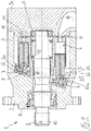
- FIG. 1 shows a hydrostatic displacement machine 1 with positive connections produced according to the invention on ball joints 25 between piston 5 and sliding blocks 6 in a longitudinal section.
- the illustrated embodiment shows an axial piston machine in swash plate design as an example of a hydrostatic displacement machine 1.
- Form-fitting connections made according to the invention on the ball joints between pistons and sliding blocks can also be used in axial piston machines in bent axis design or in radial piston machines.
- the displacement machine 1 has a cylinder drum 3 rotatably mounted about an axis of rotation 2, which is provided with several piston recesses 4 arranged concentrically to the axis of rotation 2, which are preferably formed by cylinder bores and in each of which a piston 5 is longitudinally displaceable.
- the pistons 5 are supported in the area protruding from the cylinder drum 3 by means of a sliding shoe 6 as a support element on a stroke-generating one Running surface 7, which is formed by a swash plate 8 arranged in a rotationally fixed manner about the axis of rotation 2.
- the swash plate 8 can be attached to a housing 9 of the displacement machine 1 - as in FIG Figure 1 is shown - be integrally formed or non-rotatably attached, the displacement machine 1 having a fixed displacement volume.
- the cylinder drum 3 is supported in the axial direction of the displacement machine 1 opposite the running surface 7 on a housing-side distributor 10 which forms a control surface 11.
- the control surface 11 is provided with kidney-shaped control recesses which enable an inlet channel 14 and an outlet channel 13 in the housing 9 to be connected to the piston recesses 4.
- the distributor 10 can be formed by a disk-shaped component which is fastened in a rotationally fixed manner to the housing 9, for example a housing cover 9a of the housing 9.
- the distributor 10 can be integrally formed on the housing 9, for example a housing cover 9a of the housing 9, so that the function of the control surface 11 is integrated into the housing 9, 9a.
- control surface 11 can as in Figure 1 be shown flat or spherical.
- the cylinder drum 3 is penetrated by a central bore through which a drive shaft 15 arranged concentrically to the axis of rotation 2 is guided through the cylinder drum 3.
- the drive shaft 15 is rotatably mounted in the housing 9, 9a by means of bearings 16, 17.
- the cylinder drum 3 is non-rotatably connected to the drive shaft 15 by means of driving teeth 18, but is axially displaceable. Also shown is a pressure spring 19 which presses the cylinder drum 3 in the axial direction against the control surface 11 and supports it.
- the sliding shoes 6 and the running surface 7 form a plain bearing point at which a relative movement occurs between the sliding shoes 6 rotating with the cylinder drum 3 and the piston 5 and the running surface 7 that is fixedly attached to the housing 9.
- a bearing metal layer 6b for example a brass plate, as a tribologically favorable bearing metal material, is joined to the sliding shoes 6 on the end face facing the running surface 7.
- the sliding shoes 6 on the running surface 7 are hydrostatically relieved.
- the hold-down device 20 is designed as a hold-down disk which interacts with contact surfaces on the slide shoe 6.
- the slide shoes 6 are articulated to the respective piston 5 by means of a slide shoe joint designed as a ball joint 25.
- the ball joint 25 between the piston 5 and the sliding shoe 6 consists of a ball 26 and a dome 27.
- the ball 26 is fastened in the dome 27 by a form-fitting connection in which an edge area 27a of the dome 27 is deformed around the ball 26 to enclose form-fitting.
- the positive connection of the ball 26 in the dome 27 is produced by magnetic pulse forming, the edge region 27a of the dome 27 being deformed radially inward by magnetic pulse forming.
- a magnetic pulse is generated, the energy input of which causes the outer edge region 27a of the spherical cap 27 to be deformed radially inward and thus reshaped in order to enclose the ball 26 with a form fit.
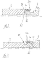
- the outer edge area 27a of the spherical cap 27 is shown with dashed lines in the undeformed state before the magnetic pulse forming and in solid lines in the deformed state after the magnetic pulse forming.
- the ball 26 is inserted into the spherical cap 27 and then the outer edge area 27a of the spherical cap 27 is deformed radially inward by magnetic pulse forming and thus reshaped so that the ball 26 is positively enclosed and in the The calotte 27 is articulated.
- the piston 5 with the sliding shoe 6 is inserted in the area of the outer edge area 27a of the spherical cap 27 into an annular coil, on which a magnetic field (electromagnetic pulse) is generated during magnetic pulse forming.
- a magnetic field electromagnettic pulse
- the outer edge region 27a of the spherical cap 27 is formed radially inward.
- magnetic pulse forming By means of magnetic pulse forming, a shorter cycle time for producing the form-fitting connection between the piston 5 and the sliding block 6 can be achieved compared to rolling or flanging. In addition, there is no wear and tear on tools during magnetic pulse forming. Furthermore, a spherical gap 30 in the ball joint between the ball 26 and the spherical cap 26 for the form-fitting connection between the piston 5 and the slide shoe 5 can be optimized and reproducibly produced by adjusting the magnetic field. Overall, magnetic pulse forming thus enables the positive connection between piston 5 and slide shoe 6 to be produced with little production effort.
Landscapes
- Engineering & Computer Science (AREA)
- Mechanical Engineering (AREA)
- General Engineering & Computer Science (AREA)
- Reciprocating Pumps (AREA)
- Compressors, Vaccum Pumps And Other Relevant Systems (AREA)
Description
- Die Erfindung betrifft ein Verfahren zur Herstellung eines Kugelgelenks zwischen einem Kolben und einem Gleitschuh einer hydrostatischen Verdrängermaschine, insbesondere einer Axialkolbenmaschine, wobei der Gleitschuh mittels des Kugelgelenks an dem Kolben gelenkig befestigt ist, wobei das Kugelgelenk aus einer Kugel und einer Kalotte besteht, und die Befestigung der Kugel in der Kalotte durch eine formschlüssige Verbindung erfolgt, in dem ein Randbereich der Kalotte verformt wird, um die Kugel formschlüssig zu umschließen.
- Hydrostatische Verdrängermaschinen, insbesondere Axialkolbenmaschinen, weisen im Bereich der Abstützung der Kolben an einer huberzeugenden Lauffläche Gleitschuhe auf. Die Gleitschuhe sind an den druckbeaufschlagten Kolben jeweils mittels eines Kugelgelenks gelenkig befestigt. Das Kugelgelenk, mit dem der Gleitschuh an dem entsprechenden Kolben gelenkig befestigt ist, besteht aus einer Kugel und einer Kalotte. Die Befestigung der Kugel in der Kalotte erfolgt bei bekannten hydrostatischen Verdrängermaschinen durch eine formschlüssige Verbindung, indem ein Randbereich der Kalotte verformt und somit umgeformt wird, um die Kugel formschlüssig zu umschließen. Das Verformen und somit Umformen des Randbereichs der Kalotte, um die Kugel in der Kalotte gelenkig zu befestigen, erfolgt bei bekannten hydrostatische Verdrängermaschinen durch Bördeln oder durch Rollieren, wobei der Randbereich der Kalotte nach radial Innen eingerollt wird. Die Herstellung der formschlüssigen Verbindung zwischen Kolben und Gleitschuh durch Einrollen des Randbereichs der Kalotte, beispielsweise durch Bördeln oder durch Rollieren, erfordert jedoch eine aufwändige Handhabung der Bauteile Kolben und Gleitschuh. Weiterhin weist das Bördeln oder Rollieren eine hohe Taktzeit auf, so dass die formschlüssige Verbindung zwischen Kolben und Gleitschuh entsprechend aufwändig ist. Zudem sind die Walzen, die zum Umformen des Randbereichs der Kalotte durch Bördeln oder durch Rollieren als Werkzeug verwendet werden, hohen mechanischen Kräften ausgesetzt, so dass diese einem Verschleiß ausgesetzt sind und die Standzeit der Walzen begrenzt ist. Die Herstellung der formschlüssigen Verbindung zwischen Kolben und Gleitschuh bei bekannten hydrostatischen Verdrängermaschinen mittels Bördeln oder Rollieren führt somit zu einem hohen Herstellaufwand der formschlüssigen Verbindung zwischen Kolben und Gleitschuh.
- Aus der
DE 197 12 838 A1 ist ein gattungsgemäßes Verfahren zur Herstellung eines Kugelgelenks zwischen Kolben und Gleitschuh einer hydrostatischen Verdrängermaschine bekannt, bei dem der Randbereich der Kalotte verformt wird, um den Kugelkopf der Kugel formschlüssig zu umschließen. Hierzu wird der Randbereich der Kalotte elastisch verformt und aufgeweitet, wenn der Kugelkopf nach Art eines Schnappverschlusses in die Kalotte hineingedrückt wird. - Die
DE 42 14 765 A1 offenbart eine Kugelgelenkverbindung zwischen Kolben und Gleitschuh einer hydrostatische Verdrängermaschine, bei der die Kugel partiell zu einem Zylinder abgeflacht ist und unter einem bestimmten Montagewinkel in die Kalotte eingeführt werden kann. Nach anschließendem Verkippen des Gleitschuhs ist die Kugel dann in der Kalotte formschlüssig gehaltert. - Die
DE 10 2010 036 199 A1 offenbart eine hydrostatische Verdrängermaschine mit einer Kugelgelenkverbindung zwischen Kolben und Gleitschuh. - Die
DE 199 11 121 A1 offenbart einen Lenkerarm mit zwei Zylinderbuchsen oder Kugelgelenken als Gelenke an den Enden. Der Lenkerarm ist für ein Kraftfahrzeug und weist einen verformbaren Abschnitt auf, der bei einem Zusammenstoß/Aufprall des Kraftfahrzeugs leicht verformen kann, um Energie zu absorbieren. Der verformbare Abschnitt ist als gequetschter Wandabschnitt im mittleren Bereich - in Längsrichtung gesehen - des Lenkerarms ausgebildet, der durch ein plastisches Umformen hergestellt wird, beispielsweise elektromagnetisches Formen. An den beiden Enden des Lenkerarms werden die Halter der Zylinderbuchsen mittels Schmelzschweißen, Laserschweißen oder Reibschweißvorgangs befestigt. - Die
US 2004/0174014 A1 offenbart in der Figur 6 die Verbindung zweier Rohrleitungen mittels eines Kugelgelenks. Das Kugelgelenk weist eine äußere Haube mit einer ersten zylindrischen Hülse auf, wobei die zylindrische Hülse am axialen Ende mittels Magnetpulsschweißen (Magnetic Pulse Welding MPW) an der ersten Rohrleitung befestigt ist, um eine Abdichtung zu erzeugen, und eine innere Haube mit einer zweiten zylindrischen Hülse auf, wobei die zylindrische Hülse am axialen Ende mittels Magnetpulsschweißen an der zweiten Rohrleitung befestigt ist, um eine Abdichtung zu erzeugen. - Der vorliegenden Erfindung liegt die Aufgabe zugrunde, ein Verfahren zur Herstellung eines Kugelgelenks zwischen einem Kolben und einem Gleitschuh einer hydrostatische Verdrängermaschine der eingangs genannten Gattung zur Verfügung zu stellen, bei dem die formschlüssige Verbindung zwischen Kolben und Gleitschuh mit geringem Herstellaufwand erzeugt wird.
- Diese Aufgabe wird erfindungsgemäß dadurch gelöst, dass die formschlüssige Verbindung der Kugel in der Kalotte durch Magnetpulsumformen erzeugt wird, wobei zur Erzeugung der formschlüssigen Verbindung zwischen Kolben und Gleitschuh die Kugel in die Kalotte eingeführt wird und anschließend durch Magnetpulsumformen der äußere Randbereich der Kalotte nach radial innen verformt und umgeformt wird, so dass die Kugel formschlüssig umschlossen wird und in der Kalotte gelenkig gehalten ist. Erfindungsgemäß wird somit die formschlüssige Verbindung zwischen Kolben und Gleitschuh der hydrostatischen Verdrängermaschine durch Magnetpulsumformen erzeugt. Beim Magnetpulsumformen wird ein magnetischer Puls erzeugt, durch dessen Energieeintrag der äußere Randbereich der Kalotte verformt und somit umgeformt wird, um die Kugel formschlüssig zu umschließen. Durch Magnetpulsumformen kann gegenüber einem Rollieren oder Bördeln eine kürzere Taktzeit bei der Herstellung der formschlüssigen Verbindung zwischen Kolben und Gleitschuh erzielt werden. Zudem tritt beim Magnetpulsumformen kein Verschleiß an Werkzeugen auf. Weiterhin kann der sphärische Spalt in dem Kugelgelenk zwischen Kugel und Kalotte zur formschlüssigen Verbindung zwischen Kolben und Gleitschuh optimiert und reproduzierbar erzeugt werden. Insgesamt ermöglicht somit das Magnetpulsumformen die Herstellung der formschlüssigen Verbindung zwischen Kolben und Gleitschuh mit geringem Herstellaufwand.
- Bei einer hydrostatische Verdrängermaschine, insbesondere einer Axialkolbenmaschine, mit einer um eine Drehachse drehbar angeordneten Zylindertrommel, die mit mindestens einer Kolbenausnehmung versehen ist, in der jeweils ein Kolben längsverschiebbar angeordnet ist und durch einen mittels eines Kugelgelenks am Kolben gelenkig befestigten Gleitschuh an einer huberzeugenden Lauffläche abgestützt ist, wobei das Kugelgelenk aus einer Kugel und einer Kalotte besteht, und die Befestigung der Kugel in der Kalotte durch eine formschlüssige Verbindung mittels Magnetpulsumformen erfolgt, kann die Kalotte an dem Kolben und die Kugel an dem Gleitschuh ausgebildet sein oder alternativ die Kalotte an dem Gleitschuh und die Kugel an dem Kolben ausgebildet sein.
- Weitere Vorteile und Einzelheiten der Erfindung werden anhand der in den schematischen Figuren dargestellten Ausführungsbeispiele näher erläutert. Hierbei zeigt
- Figur 1
- eine hydrostatisches Verdrängermaschine mit erfindungsgemäß hergestellten formschlüssigen Verbindungen an den Kugelgelenken zwischen Kolben und Gleitschuhen in einem Längsschnitt,
- Figur 2
- eine erste Ausführungsform einer erfindungsgemäß hergestellten formschlüssigen Verbindung an dem Kugelgelenk zwischen Kolben und Gleitschuh und
- Figur 3
- eine zweite Ausführungsform einer erfindungsgemäß hergestellten formschlüssigen Verbindung an dem Kugelgelenk zwischen Kolben und Gleitschuh.
- In der
Figur 1 ist eine hydrostatische Verdrängermaschine 1 mit erfindungsgemäß hergestellten formschlüssigen Verbindungen an Kugelgelenken 25 zwischen Kolben 5 und Gleitschuhen 6 in einem Längsschnitt dargestellt. Das dargestellte Ausführungsbeispiel zeigt eine Axialkolbenmaschine in Schrägscheibenbauweise als Beispiel einer hydrostatischen Verdrängermaschine 1. Erfindungsgemäß hergestellte formschlüssigen Verbindungen an den Kugelgelenken zwischen Kolben und Gleitschuhen können ebenfalls bei Axialkolbenmaschine in Schrägachsenbauweise oder bei Radialkolbenmaschinen Verwendung finden. - Die Verdrängermaschine 1 weist eine um eine Drehachse 2 drehbar gelagerte Zylindertrommel 3 auf, die mit mehreren konzentrisch zur Drehachse 2 angeordneten Kolbenausnehmungen 4 versehen ist, die bevorzugt von Zylinderbohrungen gebildet sind und in denen jeweils ein Kolben 5 längsverschiebbar gelagert ist.
- Die Kolben 5 stützen sich in dem aus der Zylindertrommel 3 herausragenden Bereich mittels jeweils eines Gleitschuhs 6 als Abstützelements auf einer huberzeugenden Lauffläche 7 ab, die von einer um die Drehachse 2 drehfest angeordneten Schrägscheibe 8 gebildet ist.
- Die Schrägscheibe 8 kann an einem Gehäuse 9 der Verdrängermaschine 1 - wie in der
Figur 1 dargestellt ist - angeformt oder drehfest befestigt sein, wobei die Verdrängermaschine 1 ein festes Verdrängungsvolumen aufweist. - Es ist alternativ möglich, die Schrägscheibe 8 in der Neigung verstellbar anzuordnen, wodurch die Verdrängermaschine 1 ein veränderbares Verdrängungsvolumen aufweist.
- Die Zylindertrommel 3 stützt sich in axialer Richtung der Verdrängermaschine 1 gegenüberliegend zu der Lauffläche 7 an einem gehäuseseitigen Verteiler 10 ab, der eine Steuerfläche 11 bildet. Die Steuerfläche 11 ist mit nierenförmigen Steuerausnehmungen versehen, die die Verbindung eines Einlasskanals 14 und eines Auslasskanals 13 im Gehäuse 9 mit den Kolbenausnehmungen 4 ermöglichen.
- Der Verteiler 10 kann von einem scheibenförmigen Bauteil gebildet werden, das an dem Gehäuse 9, beispielsweise einem Gehäusedeckel 9a des Gehäuses 9, drehfest befestigt ist. Alternativ kann der Verteiler 10 an dem Gehäuse 9, beispielsweise einem Gehäusedeckel 9a des Gehäuses 9 einstückig angeformt werden, so dass die Funktion der Steuerfläche 11 in das Gehäuse 9, 9a integriert ist.
- Die Steuerfläche 11 kann wie in der
Figur 1 dargestellt eben oder auch sphärisch sein. - Die Zylindertrommel 3 ist von einer zentrischen Bohrung durchsetzt, durch die eine konzentrisch zur Drehachse 2 angeordnete Triebwelle 15 durch die Zylindertrommel 3 geführt ist. Die Triebwelle 15 ist mittels Lagerungen 16, 17 im Gehäuse 9, 9a drehbar gelagert.
- Die Zylindertrommel 3 ist mittels einer Mitnahmeverzahnung 18 mit der Triebwelle 15 drehfest, jedoch axial verschiebbar verbunden. Weiterhin dargestellt ist eine Anpressfeder 19, die die Zylindertrommel 3 in axialer Richtung an die Steuerfläche 11 anpresst und abstützt.
- Im Betrieb der Verdrängermaschine 1 bei rotierender Zylindertrommel 3 bilden die Gleitschuhe 6 und die Lauffläche 7 eine Gleitlagerstelle, an der zwischen den mit der Zylindertrommel 3 und den Kolben 5 mitrotierenden Gleitschuhen 6 und der drehfest am Gehäuse 9 befestigten Lauffläche 7 eine Relativbewegung auftritt. Zur Verringerung der Reibung und des Verschleißes ist an den Gleitschuhen 6 an der der Lauffläche 7 zugewandten Stirnseite jeweils eine Lagermetallschicht 6b, beispielsweise eine Messingplatte, als tribologisch günstiger Lagermetallwerkstoff gefügt. Zusätzlich sind die Gleitschuhe 6 an der Lauffläche 7 hydrostatisch entlastet.
- Ein Abheben und/oder Abkippen der Gleitschuhe 6 von der Lauffläche 7 wird durch eine Niederhaltevorrichtung 20 vermieden. Die Niederhaltevorrichtung 20 ist im dargestellten Ausführungsbeispiel als Niederhaltescheibe ausgebildet, die mit Anlageflächen an dem Gleitschuh 6 zusammenwirkt.
- Die Gleitschuhe 6 sind mittels eines als Kugelgelenk 25 ausgebildeten Gleitschuhgelenks mit dem jeweiligen Kolben 5 gelenkig verbunden.
- Das Kugelgelenk 25 zwischen dem Kolben 5 und dem Gleitschuh 6 besteht aus einer Kugel 26 und einer Kalotte 27. Die Befestigung der Kugel 26 in der Kalotte 27 erfolgt durch eine formschlüssige Verbindung, in dem ein Randbereich 27a der Kalotte 27 verformt wird, um die Kugel 26 formschlüssig zu umschließen.
- Erfindungsgemäß wird die formschlüssige Verbindung der Kugel 26 in der Kalotte 27 durch Magnetpulsumformen erzeugt, wobei durch Magnetpulsumformen der Randbereich 27a der Kalotte 27 nach radial Innen verformt wird. Beim Magnetpulsumformen wird ein magnetischer Puls erzeugt, durch dessen Energieeintrag der äußere Randbereich 27a der Kalotte 27 nach radial Innen verformt und somit umgeformt wird, um die Kugel 26 formschlüssig zu umschließen.
- In der
Figur 2 ist eine Ausführungsform dargestellt, bei der die Kugel 26 des Kugelgelenks 25 an dem Gleitschuh 6 und die Kugelkalotte 27 des Kugelgelenks 25 an dem Kolben 5 ausgebildet ist. - In der
Figur 3 ist eine Ausführungsform dargestellt, bei der die Kugel 26 des Kugelgelenks 25 an dem Kolben 5 und die Kugelkalotte 27 des Kugelgelenks 25 an Gleitschuh 6 ausgebildet ist. - In den
Figuren 2 und 3 ist jeweils der äußere Randbereich 27a der Kalotte 27 mit gestrichelten Linien im unverformten Zustand vor dem Magnetpulsumformen und in durchgezogenen Linien im verformten Zustand nach dem Magnetpulsumformen dargestellt. - Zur Erzeugung der formschlüssigen Verbindung zwischen Kolben 5 und Gleitschuh 6 wird die Kugel 26 in die Kalotte 27 eingeführt und anschließend durch Magnetpulsumformen der äußere Randbereich 27a der Kalotte 27 nach radial Innen verformt und somit umgeformt, so dass die Kugel 26 formschlüssig umschlossen wird und in der Kalotte 27 gelenkig gehalten ist.
- Der Kolben 5 mit dem Gleitschuh 6 wird hierzu im Bereich des äußere Randbereich 27a der Kalotte 27 in eine ringförmige Spule eingeführt, an der beim Magnetpulsumformen ein Magnetfeld (elektromagnetischer Puls) erzeugt wird. Durch Aufbringen des Magnetfeldes beim Magnetpulsumformen wird der äußere Randbereich 27a der Kalotte 27 nach radial Innen umgeformt.
- Durch Magnetpulsumformen kann gegenüber einem Rollieren oder Bördeln eine kürzere Taktzeit zum Erzeugen der formschlüssigen Verbindung zwischen dem Kolben 5 und dem Gleitschuh 6 erzielt werden. Zudem tritt beim Magnetpulsumformen kein Verschleiß an Werkzeugen auf. Weiterhin kann ein sphärischer Spalt 30 in dem Kugelgelenk zwischen Kugel 26 und Kalotte 26 zur formschlüssigen Verbindung zwischen Kolben 5 und Gleitschuh 5 durch Einstellen des Magnetfeldes optimiert und reproduzierbar erzeugt werden. Insgesamt ermöglicht somit das Magnetpulsumformen die Herstellung der formschlüssigen Verbindung zwischen Kolben 5 und Gleitschuh 6 mit geringem Herstellaufwand.
Claims (1)
- Verfahren zur Herstellung eines Kugelgelenks (25) zwischen einem Kolben (5) und einem Gleitschuh (6) einer hydrostatischen Verdrängermaschine (1), insbesondere einer Axialkolbenmaschine, wobei der Gleitschuh (6) mittels des Kugelgelenks (25) an dem Kolben (5) gelenkig befestigt ist, wobei das Kugelgelenk (25) aus einer Kugel (26) und einer Kalotte (27) besteht, und die Befestigung der Kugel (26) in der Kalotte (27) durch eine formschlüssige Verbindung erfolgt, in dem ein Randbereich (27a) der Kalotte (27) verformt wird, um die Kugel (26) formschlüssig zu umschließen, dadurch gekennzeichnet, dass die formschlüssige Verbindung der Kugel (26) in der Kalotte (27) durch Magnetpulsumformen erzeugt wird, wobei zur Erzeugung der formschlüssigen Verbindung zwischen Kolben (5) und Gleitschuh (6) die Kugel (26) in die Kalotte (27) eingeführt wird und anschließend durch Magnetpulsumformen der äußere Randbereich (27a) der Kalotte (27) nach radial innen verformt und umgeformt wird, so dass die Kugel (26) formschlüssig umschlossen wird und in der Kalotte (27) gelenkig gehalten ist.
Applications Claiming Priority (1)
| Application Number | Priority Date | Filing Date | Title |
|---|---|---|---|
| DE102016119412.3A DE102016119412A1 (de) | 2016-10-12 | 2016-10-12 | Verfahren zur Herstellung eines Kugelgelenks zwischen einem Kolben und einem Gleitschuh einer hydrostatische Verdrängermaschine |
Publications (2)
| Publication Number | Publication Date |
|---|---|
| EP3309394A1 EP3309394A1 (de) | 2018-04-18 |
| EP3309394B1 true EP3309394B1 (de) | 2020-12-30 |
Family
ID=59974337
Family Applications (1)
| Application Number | Title | Priority Date | Filing Date |
|---|---|---|---|
| EP17193758.4A Active EP3309394B1 (de) | 2016-10-12 | 2017-09-28 | Verfahren zur herstellung eines kugelgelenks zwischen einem kolben und einem gleitschuh einer hydrostatische verdrängermaschine |
Country Status (2)
| Country | Link |
|---|---|
| EP (1) | EP3309394B1 (de) |
| DE (1) | DE102016119412A1 (de) |
Families Citing this family (3)
| Publication number | Priority date | Publication date | Assignee | Title |
|---|---|---|---|---|
| CN110701038A (zh) * | 2018-07-10 | 2020-01-17 | 江苏可奈力机械制造有限公司 | 一种耐磨防开裂倒包柱塞结构 |
| CN116163906B (zh) * | 2022-12-16 | 2024-12-13 | 合肥工业大学 | 一种无需压板的浮动斜盘式锥形柱塞变量泵旋转组件 |
| CN117514681B (zh) * | 2023-10-27 | 2025-10-31 | 合肥工业大学 | 含有主轴等速驱动回转盘传动机构的浮动斜盘式柱塞泵 |
Family Cites Families (5)
| Publication number | Priority date | Publication date | Assignee | Title |
|---|---|---|---|---|
| DE4214765A1 (de) * | 1992-05-04 | 1993-11-11 | Sachsenhydraulik Gmbh | Kolben-Gleitschuh Verbindung für hydro-statische Maschinen |
| DE19712838C2 (de) * | 1997-03-26 | 1999-03-18 | Brueninghaus Hydromatik Gmbh | Verfahren zum Herstellen einer Kugelgelenkverbindung |
| US6298962B1 (en) * | 1998-03-13 | 2001-10-09 | Showa Denko K.K. | Member for arm |
| US20040174014A1 (en) * | 2003-03-07 | 2004-09-09 | Storage Michael R. | Hose assembly and method of making |
| DE102010036199B4 (de) * | 2010-09-02 | 2021-11-18 | Linde Hydraulics Gmbh & Co. Kg | Axialkolbenmaschine mit verringerter Verlustleistung durch Verwendung geeigneter Dichtmittel im Bereich der Schrägscheibenausnehmung |
-
2016
- 2016-10-12 DE DE102016119412.3A patent/DE102016119412A1/de not_active Withdrawn
-
2017
- 2017-09-28 EP EP17193758.4A patent/EP3309394B1/de active Active
Non-Patent Citations (1)
| Title |
|---|
| None * |
Also Published As
| Publication number | Publication date |
|---|---|
| EP3309394A1 (de) | 2018-04-18 |
| DE102016119412A1 (de) | 2018-04-12 |
Similar Documents
| Publication | Publication Date | Title |
|---|---|---|
| EP1138875B1 (de) | Verfahren zum Herstellen einer Kugelgelenkverbindung | |
| DE10300070A1 (de) | Axialkolbenmaschine, Rückzugplatte und Verfahren zum Herstellen einer Rückzugplatte | |
| EP3309394A1 (de) | Verfahren zur herstellung eines kugelgelenks zwischen einem kolben und einem gleitschuh einer hydrostatische verdrängermaschine | |
| EP2180964B1 (de) | Verfahren zum umformen eines hohlteils | |
| DE102014007050A1 (de) | Kolbenmaschine mit einem Pleuelschaft aus mehreren Teilen | |
| EP3055565B1 (de) | Schrägscheibenmaschine | |
| DE102017121425A1 (de) | Pleuel für eine Brennkraftmaschine mit variabler Verdichtung | |
| WO2007045203A1 (de) | Lagereinheit, vorzugsweise radlagereinheit für ein kraftfahrzeug, sowie verfahren zur herstellung einer lagereinheit | |
| WO2008068095A1 (de) | Verfahren zur befestigung einer hülse auf einer welle | |
| DE102013203787A1 (de) | Schrägscheibenmaschine | |
| EP3309392B1 (de) | Verfahren zur herstellung eines gleitschuhs einer hydrostatischen verdrängermaschine | |
| EP3309393B1 (de) | Hydrostatische verdrängermaschine | |
| DE102015206716A1 (de) | Schrägscheibenmaschine | |
| DE19955321A1 (de) | Rundknetmaschine mit hydraulischem Kraftausgleich | |
| EP3676495B1 (de) | Herstellungsverfahren, kolbenrohling, kolben sowie axialkolbenmaschine mit dem kolben | |
| EP1561031B1 (de) | AXIALKOLBENMASCHINE, R üCKZUGPLATTE UND VERFAHREN ZUM HERSTELLEN EINER RüCKZUGPLATTE | |
| DE10102989C2 (de) | Fügeverfahren für eine Kugelgelenkverbindung | |
| EP3339602B1 (de) | Pleuel für eine brennkraftmaschine mit variabler verdichtung | |
| DE102015112478B4 (de) | Verfahren zur Herstellung einer Verbindung zwischen einem lokal aufgeweiteten rohrförmigen Element und wenigstens einem darauf aufzubringenden Nabenelement | |
| DE102016213904B4 (de) | Kolben-Zylinder-Einheit | |
| WO2014206683A1 (de) | Hohlkolben für eine schrägscheibenmaschine und schrägscheibenmaschine | |
| DE102022210175A1 (de) | Verfahren zum Herstellen einer Antriebswelle, Biegerichteinrichtung und Antriebswelle | |
| WO2014206682A1 (de) | Hohlkolben für eine schrägscheibenmaschine und schrägscheibenmaschine | |
| WO2015086260A1 (de) | Schrägscheibenmaschine | |
| DE102013202295A1 (de) | Schrägscheibenmaschine |
Legal Events
| Date | Code | Title | Description |
|---|---|---|---|
| PUAI | Public reference made under article 153(3) epc to a published international application that has entered the european phase |
Free format text: ORIGINAL CODE: 0009012 |
|
| STAA | Information on the status of an ep patent application or granted ep patent |
Free format text: STATUS: THE APPLICATION HAS BEEN PUBLISHED |
|
| AK | Designated contracting states |
Kind code of ref document: A1 Designated state(s): AL AT BE BG CH CY CZ DE DK EE ES FI FR GB GR HR HU IE IS IT LI LT LU LV MC MK MT NL NO PL PT RO RS SE SI SK SM TR |
|
| AX | Request for extension of the european patent |
Extension state: BA ME |
|
| STAA | Information on the status of an ep patent application or granted ep patent |
Free format text: STATUS: REQUEST FOR EXAMINATION WAS MADE |
|
| 17P | Request for examination filed |
Effective date: 20181015 |
|
| RBV | Designated contracting states (corrected) |
Designated state(s): AL AT BE BG CH CY CZ DE DK EE ES FI FR GB GR HR HU IE IS IT LI LT LU LV MC MK MT NL NO PL PT RO RS SE SI SK SM TR |
|
| GRAP | Despatch of communication of intention to grant a patent |
Free format text: ORIGINAL CODE: EPIDOSNIGR1 |
|
| STAA | Information on the status of an ep patent application or granted ep patent |
Free format text: STATUS: GRANT OF PATENT IS INTENDED |
|
| INTG | Intention to grant announced |
Effective date: 20200703 |
|
| GRAS | Grant fee paid |
Free format text: ORIGINAL CODE: EPIDOSNIGR3 |
|
| GRAA | (expected) grant |
Free format text: ORIGINAL CODE: 0009210 |
|
| STAA | Information on the status of an ep patent application or granted ep patent |
Free format text: STATUS: THE PATENT HAS BEEN GRANTED |
|
| AK | Designated contracting states |
Kind code of ref document: B1 Designated state(s): AL AT BE BG CH CY CZ DE DK EE ES FI FR GB GR HR HU IE IS IT LI LT LU LV MC MK MT NL NO PL PT RO RS SE SI SK SM TR |
|
| REG | Reference to a national code |
Ref country code: GB Ref legal event code: FG4D Free format text: NOT ENGLISH |
|
| REG | Reference to a national code |
Ref country code: AT Ref legal event code: REF Ref document number: 1350186 Country of ref document: AT Kind code of ref document: T Effective date: 20210115 |
|
| REG | Reference to a national code |
Ref country code: DE Ref legal event code: R096 Ref document number: 502017008817 Country of ref document: DE |
|
| REG | Reference to a national code |
Ref country code: IE Ref legal event code: FG4D Free format text: LANGUAGE OF EP DOCUMENT: GERMAN |
|
| PG25 | Lapsed in a contracting state [announced via postgrant information from national office to epo] |
Ref country code: NO Free format text: LAPSE BECAUSE OF FAILURE TO SUBMIT A TRANSLATION OF THE DESCRIPTION OR TO PAY THE FEE WITHIN THE PRESCRIBED TIME-LIMIT Effective date: 20210330 Ref country code: RS Free format text: LAPSE BECAUSE OF FAILURE TO SUBMIT A TRANSLATION OF THE DESCRIPTION OR TO PAY THE FEE WITHIN THE PRESCRIBED TIME-LIMIT Effective date: 20201230 Ref country code: FI Free format text: LAPSE BECAUSE OF FAILURE TO SUBMIT A TRANSLATION OF THE DESCRIPTION OR TO PAY THE FEE WITHIN THE PRESCRIBED TIME-LIMIT Effective date: 20201230 Ref country code: GR Free format text: LAPSE BECAUSE OF FAILURE TO SUBMIT A TRANSLATION OF THE DESCRIPTION OR TO PAY THE FEE WITHIN THE PRESCRIBED TIME-LIMIT Effective date: 20210331 |
|
| PG25 | Lapsed in a contracting state [announced via postgrant information from national office to epo] |
Ref country code: SE Free format text: LAPSE BECAUSE OF FAILURE TO SUBMIT A TRANSLATION OF THE DESCRIPTION OR TO PAY THE FEE WITHIN THE PRESCRIBED TIME-LIMIT Effective date: 20201230 Ref country code: LV Free format text: LAPSE BECAUSE OF FAILURE TO SUBMIT A TRANSLATION OF THE DESCRIPTION OR TO PAY THE FEE WITHIN THE PRESCRIBED TIME-LIMIT Effective date: 20201230 Ref country code: BG Free format text: LAPSE BECAUSE OF FAILURE TO SUBMIT A TRANSLATION OF THE DESCRIPTION OR TO PAY THE FEE WITHIN THE PRESCRIBED TIME-LIMIT Effective date: 20210330 |
|
| REG | Reference to a national code |
Ref country code: NL Ref legal event code: MP Effective date: 20201230 |
|
| PG25 | Lapsed in a contracting state [announced via postgrant information from national office to epo] |
Ref country code: HR Free format text: LAPSE BECAUSE OF FAILURE TO SUBMIT A TRANSLATION OF THE DESCRIPTION OR TO PAY THE FEE WITHIN THE PRESCRIBED TIME-LIMIT Effective date: 20201230 |
|
| REG | Reference to a national code |
Ref country code: LT Ref legal event code: MG9D |
|
| PG25 | Lapsed in a contracting state [announced via postgrant information from national office to epo] |
Ref country code: LT Free format text: LAPSE BECAUSE OF FAILURE TO SUBMIT A TRANSLATION OF THE DESCRIPTION OR TO PAY THE FEE WITHIN THE PRESCRIBED TIME-LIMIT Effective date: 20201230 Ref country code: CZ Free format text: LAPSE BECAUSE OF FAILURE TO SUBMIT A TRANSLATION OF THE DESCRIPTION OR TO PAY THE FEE WITHIN THE PRESCRIBED TIME-LIMIT Effective date: 20201230 Ref country code: EE Free format text: LAPSE BECAUSE OF FAILURE TO SUBMIT A TRANSLATION OF THE DESCRIPTION OR TO PAY THE FEE WITHIN THE PRESCRIBED TIME-LIMIT Effective date: 20201230 Ref country code: SK Free format text: LAPSE BECAUSE OF FAILURE TO SUBMIT A TRANSLATION OF THE DESCRIPTION OR TO PAY THE FEE WITHIN THE PRESCRIBED TIME-LIMIT Effective date: 20201230 Ref country code: PT Free format text: LAPSE BECAUSE OF FAILURE TO SUBMIT A TRANSLATION OF THE DESCRIPTION OR TO PAY THE FEE WITHIN THE PRESCRIBED TIME-LIMIT Effective date: 20210430 Ref country code: RO Free format text: LAPSE BECAUSE OF FAILURE TO SUBMIT A TRANSLATION OF THE DESCRIPTION OR TO PAY THE FEE WITHIN THE PRESCRIBED TIME-LIMIT Effective date: 20201230 |
|
| PG25 | Lapsed in a contracting state [announced via postgrant information from national office to epo] |
Ref country code: PL Free format text: LAPSE BECAUSE OF FAILURE TO SUBMIT A TRANSLATION OF THE DESCRIPTION OR TO PAY THE FEE WITHIN THE PRESCRIBED TIME-LIMIT Effective date: 20201230 |
|
| PG25 | Lapsed in a contracting state [announced via postgrant information from national office to epo] |
Ref country code: IS Free format text: LAPSE BECAUSE OF FAILURE TO SUBMIT A TRANSLATION OF THE DESCRIPTION OR TO PAY THE FEE WITHIN THE PRESCRIBED TIME-LIMIT Effective date: 20210430 |
|
| REG | Reference to a national code |
Ref country code: DE Ref legal event code: R097 Ref document number: 502017008817 Country of ref document: DE |
|
| PG25 | Lapsed in a contracting state [announced via postgrant information from national office to epo] |
Ref country code: IT Free format text: LAPSE BECAUSE OF FAILURE TO SUBMIT A TRANSLATION OF THE DESCRIPTION OR TO PAY THE FEE WITHIN THE PRESCRIBED TIME-LIMIT Effective date: 20201230 Ref country code: AL Free format text: LAPSE BECAUSE OF FAILURE TO SUBMIT A TRANSLATION OF THE DESCRIPTION OR TO PAY THE FEE WITHIN THE PRESCRIBED TIME-LIMIT Effective date: 20201230 |
|
| PLBE | No opposition filed within time limit |
Free format text: ORIGINAL CODE: 0009261 |
|
| STAA | Information on the status of an ep patent application or granted ep patent |
Free format text: STATUS: NO OPPOSITION FILED WITHIN TIME LIMIT |
|
| PG25 | Lapsed in a contracting state [announced via postgrant information from national office to epo] |
Ref country code: DK Free format text: LAPSE BECAUSE OF FAILURE TO SUBMIT A TRANSLATION OF THE DESCRIPTION OR TO PAY THE FEE WITHIN THE PRESCRIBED TIME-LIMIT Effective date: 20201230 |
|
| 26N | No opposition filed |
Effective date: 20211001 |
|
| PG25 | Lapsed in a contracting state [announced via postgrant information from national office to epo] |
Ref country code: ES Free format text: LAPSE BECAUSE OF FAILURE TO SUBMIT A TRANSLATION OF THE DESCRIPTION OR TO PAY THE FEE WITHIN THE PRESCRIBED TIME-LIMIT Effective date: 20201230 |
|
| PG25 | Lapsed in a contracting state [announced via postgrant information from national office to epo] |
Ref country code: SI Free format text: LAPSE BECAUSE OF FAILURE TO SUBMIT A TRANSLATION OF THE DESCRIPTION OR TO PAY THE FEE WITHIN THE PRESCRIBED TIME-LIMIT Effective date: 20201230 |
|
| REG | Reference to a national code |
Ref country code: CH Ref legal event code: PL |
|
| REG | Reference to a national code |
Ref country code: BE Ref legal event code: MM Effective date: 20210930 |
|
| GBPC | Gb: european patent ceased through non-payment of renewal fee |
Effective date: 20210928 |
|
| PG25 | Lapsed in a contracting state [announced via postgrant information from national office to epo] |
Ref country code: IS Free format text: LAPSE BECAUSE OF FAILURE TO SUBMIT A TRANSLATION OF THE DESCRIPTION OR TO PAY THE FEE WITHIN THE PRESCRIBED TIME-LIMIT Effective date: 20210430 Ref country code: MC Free format text: LAPSE BECAUSE OF FAILURE TO SUBMIT A TRANSLATION OF THE DESCRIPTION OR TO PAY THE FEE WITHIN THE PRESCRIBED TIME-LIMIT Effective date: 20201230 |
|
| PG25 | Lapsed in a contracting state [announced via postgrant information from national office to epo] |
Ref country code: LU Free format text: LAPSE BECAUSE OF NON-PAYMENT OF DUE FEES Effective date: 20210928 Ref country code: IE Free format text: LAPSE BECAUSE OF NON-PAYMENT OF DUE FEES Effective date: 20210928 Ref country code: GB Free format text: LAPSE BECAUSE OF NON-PAYMENT OF DUE FEES Effective date: 20210928 Ref country code: FR Free format text: LAPSE BECAUSE OF NON-PAYMENT OF DUE FEES Effective date: 20210930 Ref country code: BE Free format text: LAPSE BECAUSE OF NON-PAYMENT OF DUE FEES Effective date: 20210930 |
|
| PG25 | Lapsed in a contracting state [announced via postgrant information from national office to epo] |
Ref country code: LI Free format text: LAPSE BECAUSE OF NON-PAYMENT OF DUE FEES Effective date: 20210930 Ref country code: CH Free format text: LAPSE BECAUSE OF NON-PAYMENT OF DUE FEES Effective date: 20210930 |
|
| PG25 | Lapsed in a contracting state [announced via postgrant information from national office to epo] |
Ref country code: HU Free format text: LAPSE BECAUSE OF FAILURE TO SUBMIT A TRANSLATION OF THE DESCRIPTION OR TO PAY THE FEE WITHIN THE PRESCRIBED TIME-LIMIT; INVALID AB INITIO Effective date: 20170928 |
|
| P01 | Opt-out of the competence of the unified patent court (upc) registered |
Effective date: 20230514 |
|
| PG25 | Lapsed in a contracting state [announced via postgrant information from national office to epo] |
Ref country code: NL Free format text: LAPSE BECAUSE OF NON-PAYMENT OF DUE FEES Effective date: 20201230 Ref country code: CY Free format text: LAPSE BECAUSE OF FAILURE TO SUBMIT A TRANSLATION OF THE DESCRIPTION OR TO PAY THE FEE WITHIN THE PRESCRIBED TIME-LIMIT Effective date: 20201230 |
|
| PG25 | Lapsed in a contracting state [announced via postgrant information from national office to epo] |
Ref country code: SM Free format text: LAPSE BECAUSE OF FAILURE TO SUBMIT A TRANSLATION OF THE DESCRIPTION OR TO PAY THE FEE WITHIN THE PRESCRIBED TIME-LIMIT Effective date: 20201230 |
|
| REG | Reference to a national code |
Ref country code: AT Ref legal event code: MM01 Ref document number: 1350186 Country of ref document: AT Kind code of ref document: T Effective date: 20220928 |
|
| PG25 | Lapsed in a contracting state [announced via postgrant information from national office to epo] |
Ref country code: AT Free format text: LAPSE BECAUSE OF NON-PAYMENT OF DUE FEES Effective date: 20220928 |
|
| PG25 | Lapsed in a contracting state [announced via postgrant information from national office to epo] |
Ref country code: MK Free format text: LAPSE BECAUSE OF FAILURE TO SUBMIT A TRANSLATION OF THE DESCRIPTION OR TO PAY THE FEE WITHIN THE PRESCRIBED TIME-LIMIT Effective date: 20201230 |
|
| PG25 | Lapsed in a contracting state [announced via postgrant information from national office to epo] |
Ref country code: MT Free format text: LAPSE BECAUSE OF FAILURE TO SUBMIT A TRANSLATION OF THE DESCRIPTION OR TO PAY THE FEE WITHIN THE PRESCRIBED TIME-LIMIT Effective date: 20201230 |
|
| REG | Reference to a national code |
Ref country code: DE Ref legal event code: R081 Ref document number: 502017008817 Country of ref document: DE Owner name: LHY POWERTRAIN GMBH & CO. KG, DE Free format text: FORMER OWNER: LINDE HYDRAULICS GMBH & CO. KG, 63743 ASCHAFFENBURG, DE |
|
| PGFP | Annual fee paid to national office [announced via postgrant information from national office to epo] |
Ref country code: DE Payment date: 20250919 Year of fee payment: 9 |
|
| PG25 | Lapsed in a contracting state [announced via postgrant information from national office to epo] |
Ref country code: TR Free format text: LAPSE BECAUSE OF FAILURE TO SUBMIT A TRANSLATION OF THE DESCRIPTION OR TO PAY THE FEE WITHIN THE PRESCRIBED TIME-LIMIT Effective date: 20201230 |