EP3309388A1 - Générateur de tourbillon pour pale d'éolienne, pale d'éolienne, appareil de génération d'énergie éolienne et procédé de montage d'un générateur de vortex - Google Patents
Générateur de tourbillon pour pale d'éolienne, pale d'éolienne, appareil de génération d'énergie éolienne et procédé de montage d'un générateur de vortex Download PDFInfo
- Publication number
- EP3309388A1 EP3309388A1 EP17200830.2A EP17200830A EP3309388A1 EP 3309388 A1 EP3309388 A1 EP 3309388A1 EP 17200830 A EP17200830 A EP 17200830A EP 3309388 A1 EP3309388 A1 EP 3309388A1
- Authority
- EP
- European Patent Office
- Prior art keywords
- wind turbine
- vortex generator
- turbine blade
- platform portion
- marks
- Prior art date
- Legal status (The legal status is an assumption and is not a legal conclusion. Google has not performed a legal analysis and makes no representation as to the accuracy of the status listed.)
- Granted
Links
- 238000000034 method Methods 0.000 title claims description 14
- 238000010586 diagram Methods 0.000 description 8
- 238000000926 separation method Methods 0.000 description 6
- 239000012530 fluid Substances 0.000 description 5
- 230000002093 peripheral effect Effects 0.000 description 4
- 239000000126 substance Substances 0.000 description 4
- 238000011144 upstream manufacturing Methods 0.000 description 4
- 238000013459 approach Methods 0.000 description 2
- 238000004519 manufacturing process Methods 0.000 description 2
- 238000000465 moulding Methods 0.000 description 2
- 239000000565 sealant Substances 0.000 description 2
- 239000000853 adhesive Substances 0.000 description 1
- 239000002390 adhesive tape Substances 0.000 description 1
- 230000000694 effects Effects 0.000 description 1
- 238000009434 installation Methods 0.000 description 1
- 239000000463 material Substances 0.000 description 1
- 238000005259 measurement Methods 0.000 description 1
- 238000012986 modification Methods 0.000 description 1
- 230000004048 modification Effects 0.000 description 1
Images


Classifications
-
- F—MECHANICAL ENGINEERING; LIGHTING; HEATING; WEAPONS; BLASTING
- F03—MACHINES OR ENGINES FOR LIQUIDS; WIND, SPRING, OR WEIGHT MOTORS; PRODUCING MECHANICAL POWER OR A REACTIVE PROPULSIVE THRUST, NOT OTHERWISE PROVIDED FOR
- F03D—WIND MOTORS
- F03D1/00—Wind motors with rotation axis substantially parallel to the air flow entering the rotor
- F03D1/06—Rotors
- F03D1/065—Rotors characterised by their construction elements
- F03D1/0675—Rotors characterised by their construction elements of the blades
-
- F—MECHANICAL ENGINEERING; LIGHTING; HEATING; WEAPONS; BLASTING
- F03—MACHINES OR ENGINES FOR LIQUIDS; WIND, SPRING, OR WEIGHT MOTORS; PRODUCING MECHANICAL POWER OR A REACTIVE PROPULSIVE THRUST, NOT OTHERWISE PROVIDED FOR
- F03D—WIND MOTORS
- F03D1/00—Wind motors with rotation axis substantially parallel to the air flow entering the rotor
- F03D1/06—Rotors
- F03D1/0608—Rotors characterised by their aerodynamic shape
- F03D1/0633—Rotors characterised by their aerodynamic shape of the blades
-
- F—MECHANICAL ENGINEERING; LIGHTING; HEATING; WEAPONS; BLASTING
- F03—MACHINES OR ENGINES FOR LIQUIDS; WIND, SPRING, OR WEIGHT MOTORS; PRODUCING MECHANICAL POWER OR A REACTIVE PROPULSIVE THRUST, NOT OTHERWISE PROVIDED FOR
- F03D—WIND MOTORS
- F03D13/00—Assembly, mounting or commissioning of wind motors; Arrangements specially adapted for transporting wind motor components
- F03D13/10—Assembly of wind motors; Arrangements for erecting wind motors
-
- F—MECHANICAL ENGINEERING; LIGHTING; HEATING; WEAPONS; BLASTING
- F05—INDEXING SCHEMES RELATING TO ENGINES OR PUMPS IN VARIOUS SUBCLASSES OF CLASSES F01-F04
- F05B—INDEXING SCHEME RELATING TO WIND, SPRING, WEIGHT, INERTIA OR LIKE MOTORS, TO MACHINES OR ENGINES FOR LIQUIDS COVERED BY SUBCLASSES F03B, F03D AND F03G
- F05B2230/00—Manufacture
- F05B2230/60—Assembly methods
- F05B2230/604—Assembly methods using positioning or alignment devices for aligning or centering, e.g. pins
-
- F—MECHANICAL ENGINEERING; LIGHTING; HEATING; WEAPONS; BLASTING
- F05—INDEXING SCHEMES RELATING TO ENGINES OR PUMPS IN VARIOUS SUBCLASSES OF CLASSES F01-F04
- F05B—INDEXING SCHEME RELATING TO WIND, SPRING, WEIGHT, INERTIA OR LIKE MOTORS, TO MACHINES OR ENGINES FOR LIQUIDS COVERED BY SUBCLASSES F03B, F03D AND F03G
- F05B2240/00—Components
- F05B2240/10—Stators
- F05B2240/12—Fluid guiding means, e.g. vanes
- F05B2240/122—Vortex generators, turbulators, or the like, for mixing
-
- F—MECHANICAL ENGINEERING; LIGHTING; HEATING; WEAPONS; BLASTING
- F05—INDEXING SCHEMES RELATING TO ENGINES OR PUMPS IN VARIOUS SUBCLASSES OF CLASSES F01-F04
- F05B—INDEXING SCHEME RELATING TO WIND, SPRING, WEIGHT, INERTIA OR LIKE MOTORS, TO MACHINES OR ENGINES FOR LIQUIDS COVERED BY SUBCLASSES F03B, F03D AND F03G
- F05B2240/00—Components
- F05B2240/20—Rotors
- F05B2240/30—Characteristics of rotor blades, i.e. of any element transforming dynamic fluid energy to or from rotational energy and being attached to a rotor
- F05B2240/306—Surface measures
- F05B2240/3062—Vortex generators
-
- F—MECHANICAL ENGINEERING; LIGHTING; HEATING; WEAPONS; BLASTING
- F05—INDEXING SCHEMES RELATING TO ENGINES OR PUMPS IN VARIOUS SUBCLASSES OF CLASSES F01-F04
- F05B—INDEXING SCHEME RELATING TO WIND, SPRING, WEIGHT, INERTIA OR LIKE MOTORS, TO MACHINES OR ENGINES FOR LIQUIDS COVERED BY SUBCLASSES F03B, F03D AND F03G
- F05B2250/00—Geometry
- F05B2250/10—Geometry two-dimensional
- F05B2250/14—Geometry two-dimensional elliptical
- F05B2250/141—Geometry two-dimensional elliptical circular
-
- Y—GENERAL TAGGING OF NEW TECHNOLOGICAL DEVELOPMENTS; GENERAL TAGGING OF CROSS-SECTIONAL TECHNOLOGIES SPANNING OVER SEVERAL SECTIONS OF THE IPC; TECHNICAL SUBJECTS COVERED BY FORMER USPC CROSS-REFERENCE ART COLLECTIONS [XRACs] AND DIGESTS
- Y02—TECHNOLOGIES OR APPLICATIONS FOR MITIGATION OR ADAPTATION AGAINST CLIMATE CHANGE
- Y02E—REDUCTION OF GREENHOUSE GAS [GHG] EMISSIONS, RELATED TO ENERGY GENERATION, TRANSMISSION OR DISTRIBUTION
- Y02E10/00—Energy generation through renewable energy sources
- Y02E10/70—Wind energy
- Y02E10/72—Wind turbines with rotation axis in wind direction
-
- Y—GENERAL TAGGING OF NEW TECHNOLOGICAL DEVELOPMENTS; GENERAL TAGGING OF CROSS-SECTIONAL TECHNOLOGIES SPANNING OVER SEVERAL SECTIONS OF THE IPC; TECHNICAL SUBJECTS COVERED BY FORMER USPC CROSS-REFERENCE ART COLLECTIONS [XRACs] AND DIGESTS
- Y02—TECHNOLOGIES OR APPLICATIONS FOR MITIGATION OR ADAPTATION AGAINST CLIMATE CHANGE
- Y02P—CLIMATE CHANGE MITIGATION TECHNOLOGIES IN THE PRODUCTION OR PROCESSING OF GOODS
- Y02P70/00—Climate change mitigation technologies in the production process for final industrial or consumer products
- Y02P70/50—Manufacturing or production processes characterised by the final manufactured product
Definitions
- the present disclosure relates to a vortex generator for a wind turbine blade, a wind turbine blade, a wind turbine power generating apparatus, and a method of mounting a vortex generator.
- a vortex generator is disposed on a surface of a wind turbine blade to suppress separation of a flow along the surface of the wind turbine blade.
- Patent Documents 1 to 10 disclose a vortex generator having a platform portion to be mounted to a surface of a wind turbine blade, and a fin disposed upright on the platform portion.
- a mounting direction of a vortex generator with respect to an inflow direction of wind is not a suitable direction, generation of vortices by the vortex generator may become unstable, which may lead to insufficient improvement of the aerodynamic performance of a wind turbine blade, or even to a decrease in the aerodynamic performance of a wind turbine blade.
- Patent Documents 1 to 10 do not disclose any specific configuration of a vortex generator for mounting a vortex generator to a wind turbine blade accurately at a predetermined mounting angle.
- an object of at least one embodiment of the present invention is to provide a vortex generator which is mountable to a wind turbine blade in a suitable mounting direction with respect to an inflow direction of wind.
- the vortex generator is mounted to the wind turbine blade so that the marks indicating the direction of the vortex generator are disposed on a line connecting at least two reference points specified on the wind turbine blade. Accordingly, it is possible to mount the vortex generator to the wind turbine blade in a suitable mounting direction with respect to an inflow direction of wind.
- a vortex generator which is mountable to a wind turbine blade in a suitable mounting direction with respect to an inflow direction of wind.
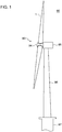
- FIG. 1 is a schematic configuration diagram of a wind turbine power generating apparatus according to an embodiment.
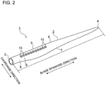
- FIG. 2 is a perspective view of a wind turbine blade according to an embodiment.
- a wind turbine power generating apparatus 90 includes a rotor 93 including at least one (e.g. three) wind turbine blades 1 and a hub 94.
- the wind turbine blades 1 are mounted to the hub 94 in a radial fashion, the rotor 93 rotates in response to wind received by the wind turbine blades 1, and a generator (not depicted) coupled to the rotor 93 generates electric power.
- the rotor 93 is supported by a nacelle 95 disposed on an upper part of a tower 96.
- the tower 96 is disposed to stand upright on a base structure 97 (e.g. foundation structure or floating structure) disposed onshore or offshore.
- vortex generators according to an embodiment is mounted to the wind turbine blades 1 of the wind turbine power generating apparatus 90.
- the wind turbine blade 1 includes a blade body 2 and a vortex generator 10 mounted to a surface (blade surface) of the blade body 2.
- the blade body 2 includes a blade root 3 to be attached to the hub 94 of the wind turbine power generating apparatus 90, a blade tip 4 positioned farthest from the hub 94, and an airfoil part 5 extending between the blade root 3 and the blade tip 4.
- the wind turbine blade 1 has a leading edge 6 and a trailing edge 7 from the blade root 3 to the blade tip 4. Further, an exterior shape of the wind turbine blade 1 is formed by a pressure surface 8 and a suction surface 9 disposed opposite to the pressure surface 8.
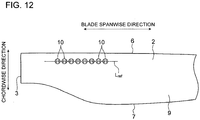
- a plurality of the vortex generators 10 is mounted to the suction surface 9 of the blade body 2. More specifically, the plurality of vortex generators 10 is mounted to the suction surface 9 of the blade body 2 in a blade spanwise direction.
- blade spanwise direction refers to a direction connecting the blade root 3 and the blade tip 4
- blade chordwise direction refers to a direction along a line (chord) connecting the leading edge 6 and the trailing edge 7 of the blade body 2.
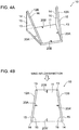
- FIGs. 3A and 4A are each a perspective view of the vortex generator 10 according to an embodiment
- FIGs. 3B and 4B are each a top view of the vortex generator 10 depicted in FIGs. 3A and 4A , respectively.
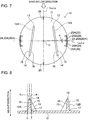
- FIGs. 5 to 7 are each a top view of the vortex generator 10 according to an embodiment.
- the vortex generator 10 includes a platform portion 11 to be fixed to a surface of the wind turbine blade 1 (more specifically, to a surface of the blade body 2) and at least one fin 12 disposed upright on the platform portion 11.
- the vortex generator 10 includes a pair (two in total) of fins 12 (12A, 12B) disposed so as to be adjacent to each other on the platform portion 11.
- the vortex generator 10 includes two pairs (four in total) of fins 12 (12A, 12B) disposed so as to be adjacent to each other on the platform portion 11.
- the platform portion 11 has a circular shape in a top view.
- the platform portion 11 has a trapezoidal shape in a top view.
- the platform portion 11 may have a shape other than a circle or a trapezoid.
- the platform portion 11 may have an oval shape as depicted in FIG. 6 , or may have a polygonal shape such as a rectangular shape, or another shape.
- the fin 12 has an airfoil shape.
- the fin 12 includes a leading edge 13 disposed on an upstream side with respect to the inflow direction of wind, a trailing edge 14 disposed on a downstream side with respect to the inflow direction of wind, a pressure surface 15 of the fin 12 facing toward upstream with respect to the inflow direction of wind, and a suction surface 16 of the fin 12 facing toward downstream with respect to the inflow direction of wind.
- the direction of a line connecting the leading edge 13 and the trailing edge 14 is the chordwise direction of the fin 12.
- the fin 12 is disposed inclined from the inflow direction of wind at a predetermined angle.
- each of the fins 12A, 12B is disposed so that a gap between the pair of fins 12A, 12B widens from upstream toward downstream with respect to the inflow direction of wind (i.e., from the side of the leading edge 6 toward the side of the trailing edge 7 of the wind turbine blade 1 (see FIG. 2 )).
- each of the fins 12A, 12B may be disposed so that a gap between the pair of fins 12A, 12B widens from downstream toward upstream with respect to the inflow direction of wind (i.e., from the side of the trailing edge 7 toward the side of the leading edge 6 of the wind turbine blade 1 (see FIG. 2 )).
- the vortex generator 10 mounted to the wind turbine blade 1 normally generates a longitudinal vortex on the side of the suction surface 16 of the fin 12 with a lift produced by the fin 12. Further, in response to a flow flowing into the fin 12, a longitudinal vortex is generated along an edge extending from the upstream-most position 13a toward the top portion 13b of the leading edge 13 of the fin 12.
- the longitudinal vortices generated by the fin 12 promote momentum exchange between outside and inside of a boundary layer on a surface of the wind turbine blade 1, in a height direction of the fin 12, at a downstream side of the vortex generator 10. Accordingly, the boundary layer on the surface of the wind turbine blade 1 reduces in thickness, and thereby trailing-edge separation of the wind turbine blade 1 is suppressed.
- the vortex generator 10 is disposed within a turbulent flow region of a wind flow along the suction surface 9, on the suction surface 9 of the blade body 2. As described above, the vortex generator 10 is disposed within a turbulent flow region of a wind flow along the suction surface 9, and thereby it is possible to suppress separation of a flow from the suction surface 9.
- the platform portion 11 has marks 20 which indicate orientation of the vortex generator, disposed on at least a pair of opposite positions in an outer edge region of the platform portion 11.
- the outer edge region of the platform portion 11 is a peripheral region of the contour of the platform portion in a planar view.
- the outer edge region of the platform portion 11 is, for instance, the peripheral region of the contour of the circular shape of the platform portion 11 in the example depicted in FIGs. 3A and 3B , and the peripheral region of the contour of the trapezoidal shape of the platform portion 11 in the example depicted in FIGs. 4A and 4B .
- a pair of opposite positions in the outer edge region of the platform portion 11 is a pair of positions facing each other across an inner region surrounded by the outer edge region, the positions being disposed within the outer edge region of the platform portion 11.
- the pair of the mark 20A and the mark 20A', and the pair of the mark 20B and the mark 20B' are each a pair of marks disposed on a pair of opposite positions in the outer edge region of the platform portion 11.
- the marks 20 disposed on a pair of opposite positions in the outer edge region of the platform portion 11 indirectly indicate the orientation of the fin 12 on the platform portion 11, and thus indicate the orientation of the vortex generator 10.
- wind normally flows into the wind turbine power generating apparatus 90 from the leading edge 6 toward the trailing edge 7 of the wind turbine blade 1.
- a reference direction that serves as a reference of a mounting direction of the vortex generator 10
- adjusting a mounting angle of the vortex generator 10 so that a direction indicated by the marks 20 of the vortex generator 10 forms a predetermined angle with the reference direction
- a suitable mounting direction of the vortex generator 10 on the wind turbine blade 1 can be determined on the basis of fluid analysis, for instance. Furthermore, a predetermined angle formed between the marks 20 of each vortex generator 10 and the reference direction on the wind turbine blade 1 can be determined on the basis of the reference direction defined for the wind turbine blade 1 and a suitable mounting direction determined in advance by fluid analysis or the like.
- the mark 20 may be a pair of marks formed on a pair of opposite positions, respectively, in the outer edge region of the platform portion 11 as depicted in FIGs. 3A to 4B , 6 , and 7 .
- the mark 20 may be provided as a mark 20 of a linear shape connecting marks 20A, 20A' at a pair of opposite positions in the outer edge region of the platform portion 11 as depicted in FIG. 5 .
- the platform portion 11 has a circular shape in a top view, and a line connecting a pair of opposite positions at which the marks 20 are formed passes through the center of the circular shape of the platform portion 11.
- a line L A connecting a pair of opposite positions at which the mark 20A and the mark 20A' are respectively provided passes through the center C of the circular shape of the platform portion 11.
- a line L B connecting a pair of opposite positions at which the mark 20B and the mark 20B' are respectively provided passes through the center C of the circular shape of the platform portion 11.
- a line e.g. L A or L B depicted in FIGs. 3B and 7
- a line that connects a pair of opposite positions at which the marks 20 are respectively formed on the platform portion 11 having a circular shape in a top view passing through the center C of the platform portion 11
- the pair of fins 12 (12A, 12B) disposed adjacent to each other on the platform portion 11 is oriented so that respective chordwise directions of the fins 12 intersect with each other.
- the pair of fins 12 (12A, 12B) is disposed on the platform portion 11 so that respective lines connecting the leading edge 13 and the trailing edge 14 of the fins 12A, 12B (lines L C1 , L C2 extending in respective chordwise directions) intersect with each other at an intersection I.
- the marks 20 disposed on the platform portion 11 include a reference mark (first reference mark) 24 and a reference mark (second reference mark) 26.
- the reference mark (first reference mark) 24 is the mark 20 disposed on a line which connects a pair of opposite positions (positions of a pair of marks 20 facing each other) passing through the center C of the circular shape of the platform portion 11, and which is orthogonal to a bisector L H (see FIG. 3B ) of an angle formed by chordwise directions of the two fins 12 (12A, 12B).
- the reference mark (second reference mark) 26 is the mark 20 disposed on a line which connects a pair of opposite positions (positions of a pair of marks 20 facing each other) passing through the center C of the circular shape of the platform portion 11, and which is parallel to a bisector L H of an angle formed by chordwise directions of the two fins 12 (12A, 12B).
- the line L A connecting a pair of opposite positions at which the mark 20A and the mark 20A' are respectively disposed is a line which passes through the center C of the circular shape of the platform portion 11, and which is orthogonal to the bisector L H of an angle formed by chordwise directions of the two fins 12 (12A, 12B) (an angle formed by lines L C1 , L C2 extending in respective chordwise directions).
- the mark 20A and the mark 20A' are each a reference mark (first reference mark) 24 disposed on the line L A .
- the line L B connecting a pair of opposite positions at which the mark 20B and the mark 20B' are respectively disposed is a line which passes through the center C of the circular shape of the platform portion 11, and which is parallel to the bisector L H of an angle formed by chordwise directions of the two fins 12 (12A, 12B) (an angle formed by lines L C1 , L C2 extending in respective chordwise directions). Furthermore, the mark 20B and the mark 20B' are each a reference mark (second reference mark) 26 disposed on the line L B .
- the platform portion 11 of a circular shape includes a reference mark (first reference mark) 24 and a reference mark (second reference mark) 26.
- the reference mark (first reference mark) 24 and the reference mark (second reference mark) 26 are disposed on lines (lines L A , L B in FIG. 3B ) passing through the center C of the circular shape of the platform portion 11 and extending orthogonal to each other, and thereby it is possible to match the position of the center C of the circular shape of the platform portion 11, which is an intersection of the lines L A , L B , with the mounting position of the vortex generator 10 with high accuracy. Accordingly, with the platform portion 11 having the reference mark (first reference mark) 24 and the reference mark (second reference mark) 26, it is possible to position the vortex generator 10 at the mounting position on the wind turbine blade 1 with high accuracy.
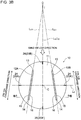
- the platform portion 11 includes the reference mark 24 and an angle-indicating mark 25 (25A, 25B).
- the reference mark 24 is a mark 20 formed along a reference line L R orthogonal to a bisector L H of an angle formed by chordwise directions of the two fins 12 (12A, 12B).
- the reference line L R is a line passing through the center C of the circular shape of the platform portion 11, and is the same line as the line L A connecting the pair of opposite positions at which the mark 20A and the mark 20A' are respectively disposed.
- the platform portion 11 has a circular shape and thus the reference mark 24 is equivalent to the first reference mark 24 described above, and thus is associated with the same reference numeral.
- the angle-indicating mark 25 is a mark 20 formed along a line forming a predetermined angle ⁇ with the reference line L R .
- the platform portion 11 includes a plurality of angle-indicating marks 25 disposed along respective lines which form different angles with the reference line L R (herein, angles about the center C of the circular shape of the platform portion 11).
- angle-indicating marks 25 corresponding to a plurality of determined angles ⁇ are formed on the platform portion 11.
- the plurality of angle-indicating marks 25 are disposed at regular angular intervals.
- the vortex generator 10 With the plurality of angle-indicating marks 25 formed on the platform portion 11 as described above, it is possible to mount the vortex generator 10 in a suitable mounting direction (at a mounting angle ⁇ ) with respect to the inflow direction of wind with high accuracy, by selecting the angle-indicating mark 25 forming a desired angle ⁇ with the reference line L R from among the plurality of angle-indicating marks 25, and aligning the angle-indicating mark 25 in the reference direction on the wind turbine blade 1.
- At least one of the plurality of angle-indicating marks 25 is different in length or thickness from the reference mark 24 and the other angle-indicating marks 25.
- the relatively-longer angle-indicating marks 25 and the relatively-shorter angle-indicating marks 25 may be disposed alternately.
- the marks 20 are recessed from the peripheral portion of the mark 20 on the platform portion 11.
- the marks 20 may be formed on the platform portion 11 as grooves recessed from the surface of the platform portion 11.
- the surface of the platform portion 11 of the vortex generator 10 becomes smooth as a result of another substance (e.g. sealant or putty) filling the recess corresponding to the marks 20 on the platform portion 11 during mounting of the vortex generator 10, or another substance (e.g. suspended matters in atmosphere) accumulating in the recess corresponding to the marks 20 during operation of the wind turbine power generating apparatus 90. Accordingly, during operation of the wind turbine power generating apparatus 90 with the vortex generator 10 mounted to the wind turbine blade 1, it is possible to reduce an influence from the marks 20 on a wind flow that the wind turbine blade 1 receives.
- another substance e.g. sealant or putty
- angle-indicating marks 25 may be disposed in the vicinity of the pair of reference marks (first reference marks) 24 (marks 20A, 20A') as depicted in FIG. 7 .
- the angle-indicating marks 25 may be disposed in the vicinity of the pair of reference marks (second reference marks) 26 (marks 20B, 20B').
- angle-indicating marks 25 may be disposed in the vicinity of either one mark 20 of the pair of opposite reference marks 24 (marks 20A, 20A'), or one mark 20 of the pair of opposite reference marks 26 (20B, 20B').
- the pressure surface 15 and the suction surface 16 of the fin 12 have a draft in the height direction based on the platform portion 11.
- FIG. 8 is a cross-sectional view of the vortex generator 10 taken along line VIII-VIII in FIG. 3B .
- the angles of the pressure surface 15 and the suction surface 16 are inclined by angular degrees ⁇ 1 , ⁇ 2 , respectively, from the height direction based on the platform portion 11 (a direction perpendicular to the platform portion 11), so that the thickness of the fin 12 reduces gradually toward a top portion 18 from a root portion 17 of the fin 12, at the trailing edge 14 of the fin 12.
- the pressure surface 15 and the suction surface 16 of the fin 12 have a draft in the height direction based on the platform portion 11, and thus the vortex generator 10 can be easily removed from a mold during production of the vortex generator 10 by molding.
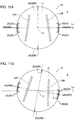
- FIGs. 9 to 12 are each a diagram for describing a method of mounting the vortex generator 10.
- vortex generator 10 is mounted to the suction surface 9 of the wind turbine blade 1 (blade body 2) in the following description as an example, the vortex generator 10 can be mounted to the pressure surface 8 of the wind turbine blade 1 by a similar method.
- the positions of reference points P 1 and P 2 are specified on the blade surface (suction surface 9) of the wind turbine blade 1.
- a reference point is a point for determining a reference direction which serves as a reference of a mounting direction of the vortex generator 10.
- the positions of the two reference points P 1 , P 2 on the blade surface of the wind turbine blade 1 are, for instance, specified on the basis of the mounting position of the vortex generator 10 determined in advance by fluid analysis or the like.
- a reference point can be, for instance, represented by coordinates (z, 1) in the blade spanwise direction and the chordwise direction on the blade surface of the wind turbine blade 1.
- the coordinates of the reference points P 1 and P 2 determined in advance are represented by P 1 (z 1 , l 1 ) and P 2 (z 2 , l 2 ), respectively.
- the positions corresponding to 1 coordinates (i.e., l 1 and l 2 ) of the reference points P 1 and P 2 can be specified on the blade surface by measuring the lengths from a blade spanwise directional line Ls along the blade spanwise direction on the blade surface.
- the blade spanwise directional line Ls is a line extending in the blade spanwise direction at a position between the leading edge 6 and the trailing edge 7 in the chord direction on the blade surface (suction surface 9).
- the line Ls can be drawn with reference to the position of a member (e.g. receptor) mounted to a specific position on the blade surface, for instance.
- the trailing edge 7 of the wind turbine blade 1 may be used as the blade longitudinal directional line Ls.
- the positions corresponding to z coordinates (i.e. z 1 and z 2 ) of the reference points P 1 and P 2 can be specified on the blade surface by measuring a distance from the blade root 3 with reference to the blade root 3 by laser measurement or the like.
- the vortex generator 10 is mounted to the wind turbine blade 1, so that the marks 20 representing orientation of the vortex generator 10 are disposed on the line L ref connecting the reference points P 1 and P 2 .
- the line L ref connecting the reference points P 1 and P 2 is a line representing a reference direction during mounting of the vortex generator 10 to the wind turbine blade 1.
- the line L ref may be displayed on the blade surface of the wind turbine blade 1 visually by using a tape or a pen, or by marking off, for instance.
- the marks 20 disposed on the line L ref during mounting of the vortex generator 10 may be the reference marks 24, or the angle-indicating marks 25.
- the vortex generator 10 having the reference marks 24 and the angle-indicating marks 25 is mounted to the wind turbine blade 1 so that the angle-indicating marks 25 are disposed on the line L ref .
- the vortex generator 10 is located on the surface of the wind turbine blade 1 in such a way that the pair of reference marks 24 is aligned along the line L ref .
- the vortex generator 10 is located in such a way that a reference point (e.g. the center C of the platform portion 11 having a circular shape) of the vortex generator 10 is at a predetermined mounting position in the blade spanwise direction.
- the mounting position of the vortex generator 10 in the blade spanwise direction may be determined in advance on the basis of fluid analysis or the like.
- the mounting position of the vortex generator 10 in the blade spanwise direction may be the same as the reference point P 1 or the reference point P 2 .
- FIG. 11A depicted is the vortex generator 10 located on the blade surface of the wind turbine blade 1 as described above.
- the mounting angle of the vortex generator 10 is adjusted by revolving the vortex generator 10 about the center C by a predetermined mounting angle ⁇ .
- the vortex generator 10 is rotated about the center C so that the angle-indicating marks 25, which form an angle ⁇ with the direction indicated by the reference marks 24, is aligned along the line L ref .
- the predetermined mounting angle ⁇ may be determined in advance on the basis of fluid analysis or the like.
- the mounting position and the mounting angle of the vortex generator 10 on the wind turbine blade 1 are adjusted as described above, and then the vortex generator 10 is fixed to the wind turbine blade 1.
- the vortex generator 10 may be fixed to the wind turbine blade 1 by using an adhesive agent or a double-sided adhesive tape.
- a plurality of the vortex generators 10 may be mounted to the wind turbine blade 1 with reference to the single line L ref drawn on the wind turbine blade 1. With the plurality of vortex generators 10 mounted to the wind turbine blade 1 with reference to the single line L ref as described above, it is possible to mount the wind turbine blade 1 efficiently to the vortex generator 10.
- the vortex generator 10 mounted to the wind turbine blade 1 in such a way that the marks 20 indicating orientation of the vortex generator 10 are disposed on the line L ref connecting the reference points P 1 and P 2 specified on the wind turbine blade 1, it is possible to mount the vortex generator 10 to the wind turbine blade 1 in a suitable mounting direction with respect to an inflow direction of wind.
- an expression of relative or absolute arrangement such as “in a direction”, “along a direction”, “parallel”, “orthogonal”, “centered”, “concentric” and “coaxial” shall not be construed as indicating only the arrangement in a strict literal sense, but also includes a state where the arrangement is relatively displaced by a tolerance, or by an angle or a distance whereby it is possible to achieve the same function.
- an expression of an equal state such as “same” “equal” and “uniform” shall not be construed as indicating only the state in which the feature is strictly equal, but also includes a state in which there is a tolerance or a difference that can still achieve the same function.
- an expression of a shape such as a rectangular shape or a cylindrical shape shall not be construed as only the geometrically strict shape, but also includes a shape with unevenness or chamfered corners within the range in which the same effect can be achieved.
Landscapes
- Engineering & Computer Science (AREA)
- Life Sciences & Earth Sciences (AREA)
- Sustainable Development (AREA)
- Sustainable Energy (AREA)
- Chemical & Material Sciences (AREA)
- Combustion & Propulsion (AREA)
- Mechanical Engineering (AREA)
- General Engineering & Computer Science (AREA)
- Physics & Mathematics (AREA)
- Fluid Mechanics (AREA)
- Wind Motors (AREA)
Applications Claiming Priority (2)
| Application Number | Priority Date | Filing Date | Title |
|---|---|---|---|
| JP2016035879A JP6148364B1 (ja) | 2016-02-26 | 2016-02-26 | 風車翼用ボルテックスジェネレータ、風車翼、風力発電装置、及びボルテックスジェネレータの取付方法 |
| EP16189464.7A EP3211220B1 (fr) | 2016-02-26 | 2016-09-19 | Générateur de vortex pour pale d'éolienne, pale d'éolienne, appareil de génération d'énergie éolienne et procédé de montage d'un générateur de vortex |
Related Parent Applications (2)
| Application Number | Title | Priority Date | Filing Date |
|---|---|---|---|
| EP16189464.7A Division EP3211220B1 (fr) | 2016-02-26 | 2016-09-19 | Générateur de vortex pour pale d'éolienne, pale d'éolienne, appareil de génération d'énergie éolienne et procédé de montage d'un générateur de vortex |
| EP16189464.7A Division-Into EP3211220B1 (fr) | 2016-02-26 | 2016-09-19 | Générateur de vortex pour pale d'éolienne, pale d'éolienne, appareil de génération d'énergie éolienne et procédé de montage d'un générateur de vortex |
Publications (2)
| Publication Number | Publication Date |
|---|---|
| EP3309388A1 true EP3309388A1 (fr) | 2018-04-18 |
| EP3309388B1 EP3309388B1 (fr) | 2019-06-26 |
Family
ID=56943425
Family Applications (2)
| Application Number | Title | Priority Date | Filing Date |
|---|---|---|---|
| EP17200830.2A Active EP3309388B1 (fr) | 2016-02-26 | 2016-09-19 | Générateur de tourbillon pour pale d'éolienne, pale d'éolienne, éolienne et procédé de montage d'un générateur de vortex |
| EP16189464.7A Active EP3211220B1 (fr) | 2016-02-26 | 2016-09-19 | Générateur de vortex pour pale d'éolienne, pale d'éolienne, appareil de génération d'énergie éolienne et procédé de montage d'un générateur de vortex |
Family Applications After (1)
| Application Number | Title | Priority Date | Filing Date |
|---|---|---|---|
| EP16189464.7A Active EP3211220B1 (fr) | 2016-02-26 | 2016-09-19 | Générateur de vortex pour pale d'éolienne, pale d'éolienne, appareil de génération d'énergie éolienne et procédé de montage d'un générateur de vortex |
Country Status (3)
| Country | Link |
|---|---|
| US (1) | US11319923B2 (fr) |
| EP (2) | EP3309388B1 (fr) |
| JP (1) | JP6148364B1 (fr) |
Cited By (2)
| Publication number | Priority date | Publication date | Assignee | Title |
|---|---|---|---|---|
| WO2020016351A1 (fr) | 2018-07-18 | 2020-01-23 | Wobben Properties Gmbh | Pale de rotor pour éolienne et éolienne |
| EP3954892A2 (fr) | 2020-07-21 | 2022-02-16 | Wobben Properties GmbH | Pale de rotor pour une éolienne, rotor pour une éolienne, construction et éolienne |
Families Citing this family (15)
| Publication number | Priority date | Publication date | Assignee | Title |
|---|---|---|---|---|
| JP6154050B1 (ja) | 2016-08-08 | 2017-06-28 | 三菱重工業株式会社 | 風車翼、風車ロータ及び風力発電装置並びにボルテックスジェネレータの取付方法 |
| DK3510273T3 (da) * | 2016-09-07 | 2024-07-29 | Lm Wind Power As | En hvirvelgeneratorindretning til en vindmøllevinge |
| JP6632553B2 (ja) | 2017-01-16 | 2020-01-22 | 三菱重工業株式会社 | ボルテックスジェネレータ及びその設置方法、並びに風車翼及び風力発電装置 |
| CN110691906B (zh) * | 2017-05-31 | 2022-07-01 | 西门子歌美飒可再生能源公司 | 具有定位标记的保护壳体 |
| CN107143470A (zh) * | 2017-07-07 | 2017-09-08 | 中航瑞德(北京)科技有限公司 | 风电叶片涡流增效组件及其安装方法 |
| US20190049480A1 (en) * | 2017-08-11 | 2019-02-14 | Olfree, Llc | Apparatus for detecting wind direction |
| JP6783212B2 (ja) | 2017-10-20 | 2020-11-11 | 三菱重工業株式会社 | 風車翼へのボルテックスジェネレータの配置位置決定方法、風車翼アセンブリの製造方法及び風車翼アセンブリ |
| JP6783211B2 (ja) | 2017-10-20 | 2020-11-11 | 三菱重工業株式会社 | 風車翼及び風車翼へのボルテックスジェネレータの配置決定方法 |
| CN108252871B (zh) * | 2018-02-06 | 2023-06-02 | 中科国风科技有限公司 | 一种风电叶片气动附件安装的定位装置及方法 |
| DE102018124084A1 (de) * | 2018-09-28 | 2020-04-02 | Wobben Properties Gmbh | Verfahren zum Betreiben einer Windenergieanlage, Windenergieanlage und Windpark |
| WO2021102171A1 (fr) * | 2019-11-21 | 2021-05-27 | University Of Washington | Régulation de tourbillons sur arête de nacelle de moteur et autres générateurs de tourbillons |
| JP7114679B2 (ja) * | 2020-11-27 | 2022-08-08 | 三菱重工業株式会社 | 風車翼用のボルテックスジェネレータ、風車翼及び風力発電装置 |
| CN115143027A (zh) * | 2021-03-31 | 2022-10-04 | 福建金风科技有限公司 | 涡流发生器以及风力发电机组 |
| KR102606803B1 (ko) * | 2021-12-03 | 2023-11-29 | 삼성중공업 주식회사 | 풍력 발전기용 블레이드 |
| KR102562255B1 (ko) * | 2021-12-03 | 2023-08-02 | 삼성중공업 주식회사 | 풍력 발전기용 블레이드 |
Citations (14)
| Publication number | Priority date | Publication date | Assignee | Title |
|---|---|---|---|---|
| WO2007140771A1 (fr) | 2006-06-09 | 2007-12-13 | Vestas Wind Systems A/S | Pale d'éolienne et éolienne à régulation de pas |
| US20120151769A1 (en) * | 2010-12-16 | 2012-06-21 | Inventus Holdings, Llc | Method for determining optimum vortex generator placement for maximum efficiency on a retrofitted wind turbine generator of unknown aerodynamic design |
| EP2484897A1 (fr) | 2011-02-04 | 2012-08-08 | LM Wind Power A/S | Générateur de tourbillons pour une éolienne doté d'une base comportant un retrait pour un adhésif |
| EP2484898A1 (fr) | 2011-02-04 | 2012-08-08 | LM Wind Power A/S | Dispositif générateur de vortex doté de sections biseautées pour une éolienne |
| EP2484896A1 (fr) | 2011-02-04 | 2012-08-08 | LM Wind Power A/S | Montage de dispositifs générateurs de vortex sur la pale d'une éolienne au moyen d'une plaque de montage |
| EP2484895A1 (fr) | 2011-02-04 | 2012-08-08 | LM Wind Power A/S | Paire d'aubes de générateur de tourbillons doté d'une base en forme de trapèze |
| EP2548800A1 (fr) | 2011-07-22 | 2013-01-23 | LM Wind Power A/S | Procédés pour rééquiper des générateurs de vortex sur une pale d'éolienne |
| EP2597300A1 (fr) | 2011-11-23 | 2013-05-29 | Siemens Aktiengesellschaft | Pale d'éolienne |
| US20140140856A1 (en) | 2011-07-22 | 2014-05-22 | Lm Wp Patent Holding A/S | Wind turbine blade comprising vortex generators |
| EP2799709A1 (fr) | 2013-05-02 | 2014-11-05 | General Electric Company | Système et procédé de fixation des générateurs de tourbillons pour éolienne |
| EP2801720A1 (fr) * | 2013-05-07 | 2014-11-12 | General Electric Company | Ensemble de modification de flux d'air pour une pale de rotor d'une éolienne |
| WO2015030573A1 (fr) | 2013-09-02 | 2015-03-05 | Corten Holding Bv | Générateur de vortex pour éolienne |
| WO2015053768A1 (fr) * | 2013-10-09 | 2015-04-16 | Siemens Aktiengesellschaft | Générateur de tourbillons du type articulé pour une réduction de tout excès de charge de vent sur une turbine éolienne |
| EP2975259A1 (fr) * | 2014-07-16 | 2016-01-20 | Envision Energy (Denmark) ApS | Unité génératrice de vortex pour une pale d'éolienne |
Family Cites Families (15)
| Publication number | Priority date | Publication date | Assignee | Title |
|---|---|---|---|---|
| US2690315A (en) * | 1952-10-06 | 1954-09-28 | Iron Fireman Mfg Co | Air vortex generator |
| US4175640A (en) * | 1975-03-31 | 1979-11-27 | Boeing Commercial Airplane Company | Vortex generators for internal mixing in a turbofan engine |
| US5117560A (en) * | 1990-06-06 | 1992-06-02 | Mary Nevins | Full circle protractor with detachable adjustable leg assembly for measuring angles |
| GB2265672B (en) | 1992-03-18 | 1995-11-22 | Advanced Wind Turbines Inc | Wind turbines |
| AU5618099A (en) | 1998-09-16 | 2000-04-03 | Lm Glasfiber A/S | Wind turbine blade with vortex generator |
| US6427948B1 (en) * | 2000-10-30 | 2002-08-06 | Michael Campbell | Controllable vortex generator |
| EP2031241A1 (fr) | 2007-08-29 | 2009-03-04 | Lm Glasfiber A/S | Pale de rotor pour éolienne dotée de moyens générateurs de barrière |
| US7966865B2 (en) | 2009-01-05 | 2011-06-28 | Michael Alfred Wilhelm Lenz | Method for balancing radical projections detached from a rotating assembly |
| US8047801B2 (en) | 2010-06-23 | 2011-11-01 | General Electric Company | Wind turbine blades with aerodynamic vortex elements |
| EP2548801A1 (fr) | 2011-07-22 | 2013-01-23 | LM Wind Power A/S | Pale d'éolienne comprenant des générateurs de vortex |
| DE102013201871C5 (de) | 2013-02-05 | 2018-09-06 | Senvion Gmbh | Vortexgenerator für ein Rotorblatt einer Windenergieanlage |
| US20140328688A1 (en) | 2013-05-03 | 2014-11-06 | General Electric Company | Rotor blade assembly having vortex generators for wind turbine |
| US9562513B2 (en) * | 2013-05-03 | 2017-02-07 | General Electric Company | Wind turbine rotor blade assembly with surface features |
| US20150010407A1 (en) | 2013-07-08 | 2015-01-08 | Alonso O. Zamora Rodriguez | Reduced noise vortex generator for wind turbine blade |
| US9624782B2 (en) | 2013-11-11 | 2017-04-18 | General Electric Company | Template for aligning surface features on a rotor blade |
-
2016
- 2016-02-26 JP JP2016035879A patent/JP6148364B1/ja active Active
- 2016-09-08 US US15/259,811 patent/US11319923B2/en active Active
- 2016-09-19 EP EP17200830.2A patent/EP3309388B1/fr active Active
- 2016-09-19 EP EP16189464.7A patent/EP3211220B1/fr active Active
Patent Citations (14)
| Publication number | Priority date | Publication date | Assignee | Title |
|---|---|---|---|---|
| WO2007140771A1 (fr) | 2006-06-09 | 2007-12-13 | Vestas Wind Systems A/S | Pale d'éolienne et éolienne à régulation de pas |
| US20120151769A1 (en) * | 2010-12-16 | 2012-06-21 | Inventus Holdings, Llc | Method for determining optimum vortex generator placement for maximum efficiency on a retrofitted wind turbine generator of unknown aerodynamic design |
| EP2484897A1 (fr) | 2011-02-04 | 2012-08-08 | LM Wind Power A/S | Générateur de tourbillons pour une éolienne doté d'une base comportant un retrait pour un adhésif |
| EP2484898A1 (fr) | 2011-02-04 | 2012-08-08 | LM Wind Power A/S | Dispositif générateur de vortex doté de sections biseautées pour une éolienne |
| EP2484896A1 (fr) | 2011-02-04 | 2012-08-08 | LM Wind Power A/S | Montage de dispositifs générateurs de vortex sur la pale d'une éolienne au moyen d'une plaque de montage |
| EP2484895A1 (fr) | 2011-02-04 | 2012-08-08 | LM Wind Power A/S | Paire d'aubes de générateur de tourbillons doté d'une base en forme de trapèze |
| EP2548800A1 (fr) | 2011-07-22 | 2013-01-23 | LM Wind Power A/S | Procédés pour rééquiper des générateurs de vortex sur une pale d'éolienne |
| US20140140856A1 (en) | 2011-07-22 | 2014-05-22 | Lm Wp Patent Holding A/S | Wind turbine blade comprising vortex generators |
| EP2597300A1 (fr) | 2011-11-23 | 2013-05-29 | Siemens Aktiengesellschaft | Pale d'éolienne |
| EP2799709A1 (fr) | 2013-05-02 | 2014-11-05 | General Electric Company | Système et procédé de fixation des générateurs de tourbillons pour éolienne |
| EP2801720A1 (fr) * | 2013-05-07 | 2014-11-12 | General Electric Company | Ensemble de modification de flux d'air pour une pale de rotor d'une éolienne |
| WO2015030573A1 (fr) | 2013-09-02 | 2015-03-05 | Corten Holding Bv | Générateur de vortex pour éolienne |
| WO2015053768A1 (fr) * | 2013-10-09 | 2015-04-16 | Siemens Aktiengesellschaft | Générateur de tourbillons du type articulé pour une réduction de tout excès de charge de vent sur une turbine éolienne |
| EP2975259A1 (fr) * | 2014-07-16 | 2016-01-20 | Envision Energy (Denmark) ApS | Unité génératrice de vortex pour une pale d'éolienne |
Cited By (5)
| Publication number | Priority date | Publication date | Assignee | Title |
|---|---|---|---|---|
| WO2020016351A1 (fr) | 2018-07-18 | 2020-01-23 | Wobben Properties Gmbh | Pale de rotor pour éolienne et éolienne |
| DE102018117398A1 (de) | 2018-07-18 | 2020-01-23 | Wobben Properties Gmbh | Rotorblatt für eine Windenergieanlage und Windenergieanlage |
| US11644007B2 (en) | 2018-07-18 | 2023-05-09 | Wobben Properties Gmbh | Rotor blade for a wind turbine and wind turbine |
| EP3954892A2 (fr) | 2020-07-21 | 2022-02-16 | Wobben Properties GmbH | Pale de rotor pour une éolienne, rotor pour une éolienne, construction et éolienne |
| US11703029B2 (en) | 2020-07-21 | 2023-07-18 | Wobben Properties Gmbh | Rotor blade for a wind power installation, rotor for a wind power installation, structure and wind power installation |
Also Published As
| Publication number | Publication date |
|---|---|
| EP3211220A1 (fr) | 2017-08-30 |
| US11319923B2 (en) | 2022-05-03 |
| US20170248116A1 (en) | 2017-08-31 |
| JP6148364B1 (ja) | 2017-06-14 |
| EP3211220B1 (fr) | 2018-06-13 |
| JP2017150447A (ja) | 2017-08-31 |
| EP3309388B1 (fr) | 2019-06-26 |
Similar Documents
| Publication | Publication Date | Title |
|---|---|---|
| EP3211220B1 (fr) | Générateur de vortex pour pale d'éolienne, pale d'éolienne, appareil de génération d'énergie éolienne et procédé de montage d'un générateur de vortex | |
| EP3282120B1 (fr) | Pale d'éolienne, rotor d'éolienne, appareil de génération d'énergie éolienne et procédé de montage d'un générateur de vortex | |
| US10760546B2 (en) | Mounting method and template for vortex generator | |
| EP3348824B1 (fr) | Générateur de tourbillon, son procédé d'installation, pale d'éolienne et appareil de production d'énergie éolienne | |
| US10697427B2 (en) | Vortex generator and wind turbine blade assembly | |
| US11149707B2 (en) | Wind turbine blade and method for determining arrangement of vortex generator on wind turbine blade | |
| EP3168459B1 (fr) | Générateur de tourbillon, pale d'éolienne et appareil de génération d'énergie éolienne | |
| EP3473850B1 (fr) | Procédé de détermination de la position d'agencement d'un générateur de vortex sur une pale de turbine éolienne, procédé de fabrication d'un ensemble de pales de turbine éolienne et ensemble de pales de turbine éolienne | |
| EP3431750B1 (fr) | Procédé de détermination de la position d'agencement d'un générateur de vortex sur une pale de turbine éolienne, procédé de fabrication d'un ensemble de pales de turbine éolienne et ensemble de pales de turbine éolienne | |
| Gustafson et al. | Aerodynamic measurements in a linear turbine blade passage with three-dimensional endwall contouring | |
| JP2021527774A (ja) | 風力タービンのロータブレードおよび風力タービン | |
| EP3916217A1 (fr) | Aube d'éolienne et procédé pour décider de l'agencement de générateurs de vortex pour une aube d'éolienne | |
| US12092072B2 (en) | Vortex generator for wind turbine blade, wind turbine blade and wind power generating apparatus, and method for manufacturing wind turbine blade | |
| CN109923301A (zh) | 风力涡轮机 |
Legal Events
| Date | Code | Title | Description |
|---|---|---|---|
| PUAI | Public reference made under article 153(3) epc to a published international application that has entered the european phase |
Free format text: ORIGINAL CODE: 0009012 |
|
| STAA | Information on the status of an ep patent application or granted ep patent |
Free format text: STATUS: THE APPLICATION HAS BEEN PUBLISHED |
|
| AC | Divisional application: reference to earlier application |
Ref document number: 3211220 Country of ref document: EP Kind code of ref document: P |
|
| AK | Designated contracting states |
Kind code of ref document: A1 Designated state(s): AL AT BE BG CH CY CZ DE DK EE ES FI FR GB GR HR HU IE IS IT LI LT LU LV MC MK MT NL NO PL PT RO RS SE SI SK SM TR |
|
| AX | Request for extension of the european patent |
Extension state: BA ME |
|
| STAA | Information on the status of an ep patent application or granted ep patent |
Free format text: STATUS: REQUEST FOR EXAMINATION WAS MADE |
|
| 17P | Request for examination filed |
Effective date: 20180831 |
|
| RBV | Designated contracting states (corrected) |
Designated state(s): AL AT BE BG CH CY CZ DE DK EE ES FI FR GB GR HR HU IE IS IT LI LT LU LV MC MK MT NL NO PL PT RO RS SE SI SK SM TR |
|
| GRAP | Despatch of communication of intention to grant a patent |
Free format text: ORIGINAL CODE: EPIDOSNIGR1 |
|
| STAA | Information on the status of an ep patent application or granted ep patent |
Free format text: STATUS: GRANT OF PATENT IS INTENDED |
|
| RIC1 | Information provided on ipc code assigned before grant |
Ipc: F03D 1/06 20060101AFI20181204BHEP |
|
| INTG | Intention to grant announced |
Effective date: 20190103 |
|
| GRAS | Grant fee paid |
Free format text: ORIGINAL CODE: EPIDOSNIGR3 |
|
| GRAA | (expected) grant |
Free format text: ORIGINAL CODE: 0009210 |
|
| STAA | Information on the status of an ep patent application or granted ep patent |
Free format text: STATUS: THE PATENT HAS BEEN GRANTED |
|
| AC | Divisional application: reference to earlier application |
Ref document number: 3211220 Country of ref document: EP Kind code of ref document: P |
|
| AK | Designated contracting states |
Kind code of ref document: B1 Designated state(s): AL AT BE BG CH CY CZ DE DK EE ES FI FR GB GR HR HU IE IS IT LI LT LU LV MC MK MT NL NO PL PT RO RS SE SI SK SM TR |
|
| REG | Reference to a national code |
Ref country code: GB Ref legal event code: FG4D |
|
| REG | Reference to a national code |
Ref country code: CH Ref legal event code: EP |
|
| REG | Reference to a national code |
Ref country code: AT Ref legal event code: REF Ref document number: 1148568 Country of ref document: AT Kind code of ref document: T Effective date: 20190715 |
|
| REG | Reference to a national code |
Ref country code: DE Ref legal event code: R096 Ref document number: 602016016088 Country of ref document: DE |
|
| REG | Reference to a national code |
Ref country code: IE Ref legal event code: FG4D |
|
| REG | Reference to a national code |
Ref country code: NL Ref legal event code: MP Effective date: 20190626 |
|
| PG25 | Lapsed in a contracting state [announced via postgrant information from national office to epo] |
Ref country code: FI Free format text: LAPSE BECAUSE OF FAILURE TO SUBMIT A TRANSLATION OF THE DESCRIPTION OR TO PAY THE FEE WITHIN THE PRESCRIBED TIME-LIMIT Effective date: 20190626 Ref country code: NO Free format text: LAPSE BECAUSE OF FAILURE TO SUBMIT A TRANSLATION OF THE DESCRIPTION OR TO PAY THE FEE WITHIN THE PRESCRIBED TIME-LIMIT Effective date: 20190926 Ref country code: HR Free format text: LAPSE BECAUSE OF FAILURE TO SUBMIT A TRANSLATION OF THE DESCRIPTION OR TO PAY THE FEE WITHIN THE PRESCRIBED TIME-LIMIT Effective date: 20190626 Ref country code: LT Free format text: LAPSE BECAUSE OF FAILURE TO SUBMIT A TRANSLATION OF THE DESCRIPTION OR TO PAY THE FEE WITHIN THE PRESCRIBED TIME-LIMIT Effective date: 20190626 Ref country code: AL Free format text: LAPSE BECAUSE OF FAILURE TO SUBMIT A TRANSLATION OF THE DESCRIPTION OR TO PAY THE FEE WITHIN THE PRESCRIBED TIME-LIMIT Effective date: 20190626 Ref country code: SE Free format text: LAPSE BECAUSE OF FAILURE TO SUBMIT A TRANSLATION OF THE DESCRIPTION OR TO PAY THE FEE WITHIN THE PRESCRIBED TIME-LIMIT Effective date: 20190626 |
|
| REG | Reference to a national code |
Ref country code: LT Ref legal event code: MG4D |
|
| PG25 | Lapsed in a contracting state [announced via postgrant information from national office to epo] |
Ref country code: GR Free format text: LAPSE BECAUSE OF FAILURE TO SUBMIT A TRANSLATION OF THE DESCRIPTION OR TO PAY THE FEE WITHIN THE PRESCRIBED TIME-LIMIT Effective date: 20190927 Ref country code: LV Free format text: LAPSE BECAUSE OF FAILURE TO SUBMIT A TRANSLATION OF THE DESCRIPTION OR TO PAY THE FEE WITHIN THE PRESCRIBED TIME-LIMIT Effective date: 20190626 Ref country code: RS Free format text: LAPSE BECAUSE OF FAILURE TO SUBMIT A TRANSLATION OF THE DESCRIPTION OR TO PAY THE FEE WITHIN THE PRESCRIBED TIME-LIMIT Effective date: 20190626 Ref country code: BG Free format text: LAPSE BECAUSE OF FAILURE TO SUBMIT A TRANSLATION OF THE DESCRIPTION OR TO PAY THE FEE WITHIN THE PRESCRIBED TIME-LIMIT Effective date: 20190926 |
|
| REG | Reference to a national code |
Ref country code: AT Ref legal event code: MK05 Ref document number: 1148568 Country of ref document: AT Kind code of ref document: T Effective date: 20190626 |
|
| PG25 | Lapsed in a contracting state [announced via postgrant information from national office to epo] |
Ref country code: RO Free format text: LAPSE BECAUSE OF FAILURE TO SUBMIT A TRANSLATION OF THE DESCRIPTION OR TO PAY THE FEE WITHIN THE PRESCRIBED TIME-LIMIT Effective date: 20190626 Ref country code: SK Free format text: LAPSE BECAUSE OF FAILURE TO SUBMIT A TRANSLATION OF THE DESCRIPTION OR TO PAY THE FEE WITHIN THE PRESCRIBED TIME-LIMIT Effective date: 20190626 Ref country code: CZ Free format text: LAPSE BECAUSE OF FAILURE TO SUBMIT A TRANSLATION OF THE DESCRIPTION OR TO PAY THE FEE WITHIN THE PRESCRIBED TIME-LIMIT Effective date: 20190626 Ref country code: PT Free format text: LAPSE BECAUSE OF FAILURE TO SUBMIT A TRANSLATION OF THE DESCRIPTION OR TO PAY THE FEE WITHIN THE PRESCRIBED TIME-LIMIT Effective date: 20191028 Ref country code: NL Free format text: LAPSE BECAUSE OF FAILURE TO SUBMIT A TRANSLATION OF THE DESCRIPTION OR TO PAY THE FEE WITHIN THE PRESCRIBED TIME-LIMIT Effective date: 20190626 Ref country code: EE Free format text: LAPSE BECAUSE OF FAILURE TO SUBMIT A TRANSLATION OF THE DESCRIPTION OR TO PAY THE FEE WITHIN THE PRESCRIBED TIME-LIMIT Effective date: 20190626 Ref country code: AT Free format text: LAPSE BECAUSE OF FAILURE TO SUBMIT A TRANSLATION OF THE DESCRIPTION OR TO PAY THE FEE WITHIN THE PRESCRIBED TIME-LIMIT Effective date: 20190626 |
|
| PG25 | Lapsed in a contracting state [announced via postgrant information from national office to epo] |
Ref country code: IT Free format text: LAPSE BECAUSE OF FAILURE TO SUBMIT A TRANSLATION OF THE DESCRIPTION OR TO PAY THE FEE WITHIN THE PRESCRIBED TIME-LIMIT Effective date: 20190626 Ref country code: ES Free format text: LAPSE BECAUSE OF FAILURE TO SUBMIT A TRANSLATION OF THE DESCRIPTION OR TO PAY THE FEE WITHIN THE PRESCRIBED TIME-LIMIT Effective date: 20190626 Ref country code: SM Free format text: LAPSE BECAUSE OF FAILURE TO SUBMIT A TRANSLATION OF THE DESCRIPTION OR TO PAY THE FEE WITHIN THE PRESCRIBED TIME-LIMIT Effective date: 20190626 Ref country code: IS Free format text: LAPSE BECAUSE OF FAILURE TO SUBMIT A TRANSLATION OF THE DESCRIPTION OR TO PAY THE FEE WITHIN THE PRESCRIBED TIME-LIMIT Effective date: 20191026 |
|
| PG25 | Lapsed in a contracting state [announced via postgrant information from national office to epo] |
Ref country code: TR Free format text: LAPSE BECAUSE OF FAILURE TO SUBMIT A TRANSLATION OF THE DESCRIPTION OR TO PAY THE FEE WITHIN THE PRESCRIBED TIME-LIMIT Effective date: 20190626 |
|
| PG25 | Lapsed in a contracting state [announced via postgrant information from national office to epo] |
Ref country code: PL Free format text: LAPSE BECAUSE OF FAILURE TO SUBMIT A TRANSLATION OF THE DESCRIPTION OR TO PAY THE FEE WITHIN THE PRESCRIBED TIME-LIMIT Effective date: 20190626 Ref country code: DK Free format text: LAPSE BECAUSE OF FAILURE TO SUBMIT A TRANSLATION OF THE DESCRIPTION OR TO PAY THE FEE WITHIN THE PRESCRIBED TIME-LIMIT Effective date: 20190626 |
|
| PG25 | Lapsed in a contracting state [announced via postgrant information from national office to epo] |
Ref country code: MC Free format text: LAPSE BECAUSE OF FAILURE TO SUBMIT A TRANSLATION OF THE DESCRIPTION OR TO PAY THE FEE WITHIN THE PRESCRIBED TIME-LIMIT Effective date: 20190626 Ref country code: IS Free format text: LAPSE BECAUSE OF FAILURE TO SUBMIT A TRANSLATION OF THE DESCRIPTION OR TO PAY THE FEE WITHIN THE PRESCRIBED TIME-LIMIT Effective date: 20200320 |
|
| REG | Reference to a national code |
Ref country code: CH Ref legal event code: PL |
|
| REG | Reference to a national code |
Ref country code: DE Ref legal event code: R097 Ref document number: 602016016088 Country of ref document: DE |
|
| PLBE | No opposition filed within time limit |
Free format text: ORIGINAL CODE: 0009261 |
|
| STAA | Information on the status of an ep patent application or granted ep patent |
Free format text: STATUS: NO OPPOSITION FILED WITHIN TIME LIMIT |
|
| PG2D | Information on lapse in contracting state deleted |
Ref country code: IS |
|
| PG25 | Lapsed in a contracting state [announced via postgrant information from national office to epo] |
Ref country code: CH Free format text: LAPSE BECAUSE OF NON-PAYMENT OF DUE FEES Effective date: 20190930 Ref country code: LU Free format text: LAPSE BECAUSE OF NON-PAYMENT OF DUE FEES Effective date: 20190919 Ref country code: IE Free format text: LAPSE BECAUSE OF NON-PAYMENT OF DUE FEES Effective date: 20190919 Ref country code: LI Free format text: LAPSE BECAUSE OF NON-PAYMENT OF DUE FEES Effective date: 20190930 |
|
| 26N | No opposition filed |
Effective date: 20200603 |
|
| REG | Reference to a national code |
Ref country code: BE Ref legal event code: MM Effective date: 20190930 |
|
| PG25 | Lapsed in a contracting state [announced via postgrant information from national office to epo] |
Ref country code: SI Free format text: LAPSE BECAUSE OF FAILURE TO SUBMIT A TRANSLATION OF THE DESCRIPTION OR TO PAY THE FEE WITHIN THE PRESCRIBED TIME-LIMIT Effective date: 20190626 Ref country code: BE Free format text: LAPSE BECAUSE OF NON-PAYMENT OF DUE FEES Effective date: 20190930 |
|
| PG25 | Lapsed in a contracting state [announced via postgrant information from national office to epo] |
Ref country code: CY Free format text: LAPSE BECAUSE OF FAILURE TO SUBMIT A TRANSLATION OF THE DESCRIPTION OR TO PAY THE FEE WITHIN THE PRESCRIBED TIME-LIMIT Effective date: 20190626 |
|
| PG25 | Lapsed in a contracting state [announced via postgrant information from national office to epo] |
Ref country code: HU Free format text: LAPSE BECAUSE OF FAILURE TO SUBMIT A TRANSLATION OF THE DESCRIPTION OR TO PAY THE FEE WITHIN THE PRESCRIBED TIME-LIMIT; INVALID AB INITIO Effective date: 20160919 Ref country code: MT Free format text: LAPSE BECAUSE OF FAILURE TO SUBMIT A TRANSLATION OF THE DESCRIPTION OR TO PAY THE FEE WITHIN THE PRESCRIBED TIME-LIMIT Effective date: 20190626 |
|
| PG25 | Lapsed in a contracting state [announced via postgrant information from national office to epo] |
Ref country code: MK Free format text: LAPSE BECAUSE OF FAILURE TO SUBMIT A TRANSLATION OF THE DESCRIPTION OR TO PAY THE FEE WITHIN THE PRESCRIBED TIME-LIMIT Effective date: 20190626 |
|
| PGFP | Annual fee paid to national office [announced via postgrant information from national office to epo] |
Ref country code: GB Payment date: 20230727 Year of fee payment: 8 |
|
| PGFP | Annual fee paid to national office [announced via postgrant information from national office to epo] |
Ref country code: FR Payment date: 20230808 Year of fee payment: 8 Ref country code: DE Payment date: 20230802 Year of fee payment: 8 |