EP3308935A1 - Weight compensated molding machine - Google Patents
Weight compensated molding machine Download PDFInfo
- Publication number
- EP3308935A1 EP3308935A1 EP17199407.2A EP17199407A EP3308935A1 EP 3308935 A1 EP3308935 A1 EP 3308935A1 EP 17199407 A EP17199407 A EP 17199407A EP 3308935 A1 EP3308935 A1 EP 3308935A1
- Authority
- EP
- European Patent Office
- Prior art keywords
- wing
- pad
- linear way
- spring
- suspended component
- Prior art date
- Legal status (The legal status is an assumption and is not a legal conclusion. Google has not performed a legal analysis and makes no representation as to the accuracy of the status listed.)
- Withdrawn
Links
- 238000000465 moulding Methods 0.000 title claims abstract description 25
- 230000000712 assembly Effects 0.000 description 4
- 238000000429 assembly Methods 0.000 description 4
- 230000005484 gravity Effects 0.000 description 4
- 238000007665 sagging Methods 0.000 description 3
- 238000001746 injection moulding Methods 0.000 description 2
- 230000007246 mechanism Effects 0.000 description 2
- 238000000034 method Methods 0.000 description 2
- 238000012986 modification Methods 0.000 description 2
- 230000004048 modification Effects 0.000 description 2
- 229910001369 Brass Inorganic materials 0.000 description 1
- 230000009286 beneficial effect Effects 0.000 description 1
- 239000010951 brass Substances 0.000 description 1
- 230000000295 complement effect Effects 0.000 description 1
- 238000007373 indentation Methods 0.000 description 1
- 238000009434 installation Methods 0.000 description 1
- 230000000717 retained effect Effects 0.000 description 1
- 238000006467 substitution reaction Methods 0.000 description 1
Images


Classifications
-
- B—PERFORMING OPERATIONS; TRANSPORTING
- B29—WORKING OF PLASTICS; WORKING OF SUBSTANCES IN A PLASTIC STATE IN GENERAL
- B29C—SHAPING OR JOINING OF PLASTICS; SHAPING OF MATERIAL IN A PLASTIC STATE, NOT OTHERWISE PROVIDED FOR; AFTER-TREATMENT OF THE SHAPED PRODUCTS, e.g. REPAIRING
- B29C45/00—Injection moulding, i.e. forcing the required volume of moulding material through a nozzle into a closed mould; Apparatus therefor
- B29C45/17—Component parts, details or accessories; Auxiliary operations
- B29C45/26—Moulds
- B29C45/2602—Mould construction elements
-
- B—PERFORMING OPERATIONS; TRANSPORTING
- B29—WORKING OF PLASTICS; WORKING OF SUBSTANCES IN A PLASTIC STATE IN GENERAL
- B29C—SHAPING OR JOINING OF PLASTICS; SHAPING OF MATERIAL IN A PLASTIC STATE, NOT OTHERWISE PROVIDED FOR; AFTER-TREATMENT OF THE SHAPED PRODUCTS, e.g. REPAIRING
- B29C45/00—Injection moulding, i.e. forcing the required volume of moulding material through a nozzle into a closed mould; Apparatus therefor
- B29C45/17—Component parts, details or accessories; Auxiliary operations
- B29C45/40—Removing or ejecting moulded articles
- B29C45/4005—Ejector constructions; Ejector operating mechanisms
- B29C2045/4052—Ejector boxes
-
- B—PERFORMING OPERATIONS; TRANSPORTING
- B29—WORKING OF PLASTICS; WORKING OF SUBSTANCES IN A PLASTIC STATE IN GENERAL
- B29C—SHAPING OR JOINING OF PLASTICS; SHAPING OF MATERIAL IN A PLASTIC STATE, NOT OTHERWISE PROVIDED FOR; AFTER-TREATMENT OF THE SHAPED PRODUCTS, e.g. REPAIRING
- B29C45/00—Injection moulding, i.e. forcing the required volume of moulding material through a nozzle into a closed mould; Apparatus therefor
- B29C45/17—Component parts, details or accessories; Auxiliary operations
- B29C45/1742—Mounting of moulds; Mould supports
-
- B—PERFORMING OPERATIONS; TRANSPORTING
- B29—WORKING OF PLASTICS; WORKING OF SUBSTANCES IN A PLASTIC STATE IN GENERAL
- B29C—SHAPING OR JOINING OF PLASTICS; SHAPING OF MATERIAL IN A PLASTIC STATE, NOT OTHERWISE PROVIDED FOR; AFTER-TREATMENT OF THE SHAPED PRODUCTS, e.g. REPAIRING
- B29C45/00—Injection moulding, i.e. forcing the required volume of moulding material through a nozzle into a closed mould; Apparatus therefor
- B29C45/17—Component parts, details or accessories; Auxiliary operations
- B29C45/1761—Means for guiding movable mould supports or injection units on the machine base or frame; Machine bases or frames
-
- B—PERFORMING OPERATIONS; TRANSPORTING
- B29—WORKING OF PLASTICS; WORKING OF SUBSTANCES IN A PLASTIC STATE IN GENERAL
- B29C—SHAPING OR JOINING OF PLASTICS; SHAPING OF MATERIAL IN A PLASTIC STATE, NOT OTHERWISE PROVIDED FOR; AFTER-TREATMENT OF THE SHAPED PRODUCTS, e.g. REPAIRING
- B29C45/00—Injection moulding, i.e. forcing the required volume of moulding material through a nozzle into a closed mould; Apparatus therefor
- B29C45/17—Component parts, details or accessories; Auxiliary operations
- B29C45/26—Moulds
- B29C45/2673—Moulds with exchangeable mould parts, e.g. cassette moulds
- B29C45/2675—Mounting of exchangeable mould inserts
Definitions
- Non-Limiting embodiments disclosed herein generally relate to mold assemblies for a molding machine and to a molding machine.
- Molding machines are heavy industrial machines: the replaceable mold assemblies for these machines can weigh upwards of fifty tonnes. Even with strong supports, the weight of moving parts of a molding machine can cause misalignments due to sagging. These misalignments can increase the wear on both the molding machine and the mold in the machine, as well as negatively affecting the quality of the produced parts.
- Wings are provided on mold components and linear ways are provided below these wings.
- a pad rides on each linear way below each wing.
- a force generator such as a spring, is disposed between each wing and underlying pad. In this way the weight of the suspended component is borne, at least in part, by the linear ways so that the weight on components that might otherwise sag is lessened.
- a mold assembly for use in a molding machine comprising: an ejector box having a plurality of guides, said ejector box defining at least one ejector box linear way; a cassette having at least one cassette plate extending within said ejector box and supported on said guides, each cassette plate for supporting a mold piece, each cassette plate having at least one cassette plate support member extending over one said ejector box linear way; at least one pad riding on each said ejector box linear way such that there is a pad below each cassette plate support member; a force generator disposed between said cassette plate support member and said pad below said cassette plate support member.
- a molding machine comprising: a moveable platen; an ejector box attached to said moveable platen, said ejector box having a plurality of guides, said ejector box having at least one ejector box linear way; a cassette having at least one cassette plate extending within said ejector box and supported on said guides, each cassette plate supporting a mold piece, each cassette plate having at least one cassette plate support extending over one said ejector box linear way; at least one pad riding on each said ejector box linear way such that there is a pad below each cassette plate support; a force generator disposed between said each cassette plate support and said pad below said each cassette plate support.
- a molding machine comprising: a bed having a first linear way and a second linear way; a moveable platen moveably supported on said bed; a fixed platen fixed to said bed; an ejector box affixed to said moveable platen, said ejector box having a first wing and an opposed second wing; a first pad riding on said first linear way and a second pad riding on said second linear way; an outer end of said first wing disposed above said first pad and an outer end of said second wing disposed above said second pad; at least one spring disposed between said outer end of first wing and said first pad and at least one spring disposed between said outer end of said second wing and said second pad; one of said outer end of said first wing and said first pad providing a key and another of said outer end of said first wing and said first pad providing a keyway so that said first wing may move upwardly away from first pad and said first pad is constrained to move along said first linear way with said first wing;
- a molding machine comprising: a suspended component having a first wing and an opposed second wing projecting outwardly from opposed sides of said suspended component; a first linear way provided below said first wing; a second linear way provided below said second wing; a first pad slidably received on said first linear way below said first wing; a second pad slidably received on said second linear way below said second wing; a force generator disposed between said first wing and said first pad; and a force generator disposed between said second wing and said second pad.
- an injection molding machine 10 has a fixed platen 12 which is fixed to a bed 14 and a moveable platen 16 that rides on rails 18 extending along the top of the bed 14. Tie bars 15 (omitted from FIG. 1 for clarity but seen in FIG. 2 ) provide further support for the moveable platen.
- a hot mold half 20 is mounted to the fixed platen 12.
- the hot mold half 20 has a mold cavity 22 communicating with a sprue 24. As is conventional, the sprue may terminate a runner (not shown) extending from a screw injector (not shown).
- the hot mold half has leader pin guides 26.
- a mold assembly namely, an ejector box 30 with a cassette 50, is mounted to the moving platen 16.
- the ejector box has a rear plate 32, front plate 34, and outer walls 38.
- Leader pins 40 project from the front plate 34 of the ejector box toward the leader pin guides 26 of the hot mold half 20 and rearwardly into bearings of cavities in the walls 38 of the ejector box.
- Guides 42 extend from the rear plate 32 of the ejector box 30 into bearings 43 in its front plate 34.
- the cassette 50 is slidably mounted to guides 42 within the ejector box 30 by bearings 51.
- the cassette has a first plate 52 which holds the inner mold piece 62 of a mold stack 60, a second plate 54 which holds the outer mold piece 64 of the mold stack, and a third plate 56 which holds the stripper sleeve 66 of the mold stack 60.
- the rear plate 32 of the ejector box 30 slidably supports a locking plate (not shown) that is repositionable between a locking position and an unlocking position.
- a locking plate (not shown) that is repositionable between a locking position and an unlocking position.
- the locking plate When the locking plate is in the locking position the cassette 50 is held in a molding position within the ejector box 30.
- the plates of the cassette 50 are repositionable within the ejector box 30 for performing one or more mold function such as, for example, ejection of the molded article from the mold stack 60.
- Motion of the plates may be driven by an ejector actuator (not shown) that is associated with the molding machine 10.
- an ejector actuator (not shown) that is associated with the molding machine 10.
- the mold machine 10 is provided with mechanisms to compensate for the weight of the cassette and of the ejector box. More specifically, turning to FIG. 2 , ejector box 30 has a window 90a, 90b in each of its side walls 38a, 38b. A linear way 94a, 94b defines the bottom of each window. Plate 56 of the cassette has a pair of wings 96a, 96b. An outer end 98a of wing 96a extends over linear way 94a and an outer end 98b of wing 96b extends over linear way 94b.
- a pad 100a is disposed between the outer end 98a of wing 96a and the linear way 94a and a spring 102a is captured between the outer end of the wing and the pad 100a.
- a pad 100b is disposed between the outer end 98b of wing 96b and the linear way 94b and a spring 102b is captured between the outer end of the wing and the pad 100b.
- the springs 102a, 102b act directly against the force of gravity on plate 56 of the cassette and therefore act to reduce the apparent weight of plate 56 on guides 42.
- Like mechanisms are provided for other plates 52, 54 of the cassette.
- Wings 110a, 110b project from the side walls 38a, 38b of ejector box 30.
- An outer end 112a of wing 110a extends over a linear way 114a of bed rail 14a and an outer end 112b of wing 110b extends over linear way 114b of bed rail 14b.
- a pad 120a is disposed between the outer end 112a of wing 110a and the linear way 114a and a spring 122a is captured between the outer end of the wing 110a and the pad 120a.
- a pad 120b is disposed between the outer end 112b of wing 110b and the linear way 114b and a spring 122b is captured between the outer end of the wing and the pad 120b.
- a brass wear pad 124a, 124b lines the top of respective linear ways 114a, 114b.
- the springs 122a, 122b act directly against the force of gravity on the ejector box 30 and therefore act to reduce the apparent cantilevered torque of the ejector box on moveable platen 16.
- FIG. 3 to 5 Another example ejector box is illustrated in FIG. 3 to 5 .
- ejector box 130 has a rear plate 132 and front plate 134 bridged by guides 142 on which a cassette 150 is supported.
- Leader pins 140 project from the front plate 134.
- the cassette has plates 152-1, 152-2, 152-3, and 152-4, each of which holds one piece of multiple mold stacks 160 (two of which are illustrated).
- the rear plate 132 of the ejector box 130 slidably supports a locking plate 166 for side-to-side movement between a locking position and an unlocking position.
- the locking plate has a set of locking members 168 and a control bar 167 which is used to position the locking plate.
- the locking members 168 When the locking members 168 are in the locking position the locking members 168 cooperate with complementary structure on the plates 152-1 to 152-4 to hold the cassette 150 in a molding position within the ejector box 130.
- the plates of the cassette 150 are repositionable within the ejector box 130 for performing one or more mold function such as, for example, ejection of the molded articles from the mold stacks 160.
- Motion of the plates may be driven by an ejector actuator (not shown) that is associated with the molding machine 10 via ejector rods 172-1, 172-2, 172-3 that push against the plates 152-1 to 152-4.
- an ejector actuator (not shown) that is associated with the molding machine 10 via ejector rods 172-1, 172-2, 172-3 that push against the plates 152-1 to 152-4.
- Ejector box 130 has a window 190a, 190b in each of its side walls 138a, 138b.
- a linear way 194a, 194b defines the bottom of each window.
- Plate 152-1 of the cassette has a pair of wings 196-1. An outer end of each wing 196-1 extends over one of linear ways 194a and 194b.
- a pad 200-1 is disposed between the outer end of each wing 196-1 and the underlying linear way 194a or 194b.
- each wing 196-1 defines an annular cavity 199 which is open at either end and receives a shouldered annular spring container 204-1 in which a spring 202 is contained.
- Pad 200-1 abuts the base of the spring container such that the spring 202 is captured between the upper shoulders 206 of the spring container and the pad 200-1.
- the pad has upstanding arms 212f, 212r which extend along the front 214f and rear 214r surfaces of the outer end of wing 196-1.
- the wing surfaces 214f and 214r act as a key and the front and rear surfaces of the upstanding arms 212f and 212r of the pad act as a keyway so that the pad 200-1 is constrained to move along the linear way 194a with the wing 196-1 yet the wing is free to move up independently of the pad.
- cassette plates 152-2, 152-3, 152-4 have wings 196-2, 196-3, 196-4 with annular cavities 199 receiving spring containers 204-2, 204-3, 204-4.
- Springs 202 are also captured between these spring containers and respective pads 200-2, 200-3, 200-4.
- the springs 202 act directly against the force of gravity on the plates 152-1, 152-2, 152-3, 152-4 of the cassette and therefore act to reduce the apparent weight of the plates on the guides 142.
- the spring constant (stiffness) of the springs 202 and the height of the lower shoulders 207 of the spring containers 204-1, 204-2, 204-3, 204-4 may be selected based on the weight of the plates 152-1, 152-2, 152-3, 152-4 so that the weight of the plates is balanced as desired.
- a 208 washer is placed on top of each spring containers 204-1, 204-2, 204-3, 204-4 and a screw 210 is inserted through each spring container and threaded into a threaded bore of each pad 200-1 to 200-4.
- These screws hold the spring assemblies together as the plates 152-1, 152-2, 152-3, 152-4 are set in place on the linear way 194a. Once the plates are in place, the screws 210 and washers 208 are removed.
- wings 310a, 310b project from the side walls 138a, 138b of ejector box 130.
- An outer end 312 of wing 310a extends over a linear way (not shown) of a bed rail (not shown) and an outer end of wing 310b extends over a linear way (not shown) of a bed rail (not shown).
- a pad 320a is disposed between the outer end 312 of wing 310a and the linear way below it and a spring 322 is captured between the outer end of the wing 310a and the pad 320a.
- a pad 320b is disposed between the outer end 312b of wing 310b and the linear way below it and a spring is captured between the outer end of the wing and the pad 320b.
- a wear pad 314 is attached to the bottom of each pad 320a.
- the outer end 312 of wing 310a has two open ended shouldered annular cavities 324-1, 324-2.
- a spring 322 is disposed in each such cavity and trapped between the shoulders 326 of the cavity and the underlying pad 320a.
- a stroke limiting pin 328 with a threaded tip extends through the upper opening 325 of each annular cavity and is threaded to threaded bore 330 in the pad 320a such that, with pad 320a abutting the outer end 312 of wing 310a, the head of the pin is at a stand-off from the top surface of the wing.
- Each pin acts as a key and the upper opening 325 through which it extends acts as a keyway to permit the wing 310a to lift away from the underlying pad (up to the point where the upper surface of the wing abuts the head of the pin) but constraining the pad to move along the underlying linear way with the wing.
- the outer end of wing 310b is identically configured.
- the springs 322 act directly against the force of gravity on the ejector box 130 and therefore act to reduce the apparent cantilevered torque of the ejector box when mounted to a moveable platen.
- the force applied by the springs may be selected by choosing the spring constant and the depth of shoulders 326 of the spring cavities.
- FIG. 7 shows two spring cavities
- a greater, or lesser, number of spring cavities and springs could be provided.
- the outer end of wing 410a has three open ended shouldered annular cavities 424-1, 424-2, 424-3 with a spring 322 is disposed in each such cavity and trapped between the shoulders 326 of the cavity and the underlying pad 320a.
- each plate 552 of the ejector box has a wing half 596a projecting therefrom to which a second wing half 596b attaches by means of screws 545 and dowels 547 to form an open ended wing.
- the wing receives a shouldered annular spring container 504 such that the lower shoulder 507 of the spring container abuts the bottom of the wing.
- a spring 502 is contained within the spring container.
- a pad 500 abuts the base of the spring container such that the spring 502 is captured between the upper shoulder 506 of the spring container and the pad.
- the pad has a central well 549 sized to receive and closely fit to the lower shoulder 507 of the spring container.
- the pad 500 also has an upwardly projecting peg 553 which assists in locating the spring 502.
- a wear plate 514 is attached by screws 555 to the pad 500.
- the lower shoulder 507 of the spring container acts as a key and the central well 549 of the pad 500 as a keyway such that, in operation, the pad is constrained to move with the wing along the linear way 594 yet the wing is free to move vertically relative to the pad.
- FIGs. 10 and 11 show another embodiment of the spring assemblies for the ejector box.
- springs 722 are captured between an outer end 712 of wing 710 and pad 720. More specifically, the outer end 712 of the wing is an inverted cup-shape with internal walls 757 forming spring locating wells. These match spring locating wells formed by walls 759 of the pad 720 so that the wells of the wing end and pad form spring containers.
- the outer end 712 of wing 710 has two bores 724-1, 724-2.
- a stroke limiting pin 728 with a threaded tip extends through each bore and is threaded to a threaded bore 730 in the pad 720 such that, with pad 720 abutting the outer end 712 of wing 710, the head of the pin 728 is at a stand-off from the top surface of the wing.
- Each pin 728 acts as a key and the bore through which it extends acts as a keyway to permit the wing 710 to lift away from the underlying pad (up to the point where the upper surface of the wing abuts the head of the pin) but constraining the pad to move along an underlying linear way.
- the top surface of the pad 720 has two indentations 761 which receive C-clips 763.
- a wear pad 714 is attached to the bottom of pad 720 by screws 755 which pass through the wear pad and pad 720 and are retained by the C-clips.
Landscapes
- Engineering & Computer Science (AREA)
- Manufacturing & Machinery (AREA)
- Mechanical Engineering (AREA)
- Moulds For Moulding Plastics Or The Like (AREA)
- Injection Moulding Of Plastics Or The Like (AREA)
Abstract
Description
- Non-Limiting embodiments disclosed herein generally relate to mold assemblies for a molding machine and to a molding machine.
- Molding machines are heavy industrial machines: the replaceable mold assemblies for these machines can weigh upwards of fifty tonnes. Even with strong supports, the weight of moving parts of a molding machine can cause misalignments due to sagging. These misalignments can increase the wear on both the molding machine and the mold in the machine, as well as negatively affecting the quality of the produced parts.
- An approach to compensate for sagging is described in
U.S. Patent No. 7,753,668 to Glaesener et al. issued July 13, 2010 . In Glaesener, the output of a level sensor is used by a controller to generate a control signal which varies the cylinder pressure of an anti-tilt actuator in order to compensate for sagging. - Wings are provided on mold components and linear ways are provided below these wings. A pad rides on each linear way below each wing. A force generator, such as a spring, is disposed between each wing and underlying pad. In this way the weight of the suspended component is borne, at least in part, by the linear ways so that the weight on components that might otherwise sag is lessened.
- In an aspect, there is provided a mold assembly for use in a molding machine comprising: an ejector box having a plurality of guides, said ejector box defining at least one ejector box linear way; a cassette having at least one cassette plate extending within said ejector box and supported on said guides, each cassette plate for supporting a mold piece, each cassette plate having at least one cassette plate support member extending over one said ejector box linear way; at least one pad riding on each said ejector box linear way such that there is a pad below each cassette plate support member; a force generator disposed between said cassette plate support member and said pad below said cassette plate support member.
- In another aspect, there is provided a molding machine comprising: a moveable platen; an ejector box attached to said moveable platen, said ejector box having a plurality of guides, said ejector box having at least one ejector box linear way; a cassette having at least one cassette plate extending within said ejector box and supported on said guides, each cassette plate supporting a mold piece, each cassette plate having at least one cassette plate support extending over one said ejector box linear way; at least one pad riding on each said ejector box linear way such that there is a pad below each cassette plate support; a force generator disposed between said each cassette plate support and said pad below said each cassette plate support.
- In a further aspect, there is provided a molding machine comprising: a bed having a first linear way and a second linear way; a moveable platen moveably supported on said bed; a fixed platen fixed to said bed; an ejector box affixed to said moveable platen, said ejector box having a first wing and an opposed second wing; a first pad riding on said first linear way and a second pad riding on said second linear way; an outer end of said first wing disposed above said first pad and an outer end of said second wing disposed above said second pad; at least one spring disposed between said outer end of first wing and said first pad and at least one spring disposed between said outer end of said second wing and said second pad; one of said outer end of said first wing and said first pad providing a key and another of said outer end of said first wing and said first pad providing a keyway so that said first wing may move upwardly away from first pad and said first pad is constrained to move along said first linear way with said first wing; one of said outer end of said second wing and said second pad providing a key and another of said outer end of said second wing and said second pad providing a keyway so that said second wing may move upwardly away from second pad and said second pad is constrained to move along said second linear way with said second wing.
- In yet a further aspect, there is provided a molding machine comprising: a suspended component having a first wing and an opposed second wing projecting outwardly from opposed sides of said suspended component; a first linear way provided below said first wing; a second linear way provided below said second wing; a first pad slidably received on said first linear way below said first wing; a second pad slidably received on said second linear way below said second wing; a force generator disposed between said first wing and said first pad; and a force generator disposed between said second wing and said second pad.
- These and other aspects and features of non-limiting embodiments will now become apparent to those skilled in the art upon review of the following description of specific non-limiting embodiments in conjunction with the accompanying drawings.
- The non-limiting embodiments will be more fully appreciated by reference to the accompanying drawings, in which:
-
FIG. 1 is a schematic, partially sectioned, longitudinal view of an injection molding machine, -
FIG. 2 is a schematic cross-sectional view along the lines II-II ofFIG. 1 , -
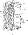
FIG. 3 is a perspective view of an ejector box and cassette in accordance with another embodiment which may be used in the molding machine ofFIG. 1 , -
FIG. 4 is a perspective view of a portion of the ejector box ofFIG. 3 , -
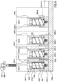
FIG. 5 is a perspective view of the cassette ofFIG. 3 , -
FIG. 6 is a fragmentary cross-sectional view along the lines VI-VI ofFIG. 3 , -
FIG. 7 is a fragmentary cross-sectional view along the lines VII-VII ofFIG. 3 , -
FIG. 8 is a fragmentary cross-sectional view in accordance with another embodiment, -
FIG. 9 is a fragmentary exploded view in accordance with another embodiment, -
FIG. 10 is an exploded view of a portion of an ejector box in accordance with another embodiment, and -
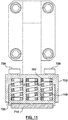
FIG. 11 is a front view of the portion of the ejector box ofFIG. 10 . - The drawings are not necessarily to scale and may be illustrated by phantom lines, diagrammatic representations and fragmentary views. In certain instances, details that are not necessary for an understanding of the embodiments or that render other details difficult to perceive may have been omitted.
- Reference will now be made in detail to various non-limiting embodiment(s) of a mold assembly for use in a molding machine. It should be understood that other non-limiting embodiment(s), modifications and equivalents will be evident to one of ordinary skill in the art in view of the non-limiting embodiment(s) disclosed herein and that these variants should be considered to be within scope of the appended claims.
- Furthermore, it will be recognized by one of ordinary skill in the art that certain structural and operational details of the non-limiting embodiment(s) discussed hereafter may be modified or omitted (i.e. non-essential) altogether. In other instances, well known methods, procedures, and components have not been described in detail.
- Turning to
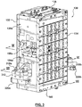
FIG. 1 , aninjection molding machine 10 has afixed platen 12 which is fixed to abed 14 and amoveable platen 16 that rides onrails 18 extending along the top of thebed 14. Tie bars 15 (omitted fromFIG. 1 for clarity but seen inFIG. 2 ) provide further support for the moveable platen. Ahot mold half 20 is mounted to the fixedplaten 12. Thehot mold half 20 has amold cavity 22 communicating with asprue 24. As is conventional, the sprue may terminate a runner (not shown) extending from a screw injector (not shown). The hot mold half hasleader pin guides 26. - A mold assembly, namely, an
ejector box 30 with acassette 50, is mounted to the movingplaten 16. (The distance between thebed 14 and theejector box 30 andhot mold 20 has been increased inFIG. 1 for clarity of the drawing.) The ejector box has arear plate 32,front plate 34, andouter walls 38. Leader pins 40 project from thefront plate 34 of the ejector box toward theleader pin guides 26 of thehot mold half 20 and rearwardly into bearings of cavities in thewalls 38 of the ejector box.Guides 42 extend from therear plate 32 of theejector box 30 intobearings 43 in itsfront plate 34. Thecassette 50 is slidably mounted toguides 42 within theejector box 30 bybearings 51. The cassette has afirst plate 52 which holds theinner mold piece 62 of amold stack 60, asecond plate 54 which holds theouter mold piece 64 of the mold stack, and athird plate 56 which holds thestripper sleeve 66 of themold stack 60. Therear plate 32 of theejector box 30 slidably supports a locking plate (not shown) that is repositionable between a locking position and an unlocking position. When the locking plate is in the locking position thecassette 50 is held in a molding position within theejector box 30. In the unlocking position the plates of thecassette 50 are repositionable within theejector box 30 for performing one or more mold function such as, for example, ejection of the molded article from themold stack 60. Motion of the plates may be driven by an ejector actuator (not shown) that is associated with themolding machine 10. A more detailed description of the foregoing structure may be referenced in Applicant'sPCT application WO 2011/063499(A1) to Halter et al., published on June 3, 2011 . - To address misalignments during operation, the
mold machine 10 is provided with mechanisms to compensate for the weight of the cassette and of the ejector box. More specifically, turning toFIG. 2 ,ejector box 30 has awindow side walls linear way Plate 56 of the cassette has a pair ofwings outer end 98a ofwing 96a extends overlinear way 94a and anouter end 98b ofwing 96b extends overlinear way 94b. Apad 100a is disposed between theouter end 98a ofwing 96a and thelinear way 94a and aspring 102a is captured between the outer end of the wing and thepad 100a. Similarly, apad 100b is disposed between theouter end 98b ofwing 96b and thelinear way 94b and aspring 102b is captured between the outer end of the wing and thepad 100b. Thesprings plate 56 of the cassette and therefore act to reduce the apparent weight ofplate 56 onguides 42. Like mechanisms are provided forother plates -
Wings side walls ejector box 30. Anouter end 112a ofwing 110a extends over alinear way 114a ofbed rail 14a and anouter end 112b ofwing 110b extends overlinear way 114b ofbed rail 14b. Apad 120a is disposed between theouter end 112a ofwing 110a and thelinear way 114a and aspring 122a is captured between the outer end of thewing 110a and thepad 120a. Similarly, apad 120b is disposed between theouter end 112b ofwing 110b and thelinear way 114b and aspring 122b is captured between the outer end of the wing and thepad 120b. Abrass wear pad linear ways springs ejector box 30 and therefore act to reduce the apparent cantilevered torque of the ejector box onmoveable platen 16. - Another example ejector box is illustrated in
FIG. 3 to 5 . Turning to these figures,ejector box 130 has arear plate 132 andfront plate 134 bridged byguides 142 on which acassette 150 is supported. Leader pins 140 project from thefront plate 134. The cassette has plates 152-1, 152-2, 152-3, and 152-4, each of which holds one piece of multiple mold stacks 160 (two of which are illustrated). - The
rear plate 132 of theejector box 130 slidably supports alocking plate 166 for side-to-side movement between a locking position and an unlocking position. The locking plate has a set of lockingmembers 168 and acontrol bar 167 which is used to position the locking plate. When the lockingmembers 168 are in the locking position the lockingmembers 168 cooperate with complementary structure on the plates 152-1 to 152-4 to hold thecassette 150 in a molding position within theejector box 130. In the unlocking position (not shown) the plates of thecassette 150 are repositionable within theejector box 130 for performing one or more mold function such as, for example, ejection of the molded articles from the mold stacks 160. Motion of the plates may be driven by an ejector actuator (not shown) that is associated with themolding machine 10 via ejector rods 172-1, 172-2, 172-3 that push against the plates 152-1 to 152-4. Again, a more detailed description of the foregoing structure may be referenced in Applicant'sPCT application WO 2011/063499(A1) to Halter et al., published on June 3, 2011 . -
Ejector box 130 has awindow side walls linear way linear ways linear way - Turning to
FIG. 6 , each wing 196-1 defines anannular cavity 199 which is open at either end and receives a shouldered annular spring container 204-1 in which aspring 202 is contained. Pad 200-1 abuts the base of the spring container such that thespring 202 is captured between theupper shoulders 206 of the spring container and the pad 200-1. The pad hasupstanding arms upstanding arms linear way 194a with the wing 196-1 yet the wing is free to move up independently of the pad. - Similarly, cassette plates 152-2, 152-3, 152-4 have wings 196-2, 196-3, 196-4 with
annular cavities 199 receiving spring containers 204-2, 204-3, 204-4.Springs 202 are also captured between these spring containers and respective pads 200-2, 200-3, 200-4. - The
springs 202 act directly against the force of gravity on the plates 152-1, 152-2, 152-3, 152-4 of the cassette and therefore act to reduce the apparent weight of the plates on theguides 142. Notably, the spring constant (stiffness) of thesprings 202 and the height of thelower shoulders 207 of the spring containers 204-1, 204-2, 204-3, 204-4 may be selected based on the weight of the plates 152-1, 152-2, 152-3, 152-4 so that the weight of the plates is balanced as desired. - To facilitate installation, a 208 washer is placed on top of each spring containers 204-1, 204-2, 204-3, 204-4 and a
screw 210 is inserted through each spring container and threaded into a threaded bore of each pad 200-1 to 200-4. These screws hold the spring assemblies together as the plates 152-1, 152-2, 152-3, 152-4 are set in place on thelinear way 194a. Once the plates are in place, thescrews 210 andwashers 208 are removed. - Turning to
FIGs. 3 ,4 , and7 wings side walls ejector box 130. - An
outer end 312 ofwing 310a extends over a linear way (not shown) of a bed rail (not shown) and an outer end ofwing 310b extends over a linear way (not shown) of a bed rail (not shown). Apad 320a is disposed between theouter end 312 ofwing 310a and the linear way below it and aspring 322 is captured between the outer end of thewing 310a and thepad 320a. Similarly, apad 320b is disposed between the outer end 312b ofwing 310b and the linear way below it and a spring is captured between the outer end of the wing and thepad 320b. - With specific reference to
FIG. 7 , awear pad 314 is attached to the bottom of eachpad 320a. Theouter end 312 ofwing 310a has two open ended shouldered annular cavities 324-1, 324-2. Aspring 322 is disposed in each such cavity and trapped between theshoulders 326 of the cavity and theunderlying pad 320a. Astroke limiting pin 328 with a threaded tip extends through theupper opening 325 of each annular cavity and is threaded to threadedbore 330 in thepad 320a such that, withpad 320a abutting theouter end 312 ofwing 310a, the head of the pin is at a stand-off from the top surface of the wing. Each pin acts as a key and theupper opening 325 through which it extends acts as a keyway to permit thewing 310a to lift away from the underlying pad (up to the point where the upper surface of the wing abuts the head of the pin) but constraining the pad to move along the underlying linear way with the wing. The outer end ofwing 310b is identically configured. - The
springs 322 act directly against the force of gravity on theejector box 130 and therefore act to reduce the apparent cantilevered torque of the ejector box when mounted to a moveable platen. Again, the force applied by the springs may be selected by choosing the spring constant and the depth ofshoulders 326 of the spring cavities. - Although
FIG. 7 shows two spring cavities, a greater, or lesser, number of spring cavities and springs could be provided. For example, with reference toFIG. 8 , wherein like parts to those ofFIG. 7 have been given like reference numerals, the outer end ofwing 410a has three open ended shouldered annular cavities 424-1, 424-2, 424-3 with aspring 322 is disposed in each such cavity and trapped between theshoulders 326 of the cavity and theunderlying pad 320a. - Turning to
FIG. 9 , in another embodiment of a spring assembly for the ejector plates, eachplate 552 of the ejector box has awing half 596a projecting therefrom to which asecond wing half 596b attaches by means ofscrews 545 and dowels 547 to form an open ended wing. The wing receives a shoulderedannular spring container 504 such that thelower shoulder 507 of the spring container abuts the bottom of the wing. Aspring 502 is contained within the spring container. Apad 500 abuts the base of the spring container such that thespring 502 is captured between theupper shoulder 506 of the spring container and the pad. The pad has acentral well 549 sized to receive and closely fit to thelower shoulder 507 of the spring container. Thepad 500 also has an upwardly projectingpeg 553 which assists in locating thespring 502. Awear plate 514 is attached byscrews 555 to thepad 500. Thelower shoulder 507 of the spring container acts as a key and the central well 549 of thepad 500 as a keyway such that, in operation, the pad is constrained to move with the wing along thelinear way 594 yet the wing is free to move vertically relative to the pad. -
FIGs. 10 and11 show another embodiment of the spring assemblies for the ejector box. Turning toFIGs. 10 and11 , springs 722 are captured between anouter end 712 ofwing 710 andpad 720. More specifically, theouter end 712 of the wing is an inverted cup-shape withinternal walls 757 forming spring locating wells. These match spring locating wells formed bywalls 759 of thepad 720 so that the wells of the wing end and pad form spring containers. Theouter end 712 ofwing 710 has two bores 724-1, 724-2. Astroke limiting pin 728 with a threaded tip extends through each bore and is threaded to a threadedbore 730 in thepad 720 such that, withpad 720 abutting theouter end 712 ofwing 710, the head of thepin 728 is at a stand-off from the top surface of the wing. Eachpin 728 acts as a key and the bore through which it extends acts as a keyway to permit thewing 710 to lift away from the underlying pad (up to the point where the upper surface of the wing abuts the head of the pin) but constraining the pad to move along an underlying linear way. The top surface of thepad 720 has twoindentations 761 which receive C-clips 763. Awear pad 714 is attached to the bottom ofpad 720 byscrews 755 which pass through the wear pad andpad 720 and are retained by the C-clips. - It would be possible to replace the springs with another force generator to apply an upward force on the wings of the cassette plates and the ejector box. For example, it would be possible to utilize air cylinders in place of the springs. With this substitution, the magnitude of the upward force could be adjusted by adjusting the air pressure in the cylinders.
- The approach described to compensate for the weight of cassette plates and an ejector box can be used with other suspended components and in different types of mold machines.
- It is noted that the foregoing has outlined some of the more pertinent non-limiting embodiments. It will be clear to those skilled in the art that modifications to the disclosed non-embodiment(s) can be effected without departing from the spirit and scope thereof. As such, the described non-limiting embodiment(s) ought to be considered to be merely illustrative of some of the more prominent features and applications. Other beneficial results can be realized by applying the non-limiting embodiments in a different manner or modifying them in ways known to those familiar with the art. This includes the mixing and matching of features, elements and/or functions between various non-limiting embodiment(s) is expressly contemplated herein so that one of ordinary skill in the art would appreciate from this disclosure that features, elements and/or functions of one embodiment may be incorporated into another embodiment as skill in the art would appreciate from this disclosure that features, elements and/or functions of one embodiment may be incorporated into another embodiment as appropriate, unless described otherwise, above. The present invention further pertains to:
- 1. A mold assembly for use in a molding machine (10) comprising:
- an ejector box (30, 130) having a plurality of guides (42, 142), said ejector box defining at least one ejector box linear way (94a, 94b; 194a, 194b);
- a cassette (50, 150) having at least one cassette plate (52, 54, 56; 152-1, 152-2, 152-3, 152-4) extending within said ejector box and supported on said guides, each cassette plate for supporting a mold piece (62, 64, 66), each cassette plate having at least one cassette plate support member (96a, 96b; 196-1, 196-2, 196-3, 196-4) extending over one said ejector box linear way;
- at least one pad (100a, 100b; 200-1, 200-2, 200-3, 200-4) riding on each said ejector box linear way such that there is a pad below each cassette plate support member; and
- a force generator (102a, 102b; 202) disposed between said cassette plate support member and said pad below said cassette plate support member.
- 2. The mold assembly of
item 1 wherein said at least one ejector box linear way comprises a first ejector box linear way (94a; 194a) at a first side of said ejector box and a second ejector box linear way (94b; 194b) at a second side of said ejector box and wherein said at least one cassette plate support member comprises a pair of wings (96a, 96b; 196-1, 196-2, 196-3, 196-4) projecting from opposed sides of said each cassette plate. - 3. The mold assembly of item 2 wherein each said force generator is a spring (102a, 102b; 202).
- 4. The mold assembly of item 3 wherein an outer end of each wing of said pair of wings defines a spring cavity (199) for receiving one said spring.
- 5. The mold assembly of item 4 wherein one of said outer end of each wing (96a, 96b; 196-1, 196-2, 196-3, 196-4) and each pad (100a, 100b; 200-1. 200-2, 200-3, 200-4) below said outer end of each wing defines a key (214f, 214r) and another of said outer end of each wing and said pad below said outer end of each wing defines a keyway (212f, 212r) such that any given wing is free to move toward and away from a given pad below said given wing and said given pad is constrained to move along said linear way with said given wing.
- 6. The mold assembly of item 5 wherein said key comprises outer faces (214f, 214r) of said outer end (98a, 98b) of said wing and said keyway comprises upstanding arms (212f, 212r) of each said pad.
- 7. The mold assembly of item 2 wherein said ejector box has a pair of ejector box wings (110a, 110b; 310a, 310b; 410a) with at least one spring cavity (324-1, 324-2, 424-1) at an outer end of each of said ejector box wings.
- 8. A molding machine (10) comprising:
- a bed having a first linear way (14a) and a second linear way (14b);
- a moveable platen (16) moveably supported on said bed;
- a fixed platen (12) fixed to said bed;
- an ejector box (30) affixed to said moveable platen, said ejector box having a first wing (110a) and an opposed second wing (110b);
- a first pad (120a) riding on said first linear way and a second pad (120b) riding on said second linear way;
- an outer end of said first wing (110a) disposed above said first pad (120a) and an outer end of said second wing (110b) disposed above said second pad (120b);
- at least one spring (122a) disposed between said outer end of said first wing and said first pad and at least one spring (122b) disposed between said outer end of said second wing and said second pad;
- one of said outer end of said first wing and said first pad providing a key and another of said outer end of said first wing and said first pad providing a keyway so that said first wing may move upwardly away from first pad and said first pad is constrained to move along said first linear way with said first wing;
- one of said outer end of said second wing and said second pad providing a key and another of said outer end of said second wing and said second pad providing a keyway so that said second wing may move upwardly away from second pad and said second pad is constrained to move along said second linear way with said second wing.
- 9. The molding machine of item 8 wherein said outer end of said first wing comprises at least one first wing cavity, each of said at least one first wing cavity for containing one spring and wherein said outer end of said second wing comprises at least one second wing cavity, each of said at least one second wing cavity for containing one spring (122a, 122b).
- 10. The molding machine of item 9 wherein one said keyway comprises a bore in said first pad and one said key comprises a pin (201) extending through said first wing cavity and into said bore of said first pad.
Claims (5)
- A molding machine (10) comprising:a suspended component (30) having a first wing (110a) and an opposed second wing (11Ob) projecting outwardly from opposed sides of said suspended component;a first linear way (14a) provided below said first wing;a second linear way (14b) provided below said second wing;a first pad (120a) slidably received on said first linear way below said first wing;a second pad (120b) slidably received on said second linear way below said second wing;a force generator (122a) disposed between said first wing and said first pad; anda force generator (122b) disposed between said second wing and said second pad.
- The molding machine of claim 1 wherein:said suspended component is a first suspended component and said first suspended component has a first suspended component first linear way (94a) and a first suspended component second linear way (94b) and further comprising:a second suspended component (56) having a second suspended component first wing (96a) and an opposed second suspended component second wing (96b) projecting outwardly from opposed sides of said second suspended component over respective ones of said first suspended component first linear way (94a) and said first suspended component second linear way (94b);a third pad (100a) slidably received on said first suspended component first linear way below said second suspended component first wing;a fourth pad (100b) slidably received on said first suspended component second linear way below said second suspended component second wing;a force generator (102a) disposed between said second suspended component first wing and said third pad; anda force generator (102b) disposed between said second suspended component second wing and said fourth pad.
- The molding machine of claim 1 wherein one of said first wing and said first pad defines a key and another of said first wing and said first pad defines a keyway such that said first wing is free to move toward and away from said first pad and said first pad is constrained to move along said first linear way with said first wing.
- The molding machine of claim 2 wherein each said force generator is a spring (102a, 102b).
- The mold machine of claim 4 wherein said first wing defines a spring cavity for receiving one said spring and wherein said second wing defines a spring cavity for receiving one said spring.
Applications Claiming Priority (2)
| Application Number | Priority Date | Filing Date | Title |
|---|---|---|---|
| US201361812439P | 2013-04-16 | 2013-04-16 | |
| EP14785705.6A EP2986433B1 (en) | 2013-04-16 | 2014-03-03 | Weight compensated molding machine |
Related Parent Applications (2)
| Application Number | Title | Priority Date | Filing Date |
|---|---|---|---|
| EP14785705.6A Division EP2986433B1 (en) | 2013-04-16 | 2014-03-03 | Weight compensated molding machine |
| EP14785705.6A Division-Into EP2986433B1 (en) | 2013-04-16 | 2014-03-03 | Weight compensated molding machine |
Publications (1)
| Publication Number | Publication Date |
|---|---|
| EP3308935A1 true EP3308935A1 (en) | 2018-04-18 |
Family
ID=51730632
Family Applications (2)
| Application Number | Title | Priority Date | Filing Date |
|---|---|---|---|
| EP17199407.2A Withdrawn EP3308935A1 (en) | 2013-04-16 | 2014-03-03 | Weight compensated molding machine |
| EP14785705.6A Not-in-force EP2986433B1 (en) | 2013-04-16 | 2014-03-03 | Weight compensated molding machine |
Family Applications After (1)
| Application Number | Title | Priority Date | Filing Date |
|---|---|---|---|
| EP14785705.6A Not-in-force EP2986433B1 (en) | 2013-04-16 | 2014-03-03 | Weight compensated molding machine |
Country Status (5)
| Country | Link |
|---|---|
| US (1) | US9931775B2 (en) |
| EP (2) | EP3308935A1 (en) |
| CN (2) | CN105121123B (en) |
| CA (1) | CA2907706C (en) |
| WO (1) | WO2014169379A1 (en) |
Families Citing this family (2)
| Publication number | Priority date | Publication date | Assignee | Title |
|---|---|---|---|---|
| CN106273291A (en) * | 2015-05-20 | 2017-01-04 | 鸿富锦精密工业(深圳)有限公司 | Shutter device and there is the mould of this shutter device |
| CN105818338B (en) * | 2016-05-05 | 2018-06-05 | 罗杰 | A kind of shoemaking sole injection mold |
Citations (6)
| Publication number | Priority date | Publication date | Assignee | Title |
|---|---|---|---|---|
| DE1931432A1 (en) * | 1969-06-20 | 1971-01-07 | Fahr Bucher Gmbh | Injection-moulding machine for plastics |
| DE3029597A1 (en) * | 1980-08-05 | 1982-03-04 | Karl 7298 Loßburg Hehl | Injection-moulding machine closing unit - has two slide surfaces at right angles on each guide shoe |
| US5297952A (en) * | 1991-09-12 | 1994-03-29 | Engel Maschinenbau Gesellschaft M.B.H. | Injection molding machine with articulated closure |
| JP2004330449A (en) * | 2003-04-30 | 2004-11-25 | Toshiba Mach Co Ltd | Moving die support device and mold clamping device |
| US7753668B2 (en) | 2007-01-24 | 2010-07-13 | Husky Injection Molding Systems Ltd. | Platen assembly, molding system and method for platen orientation and alignment |
| WO2011063499A1 (en) | 2009-11-30 | 2011-06-03 | Husky Injection Molding Systems Ltd. | A molded article transfer device with shuttling movement |
Family Cites Families (9)
| Publication number | Priority date | Publication date | Assignee | Title |
|---|---|---|---|---|
| JPH084911B2 (en) * | 1989-01-30 | 1996-01-24 | 宇部興産株式会社 | Mold clamping device for molding machines |
| US5249951A (en) * | 1991-10-25 | 1993-10-05 | Engel Maschinenbau Gesellschaft M.B.H. | Injection molding machine having tiltable mounting plates |
| US5440646A (en) * | 1994-02-18 | 1995-08-08 | United Technologies Automotive, Inc. | Molded housing with integral acoustic chamber and anti-rattle printed circuit board supports |
| JP2954858B2 (en) * | 1994-09-16 | 1999-09-27 | 日精エー・エス・ビー機械株式会社 | Injection stretch blow molding apparatus and method |
| US7128564B2 (en) * | 2003-12-11 | 2006-10-31 | Husky Injection Molding Systems Ltd. | Simplified in-mold article handling system and a method for handling molded articles |
| JP4546268B2 (en) | 2004-01-30 | 2010-09-15 | 東芝機械株式会社 | Moving mold support device and mold clamping device |
| US7566215B2 (en) * | 2007-07-30 | 2009-07-28 | Rexam Closure Systems Inc. | Apparatus for placing mold charges into a compression molding machine |
| NL2003185C2 (en) * | 2009-07-10 | 2011-01-11 | Stork Titan Bv | Moulding device, moulding element, moulding method, food preparation method and moulded product. |
| JP4676548B2 (en) * | 2009-09-02 | 2011-04-27 | ファナック株式会社 | Movable platen support mechanism of injection molding machine |
-
2014
- 2014-03-03 WO PCT/CA2014/050163 patent/WO2014169379A1/en active Application Filing
- 2014-03-03 US US14/782,945 patent/US9931775B2/en not_active Expired - Fee Related
- 2014-03-03 CA CA2907706A patent/CA2907706C/en not_active Expired - Fee Related
- 2014-03-03 CN CN201480018697.3A patent/CN105121123B/en not_active Expired - Fee Related
- 2014-03-03 EP EP17199407.2A patent/EP3308935A1/en not_active Withdrawn
- 2014-03-03 CN CN201610519747.7A patent/CN106079267B/en not_active Expired - Fee Related
- 2014-03-03 EP EP14785705.6A patent/EP2986433B1/en not_active Not-in-force
Patent Citations (6)
| Publication number | Priority date | Publication date | Assignee | Title |
|---|---|---|---|---|
| DE1931432A1 (en) * | 1969-06-20 | 1971-01-07 | Fahr Bucher Gmbh | Injection-moulding machine for plastics |
| DE3029597A1 (en) * | 1980-08-05 | 1982-03-04 | Karl 7298 Loßburg Hehl | Injection-moulding machine closing unit - has two slide surfaces at right angles on each guide shoe |
| US5297952A (en) * | 1991-09-12 | 1994-03-29 | Engel Maschinenbau Gesellschaft M.B.H. | Injection molding machine with articulated closure |
| JP2004330449A (en) * | 2003-04-30 | 2004-11-25 | Toshiba Mach Co Ltd | Moving die support device and mold clamping device |
| US7753668B2 (en) | 2007-01-24 | 2010-07-13 | Husky Injection Molding Systems Ltd. | Platen assembly, molding system and method for platen orientation and alignment |
| WO2011063499A1 (en) | 2009-11-30 | 2011-06-03 | Husky Injection Molding Systems Ltd. | A molded article transfer device with shuttling movement |
Also Published As
| Publication number | Publication date |
|---|---|
| CN106079267A (en) | 2016-11-09 |
| CN105121123B (en) | 2017-03-08 |
| US20160067897A1 (en) | 2016-03-10 |
| CA2907706C (en) | 2017-04-18 |
| EP2986433A4 (en) | 2017-04-26 |
| CN105121123A (en) | 2015-12-02 |
| CN106079267B (en) | 2018-08-03 |
| EP2986433B1 (en) | 2018-07-04 |
| WO2014169379A1 (en) | 2014-10-23 |
| US9931775B2 (en) | 2018-04-03 |
| CA2907706A1 (en) | 2014-10-23 |
| EP2986433A1 (en) | 2016-02-24 |
Similar Documents
| Publication | Publication Date | Title |
|---|---|---|
| CA2907706C (en) | Weight compensated molding machine | |
| CN201685368U (en) | Plastic die | |
| US20140197561A1 (en) | Detection of change in orientation of central axis of platen assembly | |
| CN201579941U (en) | Injection mold of lateral circumference core-pulling mechanism | |
| CN101326021B (en) | Stem slide device | |
| KR101402912B1 (en) | Turning device with raisable rotary table for a horizontal injection-moulding machine | |
| CN212370989U (en) | Quick-dismantling stamping die | |
| TWI717354B (en) | Mold drop prevention device | |
| CN211386864U (en) | Two-plate type vertical metal forming machine | |
| CN112277265B (en) | Injection mold and injection molding method | |
| CN208976608U (en) | A kind of mold and aluminum alloy pattern plate punch mechanism | |
| CN113442376B (en) | Mould guide pillar structure | |
| CN211105410U (en) | Double-layer push plate for reducing thickness of die | |
| CN109441224B (en) | Passive subway platform door lock | |
| CN210308836U (en) | Fixed die slide block guide structure for injection mold | |
| CN213350754U (en) | Movable mould die bridge device reaches die casting machine including it | |
| CN208215883U (en) | Accurate swaging die | |
| CN201415467Y (en) | Double dish-shaped box type movable die plate for plastic injection machine | |
| CN219947116U (en) | Slide insert pin matching structure, mold shape and position structure and injection mold | |
| CN104985749B (en) | A kind of double R supporting constructions of injection machine | |
| CN103894556A (en) | Adjustable shell mold line sand box for casting | |
| CN209832407U (en) | Injection molding machine movable mould board of accurate quick location | |
| CN214471724U (en) | Detection machine of bearing pull rod part for suitcase | |
| CN208084822U (en) | A kind of injection molding rear pattern plate that running is stable | |
| CN215697867U (en) | Moving die plate of die casting machine |
Legal Events
| Date | Code | Title | Description |
|---|---|---|---|
| PUAI | Public reference made under article 153(3) epc to a published international application that has entered the european phase |
Free format text: ORIGINAL CODE: 0009012 |
|
| STAA | Information on the status of an ep patent application or granted ep patent |
Free format text: STATUS: THE APPLICATION HAS BEEN PUBLISHED |
|
| AC | Divisional application: reference to earlier application |
Ref document number: 2986433 Country of ref document: EP Kind code of ref document: P |
|
| AK | Designated contracting states |
Kind code of ref document: A1 Designated state(s): AL AT BE BG CH CY CZ DE DK EE ES FI FR GB GR HR HU IE IS IT LI LT LU LV MC MK MT NL NO PL PT RO RS SE SI SK SM TR |
|
| STAA | Information on the status of an ep patent application or granted ep patent |
Free format text: STATUS: REQUEST FOR EXAMINATION WAS MADE |
|
| 17P | Request for examination filed |
Effective date: 20181018 |
|
| RBV | Designated contracting states (corrected) |
Designated state(s): AL AT BE BG CH CY CZ DE DK EE ES FI FR GB GR HR HU IE IS IT LI LT LU LV MC MK MT NL NO PL PT RO RS SE SI SK SM TR |
|
| STAA | Information on the status of an ep patent application or granted ep patent |
Free format text: STATUS: EXAMINATION IS IN PROGRESS |
|
| 17Q | First examination report despatched |
Effective date: 20190425 |
|
| STAA | Information on the status of an ep patent application or granted ep patent |
Free format text: STATUS: THE APPLICATION IS DEEMED TO BE WITHDRAWN |
|
| 18D | Application deemed to be withdrawn |
Effective date: 20190904 |