EP3308734A1 - Optisches skalpell und chirurgische schneidevorrichtung - Google Patents
Optisches skalpell und chirurgische schneidevorrichtung Download PDFInfo
- Publication number
- EP3308734A1 EP3308734A1 EP17195980.2A EP17195980A EP3308734A1 EP 3308734 A1 EP3308734 A1 EP 3308734A1 EP 17195980 A EP17195980 A EP 17195980A EP 3308734 A1 EP3308734 A1 EP 3308734A1
- Authority
- EP
- European Patent Office
- Prior art keywords
- scalpel
- light guide
- optical
- corner
- distal end
- Prior art date
- Legal status (The legal status is an assumption and is not a legal conclusion. Google has not performed a legal analysis and makes no representation as to the accuracy of the status listed.)
- Granted
Links
- 230000003287 optical effect Effects 0.000 title claims abstract description 39
- 238000005520 cutting process Methods 0.000 title claims description 39
- 230000005855 radiation Effects 0.000 claims description 47
- 230000008878 coupling Effects 0.000 claims description 7
- 238000010168 coupling process Methods 0.000 claims description 7
- 238000005859 coupling reaction Methods 0.000 claims description 7
- 238000011282 treatment Methods 0.000 claims description 7
- 238000001356 surgical procedure Methods 0.000 claims description 3
- 210000001519 tissue Anatomy 0.000 description 21
- 238000005345 coagulation Methods 0.000 description 11
- 230000015271 coagulation Effects 0.000 description 11
- 239000004744 fabric Substances 0.000 description 10
- 230000009471 action Effects 0.000 description 9
- 239000003550 marker Substances 0.000 description 9
- 230000008901 benefit Effects 0.000 description 8
- 239000013307 optical fiber Substances 0.000 description 7
- 230000000694 effects Effects 0.000 description 5
- 230000003993 interaction Effects 0.000 description 5
- 239000000463 material Substances 0.000 description 5
- 238000004140 cleaning Methods 0.000 description 4
- 238000010276 construction Methods 0.000 description 4
- 238000000034 method Methods 0.000 description 4
- 238000000926 separation method Methods 0.000 description 4
- 238000010438 heat treatment Methods 0.000 description 3
- 238000003754 machining Methods 0.000 description 3
- 230000000740 bleeding effect Effects 0.000 description 2
- 238000004519 manufacturing process Methods 0.000 description 2
- 238000004659 sterilization and disinfection Methods 0.000 description 2
- XLYOFNOQVPJJNP-UHFFFAOYSA-N water Substances O XLYOFNOQVPJJNP-UHFFFAOYSA-N 0.000 description 2
- 229910001218 Gallium arsenide Inorganic materials 0.000 description 1
- 238000010521 absorption reaction Methods 0.000 description 1
- 230000002730 additional effect Effects 0.000 description 1
- 230000002457 bidirectional effect Effects 0.000 description 1
- 230000031018 biological processes and functions Effects 0.000 description 1
- 210000004369 blood Anatomy 0.000 description 1
- 239000008280 blood Substances 0.000 description 1
- 210000004204 blood vessel Anatomy 0.000 description 1
- 230000008859 change Effects 0.000 description 1
- 230000036425 denaturation Effects 0.000 description 1
- 238000004925 denaturation Methods 0.000 description 1
- 238000012277 endoscopic treatment Methods 0.000 description 1
- 230000008020 evaporation Effects 0.000 description 1
- 238000001704 evaporation Methods 0.000 description 1
- 239000002360 explosive Substances 0.000 description 1
- 239000000835 fiber Substances 0.000 description 1
- 239000003365 glass fiber Substances 0.000 description 1
- 230000002439 hemostatic effect Effects 0.000 description 1
- 238000002430 laser surgery Methods 0.000 description 1
- 230000007721 medicinal effect Effects 0.000 description 1
- 230000002093 peripheral effect Effects 0.000 description 1
- 210000002381 plasma Anatomy 0.000 description 1
- 230000008092 positive effect Effects 0.000 description 1
- 102000004169 proteins and genes Human genes 0.000 description 1
- 108090000623 proteins and genes Proteins 0.000 description 1
- 238000010008 shearing Methods 0.000 description 1
- 230000035939 shock Effects 0.000 description 1
- 238000004904 shortening Methods 0.000 description 1
- 230000001954 sterilising effect Effects 0.000 description 1
- 230000008022 sublimation Effects 0.000 description 1
- 238000000859 sublimation Methods 0.000 description 1
- 239000000126 substance Substances 0.000 description 1
- 230000007704 transition Effects 0.000 description 1
Images


Classifications
-
- A—HUMAN NECESSITIES
- A61—MEDICAL OR VETERINARY SCIENCE; HYGIENE
- A61B—DIAGNOSIS; SURGERY; IDENTIFICATION
- A61B18/00—Surgical instruments, devices or methods for transferring non-mechanical forms of energy to or from the body
- A61B18/18—Surgical instruments, devices or methods for transferring non-mechanical forms of energy to or from the body by applying electromagnetic radiation, e.g. microwaves
- A61B18/20—Surgical instruments, devices or methods for transferring non-mechanical forms of energy to or from the body by applying electromagnetic radiation, e.g. microwaves using laser
- A61B18/22—Surgical instruments, devices or methods for transferring non-mechanical forms of energy to or from the body by applying electromagnetic radiation, e.g. microwaves using laser the beam being directed along or through a flexible conduit, e.g. an optical fibre; Couplings or hand-pieces therefor
-
- A—HUMAN NECESSITIES
- A61—MEDICAL OR VETERINARY SCIENCE; HYGIENE
- A61B—DIAGNOSIS; SURGERY; IDENTIFICATION
- A61B17/00—Surgical instruments, devices or methods, e.g. tourniquets
- A61B17/32—Surgical cutting instruments
- A61B17/3209—Incision instruments
- A61B17/3211—Surgical scalpels, knives; Accessories therefor
-
- A—HUMAN NECESSITIES
- A61—MEDICAL OR VETERINARY SCIENCE; HYGIENE
- A61B—DIAGNOSIS; SURGERY; IDENTIFICATION
- A61B18/00—Surgical instruments, devices or methods for transferring non-mechanical forms of energy to or from the body
- A61B18/18—Surgical instruments, devices or methods for transferring non-mechanical forms of energy to or from the body by applying electromagnetic radiation, e.g. microwaves
- A61B18/20—Surgical instruments, devices or methods for transferring non-mechanical forms of energy to or from the body by applying electromagnetic radiation, e.g. microwaves using laser
- A61B2018/2015—Miscellaneous features
- A61B2018/2025—Miscellaneous features with a pilot laser
-
- A—HUMAN NECESSITIES
- A61—MEDICAL OR VETERINARY SCIENCE; HYGIENE
- A61B—DIAGNOSIS; SURGERY; IDENTIFICATION
- A61B18/00—Surgical instruments, devices or methods for transferring non-mechanical forms of energy to or from the body
- A61B18/18—Surgical instruments, devices or methods for transferring non-mechanical forms of energy to or from the body by applying electromagnetic radiation, e.g. microwaves
- A61B18/20—Surgical instruments, devices or methods for transferring non-mechanical forms of energy to or from the body by applying electromagnetic radiation, e.g. microwaves using laser
- A61B18/22—Surgical instruments, devices or methods for transferring non-mechanical forms of energy to or from the body by applying electromagnetic radiation, e.g. microwaves using laser the beam being directed along or through a flexible conduit, e.g. an optical fibre; Couplings or hand-pieces therefor
- A61B2018/2255—Optical elements at the distal end of probe tips
- A61B2018/2272—Optical elements at the distal end of probe tips with reflective or refractive surfaces for deflecting the beam
Definitions
- the present invention relates to an optical scalpel comprising at least one optical waveguide with a proximal end and a distal end facing away from the proximal end, wherein at least one processing light source can be connected to the proximal end thereof.
- the invention further relates to a surgical cutting device.
- high-energy radiation in particular of laser radiation
- the use of high-energy light, in particular laser radiation allows the application of photothermal or photoinduced properties.
- the partially desired tissue separation effect can thus be achieved alone as well as a combination with photoinduced chemical, physical or biological processes.
- additional properties can be added individually or in combination.
- Another great advantage of using laser radiation in the surgical sense is that blood vessels can be closed directly during the incision and thus virtually no bleeding occurs.
- the wound edge can be heated at the same time and disinfected so.
- laser scalpels are used.
- the known laser scalpel shows a structure in which the scalpel tip is removable, that is separable from the light guide executed. This makes possible a correspondingly simple and thorough cleaning.
- the scalpel tip is provided with a bore into which the light guide can be inserted.
- a disadvantage is the relatively complicated structure. Furthermore, it comes forcibly, by the coupling in the scalpel tip, corresponding power losses. Such a structure may further lead to an increased effort in cleaning.
- the DE 10 2009 011 587 A1 shows a scalpel body, which due to its geometry can provide a high proportion of the coupled laser radiation at the tip of the scalpel body.
- the main focus is on a defined coupling angle, via which the laser radiation is coupled into the scalpel body.
- the light guide, over which the laser radiation is passed, and the scalpel body are designed separately. This has the disadvantage that a correspondingly accurate positioning of the two to each other is necessary in order to use the geometric advantages accordingly. Again, it comes through the coupling to the already mentioned power losses.
- the present invention seeks to provide a surgical instrument based on a light guide, which acts similar to a scalpel, which can be optionally used as a cautery, as simple as possible in construction and inexpensive to manufacture.
- the distal end of the light guide is designed as a scalpel end having at least one outgoing from the distal end of the light guide, lateral cutting edge.
- the distal end of the light guide designed as a scalpel end is, the actual scalpel and the light guide are integrally formed.
- the one-piece design results in a conceivably simple construction.
- the distal end of the light guide designed as a scalpel end may comprise at least one corner arranged at the distal end of the light guide, in which at least three edges intersect, at least one of which is designed as a cutting edge extending from the corner at least in sections in the direction of the proximal end of the light guide extends. This ensures that the cutting edge is adequately supported over the entire length of the scalpel.
- the corner of the scalpel end is further away from the center of the light guide than from the outside of the light guide. This ensures that the cutting edge is underlaid in the opposite direction of the cutting direction with so much material that sufficient strength of the cutting edge is ensured.
- the corner of the scalpel end is in cross-section on the outside of the light guide.
- the corner of the scalpel end can be located in particular on the peripheral surface of the cylindrical basic shape of the light guide. As a result, the cutting edge has the maximum possible strength.
- a section chamfer emanating from the distal end of the light guide tapers in the cross section of the light guide towards the cutting edge. This results in an elongated, lateral cutting edge with which even cuts with a large depth of cut are possible.
- the scalpel end is formed by a wedge-shaped taper of the light guide.
- a chamfer at the distal end of the light guide is formed.
- This can already be formed by a two-sided processing of the light guide a correspondingly advantageous to use scalpel. In this respect, this embodiment is particularly easy to produce.
- an end face oriented transversely to the longitudinal axis of the light guide may be formed at the distal end of the light guide.
- the end face may in particular be oriented approximately at right angles to the longitudinal axis and / or occupy an area between the half and a third, quarter, fifth, sixth or eighth of the cross-sectional area of the light guide.
- the end face of the scalpel end located at the distal end of the light guide normal to its longitudinal extent is designed as a polygon.
- a wedge-shaped Thomasfase lying at the distal end of the light guide is formed.
- the cutting bevels are particularly long, so that deep cuts can be made.
- the at least one light guide has a constant polygonal cross section over its entire length. Through at least one corner of the polygonal cross section, a wedge-shaped chamfer bevel is formed, which extends at least approximately in the direction of the longitudinal extension of the light guide. In this way, a pre-selected form for the optical fiber form can be used advantageously. An additional processing of that area, by which the scalpel end and its polygonal end face is formed, is not necessary.
- a further embodiment provides that the polygonal cross section of the scalpel end is configured in such a way that at least two cutting bevels with at least approximately the same or different wedge angle are formed. With two identical wedge angles, for example, the advantage of bidirectional use may result.
- the wedge angle of a Thomasfase selected between 5 ° and 120 °, in particular between 25 ° and 50 ° is advantageously provided.
- this angular range allows for an advantageous focusing of the light energy.
- the mechanical cutting action is supported with appropriate angle selection.
- the optical scalpel may be part of a surgical cutting device in which the optical scalpel is connected to the processing light source.
- the one processing light source is formed by a laser.
- properties of the laser light such as high energy density and low divergence can be used to advantage.
- a further marking light source may be provided for marking a treatment area. This allows easier positioning of the scalpel end relative to the tissue to be treated.
- the marking light emanating from the marking light source can be fed to the light guide together with the laser radiation by means of a coupling device.
- the marking light emerges from the light guide essentially at the point at which the treatment light also leaves the light guide. In this respect, the area on which the laser radiation acts is reliably marked for the user.
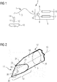
- FIG. 1 shows an optical scalpel 1 of a surgical sheath device 2.
- the optical scalpel comprises a light guide 3, which is connected at its proximal end 4 to supply unit 5.
- the light guide 3 is usually a glass fiber or a partially or entirely made of plastic fiber.
- a processing light source 6 and a marker light source 7 are located in the supply unit 5.
- a laser radiation 8 emitted by the processing light source 6 and a marker light 9 emitted by the marker light source 7 are fed together via a suitable coupling device 10 to the light guide 3.
- the laser radiation 8 and the marker light 9 is guided by the light guide 3 to a distal end 11, which is designed as a scalpel end 12.
- the laser radiation 8 emerging at the scalpel end 12 acts on the tissue 13 to be treated.
- the marking light 9 serves to mark the area to be treated before supplying the laser radiation 8.
- the marking light 9 can therefore be supplied alternately with the laser radiation 8 or permanently, even during the application of the laser radiation 8, are supplied.
- a holding device 14 may be provided for guiding the optical scalpel 1.
- the optical scalpel 1 laser radiation 8 and 9 marker light are guided over the same optical fiber 3.
- the marker light 9 it is also conceivable for the marker light 9 to provide its own light guide 3, with which the marker light 9 is supplied to the treatment location
- the processing light source 6 generally comprises a laser radiation 8 emitting laser. But instead of such a laser can also incoherent Light emitting light source can be used. In this respect, the use of the laser radiation 8 is not absolutely necessary. Nevertheless, in a further consequence, only laser radiation 8 is used. However, this is by no means restrictive.
- the mode of action of the laser radiation 8 it should be noted that, as is known, with higher intensity of the laser radiation 8, the interaction with the tissue 13 to be treated increases. On the one hand, the light energy radiated by laser radiation 8 is converted into heat, so that, starting from a certain temperature, there is a structural change in the proteins in the tissue 13 (denaturation). As a result, in particular, a desired hemostatic effect occurs.
- the laser radiation 8 of the processing laser 6 By the action of the laser radiation 8 of the processing laser 6, it further leads to the effect that the water contained in the tissue 13 evaporates. This evaporation can be partly explosive. The remaining tissue 13 has a correspondingly smaller volume. Therefore, the described effect for separating tissue layers can be used, whereby it can come at the same time to the already mentioned coagulation effect (cauterization) in the wound area.
- the introduced energy or intensity and the irradiated application field other known effects, such as further photoablative, -disruptive, -dynamic, -biological or similar interactions conceivable.
- the use in a range between 30 nm and 50,000 nm is possible in principle, preferably a range between 150 nm and 10,600 nm and particularly advantageously a range between 400 nm and 2000 nm comes. Especially in the latter area, a high degree of absorption of the water contained in the blood plasma has a positive effect.
- the conceivable power range is between 0.1 W and 100 GW in the so-called "peak power pulsed mode".
- powers between 0.1 W and 10 MW are used.
- the scalpel end 12 Due to the scalpel end 12 also a mechanical cutting of the fabric 13 can be effected.
- the scalpel end 12 is shaped in particular in such a way that a mechanical separation of the fabric 13 with and without the laser radiation 8 is made possible.
- the additional use of the laser radiation 8 results in addition to the mechanical action of the scalpel end 12 to an additional interaction with the tissue 13 such as the closure, injured vessels.
- the used laser radiation 8 does not merely serve to heat the scalpel end 12. Rather, the laser radiation 8 is emitted at the scalpel end 12 and it comes to the already mentioned above interaction with the tissue thirteenth
- the light guide 3 and the scalpel end 12 are integrally formed. Unitary means here are that the light guide 3 and the scalpel end 12 are formed from one and the same workpiece or component. For example, it is conceivable that the scalpel end 12 is formed by corresponding processing or reshaping of the optical waveguide 3 used in the region of the scalpel end 12. Of course, very different, correspondingly known machining and forming techniques come into consideration, which are generally known to the person skilled in the art.
- the one-piece design results in a conceivably simple construction. Cleaning, disinfection and the like, are greatly simplified due to the one-piece. By saving a variety of fasteners, of course, results in a corresponding cost advantage.
- a in FIG. 1 not shown connecting element may be provided, which allows to connect the light guide 3 to the housing 15.
- At least one processing light source 6 is usually formed by at least one laser, of course, very different laser sources and wavelengths with different powers, depending on their desired medical properties, can be used.
- Examples are frequently used laser sources such as NdYAG, ErbYAG laser, GaAs diode laser, or CO 2 laser, which, depending on the desired Application and thus selected wavelength and power range for coagulation, sublimation or heating of the tissue to be treated 13 can be selected.
- laser sources such as NdYAG, ErbYAG laser, GaAs diode laser, or CO 2 laser, which, depending on the desired Application and thus selected wavelength and power range for coagulation, sublimation or heating of the tissue to be treated 13 can be selected.
- At least one further marking light source 7 is provided for marking a treatment area.
- this marker light source 7 may also be a laser, with the selected wavelength range and power range enabling optical marking on the tissue 13 to be treated. An interaction with the fabric 13, as described for the laser of the processing light source 6 is not provided.
- the marking light source 7 thus facilitates positioning of the scalpel end 12 relative to a surface of the tissue 13 to be treated.
- the marking light source 7 is selected in terms of its properties, in particular with regard to the beam divergence of the marking light 9 emitted by it, such that a formed marking has the same geometry as a laser beam 8 formed by FIG. 5 illustrated focal spot 29 on the surface of the fabric thirteenth
- the marking light 9 of the marking light source 7 can be emitted further to the surface of the tissue 13 during the delivery of the laser radiation 8, or the delivery of the marking light 9 can also be interrupted, in particular if the laser radiation 8 comprises light in the visible wavelength range. If, in contrast, the laser radiation 8 lies in a non-visible wavelength range, the marking light 9 can also be used for example to mark the emission of the laser radiation 8 and then emerge from the scalpel end 12, even if laser radiation 8 emerges from the scalpel end 12.
- FIG. 2 shows a perspective view of the scalpel end 12 of the optical scalpel 1.
- the scalpel end 12 is thereby by a wedge-shaped taper formed of the light guide 3.
- the optical waveguide 3 extends along a longitudinal axis 15.
- An outer side 16 of the optical waveguide 3 has a cylindrical basic shape 17 along a longitudinal axis 15.
- the basic shape 17 has, in particular, an at least approximately circular cross-section 18 FIG. 2 shown only by way of example, two-sided processing of the light guide 3 can already be formed a correspondingly advantageous to use scalpel 2.
- two wedge surfaces 19 are formed, which intersect in a pointed front edge 20.
- the wedge surfaces 19 are bounded in each case by a side edge 21 which runs at least approximately parabolically and delimits the respective wedge surface 19 from the outside 16.
- the front edge 20 extends over the entire cross section 18 of the light guide 3. At the two outer ends of the front edge 20 forms the front edge 20 with the side edges 21 corners 22. The corners 22 are thus on the outside 16 of the light guide 3. At least one of Corners 22 is formed at the distal end 11 of the light guide 3 Thomasfase 23, for example, where the side edges 21 are marked with the dashed lines circles. There, the side edges 21 exert the function of a cutting edge.
- FIGS. 3 and 4 another embodiment is shown.
- the distal end 11 of the optical fiber 3 has been processed only from one side.
- the original optical waveguide 3 the cylindrical basic shape 17, so its distal end 11 is bounded by the outer side 16 and a circular end face 24.
- a bevel 25 is formed at its distal end 11.
- the chamfering surface 25 is limited to the outer side 16 by side edges 26 and the end face 24 through the front edge 27.
- the end face 24 no longer has a circular outline, but has the shape of a circle segment which is limited to the outside 16 through an outer edge 28.
- a corner 22 is formed at that point in which the end face 24 of the light guide 3, the outer side 16 of the light guide 3 and the aforementioned bevel 25 meet.
- a scalpel end 12 according to the invention is formed at the distal end 11 of the light guide 3.
- FIG. 5 illustrates the operation of the optical scalpel 1 using an embodiment with two Abschrägungs vom 25, whose projected to the cross section 18 normals occupy an angle less than 180 °.
- Scalpel ending 12 has been formed, for example, by a double machining of the distal end 11 of an originally cylindrical optical waveguide 3.
- two chamfer surfaces 25 each having an associated front edge 20, an approximately circular segment-shaped outline of the end face 24 and three corners 22 as shown in particular arise FIG. 6 is recognizable.
- the laser radiation 8 acts as a primary tool, the laser radiation 8.
- the longitudinal axis 15 of the scalpel end 12 is aligned normal to the surface of the fabric 13, so that the end face 24 is parallel to the surface of the fabric 13.
- the end face 24 is further guided over the surface of the fabric 13 at a distance d.
- the dimensions of a focal spot 29 formed by the laser radiation 8 depend, on the one hand, on the dimensions of the end face 24 and on the other hand on the distance d of the end face 24 to the surface of the fabric 13. The reason for this is the known divergence of the laser radiation 8, which increases the focal spot 29 with increasing distance d.
- the beam exit occurs, as shown, over the entire end face 24.
- FIG. 5 results in a so-called coagulation zone 30, which includes both the cutting base 31 and the cutting edges 32.
- coagulation zone 30 includes both the cutting base 31 and the cutting edges 32.
- Karbonisationszone 33 which by selecting adjustment parameters of Processing light source 6 also can not occur.
- the tissue 13 located there can be removed by the laser radiation 8.
- a wedge-shaped Thomasfase 23 formed at the distal end 11 of the optical waveguide 3 is formed.
- wedge-shaped means any kind of a tapered to Thomasfase 23 shape.
- the size of the focal spot 29 also changes. In this way, a selection with regard to the focusing on the area to be treated can also be made.
- the optical scalpel 1 according to the invention thus also makes it possible to use the mechanical cutting action of the scalpel end 12. This thus permits a particularly advantageous use of the optical scalpel 1 according to the invention, in particular for surgical applications in which, on the one hand, a mechanical separation of tissue 13 is preferred and, on the other hand, immediate coagulation (coagulation) is desired.
- FIG. 7 Figure 1 illustrates a situation in which the aforementioned mechanical cutting action is utilized to adequately separate the fabric 13.
- a preferred cutting direction is marked with S.
- the scalpel end 12 is thus designed so that a mechanical cutting property, similar to that of a classical scalpel is achieved.
- the laser radiation 8 predominantly exits via the end face 24 and coagulates directly behind the cut through the chamfer 23 the bleeding of the wound.
- the laser radiation 8 and the heating of the scalpel end 12 by means of the laser radiation 8 is not only used for cauterization or coagulation (coagulation) of the blood emerging during cutting, so that only the cut edges in the tissue 13 are coagulated. Rather, the incision wound is completely coagulated even if it comes to a gaping incision gap and the cutting base 31 widened. The resulting surface is sufficiently coagulated when using the device described herein.
- the marking light 9 as well as the laser radiation 8 can predominantly exit via the end face 24 and thereby reliably mark the treatment location.
- the scalpel end 12, as has already been described in connection with Figure 5, as well as from a distance d from a tissue 13 can be used without contact as an irradiation applicator (for example for point and area coagulation or for heating a defined body area).
- an irradiation applicator for example for point and area coagulation or for heating a defined body area.
- the thus executed light guide 3 with the scalpel end 12 can also be produced inexpensively and has a simple structure by which energy losses are avoided by coupling with other materials.
- a light guide 3 has the circular cross-section 18.
- a polygonal cross-section 34 At an arbitrary distance from the distal end 11 of the light guide 3 and its end face 24, the polygonal cross section 34 of the scalpel end 12 merges into the, for example circular, cross section 18 of the light guide 3.
- the at least one light guide 3 has a constant polygonal cross-section 34 over its entire length.
- At least one corner 22 of the polygonal cross-section 34 forms a wedge-shaped cutting chamfer 23, which lies at least approximately in the direction of the longitudinal extension of the optical waveguide 3.
- the term "wedge-shaped” is understood to mean any type of tapered shape towards the chamfer 23.
- a form already preselected for the light guide 3 can be used for the scalpel end 12.
- An aforementioned additional processing of that area through which the scalpel end 12 is formed is not necessary.
- Such an embodiment further allows a shortening of the light guide 3, in particular at its second end, without the geometry described above being changed. This can be done, for example, during a surgical procedure, with a short interruption of the procedure.
- the shortened second end of the light guide 3 can also be used as a scalpel end 12, with the advantages mentioned above.
- the end face 24 of the scalpel end 12 is configured such that at least two wedge-shaped Thomasfasen 23 are formed with at least approximately the same or different wedge angle 35.
- the respective wedge angle 35 can be used on the scalpel end 12, for example for different methods.
- a polygonal cross-section 34 could also be designed such that a double chamfer 23 forms, in which two identical or different wedge angles 35 interact with the fabric 13.
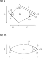
- FIG. 9 shows an embodiment whose end face 24 has a deltoid-shaped cross-section.
- FIG. 9 shows an embodiment whose end face 24 has a deltoid-shaped cross-section.
- wedge angle 35 of a wedge-shaped chamfer 23 is advantageously a range between 5 ° and 120 °, in particular between 25 ° and 50 ° into consideration. As can be appreciated, the appropriate selection of the wedge angle 35 assists in the aforementioned mechanical cutting action.
- the end faces 24 are each aligned at right angles to the longitudinal axis 15.
- the end faces 24 may be aligned so that the laser radiation 8 and the marker light 9 are broken when passing through the end face 24 to the chamfer 23 in order to achieve that the coagulation zone 30 comes closer to the scalpel end 12 to rest.
- angles of inclination of the end face 24 to the longitudinal axis 15 in the range of 45 ° to 90 ° are conceivable.
- the end face 24 but occupy an angle between 80 ° and 90 ° to the longitudinal axis 15.
- a surgical instrument based on a light guide 3 is formed.
- this can also be optionally used as a cautery.
- the simple construction allows a cost-effective production.
- the structure of the invention reduces Einkoppellage and cleaning and sterilization effort.
Landscapes
- Health & Medical Sciences (AREA)
- Surgery (AREA)
- Physics & Mathematics (AREA)
- Life Sciences & Earth Sciences (AREA)
- Engineering & Computer Science (AREA)
- Medical Informatics (AREA)
- Nuclear Medicine, Radiotherapy & Molecular Imaging (AREA)
- Electromagnetism (AREA)
- Optics & Photonics (AREA)
- Biomedical Technology (AREA)
- Heart & Thoracic Surgery (AREA)
- Otolaryngology (AREA)
- Molecular Biology (AREA)
- Animal Behavior & Ethology (AREA)
- General Health & Medical Sciences (AREA)
- Public Health (AREA)
- Veterinary Medicine (AREA)
- Laser Surgery Devices (AREA)
Abstract
Description
- Die vorliegende Erfindung betrifft ein optisches Skalpell bestehend aus zumindest einem Lichtleiter, mit einem proximalen und einem, vom proximalen Ende abgewendeten, distalen Ende, wobei an dessen proximalen Ende zumindest eine Bearbeitungslichtquelle anschließbar ist.
- Die Erfindung betrifft ferner eine chirurgische Schneidevorrichtung.
- Die Verwendung von hochenergetischer Strahlung, insbesondere von Laserstrahlung, im medizinischen Bereich, ist sowohl für die Behandlung von außen (ab externo), als auch bei endoskopischen Behandlungen (ab interno) entsprechend bekannt. Als Vorteil ist dabei anzuführen, dass die Verwendung von energiereichem Licht, insbesondere Laserstrahlung, die Applikation von photothermischen, bzw. photoinduzierten Eigenschaften erlaubt. Der teilweise gewünschte Gewebetrennungseffekt lässt sich so alleinstehend ebenso erzielen, wie eine Kombination mit photoinduzierten chemischen, physikalischen oder biologischen Prozessen. Im Vergleich zur Verwendung einer klassischen mechanisch agierenden Klinge zur Gewebetrennung, lassen sich weitere Eigenschaften einzeln oder kombiniert hinzufügen. Ein weiterer großer Vorteil bei der Verwendung von Laserstrahlung im chirurgischen Sinne ist, dass Blutgefäße beim Schnitt direkt verschlossen werden können und es somit zu nahezu keinen Blutungen kommt. Außerdem kann der Wundrand gleichzeitig erhitzt und so desinfiziert werden.
- Um die Laserstrahlung, welche beispielsweise von einem Festkörperlaser emittiert wird, entsprechend nutzen zu können, werden sogenannte Laser-Skalpelle genutzt.
- Beispielsweise zeigt die
EP 0 372 362 B1 ein Laserskalpell zur chirurgischen Anwendung, welches aufgrund der Werkstoffwahl eine möglichst hohe Arbeitstemperatur ermöglicht und eine gewisse Unempfindlichkeit auf Thermoschocks aufweist. Das bekannte Laserskalpell zeigt einen Aufbau, bei welchem die Skalpellspitze herausnehmbar, also vom Lichtleiter abtrennbar, ausgeführt ist. Dies ermöglicht eine entsprechend einfache und gründliche Reinigung. Um einen möglichst effektiven Übergang der Laserstrahlung vom Lichtleiter zur Skalpellspitze zu gewährleisten, ist die Skalpellspitze mit einer Bohrung versehen, in welche der Lichtleiter einführbar ist. Nachteilig ist der relativ komplizierte Aufbau. Weiters kommt es zwangsweise, durch die Einkopplung in die Skalpellspitze, zu entsprechenden Leistungsverlusten. Ein derartiger Aufbau kann des Weiteren zu einem erhöhten Aufwand bei der Reinigung führen. - Die
DE 10 2009 011 587 A1 zeigt einen Skalpellkörper, welcher aufgrund seiner Geometrie einen hohen Anteil der eingekoppelten Laserstrahlung an der Spitze des Skalpellkörper zur Verfügung stellen kann. Dabei liegt das Hauptaugenmerk auf einem definierten Einkoppelwinkel, über welchen die Laserstrahlung in den Skalpellkörper eingekoppelt wird. Der Lichtleiter, über welchen die Laserstrahlung geleitet wird, und der Skalpellkörper sind dabei getrennt ausgeführt. Dies hat den Nachteil, dass eine entsprechend genaue Positionierung der beiden zueinander notwendig ist, um die geometrischen Vorteile entsprechend nutzen zu können. Auch hier kommt es durch die Einkopplung zu den bereits erwähnten Leistungsverlusten. - Aus der
EP 3 067 005 A1 ist ferner eine Vorrichtung für die Laserchirurgie bekannt, bei der ein Lichtwellenleiter eine Laserquelle mit verschiedenen Handstücken verbindet, die jeweils mit einer optische Faser versehen sind. Die in den Handstücken vorgesehenen optischen Faser weisen distale Enden auf, die herkömmlichen mechanischen Skalpells nachgebildet sind. - Ausgehend von diesem Stand der Technik liegt der Erfindung die Aufgabe zugrunde, ein chirurgisches Instrument auf Basis eines Lichtleiters auszubilden, welches ähnlich einem Skalpell wirkt, das wahlweise auch als Kauter genutzt werden kann, möglichst einfach im Aufbau und kostengünstig herzustellen ist.
- Die Aufgabe wird gemäß der vorliegenden Erfindung dadurch gelöst, das distale Ende des Lichtleiters als Skalpellendung ausgebildet ist, die zumindest eine vom distalen Ende des Lichtleiters ausgehende, seitliche Schneidekante aufweist. Dadurch, dass das distale Ende des Lichtleiters als Skalpellendung ausgebildet ist, sind das eigentliche Skalpell und der Lichtleiter einstückig ausgebildet sind. Durch die Einstückigkeit ergibt sich ein denkbar einfacher Aufbau.
- Das als Skalpellendung ausgebildet distale Ende des Lichtleiters kann zumindest eine am distalen Ende des Lichtleiters angeordnete Ecke aufweisen, in der sich zumindest drei Kanten schneiden, von denen zumindest eine als Schneidekante ausgebildet ist, die sich von der Ecke aus wenigstens abschnittsweise in Richtung des proximalen Endes des Lichtleiters erstreckt. Dadurch ist sichergestellt, dass die Schneidekante über die gesamte Skalpellendung hinweg ausreichend abgestützt ist.
- Bei einer Ausführungsform ist vorgesehen dass im Querschnitt des Lichtleiters die Ecke der Skalpellendung weiter von der Mitte des Lichtleiters entfernt ist als von der Außenseite des Lichtleiters. Dadurch wird sichergestellt, dass die Schneidekante in die der Schneiderichtung entgegengesetzte Richtung mit so viel Material unterlegt ist, dass eine ausreichende Festigkeit der Schneidkante gewährleistet ist.
- Bei einer weiteren Ausführungsform ist vorgesehen, dass sich die Ecke der Skalpellendung im Querschnitt auf der Außenseite des Lichtleiters befindet. Die Ecke der Skalpellendung kann sich insbesondere auf der Umfangsfläche der zylinderförmigen Grundform des Lichtleiters befinden. Dadurch weist die Schneidekante die maximal mögliche Festigkeit auf.
- Bei einer weiteren Ausführungsform ist vorgesehen, dass sich eine vom distalen Ende des Lichtleiters ausgehende Schnittfase im Querschnitt des Lichtleiters zu der Schneidekante hin verjüngt. Dadurch ergibt sich eine langgestreckte, seitliche Schnittkante, mit der auch Schnitte mit großer Schnitttiefe möglich sind.
- Ferner kann vorgesehen sein, dass die Skalpellendung durch eine keilförmige Verjüngung des Lichtleiters ausgebildet ist. Durch zumindest eine dabei gebildete Ecke ist eine am distalen Ende des Lichtleiters liegende Schnittfase gebildet. Dadurch kann bereits durch ein zweiseitiges Bearbeiten des Lichtleiters eine entsprechend vorteilhaft zu nutzende Skalpellendung gebildet werden. Insofern ist diese Ausführungsform besonders einfach herstellbar.
- Bei einer Ausführungsform kann am distalen Ende des Lichtleiters eine quer zur Längsachse des Lichtleiters ausgerichtete Stirnfläche ausgebildet sein. Dadurch tritt das Licht aus der Lichtfaser überwiegend über die Stirnfläche aus und kann dort die nötige Koagulation der Schnittflächen bewirken. Die Stirnfläche kann insbesondere ungefähr im rechten Winkel zur Längsachse ausgerichtet sein und/oder eine Fläche zwischen der Hälfte und einem Drittel, Viertel, Fünftel, Sechstel oder Achtel der Querschnittsfläche des Lichtleiters einnehmen.
- Weiter kann vorgesehen sein, dass die am distalen Ende des Lichtleiters normal zu dessen Längserstreckung liegende Stirnfläche der Skalpellendung als Polygon ausgeführt ist. Durch zumindest eine Ecke der Stirnfläche, ist eine am distalen Ende des Lichtleiters liegende, keilförmige Schnittfase gebildet. Bei dieser Ausführungsform ist zum einen die Schnittfase besonders lang, so dass auch tiefe Schnitte vorgenommen werden können.
- Weiter kann vorgesehen sein, dass der zumindest eine Lichtleiter über seine gesamte Länge einen gleichbleibenden polygonen Querschnitt aufweist. Durch zumindest eine Ecke des polygonen Querschnittes ist eine keilförmige Schnittfase gebildet, welche zumindest annähernd in Richtung der Längserstreckung des Lichtleiters verläuft. Auf diese Weise kann eine bereits für die Lichtleiter vorgewählte Form vorteilhaft genutzt werden. Ein zusätzliches Bearbeiten jenes Bereichs, durch welchen die Skalpellendung und deren polygone Stirnfläche gebildet ist, ist nicht notwendig.
- Eine weitere Ausführungsform sieht vor, dass der polygone Querschnitt der Skalpellendung derart ausgestaltet ist, dass zumindest zwei Schnittfasen mit zumindest annähernd gleichem oder unterschiedlichem Keilwinkel gebildet sind. Bei zwei gleichartigen Keilwinkeln kann sich beispielsweise der Vorteil der bidirektionalen Nutzung ergeben.
- Unterschiedliche Keilwinkel können beispielsweise für unterschiedliche Verfahren angewandt werden. Dabei ist vorteilhaft vorgesehen, dass der Keilwinkel einer Schnittfase zwischen 5° und 120°, insbesondere zwischen 25° und 50° gewählt ist. Zum einen lässt dieser Winkelbereich eine vorteilhafte Fokussierung der Lichtenergie zu. Zum anderen wird bei entsprechender Winkelwahl die mechanische Schneidwirkung unterstützt.
- Das optische Skalpell kann Teil einer chirurgischen Schneidevorrichtung sein, in der das optische Skalpell in an die Bearbeitungslichtquelle angeschlossen ist.
- Bei einer Ausführungsform ist die eine Bearbeitungslichtquelle von einem Laser gebildet. Dadurch können Eigenschaften des Laserlichts, wie hohe Energiedichte und geringe Divergenz vorteilhaft genutzt werden.
- Weiters kann eine weitere Markierungslichtquelle, zur Markierung eines Behandlungsbereiches vorgesehen sein. Diese erlaubt ein erleichtertes Positionieren der Skalpellendung relativ zum zu behandelnden Gewebe.
- Das von der Markierlichtquelle ausgehende Markierlicht mit Hilfe einer Koppelvorrichtung zusammen mit der Laserstrahlung dem Lichtleiter zugeführt sein. Dadurch tritt das Markierlicht im Wesentlichen an der Stelle aus dem Lichtleiter aus, an der auch das Bearbeitungslicht den Lichtleiter verlässt. Insofern wird der Bereich auf den die Laserstrahlung einwirkt für den Benutzer zuverlässig markiert.
- Die gegenständliche Erfindung wird nachfolgend unter Bezugnahme auf die
Figuren 1 bis 10 erläutert, die beispielhaft, schematisch und nicht einschränkend verschiedene Ausgestaltungen der Erfindung zeigen. Dabei zeigt - Figur 1
- eine chirurgische Schneidevorrichtung,
- Figur 2
- ein Ausführungsbeispiel der Skalpellendung eines optischen Skalpells,
- Figur 3
- ein abgewandeltes Ausführungsbeispiel der Skalpellendung,
- Figur 4
- ein Längsschnitt durch das in die in
Figur 3 dargestellte Ausführungsbeispiel einer Skalpellendung, - Figur 5
- eine Darstellung, die die Wirkweise einer Skalpellendung veranschaulicht,
- Figur 6
- eine Vorderansicht auf die Skalpellendung aus
Figur 5 , - Figur 7
- eine Seitenansicht eines weiteren Ausführungsbeispiels des optischen Skalpells,
- Figuren 8 bis 10
- Vorderansichten von verschiedenen beispielhaften Skalpellendungen aus Richtung A in
Fig. 7 -
Figur 1 zeigt ein optisches Skalpell 1 einer chirurgischen Scheidevorrichtung 2. Das optische Skalpell umfasst einen Lichtleiter 3, der mit seinem proximalen Ende 4 an Versorgungseinheit 5 angeschlossen ist. Der Lichtleiter 3 ist üblicherweise eine Glasfaser oder eine teilweise oder ganz aus Kunststoff hergestellte Faser. In der Versorgungseinheit 5 befindet sich eine Bearbeitungslichtquelle 6 und eine Markierungslichtquelle 7. Eine von der Bearbeitungslichtquelle 6 abgegebene Laserstrahlung 8 und ein von der Markierlichtquelle 7 abgegebenes Markierlicht 9 werden über eine geeignete Koppelvorrichtung 10 zusammen dem Lichtleiter 3 zugeführt werden. Die Laserstrahlung 8 und das Markierlicht 9 wird vom Lichtleiter 3 zu einem distalen Ende 11 geführt, das als Skalpellendung 12 ausgebildet ist. Die an der Skalpellendung 12 austretende Laserstrahlung 8 wirkt auf zu behandelndes Gewebe 13 ein. Das Markierlicht 9 dient dazu den zu behandelnden Bereich vor dem Zuführen der Laserstrahlung 8 zu markieren. Das Markierlicht 9 kann daher alternierend mit der Laserstrahlung 8 zugeführt werden oder dauerhaft, auch während der Anwendung der Laserstrahlung 8, zugeführt werden. Zum Führen des optischen Skalpell 1 kann eine Haltevorrichtung 14 vorgesehen sein. - Bei dem in
Figur 1 dargestellten Ausführungsbeispiel des optischen Skalpells 1 werden Laserstrahlung 8 und Markierlicht 9 über denselben Lichtleiter 3 geführt. Es ist jedoch auch denkbar für das Markierlicht 9 einen eigenen Lichtleiter 3 vorzusehen, mit dem das Markierlicht 9 dem Behandlungsort zugeführt wird - Die Bearbeitungslichtquelle 6 umfasst in der Regel einen Laserstrahlung 8 emittierenden Laser. Anstelle eines derartigen Lasers kann aber auch eine inkohärentes Licht abgebende Lichtquelle verwendet werden. Insofern ist die Nutzung der Laserstrahlung 8 nicht zwingend notwendig. Dennoch wird in weiterer Folge in diesem Zusammenhang, lediglich von Laserstrahlung 8 gesprochen. Dies ist jedoch keinesfalls einschränkend zu sehen. Zur Wirkweise der Laserstrahlung 8 sei angemerkt, dass bekanntermaßen bei höherer Intensität der Laserstrahlung 8 die Wechselwirkung mit dem zu behandelnden Gewebe 13 zunimmt. Die durch Laserstrahlung 8 eingestrahlte Lichtenergie wird zum einen in Wärme umgewandelt, sodass es, ab einer gewissen Temperatur, zu einer strukturellen Veränderung der Proteine im Gewebe 13 kommt (Denaturierung). Dadurch tritt insbesondere ein erwünschter, blutstillender Effekt ein.
- Durch das Einwirken der Laserstrahlung 8 des Bearbeitungslasers 6, kommt es weiter zum Effekt, dass das im Gewebe 13 enthaltene Wasser verdampft. Diese Verdampfung kann zum Teil explosionsartig verlaufen. Das zurückbleibende Gewebe 13 besitzt ein entsprechend kleineres Volumen. Daher kann der beschriebene Effekt zum Trennen von Gewebeschichten benutzt werden, wobei es gleichzeitig zum bereits erwähnten Gerinnungseffekt (Kauterisation) im Wundbereich kommen kann. Natürlich sind, abhängig von der Wellenlänge der Laserstrahlung 8, der eingebrachten Energie oder Intensität und dem bestrahlten Applikationsfeld auch andere bekannte Effekte, wie beispielsweise weitere photoablative, -disruptive, -dynamische,-biologische oder ähnliche Wechselwirkungen denkbar.
- Bezüglich der soeben erwähnten Wellenlänge der Laserstrahlung 8 sei angemerkt, das prinzipiell die Nutzung in einem Bereich zwischen 30 nm und 50.000 nm möglich ist, wobei vorzugsweise ein Bereich zwischen 150 nm und 10.600 nm und besonders vorteilhaft ein Bereich zwischen 400 nm und 2000 nm zur Anwendung kommt. Insbesondere im zuletzt genannten Bereich kommt ein hoher Absorptionsgrad des im Blutplasma enthaltenen Wassers positiv zum Tragen. Der denkbare Leistungsbereich liegt zwischen 0,1 W bis 100 GW im sogenannten "peak power pulsed mode". Vorzugsweise kommen Leistungen zwischen 0,1W und 10 MW zur Anwendung.
- Aufgrund der Skalpellendung 12 kann auch ein mechanisches Schneiden des Gewebes 13 bewirkt werden. Die Skalpellendung 12 ist insbesondere derart geformt, das ein mechanisches Trennen des Gewebes 13 mit und auch ohne die Laserstrahlung 8 ermöglicht wird.
- Die zusätzliche Nutzung der Laserstrahlung 8 führt neben dem mechanischen Einwirken der Skalpellendung 12 zu einer zusätzlichen Interaktion mit dem Gewebe 13 wie beispielsweise der Verschluss, verletzter Gefäße. Dabei dient die genutzte Laserstrahlung 8 jedoch nicht lediglich dazu die Skalpellendung 12 zu erwärmen. Vielmehr wird die Laserstrahlung 8 wird an der Skalpellendung 12 emittiert und es kommt zur bereits eingangs erwähnten Wechselwirkung mit dem Gewebe 13.
- Besonders hervorzuheben ist, dass der Lichtleiter 3 und die Skalpellendung 12 einstückig ausgebildet sind. Unter Einstückigkeit ist hier zu verstehen, dass der Lichtleiter 3 und die Skalpellendung 12 aus ein und demselben Werkstück oder Bauteil gebildet sind. Beispielsweise ist denkbar, dass die Skalpellendung 12 durch entsprechendes Bearbeiten oder Umformen des verwendeten Lichtleiters 3 im Bereich der Skalpellendung 12 gebildet wird. Dabei kommen selbstverständlich unterschiedlichste, entsprechend bekannte Bearbeitungs- und Umformtechniken in Betracht, die dem Fachmann grundsätzlich bekannt sind.
- Durch die Einstückigkeit ergibt sich ein denkbar einfacher Aufbau. Reinigung, Desinfektion und dergleichen, sind aufgrund der Einstückigkeit wesentlich vereinfacht. Durch die Einsparung diverser Verbindungselemente ergibt sich natürlich auch ein entsprechender Kostenvorteil. Selbstverständlich kann in bekannter Weise am besagten proximalen Ende 4 des Lichtleiters 3 ein in
Figur 1 nicht dargestelltes Verbindungselement vorgesehen sein, welches ermöglicht, den Lichtleiter 3 mit dem Gehäuse 15 zu verbinden. - Die erwähnte, zumindest eine Bearbeitungslichtquelle 6 wird in der Regel durch wenigstens einen Laser gebildet, wobei natürlich unterschiedlichste Laserquellen und Wellenlängen mit unterschiedlichen Leistungen, je nach ihren gewünschten medizinischen Eigenschaften, genutzt werden können.
- Lediglich beispielhaft seien häufig genutzte Laserquellen wie NdYAG, ErbYAG Laser, GaAs Diodenlaser, oder auch CO2 Laser genannt, welche je nach erwünschter Anwendung und damit gewählten Wellenlängen- und Leistungsbereich zur Koagulation, Sublimation oder Erwärmung des zu behandelnden Gewebes 13 gewählt werden können.
- Neben der eben erwähnten Bearbeitungslichtquelle 6 ist vorgesehen, dass zumindest eine weitere Markierungslichtquelle 7 zur Markierung eines Behandlungsbereiches vorgesehen ist. Natürlich kann es sich bei dieser Markierungslichtquelle 7 ebenfalls um einen Laser handeln, wobei der gewählte Wellenlängenbereich und Leistungsbereich ein optisches Markieren auf dem zu behandelnden Gewebe 13 ermöglicht. Eine Wechselwirkung mit dem Gewebe 13, wie es für den Laser der Bearbeitungslichtquelle 6 beschrieben wurde ist dabei nicht vorgesehen. Mithilfe der Markierungslichtquelle 7 wird somit ein Positionieren der Skalpellendung 12, relativ zu einer Oberfläche des zu behandelnden Gewebes 13 erleichtert. Vorzugsweise ist die Markierungslichtquelle 7 in ihren Eigenschaften, insbesondere bezüglich der Strahldivergenz des von ihr abgegebenen Markierlichtes 9, derart gewählt, das eine gebildete Markierung die gleiche Geometrie aufweist wie ein durch die Laserstrahlung 8 gebildeter, in
Figur 5 dargestellter Brennfleck 29 auf der Oberfläche des Gewebes 13. - Auf diese Weise ist ein Wirkbereich der Laserstrahlung 8 anhand der beschriebenen Markierung abschätzbar.
- Das Markierlicht 9 der Markierungslichtquelle 7 kann während der Abgabe der Laserstrahlung 8 weiter an die Oberfläche des Gewebes 13 abgegeben werden, oder die Abgabe des Markierlicht 9 kann währenddessen auch unterbrochen werden, insbesondere wenn die Laserstrahlung 8 Licht im sichtbaren Wellenlängenbereich umfasst. Falls dagegen die Laserstrahlung 8 in einem nicht sichtbaren Wellenlängenbereich liegt, kann das Markierlicht 9 beispielsweise auch zur Kennzeichnung der Emission der Laserstrahlung 8 verwendet werden und immer dann aus der Skalpellendung 12 austreten, wenn auch Laserstrahlung 8 aus der Skalpellendung 12 austritt.
-
Figur 2 zeigt eine perspektivische Ansicht der Skalpellendung 12 des optischen Skalpells 1. Die Skalpellendung 12 wird dabei durch eine keilförmige Verjüngung des Lichtleiters 3 ausgebildet. Hinsichtlich des Lichtleiters 3 ist inFigur 2 der derzeit übliche industrielle Standard dargestellt. Der Lichtleiter 3 erstreckt sich entlang einer Längsachse 15. Eine Außenseite 16 des Lichtleiters 3 weist dabei entlang einer Längsachse 15 eine sich zylindrische Grundform 17 auf. Die Grundform 17 verfügt insbesondere einen zumindest annähernd kreisförmigen Querschnitt 18. Durch ein, wie inFigur 2 lediglich beispielhaft dargestellt, zweiseitiges Bearbeiten des Lichtleiters 3 kann bereits eine entsprechend vorteilhaft zu nutzende Skalpellendung 2 gebildet werden. Durch die Bearbeitung des Lichtleiters 3 werden zwei Keilflächen 19 gebildet, die sich in einer spitzen Vorderkante 20 schneiden. In seitliche Richtung sind die Keilflächen 19 jeweils durch eine Seitenkante 21 begrenzt, die jeweils zumindest näherungsweise parabelförmig verläuft und die jeweilige Keilfläche 19 von der Außenseite 16 abgrenzt. Die Vorderkante 20 erstreckt sich über den gesamten Querschnitt 18 des Lichtleiters 3. An den beiden äußeren Enden der Vorderkante 20 bildet die Vorderkante 20 mit den Seitenkanten 21 Ecken 22. Die Ecken 22 liegen somit auf der Außenseite 16 des Lichtleiters 3. An zumindest einer der Ecken 22 ist eine am distalen Ende 11 des Lichtleiters 3 liegende Schnittfase 23 gebildet, beispielsweise dort wo die Seitenkanten 21 mit den gestrichelt eingezeichneten Kreisen gekennzeichnet sind. Dort üben die Seitenkanten 21 die Funktion einer Schneidekante aus. - In den
Figuren 3 und 4 ist ein weiteres Ausführungsbeispiel dargestellt. Bei diesem Ausführungsbeispiel ist das distale Ende 11 des Lichtleiters 3 nur von einer Seite bearbeitet worden. Weist, wie beispielhaft in denFiguren 3 und 4 dargestellt, der ursprüngliche Lichtleiter 3 die zylindrische Grundform 17 auf, so wird dessen distales Ende 11 von der Außenseite 16 und einer kreisförmigen Stirnfläche 24 begrenzt. Durch die zuvor erwähnte einseitige Bearbeitung des Lichtleiters 3 wird an dessen distalem Ende 11 eine Abschrägungsfläche 25 gebildet. Die Abschrägungsfläche 25 ist zur Außenseite 16 hin durch Seitenkanten 26 und zur Stirnfläche 24 hin durch die Vorderkante 27 begrenzt. Infolgedessen weist, wie insbesondere inFigur 3 erkennbar, die Stirnfläche 24 keinen kreisförmigen Umriss mehr auf, sondern hat die Gestalt eines Kreissegments, das zur Außenseite 16 hin durch eine Außenkante 28 begrenzt ist. Im Schnittpunkt von Seitenkante 26, Vorderkante 27 und Außenkante 28 sind die Ecken 22 gebildet. Dabei wird am distalen Ende 11 des Lichtleiters 3 jeweils eine Ecke 22 an jenem Punkt gebildet, in welchem die Stirnfläche 24 des Lichtleiters 3, die Außenseite 16 des Lichtleiters 3 und die erwähnte Abschrägungsfläche 25 aufeinandertreffen. Auf diese Weise wird am distalen Ende 11 des Lichtleiters 3 eine erfindungsgemäße Skalpellendung 12 ausgebildet. Selbstverständlich sind dabei auch mehrere Bearbeitungsflächen 21, wie beispielhaft inFigur 2 gezeigt, möglich. -
Figur 5 veranschaulicht die Wirkungsweise des optischen Skalpells 1 anhand eines Ausführungsbeispiels mit zwei Abschrägungsflächen 25, deren auf den Querschnitt 18 projizierten Normalen einen Winkel kleiner 180° einnehmen. Die inFigur 5 dargestellte Skalpellendung 12 wurde beispielsweise durch eine zweifache Bearbeitung des distalen Endes 11 eines ursprünglich zylindrischen Lichtleiters 3 gebildet. Infolge ergeben sich zwei Abschrägungsflächen 25 mit jeweils einer zugeordneten Vorderkante 20, ein annähernd kreissegmentförmiger Umriss der Stirnfläche 24 und drei Ecken 22 wie insbesondere anhandFigur 6 erkennbar ist. - Im dargestellten Fall, wirkt als primäres Werkzeug die Laserstrahlung 8. Dabei ist die Längsachse 15 der Skalpellendung 12 normal zur Oberfläche des Gewebes 13 ausgerichtet, so dass die Stirnfläche 24 parallel zur Oberfläche des Gewebes 13 liegt. Eine derartige Positionierung der Skalpellendung 12 ist jedoch lediglich beispielhaft. Die Stirnfläche 24 wird ferner in einem Abstand d über die Oberfläche des Gewebes 13 geführt. Die Abmessungen eines durch die Laserstrahlung 8 gebildeten Brennfleckes 29 sind zum einen von den Abmessungen der Stirnfläche 24 und zum anderen vom Abstand d der Stirnfläche 24 zur Oberfläche des Gewebes 13 abhängig. Grund dafür ist die bekannte Divergenz der Laserstrahlung 8, welche mit steigenden Abstand d den Brennfleck 29 vergrößert. Der Strahlaustritt erfolgt, wie dargestellt über die gesamte Stirnfläche 24. Das mögliche mechanische Einwirken der Skalpellendung 12 auf das zu behandelndes Gewebe 13, kommt in diesem Fall nicht zur Anwendung. Wie in
Figur 5 schematisch dargestellt ist, ergibt sich eine sogenannte Koagulationszone 30, welche sowohl den Schnittgrund 31 als auch die Schnittflanken 32 umfasst. Oberhalb der Koagulationszone 30 befindet sich eine Karbonisationszone 33, die durch Wahl von Einstellparametern der Bearbeitungslichtquelle 6 auch nicht auftreten kann. Das dort befindliche Gewebe 13 kann durch die Laserstrahlung 8 entfernt werden. - Es sei angemerkt, dass bei dem in
Figur 5 und 6 dargestellten Ausführungsbeispiel alle drei Ecken 22 auf der Außenseite 16 des Lichtleiters 3 liegen. Zum mechanischen Scheiden in eine Schneiderichtung S wird vor allem die Ecke 22 verwendet, in der sich die beiden Abschrägungsflächen 25 schneiden, da die Materialstärke D der Skalpellendung 12 in die Schneiderichtung S am größten ist. Es sei angemerkt, dass sich in der Ecke vier Kanten schneiden, nämlich die beiden Seitenkanten 26 und die beiden Vorderkanten 27. Ferner sei angemerkt, dass der Durchmesser und damit die Materialstärke D typischerweise 1,2 mm beträgt. Schließlich sei angemerkt, dass die Skalpellendung 12 typischerweise etwa 5 mm lang ist. - Bei einem in
Figur 6 gestrichelt eingezeichneten, weiteren Abtrag der Abschrägungsflächen 25 kann sich eine in Längsrichtung des Lichtleiters 3 verlaufende Schnittfase 23 ergeben. In der Regel werden die Abschrägungsflächen 25 aber nur so stark abgetragen, dass sich die Ecke 22, von der die Schnittfase 23 ausgeht, in radiale Richtung näher an der Außenseite 16 des Lichtleiters 3 als an der Mitte M des Querschnitts 18 befindet. - Wie weiters, insbesondere in den
Figur 7 bis 10 verdeutlicht ist, ist vorteilhaft die, am distalen Ende 11 des Lichtleiters 3 normal zu dessen Längserstreckung liegende Stirnfläche 24 der Skalpellendung 12, als Polygon ausgeführt. Dabei wird durch zumindest eine Ecke 22 der Stirnfläche 24 eine am distalen Ende 11 des Lichtleiters 3 liegende, keilförmige Schnittfase 23 gebildet. In diesem Zusammenhang ist dabei unter keilförmig jede Art einer sich zur Schnittfase 23 hin verjüngenden Form zu verstehen. - Je nach gewählter Größe der Stirnfläche 24 und gewählter Polygonform ändert sich auch die Größe des Brennfleckes 29. Auf diese Weise kann auch eine Auswahl in Bezug auf die Fokussierung auf den zu behandelnden Bereich getroffen werden. Zum anderen ergibt sich durch eine keilförmige Schnittfase 23 eine vorteilhafte Geometrie, in Hinsicht auf die mechanische Schneidwirkung der Skalpellendung 12. Je nach zu behandelnden Gewebe 13 oder medizinischen Anwendungsgebiet, besteht mit dem erfindungsgemäßen optischen Skalpell 1 somit auch die Möglichkeit, die mechanische Schneidwirkung der Skalpellendung 12 zu nutzen. Dies erlaubt somit eine besonders vorteilhafte Nutzung des erfindungsgenmäßen optischen Skalpells 1 insbesondere für chirurgische Anwendungen, bei welchen zum einen eine mechanische Trennung von Gewebe 13 bevorzugt wird und zum anderen eine unmittelbare Blutgerinnung (Koagulation) erwünscht ist.
- In diesem Zusammenhang ist
Figur 7 eine Situation dargestellt, in welcher die zuvor erwähnte mechanische Schneidwirkung genutzt wird, um das Gewebe 13 entsprechend zu trennen. Eine bevorzugte Schneiderichtung ist dabei mit S gekennzeichnet. Die Skalpellendung 12 ist also so ausgeführt, dass auch eine mechanische Schnitteigenschaft, ähnlich dem eines klassischen Skalpells, erreicht wird. Weiterhin tritt die Laserstrahlung 8 überwiegend über die die Stirnfläche 24 aus und koaguliert unmittelbar hinter dem Schnitt durch die Schnittfase 23 die Blutung der Wunde. - Somit wird die Laserstrahlung 8 und die Erwärmung der Skalpellendung 12 mithilfe der Laserstrahlung 8 nicht nur zur Kauterisation oder Koagulation (Gerinnen) des beim Schneiden austretenden Blutes genutzt, so dass lediglich die Schnittkanten im Gewebe 13 koaguliert werden. Vielmehr wird die Schnittwunde auch dann vollständig koaguliert, wenn es zu einem aufklaffenden Schnittspalt kommt und sich der Schnittgrund 31 verbreitert. Die dadurch entstehende Oberfläche wird bei der Verwendung der hier beschriebenen Vorrichtung ausreichend koaguliert.
- Ferner sei angemerkt, dass das Markierlicht 9 ebenso wie die Laserstrahlung 8 überwiegend über die Stirnfläche 24 austreten kann und dadurch den Behandlungsort zuverlässig markiert.
- Weiter kann die Skalpellendung 12, so wie dies bereits im Zusammenhang mit Figur 5 beschrieben wurde, ebenso noch aus einem Abstand d von einem Gewebe 13 berührungsfrei als Bestrahlungsapplikator (zum Beispiel zur Punkt- und Flächenkoagulation oder zur Erwärmung eines definierten Körperareales) eingesetzt werden.
- Der so ausgeführte Lichtleiter 3 mit der Skalpellendung 12 kann ferner kostengünstig hergestellt werden und hat einen einfachen Aufbau, durch welchen Energieverluste durch Kopplung mit anderen Materialien vermieden werden.
- Wie bereits im Zusammenhang mit
Figur 2 erwähnt, ist der derzeitige industrielle Standard, dass ein Lichtleiter 3 den kreisförmigen Querschnitt 18 aufweist. Bei der inFigur 7 dargestellten Variante, weisen lediglich die Skalpellendung 12 oder das distale Ende 11 des Lichtleiters 3, einen polygonen Querschnitt 34 auf. In einem beliebigen Abstand vom distalen Ende 11 des Lichtleiters 3 und dessen Stirnfläche 24 geht der polygone Querschnitt 34 der Skalpellendung 12 in den, beispielsweise kreisförmigen, Querschnitt 18 des Lichtleiters 3 über. Es ist auch möglich, dass der zumindest eine Lichtleiter 3 über seine gesamte Länge einen gleichbleibenden polygonen Querschnitt 34 aufweist. Zumindest eine Ecke 22 des polygonen Querschnittes 34, bildet dabei eine, zumindest annähernd in Richtung der Längserstreckung des Lichtleiters 3 liegende, keilförmige Schnittfase 23. Wiederum sei angemerkt, dass unter keilförmig jede Art einer sich zur Schnittfase 23 hin verjüngenden Form zu verstehen ist. - Dadurch kann eine bereits für den Lichtleiter 3 vorgewählte Form für die Skalpellendung 12 genutzt werden. Ein zuvor erwähntes, zusätzliches Bearbeiten jenes Bereichs, durch welchen die Skalpellendung 12 ausgebildet ist, ist nicht notwendig. Eine derartige Ausführung erlaubt weiter ein Kürzen des Lichtleiters 3, insbesondere an dessen zweitem Ende, ohne dass die zuvor beschriebene Geometrie verändert wird. Dies kann beispielsweise auch während eines chirurgischen Eingriffes, bei kurzer Unterbrechung der Prozedur, erfolgen. Auch das gekürzte zweite Ende des Lichtleiters 3 kann als Skalpellendung 12, mit den zuvor erwähnten Vorteilen weiter genutzt werden.
- Wie ebenfalls in
Figur 7 erkennbar ist, kann vorgesehen sein, dass die Stirnfläche 24 der Skalpellendung 12 derart ausgestaltet ist, dass zumindest zwei keilförmige Schnittfasen 23 mit zumindest annähernd gleichem oder unterschiedlichem Keilwinkel 35 gebildet sind. InFigur 8 ist eine derartige rautenförmige Stirnfläche 24 dargestellt. Typische Abmessungen sind für die Breite B = 0,8 mm, für die Länge L = 0,6 mm und für die Kantenlänge K = 0,7 mm. Bei zwei gleichartigen Keilwinkel 35 ergibt sich der Vorteil der richtungsunabhängigen Nutzung. - Weist die Skalpellendung 12 dagegen unterschiedliche Keilwinkel 35 auf, kann an der Skalpellendung 12 der jeweilige Keilwinkel 35 beispielsweise für unterschiedliche Verfahren zur Anwendung kommen. In diesem Zusammenhang sei beispielsweise auf die Ausführungsvarianten, welche in den
Figuren 9 und 10 dargestellt sind, hingewiesen. Dabei handelt es sich lediglich um beispielhafte Ausführungsvarianten der Stirnfläche 24. Beispielsweise könnte ein polygoner Querschnitt 34 auch derart ausgeführt sein, dass sich eine doppelte Schnittfase 23 bildet, bei welchen zwei gleiche oder auch unterschiedliche Keilwinkel 35 mit dem Gewebe 13 wechselwirken.Figur 9 zeigt ein Ausführungsbeispiel, dessen Stirnfläche 24 einen deltoidförmigen Querschnitt aufweist. InFigur 9 sind typische Abmessungen für die Breite B = 0,8 mm, für die Längen L1= 0,4 mm und Länge L2 = 0,8 mm sowie für die Kantenlänge K = 0,9 mm.Figur 10 zeigt schließlich ein Ausführungsbeispiel, dessen Stirnfläche 24 einen mandelförmigen Querschnitt aufweist. Typische Abmessungen sind für die Breite B 0,4 mm und für die Länge L = 1,2 mm. - Für den zuvor erwähnten Keilwinkel 35 einer keilförmigen Schnittfase 23 kommt vorteilhaft ein Bereich zwischen 5° und 120°, insbesondere zwischen 25° und 50° in Betracht. In nachvollziehbarer Weise, wird durch die entsprechende Auswahl des Keilwinkels 35, die zuvor erwähnte mechanische Schneidwirkung unterstützt.
- Es sei angemerkt, dass bei den in den
Figuren 3 bis 10 dargestellten Ausführungsbeispielen mit Stirnflächen 24, die Stirnflächen 24 jeweils im rechten Winkel zur Längsachse 15 ausgerichtet sind. Bei weiteren abgewandelten Ausführungsbeispielen können die Stirnflächen 24 so ausgerichtet sein, dass die Laserstrahlung 8 und das Markierlicht 9 beim Durchgang durch die Stirnfläche 24 zur Schnittfase 23 hin gebrochen werden, um zu erreichen, dass die Koagulationszone 30 näher an der Skalpellendung 12 zum Liegen kommt. Denkbar sind insbesondere Neigungswinkel der Stirnfläche 24 zur Längsachse 15 im Bereich von 45° bis 90°. - Im Regelfall wird die Stirnfläche 24 aber einen Winkel zwischen 80° und 90° zur Längsachse 15 einnehmen.
- Durch die vorliegende Erfindung wird ein chirurgisches Instrument auf Basis eines Lichtleiters 3 ausgebildet. Neben der Nutzung als Skalpell, kann dieses auch wahlweise als Kauter genutzt werden. Der einfache Aufbau erlaubt eine kostengünstige Herstellung. Weiters reduziert der erfindungsgemäße Aufbau Einkoppelverluste und Reinigungs- und Sterilisationsaufwand.
Claims (15)
- Optisches Skalpell (1) mit zumindest einem Lichtleiter (3), der ein proximales Ende (4) und ein dem proximalen Ende (4) entgegengesetztes distales Ende (11) aufweist und der über das proximale Ende (4) an zumindest eine Bearbeitungslichtquelle (6) anschließbar ist,
dadurch gekennzeichnet, dass
das distale Ende (11) des Lichtleiters (3) als Skalpellendung (12) ausgebildet ist, die zumindest eine vom distalen Ende (11) des Lichtleiters (3) ausgehende, seitliche Schneidekante (21, 26) aufweist. - Optisches Skalpell (1) nach Anspruch 1,
dadurch gekennzeichnet, dass
die Skalpellendung (12) eine am distalen Ende (11) des Lichtleiters (3) angeordnete Ecke (22) aufweist, in der sich zumindest drei Kanten (20, 21, 26, 27, 28) scheiden, von denen zumindest eine als Schneidekante (21, 26) ausgebildet ist, die sich von der Ecke (22) aus wenigstens abschnittsweise in Richtung des proximalen Endes (4) des Lichtleiters (3) erstreckt. - Optisches Skalpell (1) nach Anspruch 2,
dadurch gekennzeichnet, dass
im Querschnitt (18, 34) des Lichtleiters (3) die Ecke (22) der Skalpellendung (12) weiter von der Mitte des Lichtleiters (3) entfernt ist als von der Außenseite (16) des Lichtleiters (3). - Optisches Skalpell (1) nach Anspruch 3,
dadurch gekennzeichnet, dass
sich die Ecke (22) der Skalpellendung (12) im Querschnitt (18, 34) auf der Außenseite (16) des Lichtleiters (3) befindet. - Optisches Skalpell (1) nach einem der Ansprüche 1 bis 4,
dadurch gekennzeichnet, dass
die Skalpellendung (12) eine vom distalen Ende (11) des Lichtleiters (3) ausgehende Schnittfase (23) aufweist, die sich im Querschnitt (18, 34) des Lichtleiters (3) zu der Schneidekante (21, 26) hin verjüngt. - Optisches Skalpell (1) nach einem der Ansprüche 1 bis 5,
dadurch gekennzeichnet, dass
die Skalpellendung (12) durch eine sich in Längsrichtung erstreckende keilförmige Verjüngung des Lichtleiters (3) ausgebildet ist und durch zumindest eine dabei gebildeten Ecke (22) die Spitze der Skalpellendung (12) bildet, von der aus eine am distalen Ende (11) des Lichtleiters (3) liegende Schnittfase (23) ausgeht. - Optisches Skalpell (1) nach einem der Ansprüche 1 bis 5,
dadurch gekennzeichnet, dass
am distalen Ende (11) des Lichtleiters (3) eine quer zur einer Längsachse (15) des Lichtleiters ausgerichtete Stirnfläche (24) ausgebildet ist. - Optisches Skalpell (1) nach Anspruch 7,
dadurch gekennzeichnet, dass
eine am distalen Ende (11) des Lichtleiters (3) normal zu dessen Längsachse ausgerichtete Stirnfläche (24) der Skalpellendung (12), als Polygon ausgeführt ist und zumindest eine Ecke (22) der Stirnfläche (24) die Ecke der Skalpellendung (12) bildet, von der aus die am distalen Ende (11) des Lichtleiters (3) liegende Schnittfase (23) ausgeht. - Optisches Skalpell (1) nach Anspruch 8,
dadurch gekennzeichnet, dass
der zumindest eine Lichtleiter (3) über seine gesamte Länge einen gleichbleibenden polygonen Querschnitt (34) aufweist und zumindest eine Ecke (22) des polygonen Querschnittes (34) die Ecke der Skalpellendung (12) bildet, von der aus die sich entlang der Längsachse (15) des Lichtleiters (3) erstreckende Schnittfase (23) ausgeht. - Optisches Skalpell (1) nach einem der Ansprüche 7 bis 9,
dadurch gekennzeichnet, dass
von der Stirnfläche (24) der Skalpellendung (12) zumindest zwei Schnittfasen (23) ausgehen. - Optisches Skalpell (1) nach einem der Ansprüche 5 bis 10,
dadurch gekennzeichnet, dass
die Schnittfase (23) keilförmig ausgebildet ist und der Keilwinkel (35) der keilförmigen Schnittfase (23) zwischen 5° und 120°, insbesondere zwischen 25° und 50° gewählt ist. - Schneidevorrichtung (2) für die Chirurgie mit zumindest einer Bearbeitungslichtquelle (6) und wenigstens einem daran angeschlossenen optischen Skalpell (1), dadurch gekennzeichnet, dass das optische Skalpell (1) nach einem der Ansprüche 1 bis 11 ausgebildet ist.
- Schneidevorrichtung (2) für die Chirurgie nach Anspruch 12,
dadurch gekennzeichnet, dass
die zumindest eine Bearbeitungslichtquelle (6) durch einen Bearbeitungslaser (6) gebildet ist. - Schneidevorrichtung (2) nach Anspruch 12 oder 13,
dadurch gekennzeichnet, dass
zumindest eine weitere Markierlichtquelle (7), zur Markierung eines Behandlungsbereiches auf der Oberfläche eines zu behandelnden Gewebes (13) vorgesehen ist. - Schneidevorrichtung (2) nach Anspruch 14,
dadurch gekennzeichnet, dass
das von der Markierlichtquelle (7) ausgehende Markierlicht (9) mit Hilfe einer Koppelvorrichung (10) zusammen mit der Laserstrahlung (8) dem Lichtleiter (3) zugeführt ist.
Applications Claiming Priority (1)
| Application Number | Priority Date | Filing Date | Title |
|---|---|---|---|
| DE102016119360.7A DE102016119360A1 (de) | 2016-10-11 | 2016-10-11 | Optisches Skalpell |
Publications (2)
| Publication Number | Publication Date |
|---|---|
| EP3308734A1 true EP3308734A1 (de) | 2018-04-18 |
| EP3308734B1 EP3308734B1 (de) | 2022-04-27 |
Family
ID=60119851
Family Applications (1)
| Application Number | Title | Priority Date | Filing Date |
|---|---|---|---|
| EP17195980.2A Active EP3308734B1 (de) | 2016-10-11 | 2017-10-11 | Optisches skalpell und chirurgische schneidevorrichtung |
Country Status (2)
| Country | Link |
|---|---|
| EP (1) | EP3308734B1 (de) |
| DE (1) | DE102016119360A1 (de) |
Citations (6)
| Publication number | Priority date | Publication date | Assignee | Title |
|---|---|---|---|---|
| DE19803720A1 (de) * | 1997-01-31 | 1998-08-13 | Shinji Kokubu | Handstück für einen medizinischen Laser |
| WO2001087176A1 (en) * | 2000-05-15 | 2001-11-22 | Clinicon Corporation | Optical surgical system and method |
| US6673065B1 (en) * | 2000-07-31 | 2004-01-06 | Brookhaven Science Associates | Slender tip laser scalpel |
| DE102011122209A1 (de) * | 2011-12-23 | 2013-06-27 | Carl Zeiss Meditec Ag | Vorrichtung zur Homogenisierung eines Laserstrahlprofils |
| US20140180264A1 (en) * | 2012-12-21 | 2014-06-26 | Alcon Research, Ltd. | Grin fiber multi-spot laser probe |
| EP3067005A1 (de) * | 2015-03-13 | 2016-09-14 | Max-Planck-Gesellschaft zur Förderung der Wissenschaften e.V. | Laserchirurgievorrichtung für kontaktlaserchirurgie |
Family Cites Families (3)
| Publication number | Priority date | Publication date | Assignee | Title |
|---|---|---|---|---|
| DE3840609A1 (de) | 1988-12-02 | 1990-06-07 | Maier Kg Andreas | Laserskalpell |
| DE102004007120B3 (de) * | 2004-02-12 | 2005-10-27 | Martin Pfeil Trawid-Gmbh | Laser-Skalpell |
| DE102009011587A1 (de) | 2009-03-06 | 2010-09-16 | A.R.C. Laser Gmbh | Laserskalpell |
-
2016
- 2016-10-11 DE DE102016119360.7A patent/DE102016119360A1/de not_active Withdrawn
-
2017
- 2017-10-11 EP EP17195980.2A patent/EP3308734B1/de active Active
Patent Citations (6)
| Publication number | Priority date | Publication date | Assignee | Title |
|---|---|---|---|---|
| DE19803720A1 (de) * | 1997-01-31 | 1998-08-13 | Shinji Kokubu | Handstück für einen medizinischen Laser |
| WO2001087176A1 (en) * | 2000-05-15 | 2001-11-22 | Clinicon Corporation | Optical surgical system and method |
| US6673065B1 (en) * | 2000-07-31 | 2004-01-06 | Brookhaven Science Associates | Slender tip laser scalpel |
| DE102011122209A1 (de) * | 2011-12-23 | 2013-06-27 | Carl Zeiss Meditec Ag | Vorrichtung zur Homogenisierung eines Laserstrahlprofils |
| US20140180264A1 (en) * | 2012-12-21 | 2014-06-26 | Alcon Research, Ltd. | Grin fiber multi-spot laser probe |
| EP3067005A1 (de) * | 2015-03-13 | 2016-09-14 | Max-Planck-Gesellschaft zur Förderung der Wissenschaften e.V. | Laserchirurgievorrichtung für kontaktlaserchirurgie |
Also Published As
| Publication number | Publication date |
|---|---|
| EP3308734B1 (de) | 2022-04-27 |
| DE102016119360A1 (de) | 2018-04-12 |
Similar Documents
| Publication | Publication Date | Title |
|---|---|---|
| DE19836649C2 (de) | Medizinisches Handstück | |
| DE4228993C2 (de) | Chirurgisches Laser-Gerät | |
| DE3242612C2 (de) | Laserstrahlvorrichtung | |
| DE2705202C2 (de) | Chirurgisches Gerät | |
| DE19636265A1 (de) | Laserinstrument | |
| DE102006046370A1 (de) | Vorrichtung und Verfahren zur Materialverarbeitung unter Verwendung eines transparenten Kontaktelements | |
| DE2821265B2 (de) | Laser-Instrument zum Ätzen oder Veröden eines Gewebeteils innerhalb des Zöloms | |
| DE102007049239A1 (de) | Endosonde | |
| EP2648667B1 (de) | Einrichtung zur schneidenden bearbeitung der kornea eines humanen auges mit fokussierter gepulster laserstrahlung | |
| AT410055B (de) | Laserskalpell | |
| EP2341863B1 (de) | Multifunktionales lasergerät | |
| EP3308734B1 (de) | Optisches skalpell und chirurgische schneidevorrichtung | |
| DE102009041602A1 (de) | Medizinischer Resektor | |
| DE69530328T2 (de) | Laservorrichtung mit pulsierender emission für die medizintechnik | |
| DE102007040337B4 (de) | Laserbehandlungsgerät | |
| EP3265013B1 (de) | Dentallaser zur behandlung von weichgewebe | |
| EP3635462A1 (de) | Positioniervorrichtung zur positionierung einer lichtleitenden faser in einem kalibrationsport | |
| WO2009052847A1 (de) | Vorrichtung zur vaporisation von gewebe mittels laserstrahlung | |
| DE10021278B4 (de) | Handstück zur Abstrahlung von Licht auf eine Hautfläche bei einer medizinischen oder kosmetischen Hautbehandlung | |
| EP2334464B1 (de) | Multifunktionales lasergerät | |
| WO2017005830A1 (de) | Elektrochirurgisches instrument für die argon-plasma-koagulation und verfahren zum betreiben | |
| EP0893100A2 (de) | Gepulste Lichtquelle | |
| DE102022129433A1 (de) | Steuerung eines augenchirurgischen Lasers einer Behandlungsvorrichtung zur Behandlung einer Fehlsichtigkeit | |
| DE2722341C3 (de) | Fotokoagulierende Trennvorrichtung für die Chirurgie | |
| DE102021105473A1 (de) | Chirurgisches Handgerät sowie Verfahren zur Herstellung eines chirurgischen Handgeräts |
Legal Events
| Date | Code | Title | Description |
|---|---|---|---|
| PUAI | Public reference made under article 153(3) epc to a published international application that has entered the european phase |
Free format text: ORIGINAL CODE: 0009012 |
|
| STAA | Information on the status of an ep patent application or granted ep patent |
Free format text: STATUS: THE APPLICATION HAS BEEN PUBLISHED |
|
| AK | Designated contracting states |
Kind code of ref document: A1 Designated state(s): AL AT BE BG CH CY CZ DE DK EE ES FI FR GB GR HR HU IE IS IT LI LT LU LV MC MK MT NL NO PL PT RO RS SE SI SK SM TR |
|
| AX | Request for extension of the european patent |
Extension state: BA ME |
|
| RIN1 | Information on inventor provided before grant (corrected) |
Inventor name: KLAMANN, KARL |
|
| STAA | Information on the status of an ep patent application or granted ep patent |
Free format text: STATUS: REQUEST FOR EXAMINATION WAS MADE |
|
| 17P | Request for examination filed |
Effective date: 20181018 |
|
| RBV | Designated contracting states (corrected) |
Designated state(s): AL AT BE BG CH CY CZ DE DK EE ES FI FR GB GR HR HU IE IS IT LI LT LU LV MC MK MT NL NO PL PT RO RS SE SI SK SM TR |
|
| STAA | Information on the status of an ep patent application or granted ep patent |
Free format text: STATUS: EXAMINATION IS IN PROGRESS |
|
| 17Q | First examination report despatched |
Effective date: 20190924 |
|
| STAA | Information on the status of an ep patent application or granted ep patent |
Free format text: STATUS: EXAMINATION IS IN PROGRESS |
|
| GRAP | Despatch of communication of intention to grant a patent |
Free format text: ORIGINAL CODE: EPIDOSNIGR1 |
|
| STAA | Information on the status of an ep patent application or granted ep patent |
Free format text: STATUS: GRANT OF PATENT IS INTENDED |
|
| RIC1 | Information provided on ipc code assigned before grant |
Ipc: A61B 18/22 20060101AFI20210528BHEP Ipc: A61B 17/3211 20060101ALN20210528BHEP Ipc: A61B 18/20 20060101ALN20210528BHEP |
|
| INTG | Intention to grant announced |
Effective date: 20210621 |
|
| GRAJ | Information related to disapproval of communication of intention to grant by the applicant or resumption of examination proceedings by the epo deleted |
Free format text: ORIGINAL CODE: EPIDOSDIGR1 |
|
| STAA | Information on the status of an ep patent application or granted ep patent |
Free format text: STATUS: EXAMINATION IS IN PROGRESS |
|
| GRAS | Grant fee paid |
Free format text: ORIGINAL CODE: EPIDOSNIGR3 |
|
| STAA | Information on the status of an ep patent application or granted ep patent |
Free format text: STATUS: GRANT OF PATENT IS INTENDED |
|
| INTC | Intention to grant announced (deleted) | ||
| GRAP | Despatch of communication of intention to grant a patent |
Free format text: ORIGINAL CODE: EPIDOSNIGR1 |
|
| STAA | Information on the status of an ep patent application or granted ep patent |
Free format text: STATUS: GRANT OF PATENT IS INTENDED |
|
| RIC1 | Information provided on ipc code assigned before grant |
Ipc: A61B 18/20 20060101ALN20211117BHEP Ipc: A61B 17/3211 20060101ALN20211117BHEP Ipc: A61B 18/22 20060101AFI20211117BHEP |
|
| INTG | Intention to grant announced |
Effective date: 20211203 |
|
| GRAA | (expected) grant |
Free format text: ORIGINAL CODE: 0009210 |
|
| STAA | Information on the status of an ep patent application or granted ep patent |
Free format text: STATUS: THE PATENT HAS BEEN GRANTED |
|
| AK | Designated contracting states |
Kind code of ref document: B1 Designated state(s): AL AT BE BG CH CY CZ DE DK EE ES FI FR GB GR HR HU IE IS IT LI LT LU LV MC MK MT NL NO PL PT RO RS SE SI SK SM TR |
|
| REG | Reference to a national code |
Ref country code: GB Ref legal event code: FG4D Free format text: NOT ENGLISH |
|
| REG | Reference to a national code |
Ref country code: CH Ref legal event code: EP |
|
| REG | Reference to a national code |
Ref country code: DE Ref legal event code: R096 Ref document number: 502017013063 Country of ref document: DE |
|
| REG | Reference to a national code |
Ref country code: AT Ref legal event code: REF Ref document number: 1486339 Country of ref document: AT Kind code of ref document: T Effective date: 20220515 |
|
| REG | Reference to a national code |
Ref country code: IE Ref legal event code: FG4D Free format text: LANGUAGE OF EP DOCUMENT: GERMAN |
|
| REG | Reference to a national code |
Ref country code: NL Ref legal event code: FP |
|
| REG | Reference to a national code |
Ref country code: LT Ref legal event code: MG9D |
|
| PG25 | Lapsed in a contracting state [announced via postgrant information from national office to epo] |
Ref country code: SE Free format text: LAPSE BECAUSE OF FAILURE TO SUBMIT A TRANSLATION OF THE DESCRIPTION OR TO PAY THE FEE WITHIN THE PRESCRIBED TIME-LIMIT Effective date: 20220427 Ref country code: PT Free format text: LAPSE BECAUSE OF FAILURE TO SUBMIT A TRANSLATION OF THE DESCRIPTION OR TO PAY THE FEE WITHIN THE PRESCRIBED TIME-LIMIT Effective date: 20220829 Ref country code: NO Free format text: LAPSE BECAUSE OF FAILURE TO SUBMIT A TRANSLATION OF THE DESCRIPTION OR TO PAY THE FEE WITHIN THE PRESCRIBED TIME-LIMIT Effective date: 20220727 Ref country code: LT Free format text: LAPSE BECAUSE OF FAILURE TO SUBMIT A TRANSLATION OF THE DESCRIPTION OR TO PAY THE FEE WITHIN THE PRESCRIBED TIME-LIMIT Effective date: 20220427 Ref country code: HR Free format text: LAPSE BECAUSE OF FAILURE TO SUBMIT A TRANSLATION OF THE DESCRIPTION OR TO PAY THE FEE WITHIN THE PRESCRIBED TIME-LIMIT Effective date: 20220427 Ref country code: GR Free format text: LAPSE BECAUSE OF FAILURE TO SUBMIT A TRANSLATION OF THE DESCRIPTION OR TO PAY THE FEE WITHIN THE PRESCRIBED TIME-LIMIT Effective date: 20220728 Ref country code: FI Free format text: LAPSE BECAUSE OF FAILURE TO SUBMIT A TRANSLATION OF THE DESCRIPTION OR TO PAY THE FEE WITHIN THE PRESCRIBED TIME-LIMIT Effective date: 20220427 Ref country code: BG Free format text: LAPSE BECAUSE OF FAILURE TO SUBMIT A TRANSLATION OF THE DESCRIPTION OR TO PAY THE FEE WITHIN THE PRESCRIBED TIME-LIMIT Effective date: 20220727 |
|
| PG25 | Lapsed in a contracting state [announced via postgrant information from national office to epo] |
Ref country code: RS Free format text: LAPSE BECAUSE OF FAILURE TO SUBMIT A TRANSLATION OF THE DESCRIPTION OR TO PAY THE FEE WITHIN THE PRESCRIBED TIME-LIMIT Effective date: 20220427 Ref country code: PL Free format text: LAPSE BECAUSE OF FAILURE TO SUBMIT A TRANSLATION OF THE DESCRIPTION OR TO PAY THE FEE WITHIN THE PRESCRIBED TIME-LIMIT Effective date: 20220427 Ref country code: LV Free format text: LAPSE BECAUSE OF FAILURE TO SUBMIT A TRANSLATION OF THE DESCRIPTION OR TO PAY THE FEE WITHIN THE PRESCRIBED TIME-LIMIT Effective date: 20220427 Ref country code: IS Free format text: LAPSE BECAUSE OF FAILURE TO SUBMIT A TRANSLATION OF THE DESCRIPTION OR TO PAY THE FEE WITHIN THE PRESCRIBED TIME-LIMIT Effective date: 20220827 |
|
| REG | Reference to a national code |
Ref country code: DE Ref legal event code: R097 Ref document number: 502017013063 Country of ref document: DE |
|
| PG25 | Lapsed in a contracting state [announced via postgrant information from national office to epo] |
Ref country code: SM Free format text: LAPSE BECAUSE OF FAILURE TO SUBMIT A TRANSLATION OF THE DESCRIPTION OR TO PAY THE FEE WITHIN THE PRESCRIBED TIME-LIMIT Effective date: 20220427 Ref country code: SK Free format text: LAPSE BECAUSE OF FAILURE TO SUBMIT A TRANSLATION OF THE DESCRIPTION OR TO PAY THE FEE WITHIN THE PRESCRIBED TIME-LIMIT Effective date: 20220427 Ref country code: RO Free format text: LAPSE BECAUSE OF FAILURE TO SUBMIT A TRANSLATION OF THE DESCRIPTION OR TO PAY THE FEE WITHIN THE PRESCRIBED TIME-LIMIT Effective date: 20220427 Ref country code: ES Free format text: LAPSE BECAUSE OF FAILURE TO SUBMIT A TRANSLATION OF THE DESCRIPTION OR TO PAY THE FEE WITHIN THE PRESCRIBED TIME-LIMIT Effective date: 20220427 Ref country code: EE Free format text: LAPSE BECAUSE OF FAILURE TO SUBMIT A TRANSLATION OF THE DESCRIPTION OR TO PAY THE FEE WITHIN THE PRESCRIBED TIME-LIMIT Effective date: 20220427 Ref country code: DK Free format text: LAPSE BECAUSE OF FAILURE TO SUBMIT A TRANSLATION OF THE DESCRIPTION OR TO PAY THE FEE WITHIN THE PRESCRIBED TIME-LIMIT Effective date: 20220427 Ref country code: CZ Free format text: LAPSE BECAUSE OF FAILURE TO SUBMIT A TRANSLATION OF THE DESCRIPTION OR TO PAY THE FEE WITHIN THE PRESCRIBED TIME-LIMIT Effective date: 20220427 |
|
| PLBE | No opposition filed within time limit |
Free format text: ORIGINAL CODE: 0009261 |
|
| STAA | Information on the status of an ep patent application or granted ep patent |
Free format text: STATUS: NO OPPOSITION FILED WITHIN TIME LIMIT |
|
| PG25 | Lapsed in a contracting state [announced via postgrant information from national office to epo] |
Ref country code: AL Free format text: LAPSE BECAUSE OF FAILURE TO SUBMIT A TRANSLATION OF THE DESCRIPTION OR TO PAY THE FEE WITHIN THE PRESCRIBED TIME-LIMIT Effective date: 20220427 |
|
| 26N | No opposition filed |
Effective date: 20230130 |
|
| PG25 | Lapsed in a contracting state [announced via postgrant information from national office to epo] |
Ref country code: SI Free format text: LAPSE BECAUSE OF FAILURE TO SUBMIT A TRANSLATION OF THE DESCRIPTION OR TO PAY THE FEE WITHIN THE PRESCRIBED TIME-LIMIT Effective date: 20220427 Ref country code: MC Free format text: LAPSE BECAUSE OF FAILURE TO SUBMIT A TRANSLATION OF THE DESCRIPTION OR TO PAY THE FEE WITHIN THE PRESCRIBED TIME-LIMIT Effective date: 20220427 |
|
| PG25 | Lapsed in a contracting state [announced via postgrant information from national office to epo] |
Ref country code: LU Free format text: LAPSE BECAUSE OF NON-PAYMENT OF DUE FEES Effective date: 20221011 |
|
| PG25 | Lapsed in a contracting state [announced via postgrant information from national office to epo] |
Ref country code: IE Free format text: LAPSE BECAUSE OF NON-PAYMENT OF DUE FEES Effective date: 20221011 |
|
| PGFP | Annual fee paid to national office [announced via postgrant information from national office to epo] |
Ref country code: NL Payment date: 20231023 Year of fee payment: 7 |
|
| REG | Reference to a national code |
Ref country code: AT Ref legal event code: MM01 Ref document number: 1486339 Country of ref document: AT Kind code of ref document: T Effective date: 20221011 |
|
| PGFP | Annual fee paid to national office [announced via postgrant information from national office to epo] |
Ref country code: GB Payment date: 20231025 Year of fee payment: 7 |
|
| PG25 | Lapsed in a contracting state [announced via postgrant information from national office to epo] |
Ref country code: AT Free format text: LAPSE BECAUSE OF NON-PAYMENT OF DUE FEES Effective date: 20221011 |
|
| PGFP | Annual fee paid to national office [announced via postgrant information from national office to epo] |
Ref country code: IT Payment date: 20231031 Year of fee payment: 7 Ref country code: FR Payment date: 20231023 Year of fee payment: 7 Ref country code: DE Payment date: 20231018 Year of fee payment: 7 Ref country code: CH Payment date: 20231102 Year of fee payment: 7 |
|
| PGFP | Annual fee paid to national office [announced via postgrant information from national office to epo] |
Ref country code: BE Payment date: 20231023 Year of fee payment: 7 |
|
| PG25 | Lapsed in a contracting state [announced via postgrant information from national office to epo] |
Ref country code: HU Free format text: LAPSE BECAUSE OF FAILURE TO SUBMIT A TRANSLATION OF THE DESCRIPTION OR TO PAY THE FEE WITHIN THE PRESCRIBED TIME-LIMIT; INVALID AB INITIO Effective date: 20171011 |
|
| PG25 | Lapsed in a contracting state [announced via postgrant information from national office to epo] |
Ref country code: CY Free format text: LAPSE BECAUSE OF FAILURE TO SUBMIT A TRANSLATION OF THE DESCRIPTION OR TO PAY THE FEE WITHIN THE PRESCRIBED TIME-LIMIT Effective date: 20220427 |