EP3308725B1 - Contra-rotating cutting assembly and atherectomy device - Google Patents
Contra-rotating cutting assembly and atherectomy device Download PDFInfo
- Publication number
- EP3308725B1 EP3308725B1 EP17198488.3A EP17198488A EP3308725B1 EP 3308725 B1 EP3308725 B1 EP 3308725B1 EP 17198488 A EP17198488 A EP 17198488A EP 3308725 B1 EP3308725 B1 EP 3308725B1
- Authority
- EP
- European Patent Office
- Prior art keywords
- cutter
- cutting
- catheter
- housing
- lumen
- Prior art date
- Legal status (The legal status is an assumption and is not a legal conclusion. Google has not performed a legal analysis and makes no representation as to the accuracy of the status listed.)
- Active
Links
- 238000005520 cutting process Methods 0.000 title claims description 187
- 239000000463 material Substances 0.000 claims description 48
- 230000007246 mechanism Effects 0.000 claims description 23
- 210000001519 tissue Anatomy 0.000 description 63
- 238000000034 method Methods 0.000 description 46
- 239000012530 fluid Substances 0.000 description 21
- 230000003902 lesion Effects 0.000 description 17
- 230000033001 locomotion Effects 0.000 description 16
- 210000001367 artery Anatomy 0.000 description 12
- 238000013461 design Methods 0.000 description 12
- 238000011282 treatment Methods 0.000 description 12
- 238000000576 coating method Methods 0.000 description 10
- 239000003814 drug Substances 0.000 description 10
- 230000000694 effects Effects 0.000 description 10
- 238000010408 sweeping Methods 0.000 description 10
- 206010052428 Wound Diseases 0.000 description 9
- 208000027418 Wounds and injury Diseases 0.000 description 9
- 229940079593 drug Drugs 0.000 description 9
- 208000007536 Thrombosis Diseases 0.000 description 8
- 230000009471 action Effects 0.000 description 8
- 239000004698 Polyethylene Substances 0.000 description 7
- 238000002399 angioplasty Methods 0.000 description 7
- 229920000573 polyethylene Polymers 0.000 description 7
- 229920000642 polymer Polymers 0.000 description 7
- 208000037803 restenosis Diseases 0.000 description 7
- 229920002614 Polyether block amide Polymers 0.000 description 6
- 210000003484 anatomy Anatomy 0.000 description 6
- 210000004204 blood vessel Anatomy 0.000 description 6
- 239000002872 contrast media Substances 0.000 description 6
- 229910052751 metal Inorganic materials 0.000 description 6
- 239000002184 metal Substances 0.000 description 6
- 230000002093 peripheral effect Effects 0.000 description 6
- 238000004873 anchoring Methods 0.000 description 5
- 238000005452 bending Methods 0.000 description 5
- 238000010276 construction Methods 0.000 description 5
- 238000002347 injection Methods 0.000 description 5
- 239000007924 injection Substances 0.000 description 5
- 230000008569 process Effects 0.000 description 5
- 238000012546 transfer Methods 0.000 description 5
- 208000031481 Pathologic Constriction Diseases 0.000 description 4
- 230000000712 assembly Effects 0.000 description 4
- 238000000429 assembly Methods 0.000 description 4
- 210000004369 blood Anatomy 0.000 description 4
- 239000008280 blood Substances 0.000 description 4
- 239000011248 coating agent Substances 0.000 description 4
- 230000006378 damage Effects 0.000 description 4
- 239000000975 dye Substances 0.000 description 4
- 239000004811 fluoropolymer Substances 0.000 description 4
- 229920000052 poly(p-xylylene) Polymers 0.000 description 4
- -1 polyethylene Polymers 0.000 description 4
- 229920002635 polyurethane Polymers 0.000 description 4
- 239000004814 polyurethane Substances 0.000 description 4
- 230000001681 protective effect Effects 0.000 description 4
- 230000036262 stenosis Effects 0.000 description 4
- 208000037804 stenosis Diseases 0.000 description 4
- 230000002966 stenotic effect Effects 0.000 description 4
- 210000005166 vasculature Anatomy 0.000 description 4
- 206010028980 Neoplasm Diseases 0.000 description 3
- 239000004677 Nylon Substances 0.000 description 3
- FAPWRFPIFSIZLT-UHFFFAOYSA-M Sodium chloride Chemical compound [Na+].[Cl-] FAPWRFPIFSIZLT-UHFFFAOYSA-M 0.000 description 3
- 229910000831 Steel Inorganic materials 0.000 description 3
- 239000000853 adhesive Substances 0.000 description 3
- 230000001070 adhesive effect Effects 0.000 description 3
- 238000013459 approach Methods 0.000 description 3
- 238000001574 biopsy Methods 0.000 description 3
- 230000017531 blood circulation Effects 0.000 description 3
- 230000008859 change Effects 0.000 description 3
- 230000010102 embolization Effects 0.000 description 3
- 208000014674 injury Diseases 0.000 description 3
- 238000003780 insertion Methods 0.000 description 3
- 230000037431 insertion Effects 0.000 description 3
- 230000007774 longterm Effects 0.000 description 3
- 229920001778 nylon Polymers 0.000 description 3
- 230000036961 partial effect Effects 0.000 description 3
- 238000005086 pumping Methods 0.000 description 3
- 238000007634 remodeling Methods 0.000 description 3
- 239000011780 sodium chloride Substances 0.000 description 3
- 230000003068 static effect Effects 0.000 description 3
- 239000010959 steel Substances 0.000 description 3
- 230000008733 trauma Effects 0.000 description 3
- 238000002604 ultrasonography Methods 0.000 description 3
- 206010061688 Barotrauma Diseases 0.000 description 2
- 229910000684 Cobalt-chrome Inorganic materials 0.000 description 2
- HTTJABKRGRZYRN-UHFFFAOYSA-N Heparin Chemical compound OC1C(NC(=O)C)C(O)OC(COS(O)(=O)=O)C1OC1C(OS(O)(=O)=O)C(O)C(OC2C(C(OS(O)(=O)=O)C(OC3C(C(O)C(O)C(O3)C(O)=O)OS(O)(=O)=O)C(CO)O2)NS(O)(=O)=O)C(C(O)=O)O1 HTTJABKRGRZYRN-UHFFFAOYSA-N 0.000 description 2
- 229930012538 Paclitaxel Natural products 0.000 description 2
- 239000004696 Poly ether ether ketone Substances 0.000 description 2
- 229910001069 Ti alloy Inorganic materials 0.000 description 2
- WAIPAZQMEIHHTJ-UHFFFAOYSA-N [Cr].[Co] Chemical compound [Cr].[Co] WAIPAZQMEIHHTJ-UHFFFAOYSA-N 0.000 description 2
- 230000008901 benefit Effects 0.000 description 2
- 230000004087 circulation Effects 0.000 description 2
- 239000010952 cobalt-chrome Substances 0.000 description 2
- 230000006835 compression Effects 0.000 description 2
- 238000007906 compression Methods 0.000 description 2
- 210000002808 connective tissue Anatomy 0.000 description 2
- 201000010099 disease Diseases 0.000 description 2
- 208000037265 diseases, disorders, signs and symptoms Diseases 0.000 description 2
- 230000003073 embolic effect Effects 0.000 description 2
- 229920002313 fluoropolymer Polymers 0.000 description 2
- 238000011010 flushing procedure Methods 0.000 description 2
- 229960002897 heparin Drugs 0.000 description 2
- 229920000669 heparin Polymers 0.000 description 2
- 206010020718 hyperplasia Diseases 0.000 description 2
- 238000003384 imaging method Methods 0.000 description 2
- 238000001802 infusion Methods 0.000 description 2
- 239000003112 inhibitor Substances 0.000 description 2
- 230000000670 limiting effect Effects 0.000 description 2
- 239000011159 matrix material Substances 0.000 description 2
- 238000005259 measurement Methods 0.000 description 2
- 229910001000 nickel titanium Inorganic materials 0.000 description 2
- 230000000414 obstructive effect Effects 0.000 description 2
- 229960001592 paclitaxel Drugs 0.000 description 2
- 239000002245 particle Substances 0.000 description 2
- 229920002530 polyetherether ketone Polymers 0.000 description 2
- 229920001296 polysiloxane Polymers 0.000 description 2
- ZAHRKKWIAAJSAO-UHFFFAOYSA-N rapamycin Natural products COCC(O)C(=C/C(C)C(=O)CC(OC(=O)C1CCCCN1C(=O)C(=O)C2(O)OC(CC(OC)C(=CC=CC=CC(C)CC(C)C(=O)C)C)CCC2C)C(C)CC3CCC(O)C(C3)OC)C ZAHRKKWIAAJSAO-UHFFFAOYSA-N 0.000 description 2
- 230000004044 response Effects 0.000 description 2
- 238000010008 shearing Methods 0.000 description 2
- QFJCIRLUMZQUOT-HPLJOQBZSA-N sirolimus Chemical compound C1C[C@@H](O)[C@H](OC)C[C@@H]1C[C@@H](C)[C@H]1OC(=O)[C@@H]2CCCCN2C(=O)C(=O)[C@](O)(O2)[C@H](C)CC[C@H]2C[C@H](OC)/C(C)=C/C=C/C=C/[C@@H](C)C[C@@H](C)C(=O)[C@H](OC)[C@H](O)/C(C)=C/[C@@H](C)C(=O)C1 QFJCIRLUMZQUOT-HPLJOQBZSA-N 0.000 description 2
- 229960002930 sirolimus Drugs 0.000 description 2
- 210000002460 smooth muscle Anatomy 0.000 description 2
- 230000000638 stimulation Effects 0.000 description 2
- RCINICONZNJXQF-MZXODVADSA-N taxol Chemical compound O([C@@H]1[C@@]2(C[C@@H](C(C)=C(C2(C)C)[C@H](C([C@]2(C)[C@@H](O)C[C@H]3OC[C@]3([C@H]21)OC(C)=O)=O)OC(=O)C)OC(=O)[C@H](O)[C@@H](NC(=O)C=1C=CC=CC=1)C=1C=CC=CC=1)O)C(=O)C1=CC=CC=C1 RCINICONZNJXQF-MZXODVADSA-N 0.000 description 2
- 210000002435 tendon Anatomy 0.000 description 2
- 230000000451 tissue damage Effects 0.000 description 2
- 231100000827 tissue damage Toxicity 0.000 description 2
- UONOETXJSWQNOL-UHFFFAOYSA-N tungsten carbide Chemical compound [W+]#[C-] UONOETXJSWQNOL-UHFFFAOYSA-N 0.000 description 2
- 230000002792 vascular Effects 0.000 description 2
- 201000001320 Atherosclerosis Diseases 0.000 description 1
- 208000031872 Body Remains Diseases 0.000 description 1
- 102000008186 Collagen Human genes 0.000 description 1
- 108010035532 Collagen Proteins 0.000 description 1
- 239000004593 Epoxy Substances 0.000 description 1
- 102000010834 Extracellular Matrix Proteins Human genes 0.000 description 1
- 108010037362 Extracellular Matrix Proteins Proteins 0.000 description 1
- 239000004372 Polyvinyl alcohol Substances 0.000 description 1
- 206010051482 Prostatomegaly Diseases 0.000 description 1
- 208000005392 Spasm Diseases 0.000 description 1
- 229910000639 Spring steel Inorganic materials 0.000 description 1
- 229910010380 TiNi Inorganic materials 0.000 description 1
- NRTOMJZYCJJWKI-UHFFFAOYSA-N Titanium nitride Chemical compound [Ti]#N NRTOMJZYCJJWKI-UHFFFAOYSA-N 0.000 description 1
- HZEWFHLRYVTOIW-UHFFFAOYSA-N [Ti].[Ni] Chemical compound [Ti].[Ni] HZEWFHLRYVTOIW-UHFFFAOYSA-N 0.000 description 1
- 238000009825 accumulation Methods 0.000 description 1
- 230000003213 activating effect Effects 0.000 description 1
- 230000001154 acute effect Effects 0.000 description 1
- 210000000577 adipose tissue Anatomy 0.000 description 1
- 238000011360 adjunctive therapy Methods 0.000 description 1
- 239000003146 anticoagulant agent Substances 0.000 description 1
- 229940127219 anticoagulant drug Drugs 0.000 description 1
- 229940127218 antiplatelet drug Drugs 0.000 description 1
- 230000009286 beneficial effect Effects 0.000 description 1
- 230000000975 bioactive effect Effects 0.000 description 1
- 239000003124 biologic agent Substances 0.000 description 1
- 230000005540 biological transmission Effects 0.000 description 1
- 230000015572 biosynthetic process Effects 0.000 description 1
- 230000000740 bleeding effect Effects 0.000 description 1
- 230000023555 blood coagulation Effects 0.000 description 1
- 210000000988 bone and bone Anatomy 0.000 description 1
- 238000005219 brazing Methods 0.000 description 1
- 210000000845 cartilage Anatomy 0.000 description 1
- 210000000170 cell membrane Anatomy 0.000 description 1
- 238000012512 characterization method Methods 0.000 description 1
- 230000001684 chronic effect Effects 0.000 description 1
- 229920001436 collagen Polymers 0.000 description 1
- 238000004891 communication Methods 0.000 description 1
- 238000011109 contamination Methods 0.000 description 1
- 239000000994 contrast dye Substances 0.000 description 1
- 210000004351 coronary vessel Anatomy 0.000 description 1
- 230000007797 corrosion Effects 0.000 description 1
- 238000005260 corrosion Methods 0.000 description 1
- 230000008878 coupling Effects 0.000 description 1
- 238000010168 coupling process Methods 0.000 description 1
- 238000005859 coupling reaction Methods 0.000 description 1
- 238000005336 cracking Methods 0.000 description 1
- 125000004122 cyclic group Chemical group 0.000 description 1
- 230000001351 cycling effect Effects 0.000 description 1
- 230000003247 decreasing effect Effects 0.000 description 1
- 230000001419 dependent effect Effects 0.000 description 1
- 238000003745 diagnosis Methods 0.000 description 1
- 229910003460 diamond Inorganic materials 0.000 description 1
- 239000010432 diamond Substances 0.000 description 1
- 238000007865 diluting Methods 0.000 description 1
- 238000011038 discontinuous diafiltration by volume reduction Methods 0.000 description 1
- 238000006073 displacement reaction Methods 0.000 description 1
- 238000012377 drug delivery Methods 0.000 description 1
- 230000009977 dual effect Effects 0.000 description 1
- 238000002593 electrical impedance tomography Methods 0.000 description 1
- 238000004520 electroporation Methods 0.000 description 1
- 238000010828 elution Methods 0.000 description 1
- 210000002744 extracellular matrix Anatomy 0.000 description 1
- 238000007667 floating Methods 0.000 description 1
- 238000002594 fluoroscopy Methods 0.000 description 1
- 230000005484 gravity Effects 0.000 description 1
- 238000001631 haemodialysis Methods 0.000 description 1
- 230000005802 health problem Effects 0.000 description 1
- 238000010438 heat treatment Methods 0.000 description 1
- 230000000322 hemodialysis Effects 0.000 description 1
- 230000000004 hemodynamic effect Effects 0.000 description 1
- 230000002439 hemostatic effect Effects 0.000 description 1
- 230000002209 hydrophobic effect Effects 0.000 description 1
- 230000002390 hyperplastic effect Effects 0.000 description 1
- 239000007943 implant Substances 0.000 description 1
- 238000011065 in-situ storage Methods 0.000 description 1
- 238000010348 incorporation Methods 0.000 description 1
- 230000001939 inductive effect Effects 0.000 description 1
- 230000002401 inhibitory effect Effects 0.000 description 1
- 230000030214 innervation Effects 0.000 description 1
- 229910010272 inorganic material Inorganic materials 0.000 description 1
- 239000011147 inorganic material Substances 0.000 description 1
- 238000001990 intravenous administration Methods 0.000 description 1
- 208000028867 ischemia Diseases 0.000 description 1
- 238000005304 joining Methods 0.000 description 1
- 210000003127 knee Anatomy 0.000 description 1
- 238000002684 laminectomy Methods 0.000 description 1
- 201000010260 leiomyoma Diseases 0.000 description 1
- 239000007788 liquid Substances 0.000 description 1
- 210000004072 lung Anatomy 0.000 description 1
- 230000003211 malignant effect Effects 0.000 description 1
- 230000013011 mating Effects 0.000 description 1
- 150000001247 metal acetylides Chemical class 0.000 description 1
- 229910001092 metal group alloy Inorganic materials 0.000 description 1
- 239000003094 microcapsule Substances 0.000 description 1
- 238000012978 minimally invasive surgical procedure Methods 0.000 description 1
- 239000000203 mixture Substances 0.000 description 1
- 238000012544 monitoring process Methods 0.000 description 1
- 210000003205 muscle Anatomy 0.000 description 1
- 239000002086 nanomaterial Substances 0.000 description 1
- HLXZNVUGXRDIFK-UHFFFAOYSA-N nickel titanium Chemical compound [Ti].[Ti].[Ti].[Ti].[Ti].[Ti].[Ti].[Ti].[Ti].[Ti].[Ti].[Ni].[Ni].[Ni].[Ni].[Ni].[Ni].[Ni].[Ni].[Ni].[Ni].[Ni].[Ni].[Ni].[Ni] HLXZNVUGXRDIFK-UHFFFAOYSA-N 0.000 description 1
- 238000012014 optical coherence tomography Methods 0.000 description 1
- 230000003287 optical effect Effects 0.000 description 1
- 210000000056 organ Anatomy 0.000 description 1
- 239000011368 organic material Substances 0.000 description 1
- 230000001769 paralizing effect Effects 0.000 description 1
- 230000001575 pathological effect Effects 0.000 description 1
- 230000035515 penetration Effects 0.000 description 1
- 230000010412 perfusion Effects 0.000 description 1
- 230000002572 peristaltic effect Effects 0.000 description 1
- 229920003023 plastic Polymers 0.000 description 1
- 239000004033 plastic Substances 0.000 description 1
- 239000000106 platelet aggregation inhibitor Substances 0.000 description 1
- 229920002451 polyvinyl alcohol Polymers 0.000 description 1
- 208000037821 progressive disease Diseases 0.000 description 1
- 230000035755 proliferation Effects 0.000 description 1
- 230000003134 recirculating effect Effects 0.000 description 1
- 230000002829 reductive effect Effects 0.000 description 1
- 230000002441 reversible effect Effects 0.000 description 1
- 239000000523 sample Substances 0.000 description 1
- 238000000926 separation method Methods 0.000 description 1
- 239000002002 slurry Substances 0.000 description 1
- 239000000050 smooth muscle relaxant Substances 0.000 description 1
- 210000004872 soft tissue Anatomy 0.000 description 1
- 229910000679 solder Inorganic materials 0.000 description 1
- 239000007787 solid Substances 0.000 description 1
- 239000000243 solution Substances 0.000 description 1
- 208000005198 spinal stenosis Diseases 0.000 description 1
- 238000009987 spinning Methods 0.000 description 1
- 230000000087 stabilizing effect Effects 0.000 description 1
- 229910001220 stainless steel Inorganic materials 0.000 description 1
- 239000010421 standard material Substances 0.000 description 1
- 239000000126 substance Substances 0.000 description 1
- 239000013589 supplement Substances 0.000 description 1
- 238000012360 testing method Methods 0.000 description 1
- 238000002560 therapeutic procedure Methods 0.000 description 1
- 238000013151 thrombectomy Methods 0.000 description 1
- 239000003106 tissue adhesive Substances 0.000 description 1
- 229940075469 tissue adhesives Drugs 0.000 description 1
- 230000001052 transient effect Effects 0.000 description 1
- 238000013519 translation Methods 0.000 description 1
- 230000003144 traumatizing effect Effects 0.000 description 1
- 238000011277 treatment modality Methods 0.000 description 1
- 210000004231 tunica media Anatomy 0.000 description 1
- 238000011144 upstream manufacturing Methods 0.000 description 1
- PJVWKTKQMONHTI-UHFFFAOYSA-N warfarin Chemical compound OC=1C2=CC=CC=C2OC(=O)C=1C(CC(=O)C)C1=CC=CC=C1 PJVWKTKQMONHTI-UHFFFAOYSA-N 0.000 description 1
- 229960005080 warfarin Drugs 0.000 description 1
- 239000002699 waste material Substances 0.000 description 1
- 238000003466 welding Methods 0.000 description 1
- 238000004804 winding Methods 0.000 description 1
- 230000029663 wound healing Effects 0.000 description 1
Images


Classifications
-
- A—HUMAN NECESSITIES
- A61—MEDICAL OR VETERINARY SCIENCE; HYGIENE
- A61B—DIAGNOSIS; SURGERY; IDENTIFICATION
- A61B17/00—Surgical instruments, devices or methods, e.g. tourniquets
- A61B17/32—Surgical cutting instruments
- A61B17/3205—Excision instruments
- A61B17/3207—Atherectomy devices working by cutting or abrading; Similar devices specially adapted for non-vascular obstructions
- A61B17/320783—Atherectomy devices working by cutting or abrading; Similar devices specially adapted for non-vascular obstructions through side-hole, e.g. sliding or rotating cutter inside catheter
-
- A—HUMAN NECESSITIES
- A61—MEDICAL OR VETERINARY SCIENCE; HYGIENE
- A61B—DIAGNOSIS; SURGERY; IDENTIFICATION
- A61B17/00—Surgical instruments, devices or methods, e.g. tourniquets
- A61B17/22—Implements for squeezing-off ulcers or the like on the inside of inner organs of the body; Implements for scraping-out cavities of body organs, e.g. bones; Calculus removers; Calculus smashing apparatus; Apparatus for removing obstructions in blood vessels, not otherwise provided for
-
- A—HUMAN NECESSITIES
- A61—MEDICAL OR VETERINARY SCIENCE; HYGIENE
- A61B—DIAGNOSIS; SURGERY; IDENTIFICATION
- A61B17/00—Surgical instruments, devices or methods, e.g. tourniquets
- A61B17/32—Surgical cutting instruments
-
- A—HUMAN NECESSITIES
- A61—MEDICAL OR VETERINARY SCIENCE; HYGIENE
- A61B—DIAGNOSIS; SURGERY; IDENTIFICATION
- A61B17/00—Surgical instruments, devices or methods, e.g. tourniquets
- A61B17/32—Surgical cutting instruments
- A61B17/3205—Excision instruments
- A61B17/3207—Atherectomy devices working by cutting or abrading; Similar devices specially adapted for non-vascular obstructions
- A61B17/320708—Curettes, e.g. hollow scraping instruments
-
- A—HUMAN NECESSITIES
- A61—MEDICAL OR VETERINARY SCIENCE; HYGIENE
- A61B—DIAGNOSIS; SURGERY; IDENTIFICATION
- A61B17/00—Surgical instruments, devices or methods, e.g. tourniquets
- A61B17/32—Surgical cutting instruments
- A61B17/3205—Excision instruments
- A61B17/3207—Atherectomy devices working by cutting or abrading; Similar devices specially adapted for non-vascular obstructions
- A61B17/320758—Atherectomy devices working by cutting or abrading; Similar devices specially adapted for non-vascular obstructions with a rotating cutting instrument, e.g. motor driven
-
- A—HUMAN NECESSITIES
- A61—MEDICAL OR VETERINARY SCIENCE; HYGIENE
- A61P—SPECIFIC THERAPEUTIC ACTIVITY OF CHEMICAL COMPOUNDS OR MEDICINAL PREPARATIONS
- A61P35/00—Antineoplastic agents
-
- A—HUMAN NECESSITIES
- A61—MEDICAL OR VETERINARY SCIENCE; HYGIENE
- A61B—DIAGNOSIS; SURGERY; IDENTIFICATION
- A61B17/00—Surgical instruments, devices or methods, e.g. tourniquets
- A61B17/32—Surgical cutting instruments
- A61B17/320016—Endoscopic cutting instruments, e.g. arthroscopes, resectoscopes
- A61B17/32002—Endoscopic cutting instruments, e.g. arthroscopes, resectoscopes with continuously rotating, oscillating or reciprocating cutting instruments
-
- A—HUMAN NECESSITIES
- A61—MEDICAL OR VETERINARY SCIENCE; HYGIENE
- A61B—DIAGNOSIS; SURGERY; IDENTIFICATION
- A61B17/00—Surgical instruments, devices or methods, e.g. tourniquets
- A61B17/00234—Surgical instruments, devices or methods, e.g. tourniquets for minimally invasive surgery
- A61B2017/00292—Surgical instruments, devices or methods, e.g. tourniquets for minimally invasive surgery mounted on or guided by flexible, e.g. catheter-like, means
- A61B2017/003—Steerable
- A61B2017/00318—Steering mechanisms
- A61B2017/00331—Steering mechanisms with preformed bends
-
- A—HUMAN NECESSITIES
- A61—MEDICAL OR VETERINARY SCIENCE; HYGIENE
- A61B—DIAGNOSIS; SURGERY; IDENTIFICATION
- A61B17/00—Surgical instruments, devices or methods, e.g. tourniquets
- A61B2017/00681—Aspects not otherwise provided for
- A61B2017/00685—Archimedes screw
-
- A—HUMAN NECESSITIES
- A61—MEDICAL OR VETERINARY SCIENCE; HYGIENE
- A61B—DIAGNOSIS; SURGERY; IDENTIFICATION
- A61B17/00—Surgical instruments, devices or methods, e.g. tourniquets
- A61B17/22—Implements for squeezing-off ulcers or the like on the inside of inner organs of the body; Implements for scraping-out cavities of body organs, e.g. bones; Calculus removers; Calculus smashing apparatus; Apparatus for removing obstructions in blood vessels, not otherwise provided for
- A61B2017/22038—Implements for squeezing-off ulcers or the like on the inside of inner organs of the body; Implements for scraping-out cavities of body organs, e.g. bones; Calculus removers; Calculus smashing apparatus; Apparatus for removing obstructions in blood vessels, not otherwise provided for with a guide wire
- A61B2017/22039—Implements for squeezing-off ulcers or the like on the inside of inner organs of the body; Implements for scraping-out cavities of body organs, e.g. bones; Calculus removers; Calculus smashing apparatus; Apparatus for removing obstructions in blood vessels, not otherwise provided for with a guide wire eccentric
-
- A—HUMAN NECESSITIES
- A61—MEDICAL OR VETERINARY SCIENCE; HYGIENE
- A61B—DIAGNOSIS; SURGERY; IDENTIFICATION
- A61B17/00—Surgical instruments, devices or methods, e.g. tourniquets
- A61B17/22—Implements for squeezing-off ulcers or the like on the inside of inner organs of the body; Implements for scraping-out cavities of body organs, e.g. bones; Calculus removers; Calculus smashing apparatus; Apparatus for removing obstructions in blood vessels, not otherwise provided for
- A61B2017/22038—Implements for squeezing-off ulcers or the like on the inside of inner organs of the body; Implements for scraping-out cavities of body organs, e.g. bones; Calculus removers; Calculus smashing apparatus; Apparatus for removing obstructions in blood vessels, not otherwise provided for with a guide wire
- A61B2017/22041—Implements for squeezing-off ulcers or the like on the inside of inner organs of the body; Implements for scraping-out cavities of body organs, e.g. bones; Calculus removers; Calculus smashing apparatus; Apparatus for removing obstructions in blood vessels, not otherwise provided for with a guide wire outside the catheter
-
- A—HUMAN NECESSITIES
- A61—MEDICAL OR VETERINARY SCIENCE; HYGIENE
- A61B—DIAGNOSIS; SURGERY; IDENTIFICATION
- A61B17/00—Surgical instruments, devices or methods, e.g. tourniquets
- A61B17/22—Implements for squeezing-off ulcers or the like on the inside of inner organs of the body; Implements for scraping-out cavities of body organs, e.g. bones; Calculus removers; Calculus smashing apparatus; Apparatus for removing obstructions in blood vessels, not otherwise provided for
- A61B2017/22038—Implements for squeezing-off ulcers or the like on the inside of inner organs of the body; Implements for scraping-out cavities of body organs, e.g. bones; Calculus removers; Calculus smashing apparatus; Apparatus for removing obstructions in blood vessels, not otherwise provided for with a guide wire
- A61B2017/22042—Details of the tip of the guide wire
- A61B2017/22044—Details of the tip of the guide wire with a pointed tip
-
- A—HUMAN NECESSITIES
- A61—MEDICAL OR VETERINARY SCIENCE; HYGIENE
- A61B—DIAGNOSIS; SURGERY; IDENTIFICATION
- A61B17/00—Surgical instruments, devices or methods, e.g. tourniquets
- A61B17/22—Implements for squeezing-off ulcers or the like on the inside of inner organs of the body; Implements for scraping-out cavities of body organs, e.g. bones; Calculus removers; Calculus smashing apparatus; Apparatus for removing obstructions in blood vessels, not otherwise provided for
- A61B2017/22051—Implements for squeezing-off ulcers or the like on the inside of inner organs of the body; Implements for scraping-out cavities of body organs, e.g. bones; Calculus removers; Calculus smashing apparatus; Apparatus for removing obstructions in blood vessels, not otherwise provided for with an inflatable part, e.g. balloon, for positioning, blocking, or immobilisation
- A61B2017/22065—Functions of balloons
- A61B2017/22068—Centering
-
- A—HUMAN NECESSITIES
- A61—MEDICAL OR VETERINARY SCIENCE; HYGIENE
- A61B—DIAGNOSIS; SURGERY; IDENTIFICATION
- A61B17/00—Surgical instruments, devices or methods, e.g. tourniquets
- A61B17/22—Implements for squeezing-off ulcers or the like on the inside of inner organs of the body; Implements for scraping-out cavities of body organs, e.g. bones; Calculus removers; Calculus smashing apparatus; Apparatus for removing obstructions in blood vessels, not otherwise provided for
- A61B2017/22079—Implements for squeezing-off ulcers or the like on the inside of inner organs of the body; Implements for scraping-out cavities of body organs, e.g. bones; Calculus removers; Calculus smashing apparatus; Apparatus for removing obstructions in blood vessels, not otherwise provided for with suction of debris
-
- A—HUMAN NECESSITIES
- A61—MEDICAL OR VETERINARY SCIENCE; HYGIENE
- A61B—DIAGNOSIS; SURGERY; IDENTIFICATION
- A61B17/00—Surgical instruments, devices or methods, e.g. tourniquets
- A61B17/22—Implements for squeezing-off ulcers or the like on the inside of inner organs of the body; Implements for scraping-out cavities of body organs, e.g. bones; Calculus removers; Calculus smashing apparatus; Apparatus for removing obstructions in blood vessels, not otherwise provided for
- A61B2017/22094—Implements for squeezing-off ulcers or the like on the inside of inner organs of the body; Implements for scraping-out cavities of body organs, e.g. bones; Calculus removers; Calculus smashing apparatus; Apparatus for removing obstructions in blood vessels, not otherwise provided for for crossing total occlusions, i.e. piercing
-
- A—HUMAN NECESSITIES
- A61—MEDICAL OR VETERINARY SCIENCE; HYGIENE
- A61B—DIAGNOSIS; SURGERY; IDENTIFICATION
- A61B17/00—Surgical instruments, devices or methods, e.g. tourniquets
- A61B17/32—Surgical cutting instruments
- A61B17/320016—Endoscopic cutting instruments, e.g. arthroscopes, resectoscopes
- A61B17/32002—Endoscopic cutting instruments, e.g. arthroscopes, resectoscopes with continuously rotating, oscillating or reciprocating cutting instruments
- A61B2017/320032—Details of the rotating or oscillating shaft, e.g. using a flexible shaft
-
- A—HUMAN NECESSITIES
- A61—MEDICAL OR VETERINARY SCIENCE; HYGIENE
- A61B—DIAGNOSIS; SURGERY; IDENTIFICATION
- A61B17/00—Surgical instruments, devices or methods, e.g. tourniquets
- A61B17/32—Surgical cutting instruments
- A61B17/3205—Excision instruments
- A61B17/3207—Atherectomy devices working by cutting or abrading; Similar devices specially adapted for non-vascular obstructions
- A61B2017/320716—Atherectomy devices working by cutting or abrading; Similar devices specially adapted for non-vascular obstructions comprising means for preventing embolism by dislodged material
-
- A—HUMAN NECESSITIES
- A61—MEDICAL OR VETERINARY SCIENCE; HYGIENE
- A61B—DIAGNOSIS; SURGERY; IDENTIFICATION
- A61B17/00—Surgical instruments, devices or methods, e.g. tourniquets
- A61B17/32—Surgical cutting instruments
- A61B17/3205—Excision instruments
- A61B17/3207—Atherectomy devices working by cutting or abrading; Similar devices specially adapted for non-vascular obstructions
- A61B2017/320733—Atherectomy devices working by cutting or abrading; Similar devices specially adapted for non-vascular obstructions with a flexible cutting or scraping element, e.g. with a whip-like distal filament member
-
- A—HUMAN NECESSITIES
- A61—MEDICAL OR VETERINARY SCIENCE; HYGIENE
- A61B—DIAGNOSIS; SURGERY; IDENTIFICATION
- A61B17/00—Surgical instruments, devices or methods, e.g. tourniquets
- A61B17/32—Surgical cutting instruments
- A61B17/3205—Excision instruments
- A61B17/3207—Atherectomy devices working by cutting or abrading; Similar devices specially adapted for non-vascular obstructions
- A61B2017/320741—Atherectomy devices working by cutting or abrading; Similar devices specially adapted for non-vascular obstructions for stripping the intima or the internal plaque from a blood vessel, e.g. for endarterectomy
-
- A—HUMAN NECESSITIES
- A61—MEDICAL OR VETERINARY SCIENCE; HYGIENE
- A61B—DIAGNOSIS; SURGERY; IDENTIFICATION
- A61B17/00—Surgical instruments, devices or methods, e.g. tourniquets
- A61B17/32—Surgical cutting instruments
- A61B17/3205—Excision instruments
- A61B17/3207—Atherectomy devices working by cutting or abrading; Similar devices specially adapted for non-vascular obstructions
- A61B17/320758—Atherectomy devices working by cutting or abrading; Similar devices specially adapted for non-vascular obstructions with a rotating cutting instrument, e.g. motor driven
- A61B2017/320775—Morcellators, impeller or propeller like means
-
- A—HUMAN NECESSITIES
- A61—MEDICAL OR VETERINARY SCIENCE; HYGIENE
- A61B—DIAGNOSIS; SURGERY; IDENTIFICATION
- A61B90/00—Instruments, implements or accessories specially adapted for surgery or diagnosis and not covered by any of the groups A61B1/00 - A61B50/00, e.g. for luxation treatment or for protecting wound edges
- A61B90/36—Image-producing devices or illumination devices not otherwise provided for
- A61B90/37—Surgical systems with images on a monitor during operation
- A61B2090/373—Surgical systems with images on a monitor during operation using light, e.g. by using optical scanners
- A61B2090/3735—Optical coherence tomography [OCT]
-
- A—HUMAN NECESSITIES
- A61—MEDICAL OR VETERINARY SCIENCE; HYGIENE
- A61B—DIAGNOSIS; SURGERY; IDENTIFICATION
- A61B90/00—Instruments, implements or accessories specially adapted for surgery or diagnosis and not covered by any of the groups A61B1/00 - A61B50/00, e.g. for luxation treatment or for protecting wound edges
- A61B90/36—Image-producing devices or illumination devices not otherwise provided for
- A61B90/37—Surgical systems with images on a monitor during operation
- A61B2090/378—Surgical systems with images on a monitor during operation using ultrasound
- A61B2090/3782—Surgical systems with images on a monitor during operation using ultrasound transmitter or receiver in catheter or minimal invasive instrument
- A61B2090/3784—Surgical systems with images on a monitor during operation using ultrasound transmitter or receiver in catheter or minimal invasive instrument both receiver and transmitter being in the instrument or receiver being also transmitter
-
- A—HUMAN NECESSITIES
- A61—MEDICAL OR VETERINARY SCIENCE; HYGIENE
- A61M—DEVICES FOR INTRODUCING MEDIA INTO, OR ONTO, THE BODY; DEVICES FOR TRANSDUCING BODY MEDIA OR FOR TAKING MEDIA FROM THE BODY; DEVICES FOR PRODUCING OR ENDING SLEEP OR STUPOR
- A61M25/00—Catheters; Hollow probes
- A61M25/01—Introducing, guiding, advancing, emplacing or holding catheters
- A61M25/0105—Steering means as part of the catheter or advancing means; Markers for positioning
- A61M25/0133—Tip steering devices
- A61M25/0152—Tip steering devices with pre-shaped mechanisms, e.g. pre-shaped stylets or pre-shaped outer tubes
-
- A—HUMAN NECESSITIES
- A61—MEDICAL OR VETERINARY SCIENCE; HYGIENE
- A61M—DEVICES FOR INTRODUCING MEDIA INTO, OR ONTO, THE BODY; DEVICES FOR TRANSDUCING BODY MEDIA OR FOR TAKING MEDIA FROM THE BODY; DEVICES FOR PRODUCING OR ENDING SLEEP OR STUPOR
- A61M25/00—Catheters; Hollow probes
- A61M25/01—Introducing, guiding, advancing, emplacing or holding catheters
- A61M25/0105—Steering means as part of the catheter or advancing means; Markers for positioning
- A61M25/0133—Tip steering devices
- A61M25/0155—Tip steering devices with hydraulic or pneumatic means, e.g. balloons or inflatable compartments
Definitions
- the devices described below generally relate to treatment of occluded body lumens.
- the present devices relate to removal of the occluding material from the blood vessels as well as other body lumens.
- the procedure that clears obstructions may also be coupled with placement of an implant within the lumen. For example, it may be desirable to deploy a stent to maintain patency of a vessel for a period of time and/or to achieve local drug delivery by having the stent elute a drug or other bioactive substance.
- US 5 728 129 A describes a distal atherectomy catheter for removing obstructions, plaque, stenosis, occlusions, or the like from an artery or coronary vessel.
- the catheter comprises a flexible, hollow catheter tube.
- a cutting element is located within a cylindrical housing mounted at the distal end of the catheter tube.
- the cutting element is connected to a hollow, flexible drive shaft concentrically located within the catheter tube.
- the cutting element housing includes a side opening window or port providing access to the interior of the housing.
- the conveying member 118 can be wound in the same directional sense as the cutter 108 and in the same direction of rotation to effect aspiration of tissue debris.
- the impeller action of the cutter 108 moves the tissue debris from inside the housing 104 openings 106 into the torque shaft.
- the pitch of the cutting edges 112 may be matched in to that of the conveying member 118 to further optimize aspiration.
- the pitch of the conveying member 118 may be changed to increase the speed at which material moves once it enters the conveying member 118.
- debris can be evacuated outside the body by the conveying member 118 action along the length of the catheter and with or without supplement of the vacuum 152 pump connected to the catheter handle. Alternatively, the debris may be accumulated in a reservoir within the device.
- the housing 104 is connected to the catheter body 120 via the ferrule 116 and thus is static.
- the cutter 108 rotates relative to the housing 104 such that the cutting surface 112 on the cutter 108 shears or cleaves tissue and trap the tissue inside the housing 104 so that it can be evacuated in a proximal direction using the impeller action of the helical flutes and vacuum from the torque shaft.
- the housing includes a forward cutting surface
- the housing 104 rotates as well as the cutter. Accordingly, the ferrule can serve as a bearing surface for both the housing and cutter.
- devices 100 can be adapted to steer to remove materials that are located towards a side of the body passage.
- Such devices may include a deflecting member that permits adjusting the orientation or offset of the cutter assembly 102 relative to a central axis of the device.
- the deflecting member comprises a catheter 122 with a sweep sheath deflecting member 132 (however, the deflecting member can be a tendon, wire, tube, mandrel, or other such structure.)
- the deflecting member can be a tendon, wire, tube, mandrel, or other such structure.
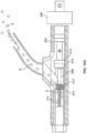
- Fig. 9E illustrates another variation where the catheter body 120 includes a set curve in an area that is adjacent to the cutting assembly 102.
- the outer sheath 122 can be made to be straight relative to the catheter body 120. Accordingly, advancement of the curved portion of the catheter body 120 out of the sheath 122 causes the catheter body 120 to assume its curved shape.
- the degree of articulation in such a case may be related to the degree of which the catheter body 120 is advanced out of the sheath 122.
- a separate torque control device to manually or automatically control the sweep of the catheter, independent of the axial control of the catheter insertion and the rotation control of the cutter within the housing.
- Automatic control may be performed open-loop by user entered settings and activating a switch, or with feedback control designed to further optimize cutting effectiveness, procedural efficiency, and safety.
- Example structures of how to lock the articulation of the sheath/catheter into place include a lockable collar, a stopper, and friction lock detect mechanisms with one or more springs, coils, or hinges.
- the vessel wall is protected by the expanded structure because the structure members (coil or struts) resist cutting by the atherectomy cutter, and are disposed in a way that they cannot invaginate into the cutter housing (and thereby be grabbed by the cutter). It is also possible to adjust the angle of the windows on the atherectomy catheter cutter housing so that they do not align with the struts or coils; the adjustment to orientation may be accounted for in the coil or strut design, in the cutter housing design, or both. Furthermore, the protective member can be relatively flexible and have a low profile (thin elements), so that it may be left in place as a stent.
Description
- The devices described below generally relate to treatment of occluded body lumens. In particular, the present devices relate to removal of the occluding material from the blood vessels as well as other body lumens.
- Atherosclerosis is a progressive disease. In this disease, lesions of the arteries are formed by accumulation of plaque and neointimal hyperplasia causing an obstruction of blood flow. Often plaque is friable and may dislodge naturally or during an endovascular procedure, leading to embolization of a downstream vessel.
- Endovascular clearing procedures to reduce or remove the obstructions to restore luminal diameter allows for increased blood flow to normal levels are well known. Removing the plaque has the effect of removing diseased tissue and helps to reverse the disease. Maintaining luminal diameter for a period of time (several to many weeks) allows remodeling of the vessel from the previous pathological state to a more normal state. Finally, it is the goal of an endovascular therapy to prevent short term complications such as embolization or perforation of the vessel and long term complications such as ischemia from thrombosis or restenosis.
- Various treatment modalities may help to accomplish treatment goals. In atherectomy, plaque is cut away, or excised. Various configurations are used including a rotating cylindrical shaver or a fluted cutter. The devices may include shielding by a housing for safety. The devices may also remove debris via trapping the debris in the catheter, in a downstream filter, or aspirating the debris. In some cases a burr may be used instead of a cutter, particularly to grind heavily calcified lesions into very small particle sizes. Aspiration may also be used with a burr-type atherectomy device.
- Balloon angioplasty is another type of endovascular procedure. Balloon angioplasty expands and opens the artery by both displacing the plaque and compressing it. Balloon angioplasty is known to cause barotrauma to the vessel from the high pressures required to compress the plaque. This trauma leads to an unacceptably high rate of restenosis. Furthermore, this procedure may not be efficient for treatment of elastic-type plaque tissue, where such tissue can spring back to occlude the lumen.
- When clearing such obstructions it is desirable to protect the vessel wall or wall of the body lumen being cleared and to debulk substantially all of a lesion. In additional cases, the procedure that clears obstructions may also be coupled with placement of an implant within the lumen. For example, it may be desirable to deploy a stent to maintain patency of a vessel for a period of time and/or to achieve local drug delivery by having the stent elute a drug or other bioactive substance.
- On their own, stents fail to perform well in the peripheral vasculature for a variety of reasons. A stent with the necessary structural integrity to supply sufficient radial force to reopen the artery often does not perform well in the harsh mechanical environment of the peripheral vasculature. For example, the peripheral vasculature encounters a significant amount of compression, torsion, extension, and bending. Such an environment may lead to stent failure (strut cracking, stent crushing, etc.) that eventually compromises the ability of the stent to maintain lumen diameter over the long-term. On the other hand, a stent that is able to withstand the harsh mechanical aspects of the periphery often will not supply enough radial force to open the vessel satisfactorily. In many cases, medical practitioners desire the ability to combine endovascular clearing procedures with stenting. Such stenting may occur prior to, after, or both before and after the endovascular clearing procedure.
- Accordingly, a need remains for devices that allow for improved atherectomy devices that clear materials from body lumens (such as blood vessels) where the device includes features to allow for a safe, efficient and controlled fashion of shaving or grinding material within the body lumen.
-
WO 96/29941 A1 -
US 5114399 A describes a surgical device which employs a catheter for removing obstructive material from the body cavity or luminal passage. The catheter has a blade subassembly on its distal tip for coring, homogenizing, diluting, and aspirating the obstructive material. -
WO 00/51504 A1 -
EP 0 373 927 A2 describes a medical device for clearing obstructions in body vessels which comprises a generally cylindrical housing having a rotary screw mounted therein. The screw co-operates with an inner leading edge of the housing to provide a scissor-like- cutting action. -
WO 92/14506 A1 -
US 5 728 129 A describes a distal atherectomy catheter for removing obstructions, plaque, stenosis, occlusions, or the like from an artery or coronary vessel. The catheter comprises a flexible, hollow catheter tube. A cutting element is located within a cylindrical housing mounted at the distal end of the catheter tube. The cutting element is connected to a hollow, flexible drive shaft concentrically located within the catheter tube. The cutting element housing includes a side opening window or port providing access to the interior of the housing. -
US 6 027 450 A describes a method and system for recanalizing a totally or near totally occluded body lumen such as an artery which has an elongated catheter shaft with means such as a cutting or ablating element at the distal end of the shaft to remove occluding material and with ultrasonic imaging means preferably located on the shaft proximal to the cutting or ablating element to allow the operator to maintain the radial position of the distal end of the catheter shaft within the body lumen so that no contact is made between the cutting or ablating means and the wall defining the body lumen. -
WO 2005/123169 A1 describes a vascular steerage access device having an elongate body and a steerable portion. The access sheath has an outside diameter sufficiently small so that it may be inserted into a vessel and a sufficient length to extend through a patient's circulatory system. The access sheath may have two internal lumens, a first lumen sized and configured as an access to a surgical site and a second lumen sized and configured to contain a tensioning device that, when acted upon, will deflect the steerable portion. - Devices and methods described herein provide improved means of clearing obstructions within body lumens, especially the vasculature. The features of the devices and methods allow for controlled removal of occlusive materials.
- The methods disclosed do not form part of the invention as claimed.
- The invention is defined by
independent claim 1 with further preferred embodiments defined by the dependent claims. In some variations, the devices also have features to convey the materials away from the operative site without the need to remove the devices from the body lumen. Additional examples include controlled rates of tissue removal as well as other safety features to prevent accidental cutting of the lumen wall. Although the devices and methods described herein discuss removal of materials from a blood vessel, in certain cases the devices and methods have applicability in other body lumens as well. It should be noted that the variations and features of the devices described below may be incorporated selectively or in combination with a basic device configuration that includes a flexible body having a cutter, where the cutter includes a housing and a cutter, where the housing and cutter are able to rotate relative to each other. Variations include a cutter that rotates within the housing, a housing that rotates about the cutter, and combinations thereof. - One variation of the device described herein includes a device configured to remove material from body structures. The device may be a vascular device and have the required structure and configuration to navigate tortuous anatomy. Alternatively, the device may be a cutter that has features that are desired when used in other parts of the anatomy.
- In any case, such a device includes a catheter body having a proximal end and a distal end, a cutter assembly located at the distal end of the catheter body, the cutter assembly comprising a housing having at least one opening and a cutter having at least one cutting surface configured to rotate relative to the housing, where movement of the cutting surface relative to the vessel removes occlusive material, a rotating shaft extending through the catheter body and coupled to the cutter, the shaft having a proximal end adapted to couple to a first rotating mechanism, and a deflecting member extending along the catheter body, such that the deflection member can cause deflection of the cutter assembly relative to an axis of the catheter.
- Devices of the present invention can also include multiple cutting surfaces. For example, the multiple cutting surfaces may cut tangential to a rotational direction of a cutting head, in a forward direction as the cutting assembly moves distally, and/or in a rearward direction as the cutting assembly is withdrawn proximally. The multiple cutting surfaces can be located on a single cutting head, or may be located on a housing of the cutting assembly. In certain variations of the device, a housing of the cutting assembly may be fully open at a distal end to expose a cutting head. Such a design can incorporate additional safety features to prevent excessive damage to vessel walls.
- Examples of the deflecting member may include steerable sheaths adapted to deflect in shape. The steerable sheath may be located internally to a catheter body of the device. Accordingly, the catheter body remains stationary while the sheath can rotate to move a cutting head in an arc about the target body passage.
- In some examples the steerable sheath may include a deflecting wire extending through a portion of the sheath, such that axial movement of the deflecting wire deflects the sheath. The deflecting wire can be affixed to the cutter assembly, to a portion of the catheter body that extends out of the deflecting sheath, or to other parts of the device as needed.
- The deflecting member can also include a pre-shaped mandrel, or tube where such features are slidable within or relative to the device to produce movement of the cutting head relative to an axis of the device. The devices described herein may have any number of features that allow for locking the device after it is articulated. This feature provides a consistent diameter when sweeping or navigating through the anatomy.
- As discussed herein, some examples of the devices have the ability to articulate. This articulation allows for steering the device to the target site as well as creating a sweeping motion of tissue removal. Accordingly, a deflectable sheath used in the device can be rotatable about the catheter body, or about an axis of the catheter.
- The devices described herein may have a cutter assembly having a portion of its housing having a curved surface and where the opening forms a plane across the curved surface such that as the cutting surface rotates across the opening, a portion of the cutting surface extends out of the housing through the opening. The cutter assembly may also have various other features as described below that improve the safety of the device as it is articulated while cutting. Furthermore the cutter may have a number of features to impel or drive cut tissue into the cutter assembly for eventual removal by one or more conveying members.
- As noted, the devices described herein may have one or more conveying members that convey materials and/or fluids through the device. Such a feature is useful to remove cut tissue and debris from the site during the procedure. In some variations, the device may include multiple conveyors to deliver fluids and remove debris. However, the devices of some examples may also have containers for use in capturing debris or other materials generated during the procedure.
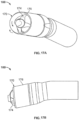
- Another feature for use in some examples is the use of a grinding burr rotatably coupled to a tip of the device. The burr can be useful to remove tissue that is otherwise not conducive to cutting with the cutter assembly.
- In another examples, the invention may comprise a device having a straightening tube, with a straight distal portion, a catheter body having a proximal end and a distal end, the catheter body having a flexible section located towards the distal end, such that when located in the straight distal portion of the straightening tube the flexible section is less curved, a cutter assembly located at the distal end of the catheter body, the cutter assembly comprising a housing having at least one opening and a cutter having at least one cutting surface configured to rotate relative to the housing, where movement of the cutting surface removes material, and a rotating shaft extending through the catheter body and coupled to the cutter, the torque shaft having a proximal end adapted to couple to a first rotating mechanism.
- In such a case, placement of the straight distal portion over the catheter allows for manipulation of the degree of curvature of the catheter. This feature allows for steering of the device.
- As described herein, such a device may have the ability to sweep over an arc to deliver a larger cutting diameter than the diameter of the cutter assembly.
- The devices described herein may use a guidewire for advancement through the body. In such cases the devices will have guidewire lumens located within or about the catheter. Alternatively, a guidewire section may be affixed to a portion of the device.
- Devices of the present invention typically include a torque shaft to deliver rotational movement to components in the cutter assembly. Alternatively, a torque shaft or other such assembly may be used to produce the sweeping action described herein. In any case, the torque shaft may include one or more lumens. Alternatively, the torque shaft may be a solid or hollow member. Variations of the torque shaft also include those aspects known in catheter-type devices such as counter-wound coils, stiffening members, etc. In some variations, the torque shaft may have the conveying member integrally formed about the exterior or an interior surface of the shaft. Alternatively, or in combination, the conveying member may be placed on (or within) the torque shaft as described herein.
- The examples also include various methods of debulking material within body structures. These structures include occluded blood vessels (whether partially or totally occluded), various organs, cavities within the body, or other body lumens.
- In one example a method includes inserting a catheter body having a cutter assembly within the blood vessel, rotating the cutter assembly to remove the material and form a first opening in the body lumen, deflecting the first cutter assembly relative to an axis of the catheter body, rotating the deflected catheter tip while rotating the cutter assembly to form a second opening in the body lumen where the second is larger than the first opening.
- The exemplary methods may include the use of any of the devices or features of the devices described herein. In some examples, the methods include circulating fluid for contrast to better visualize the obstruction.
- As noted herein, combinations of aspects of the devices, systems, and methods described herein may be combined as needed. Furthermore, combinations of the devices, systems and methods themselves are within the scope of the disclosure.
- The scope of the invention is solely defined by the appended claims.
-
-
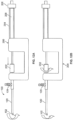
Fig. 1A illustrates an example of an atherectomy device; -
Fig. 1B shows an exploded view of the device ofFig. 1A ; -
Fig. 1C shows a cross sectional view of the cutting assembly; -
Fig. 2A shows alignment of the cutting edges with openings of a housing; -
Fig. 2B shows a side view of the cutting assembly demonstrating the secant effect; -
Fig. 2C illustrates a positive rake angle; -
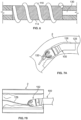
Figs. 3A-3B show an example of a shielded cutter having a plurality of front cutting surfaces, rear cutting surfaces, and fluted cutting surfaces; -
Figs. 4A-4B show another example of a shielded cutter having a plurality of front cutting surfaces and fluted cutting surfaces; -
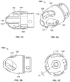
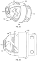
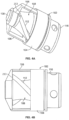
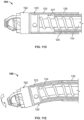
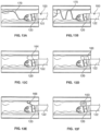
Figs. 5A-5D show a cutter assembly having an open ended housing according to the invention; -
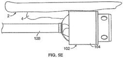
Fig. 5E shows a cutter assembly with the open ended housing according to the invention, removing material from a lumen wall; -
Fig. 6 shows a partial cross sectional view of a variation of a torque shaft having counter wound coils; -
Fig. 7A shows an example of a device configured for rapid exchange; -
Fig. 7B illustrates an example of centering a tip of a cutting assembly over a guidewire; -
Fig. 8A shows an example of a conveyor within the device; -
Fig. 8B shows a second conveyor within a torque shaft; -
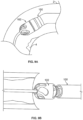
Fig. 9A illustrates articulation of a tip of the device; -
Fig. 9B-9D shows sweeping of the cutting assembly; -
Fig. 9E illustrates another example where the catheter body includes a set curve in an area that is adjacent to the cutting assembly; -
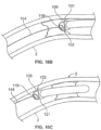
Fig. 10A shows an example of placement of housing windows to prevent damage to the vessel walls; -
Figs. 10B-10C shows an example of placement of features of the cutter assembly that prevent damage to the vessel walls; -
Figs. 11A-11C show an example of the device for articulating the cutting assembly; -
Figs. 12A-12B show a control system for rotating and articulating the cutter assembly; -
Fig. 12C shows an example of a perfusion port at a distal portion of the device; -
Fig. 12D shows a cross sectional view of a portion of the catheter hub mechanism that removes debris from the device; -
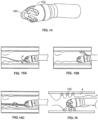
Figs. 13A-13F show additional examples of the device for articulating the cutting assembly; -
Fig. 14 shows an example of a device with a burr tip; -
Figs. 15A-15C provide examples of fluid delivery systems; -
Fig. 16 shows an example of the device placed within a stent or coil; -
Figs. 17A-17B show examples of devices for removing tissue from body lumens; -
Figs. 18A-18F show additional examples for centering devices within a lumen; -
Fig. 18G shows a balloon actuated device for treating occlusions; -
Figs. 19A-19C show a system for visualizing and crossing total occlusions; -
Figs. 20A-20C shows examples of devices described above for visualizing and crossing total occlusions; -
Figs. 21A-21B shows an example of crossing a total occlusion by advancing through layers of a vessel; -
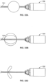
Figs. 22A-22F show examples of anchoring means on a guidewire for stabilizing devices. -
Fig. 1A illustrates an example of adevice 100. As shown thedevice 100 includes acutter assembly 102 affixed to a catheter orcatheter body 120. As shown, the catheter body may be optionally located within anouter sheath 122. It is noted that the cutter assembly shown in the figures exemplary purposes only. Any cutter assembly may be combined with the other aspects of the system. The variations of cutter assemblies discussed herein, can be combined with other aspects of the system. -
Fig. 1B illustrates an exploded view of thedevice 100 ofFig. 1A . As shown, in this variation thecutter assembly 102 includes ahousing 104 with a plurality ofopenings 106. However, additional cutter assembly configurations (as noted below) are combinable with the various aspects of the device configurations discussed herein. - In the illustrated variation, a
cutter 108 is located within thehousing 104. Thiscutter 108 includes one ormore flutes 110 each of which includes an edge or cuttingsurface 112. The cutter is coupled to arotating mechanism 150. In this variation the rotating mechanism couples to the cutter via atorque shaft 114 that transmits rotational energy from the rotating mechanism 150 (e.g., an electric, pneumatic, fluid, gas, or other motor) to thecutter 108. Variations of the devices include use of arotating mechanism 150 located entirely within the body of thedevice 100. In one variation, therotating mechanism 150 may be outside of the surgical field (i.e., in a non-sterile zone) while a portion of the device (e.g., the torque shaft - not shown) extends outside of the surgical field and couples to the rotating mechanism.Figure 1B also shows a variation of thedevice 100 as having a deflectingmember 124 where the deflecting member may be a tendon, pull wire, tube, mandrel, a tube or similar structure that causes a distal end of the catheter body to deflect (hereafter referred to as a "sweep sheath") or other such structure. As described in detail below, thedevices 100 can have deflecting members to articulate the cutting head and allow for a sweeping motion of cutting. - In another variation, the
device 100 may have a catheter body that comprises a soft or flexible portion. In one variation, this soft or flexible portion may be on a single side of thedevice 100 to allow flexure of thedevice 100 to articulate the cutting head. The flexure may be obtained with a curved sheath, mandrel, or other means as known to those skilled in the art. In the illustrated variation, the deflectingmember 124 comprises a sweep sheath. Thesweep sheath 124 has a curved or shaped distal portion, where the curve may be planar or the shaped portion may be a non-planar shape). The distal portion of the sweep sheath is more flexible than a proximal portion of the catheter body. As a result, when the sweep sheath assumes a somewhat straightened shape when in the proximal portion of the catheter body. However, the distal portion of the catheter body is more flexible than the sweep sheath. Accordingly, once the sweep sheath is advanced into the distal portion of the catheter, the catheter assumes the shape or profile of the sweep sheath. This is a way to deflect the cutter assembly off the axis of the catheter. Rotation of the sweep sheath causes the movement of the cutter assembly to sweep in an arc and create an opening larger than a diameter of the catheter itself. - The
device 100 may also include a vacuum source or pump 152 to assist in evacuation of debris created by operation of the device. Any number of pumps or vacuum sources may be used in combination with the device. For example, a peristaltic pump may be used to drive materials from the device and into a waste container.Fig. 1B also shows thedevice 100 coupled to afluid source 154. As with the rotating mechanism, the vacuum source and/or fluid source may be coupled to the device from outside the surgical field. - It may be advantageous to rotatably couple the torque shaft to the drive unit electromagnetically, without physical contact. For example, the
torque shaft 114 can have magnetic poles installed at the proximal end, within a tubular structure that is attached to the sheath around the torque shaft. The stationary portion of the motor can be built into a handle that surrounds the tubular structure. This allows the continuous aspiration through the sheath without the use of high speed rotating seals. - As shown in
Fig. 1C , in certain variations, thehousing 104 can have a distal nose with acenter lumen 142 for receiving amating piece 140 of thecutter 108. Such features assist in centering thecutter 104 concentrically inside thehousing 104. As noted below, variations of the devices include the addition of a burr element (as shown below) for grinding hard tissue such as calcified plaque. - The geometry of the
cutter 108 andhousing 104 can be used to tailor the desired degree of cutting. Thehousing 104 and orientation of theopenings 106 can be used to limit the depth of cutting by thecutter 108. In addition, the distal end of thehousing 104 may be domed shaped while the proximal end may have a cylindrical or other shape. For example, by creatinglarger windows 106 in the housing a larger portion ofcutter 108 may be exposed and the rate of cutting increased (for a given rotation speed). By placing the cuttingwindow 106 on a convex portion of the housing, the debulking effectiveness is much less sensitive to the alignment of the cutter housing to the lesion, than if the window were on the cylindrical portion of the housing. This is a key performance limitation of traditional directional atherectomy catheters. In addition, placement of the window on the convex portion of the housing creates a secant effect (as described below). -
Fig. 2A illustrates an additional variation of thedevice 100 where theopenings 106 may be helical slots that may or may not be aligned with the cutting surfaces 112 of thecutter 108. For aggressive cutting, theslots 106 and cuttingedges 112 are aligned to maximize exposure of the tissue to cutting edges. In other words, the cuttingedges 112 andopenings 106 are in alignment so all cuttingedges 112 are exposed at the same time to allow simultaneous cutting. Alternatively, alignment of the openings andedges 112 may be configured so that fewer than all the cutting edges 112 are exposed at the same time. For example, the alignment may be such that when onecutting edge 112 is exposed by anopening 106, the remainingcutting edges 112 are shielded within thehousing 104. Variations of such a configuration allow for any number of cutting edges to be exposed at any given time. - However, to even out the torque profile of the device when cutting, the
cutter 108 is configured such that the number edges/cuttingsurfaces 112 of theflutes 110 that are aligned with thehousing openings 106 does not vary throughout the rotational cycle. This prevents the catheter from being overloaded with torque spikes and cyclic torque variations due to multiple cutting edges/flutes engaging with tissue in synchrony. In other words, the length of the cuttingsurface 112 exposed through theopenings 106 of thehousing 104 remains the same or constant. - In the variation shown in
Fig. 2B , the cuttingsurface 112 is configured to capture debris as it cuts. Typically, thedevice 100 may be designed with a secant effect. This effect allows for a positive tissue engagement by the cutter. As the cutter rotates through the opening, the cutting edge moves through an arc, where at the peak of the arc the cutting edge slightly protrudes above a plane of the opening. The amount of positive tissue engagement can be controlled through selection of the protrusion distance through appropriate design of the housing geometry (for example, by a combination of location and size of the window and radius of curvature of the housing). As shown, the cuttingsurface 112 extends out of thehousing 104 through thewindow 106 as it rotates. This structure can also be designed to drive or impel the debris to the conveyingmember 118. In this case, theflutes 110 within thecutter 108 are helically slotted to remain in fluid communication with the conveyingmember 118. Variations of thedevice 100 can also include avacuum source 152 fluidly coupled to the conveyingmember 118. In order to improve the impelling force generated by the cutters, variations of the cutter havehelical flutes 110 andsharp cutting edges 112 that are parallel to each other and are wound from proximal to distal in the same sense as the rotation of the cutter. When the cutter rotates, it becomes an impeller causing tissue debris to move proximally for evacuation. - As shown in
Fig. 2C , variations of the device may have cuttingsurfaces 112 with positive rake angles α- that is the cutting edge is pointed in the same direction as that of the cutter rotation. This configuration maximizes the effectiveness of the impelling and cutting action (by biting into tissue and avoiding tissue deflection). The cutter is preferably made of hard, wear-resistant material such as hardened tool or stainless steels, Tungsten carbide, cobalt chromium, or titanium alloys with or without wear resistant coatings as described above. However, any material commonly used for similar surgical applications may be employed for the cutter. The outer surfaces of the proximal end of thecutter 108 are typically blunt and are designed to bear against thehousing 104. Typically, these surfaces should be parallel to the inner surface of the housing. -
Figs. 2A-2B also show a surface of thecutter 108 having a curved-in profile distally and is close to thehousing 104 surface. Note thathousing slots 106 with this curved profile allows thecutting edge 112 to protrude beyond the housing's outer surface. In other words, theopenings 106 form a secant on the curved surface of thehousing 104. Such a feature allows improved cutting of harder/stiffer material like calcified or stiff fibrous tissue where such tissue does not protrude into thehousing 104. - By controlling the number of cutting
edges 112 that are exposed throughopenings 106 in thehousing 104, it is possible to control the relative amount of cutting engagement (both length of cutting and depth of cut, together which control the volume of tissue removed per unit rotation of the cutter). These features allow independent control of the maximum torque load imposed on thedevice 100. By carefully selecting the geometry of the flutes and or cuttingedges 112 relative to theopenings 106 in the housing, it is possible to further control the balance of torque. For example, the torque load imposed on the device is caused by the shearing of tissue when the cutter edge is exposed by passing through the housing window. If all cutter edges simultaneously shear, as for example when the number of housing windows is an even multiple of cutter edges, the torque varies cyclically with rotation of the cutter. By adjusting the number of cutters and windows so one is not an even multiple of the other (for example, by using 5 windows on the housing and 4 cutting edges on the cutter), it is possible to have a more uniform torque (tissue removal from shearing action) during each cycle of the cutter. -
Fig. 3A illustrates another variation of acutter assembly 102.Fig. 3B shows a side view of thecutter assembly 102 ofFig. 3A . In this example, the cuttingassembly 102 includeslarger windows 106 to accommodate acutter 108 that includes a plurality of directional cutting surfaces 112, 213, 115. As thecutter 108 rotates within thehousing 104, thefluted cutting edge 112 cuts in a direction that is tangential to a rotational direction of thecutter 108. In other words, the fluted cuttingedges 112 cut material that is about the perimeter of thecutter 108 as it spins. Thecutter 108 also includes one or more forward and rearward cuttingsurfaces cutter 108 in the present example can include acutter 108 with one or two directional cutting surfaces. For example, the fluted cuttingedges 112 can be combined with either the forward 213 or rearward 115 cutting surfaces. The ability to debulk in a forward, rearward and rotational directions also reduces the chance that the cutter assembly deflects from stubborn or hard tissue. -
Figs. 4A and 4B show another variation of acutter assembly 102 having aforward cutting surface 213 on a front of thecutter 108. In this variation, thecutter housing 104 includes twolarge openings 106 that allow theforward cutting surface 213 to engage tissue when moved in a distal direction. Thecutter 108 also includes a plurality of fluted cutting edges 112. -
Figs. 5A and5C show another variation ofcutter assemblies 102. In these variations, thecutter assemblies 102 include acylindrical housing 104 containing acutter 108 therein. Thecutter 108 is exposed at adistal opening 117. Theedge 113 of thedistal opening 117 forms a forward cutting surface. Thehousing 104 rotates along with thecutter 108 to assist in removal of tissue. As noted above, theforward cutting surface 113 engages and removes tissue orplaque 4 when the device is advanced in a distal direction within abody lumen 2 as shown inFig. 5E . As discussed below, features of the device, including aguidewire 128 assist in preventing the device from excessively cutting thelumen wall 2. - The
housing 104 can be linked to thecutter 108 in a variety of ways as is well understood by those skilled in the art. For example thehousing 104 can be directly linked or affixed to thecutter 108 so that both rotate together. Alternatively, thehousing 104 can be geared to rotate faster or slower than thecutter 108. According to the invention, the gearing can be chosen to permit thehousing 104 to rotate in an opposite direction than thecutter 108. -
Figs. 5B and5D show respective side views ofFigs. 5A and 5B . As shown, inFig. 5B , thecutter 108 can protrude partially from theforward cutting surface 113 of thehousing 104.Fig. 5C shows a variation where thecutter 108 extends further from thehousing 104 than the variation shown inFig. 5B . Variations of the invention includecutters 108 that are totally recessed within thehousing 108 or those having their entirefluted cutting edge 112 exposed distal to the cuttingsurface 113. In any case, thefluted cutting edge 112 impels tissue debris back into the catheter. The outer diameter of the housing, proximal to theforward cutting surface 113 can be smooth to protect the lumen wall from the cutting action of the cutting edges. When the cuttingassembly 102 is deflected, the outer diameter of thehousing 102 becomes flush against the lumen wall and prevents the cutting edges from engaging the vessel wall (as shown inFig. 5E ). As the cutter assembly is advanced forward, it removesplaque 4 protruding from thelumen 2 wall and tissue debris is impelled backwards by thefluted edge 112 of thecutter 108. -
Figs. 5A to 5D also show acutter assembly 102 having ablunt bumper 119 at the very tip of thecutter 108 that acts as a buffer to prevent accidental cutting into the guidewire or the vessel wall given the cutter assemblies' open distal design. In additional variations, thehousing 104 could be expandable (such as a basket or mesh). As thecutter 108 gyrates inside the housing, the housing expands to cut a larger diameter. - The shielded atherectomy catheters described herein can perform biopsies, tumor removal, fibroid treatment, debulking of unwanted hyperplastic tissues such as enlarged prostate tissue, or other unwanted tissue such as herniated spinal disc material. The flexible, low profile catheter allows for ease of access to the treatment site and minimizes trauma or collateral damage to surrounding healthy tissue. With the continuous aspiration capability, contamination of the surrounding tissue during device introduction, treatment and removal is reduced or even eliminated. In addition, aspiration can be used to transfer biopsy tissue samples to outside the body for testing with the catheter remains in situ. This helps the physician make real time decision in advancing treatment of malignant tissue. The shield on the cutter assembly maintains controlled excision of tissue by limiting the depth of cutter engagement and thereby prevents the physician from inadvertently cutting into healthy surrounding tissue. The tip steering capability of the cutter allows the physician to direct the cutter towards desired site of tissue removal and minimizing collateral tissue damage. Finally, by deflecting the cutter and rotating the deflection to sweep in an arc, the catheter can excise large tumors or tissue lumps larger than the diameter of the catheter. Thus, excision of large tumors can be achieved through a small access channel and thereby minimizing trauma to the patient.
- The construction of the cutting assembly can provide for additional modes of energy delivery. For example, the catheter excises tissue in vascularized regions excessive bleeding can occur (e.g., lung biopsy and excision). Accordingly, energy can be delivered to the target site via a conductive cutter assembly (i.e. shield or even cutter). Sound energy (ultrasound), electrical energy (radio frequency current), or even microwaves can be used for this purpose. These energy sources delivered through the cutter can also be used to denature tissue (collagen), shrink tissue, or ablate tissue.
- The cutter assembly can be made from a variety of materials. For example, the housing is preferably made of a strong, wear resistant material such as hardened steels, cobalt chromium, carbides or titanium alloys with or without wear resistant coatings like TiNi. In particular the use of coatings will allow the use of tool steels which, unless coated, do not have acceptable corrosion resistance and biocompatibility. The cutter can be fabricated from steel and can be coated with a titanium nitride. Alternatively, the cutter can be fabricated from a tungsten carbide material.
- Coatings can be applied to the moving components in the catheter to reduce friction. In one example, the sheaths and the torque shaft are coating with a hydrophilic coating (polyvinyl alcohol) to reduce friction between the moving components in the catheter. The coatings can also be hydrophobic (e.g. parylene, PTFE). The coatings can be impregnated with heparin to reduce blood clotting on surface during use.
-
Fig. 6 shows a partial sectional view of an example of atorque shaft 114 that is coupled to a cutter assembly. To aid in removal of materials, the torque shaft can be a set of counter-wound coils, with the outer coil wound at the proper (greater) pitch to form the conveyingmember 118. Winding the coils counter to each other automatically reinforces thetorque shaft 114 during rotation. Alternatively, thetorque shaft 114 may be made out of a rigid plastic, rendered flexible by incorporation of a conveyingmember 118. Although the shaft may be fabricated from any standard material, variations of the shaft include a metal braid embedded in polymer (PEBAX, polyurethane, polyethylene, fluoropolymers, parylene) or one or more metal coils embedded in a polymer such as PEBAX, polyurethane, polyethylene, fluoropolymers or parylene. These constructions maximize torsional strength and stiffness, as well as column strength for "pushability", and minimize bending stiffness for flexibility. Such features are important for navigation of the catheter through tortuous vessels but allow for smooth transmission of torque over the long length of the catheter. In the multi-coil construction, the inner coil should be wound in the same sense as that of the rotation so that it would tend to open up under torque resistance. This ensures that the guidewire lumen remains patent during rotation. The next coil should be wound opposite the inner to counter the expansion to keep the inner coil from binding up against the outer catheter tube. -
Fig. 6 also shows atorque shaft 114 having acentral lumen 130. Typically the lumen will be used to deliver a guidewire. In such cases, the central lumen may be coated with a lubricious material (such as a hydrophilic coating or Parylene) or made of a lubricious material such as PTFE to avoid binding with the guidewire. However, in some variations a guidewire section is affixed to a distal end of the housing. Moreover, the central lumen of thetorque shaft 114 may also be used to deliver fluids to the operative site simultaneously with the guidewire or in place of the guidewire. -
Fig. 7A illustrates a variation of adevice 100 configured for rapid exchange. As shown, thedevice 100 includes a short passage, lumen, orother track 136 for the purpose of advancing thedevice 100 over aguidewire 128. However, thetrack 136 does not extend along the entire length of thedevice 100. Moreover, an additional portion of thetrack 136 may be located at a distal end of the catheter to center aguidewire 128. - This feature permits rapid decoupling of the
device 100 and guidewire 128 by merely holding the guidewire still and pulling or pushing thecatheter 100 over the guidewire. One benefit of such a feature is that theguidewire 128 may remain close to the site while being decoupled from thedevice 100. Accordingly, the surgeon can advance additional devices over the guidewire and to the site in a rapid fashion. This configuration allows for quick separation of the catheter from the wire and introduction of another catheter over the wire since most of the wire is outside of the catheter. - As shown in
Fig. 7B , centering the tip of the cuttingassembly 102 over aguidewire 128 improves the control, access and positioning of the cuttingassembly 102 relative to a body lumen orvessel 2. To accomplish this, the cuttingassembly 102 can have a central lumen to accommodate aguidewire 128. Variations of thedevice 100 includes a central guidewire lumen runs the length of the catheter through all central components including the torque shaft and the cutter. As noted above, aguidewire 128 can be affixed to thehousing 104 or other non-rotational component of the cuttingassembly 102. In such a case, theguidewire 128 may preferably be a short segment that assists with navigation of the device through an occluded portion of a body lumen. However, thedevices 100 can also operate without a guidewire since the head is steerable like a guidewire. -
Fig. 8A illustrates a partial cross-sectional view of another variation of adevice 100. As shown, this variation of thedevice 100 includes aconveyor member 118 located within thedevice 100 and located on an exterior surface of atorque shaft 114. Theconveyor member 118 may be an auger type system or an Archimedes-type screw that conveys the debris and material generated during the procedure away from the operative site. In any case, the conveyingmember 118 will have a raised surface or blade that drives materials in a proximal direction away from the operative site. Such materials may be conveyed to a receptacle outside of the body or such materials may be stored within thedevice 100. In one variation, thetorque shaft 114 and conveyingmember 118 extend along the length of the catheter. - In some variations, the conveying
member 118 may be integral to the shaft 114 (such as by cutting the conveyingmember 118 into thetorque shaft 114 or by extruding thetorque shaft 114 directly with a helical groove or protrusion. In an additional variation as shown inFig. 8B , an additional conveyingmember 118 may be incorporated on an inside of the torque shaft, where the internal conveying member is wound opposite to that of the external conveyingmember 118. Such a configuration allows for aspiration and debris (via the external conveying member 118) and infusion (via the internal conveying member 118). Such a dual action can enhance the ability to excise and aspirate plaque by: (1) thinning the blood, whether by viscosity alone or with the addition of anti-coagulants such as heparin or warfarin (cumadin), and/or anti-platelet drugs such as Clopidegrel, (2) improving the pumpability (aspirability) of the excised plaque by converting it into a solid-liquid slurry that exhibits greater pumping efficiency, and (3) establishing a flow-controlled secondary method of trapping emboli that are not sheared directly into the housing, by establishing a local recirculation zone. - As noted above, the conveying
member 118 can be wound in the same directional sense as thecutter 108 and in the same direction of rotation to effect aspiration of tissue debris. The impeller action of thecutter 108 moves the tissue debris from inside thehousing 104openings 106 into the torque shaft. The pitch of the cutting edges 112 may be matched in to that of the conveyingmember 118 to further optimize aspiration. Alternatively, the pitch of the conveyingmember 118 may be changed to increase the speed at which material moves once it enters the conveyingmember 118. As discussed herein, debris can be evacuated outside the body by the conveyingmember 118 action along the length of the catheter and with or without supplement of thevacuum 152 pump connected to the catheter handle. Alternatively, the debris may be accumulated in a reservoir within the device. - The device may also include a
ferrule 116, as shown inFig. 1B , that permits coupling of thecatheter body 120 to thecutter assembly 102. Theferrule 116 may serve as a bearing surface for rotation of thecutter 108 within thecutter assembly 102. In the illustrated variation, thetorque shaft 114 rotates inside theouter catheter body 120 andferrule 116 to rotate the cutter and pull or aspirate tissue debris in a proximal direction. The clearance between the catheter tube and conveyingmember 118, as well as the pitch and thread depth of the conveyingmember 118, are chosen to provide the desired pumping effectiveness. - In one variation of the device, the
housing 104 is connected to thecatheter body 120 via theferrule 116 and thus is static. Thecutter 108 rotates relative to thehousing 104 such that the cuttingsurface 112 on thecutter 108 shears or cleaves tissue and trap the tissue inside thehousing 104 so that it can be evacuated in a proximal direction using the impeller action of the helical flutes and vacuum from the torque shaft. In alternate variations, such as where the housing includes a forward cutting surface, thehousing 104 rotates as well as the cutter. Accordingly, the ferrule can serve as a bearing surface for both the housing and cutter. - The
ferrule 116 can have a distal bearing surface to bear against the proximal surface of thecutter 108 and keeps the cutter axially stable in thehousing 104. In cases where the housing is stationary, theferrule 116 can be rigidly bonded/linked to thehousing 104 using solder, brazing, welding, adhesives (epoxy), swaging, crimped, press-fit, screwed on, snap-locked or otherwise affixed. As shown, theferrule 116 can have holes or other rough features that allow for joining with the catheter body. While adhesives and heat fusing may be employed in the construction, such features are not required. Often adhesives are unreliable for a small surface contact and heat fusing can cause the tube to degrade. The use of amechanical locking ring 126 allows the cuttingassembly 102 to be short. Such a feature is important for maximizing the flexibility of the distal section of the catheter as it is required to navigate tortuosity in blood vessels. - In another examples,
devices 100 can be adapted to steer to remove materials that are located towards a side of the body passage. Such devices may include a deflecting member that permits adjusting the orientation or offset of thecutter assembly 102 relative to a central axis of the device. InFig. 1B , the deflecting member comprises acatheter 122 with a sweep sheath deflecting member 132 (however, the deflecting member can be a tendon, wire, tube, mandrel, or other such structure.) As described herein, other variations are within the scope of the device. -
Fig. 9A illustrates an example of a variation of adevice 100 equipped to have an articulating orsteerable cutter assembly 102. The ability to steer the tip of thedevice 100 is useful under a number of conditions. For example, when debulking an eccentric lesion as shown, the cuttingassembly 102 should be pointed towards the side of thevessel 2 having the greater amount ofstenotic material 4. Naturally, this orientation helps prevent cutting into the bare wall/vessel 2 and focuses the cutting onstenotic tissue 4. As shown in when in a curved section of thevessel 2, without the ability to steer, the cuttingassembly 102 would tend to bias towards the outside of the curve. Steering allows the cuttingassembly 102 to point inward to avoid accidental cutting ofvessel wall 2. - The ability to steer the
device 100 also allows for a sweeping motion when cutting occlusive material.Fig. 9B shows the rotation of the cuttingassembly 102. As shown inFig. 9C , when the cuttingassembly 102 deflects relative to the axis of the catheter, rotation of the deflectedportion 102 creates a sweeping motion. It is noted that rotation or articulation of the cutting assembly also includes rotation or articulation of the catheter to allow the cutting assembly to deflect relative to an axis of the catheter.Fig. 9D shows a front view taken along an axis of the vessel to illustrate the sweeping motion causing the cuttingassembly 102 to "sweep" over a larger region than the diameter of the cutting assembly. In most cases, when articulated, the device will be rotated to sweep over an arc or even a full circle. The rotation of the cutter may or may not be independent of the rotation of the device. A user of the device may couple the sweeping motion of the cutting assembly with axial translation of the catheter for efficient creation of a larger diameter opening over a length of the occluded vessel. The combination of movement can be performed when the device is placed over a guidewire, for example by the use of a lead screw in the proximal handle assembly of the device. In another examples of the devices described herein, the angle of articulation may be fixed so that the device sweeps in a uniform manner when rotated. - A number of variations to control the deflection of the
device 100 are described herein. For example, as shown inFig. 6 thesheath 122 itself may have a pre-set curve. In such a case, the area of thecatheter body 120 adjacent to the cuttingassembly 102 will be sufficiently flexible so as to assume the shape of thecurved sheath 122. -
Fig. 9E illustrates another variation where thecatheter body 120 includes a set curve in an area that is adjacent to the cuttingassembly 102. In this case, theouter sheath 122 can be made to be straight relative to thecatheter body 120. Accordingly, advancement of the curved portion of thecatheter body 120 out of thesheath 122 causes thecatheter body 120 to assume its curved shape. The degree of articulation in such a case may be related to the degree of which thecatheter body 120 is advanced out of thesheath 122. - In addition, the shape of the
housing 104 as well as the location of thewindows 106 can be chosen so that when thedevice 100 is substantially aligned with the lesion, or engages it at less than some critical attack angle, it will cut effectively. However, when pivoted at an angle greater than the critical angle, the cutting edges or grinding element will not engage the lesion as shown inFig. 10A . This means that at large deflections, as the catheter tip approaches the vessel wall, it automatically reduces its depth of cut and ultimately will not cut when the critical angle is exceeded. For example, the cutter distal tip is blunt and does not cut. As the catheter tip is deflected outward, the blunt tip contacts the vessel and keeps the cutting edges proximal to the tip from contacting the vessel wall. Also the wire in combination with the device can also act as a buffer to prevent the cutting edges from reaching the vessel. -
Figs. 10B and 10C show a cutter assembly design that is specialized for forward cutting. This particular variation includes an open ended housing where the cutter extends from the housing (as shown above). However, ablunt bumper 119 at the tip of thecutter 108 acts as a buffer to prevent accidental cutting into theguidewire 144 or excessively into thelumen wall 2. In addition, this design can optionally incorporate astatic housing portion 121 on a back end of thecutter assembly 102 that partially shields the cutter from deep side cuts into thelumen wall 2. - As mentioned above, variations of the
device 100 allow directional control of the cuttingassembly 102. In those variations where a slidable, torqueable sheath advances relative to the catheter body 122 (either external or internal to the catheter body) that can be flexed at the distal end. With the sheath flexed the catheter tip is pointed in the direction of the flex and the degree of bias is affected by the amount of flex on the sheath. The sheath can be rotated about the catheter or vessel long axis to change the direction of the cutting assembly. Also as noted above, this rotation can also effect a sweep of the cuttingassembly 102 in an arc or a circle larger than a diameter of the cutter 102 (e.g. seeFig. 9D ). Such a feature eliminates the need to exchange the device for a separate cutting instrument having a larger cutting head. Not only does such a feature save procedure time, but the device is able to create variable sized openings in body lumens. - As shown in
Fig. 11A , the tension on aslidable wire 132 in the wall of thesheath 122 can cause flexure of thesheath 122. Compression of the wire can also cause flexure of the sheath in the opposite direction. In one variation, thesheath 122 can be attached to thehousing 104 of the cuttingassembly 102. Since thehousing 104 is rotatable relative to thecutter 108 and thetorque shaft 114, thesheath 122 can rotate independently of thetorque shaft 114 andcutter 108 to either sweep the cuttingassembly 102 or to change direction of the articulatedcutting assembly 102 at an independent rate. - In another variation of the
device 100, as shown inFig. 11B , a preshaped curved wire ormandrel 134 can be advanced in a lumen in either thesheath 122 orcatheter 120. As themandrel 134 advances, the device takes the shape as shown inFig. 11C . - In yet another variation, the catheter tip and cutting assembly can be articulated in different directions and swept through an arc by having a series of sliding pull wires running through side lumens in the sheath. The pull wires attach to the cutter assembly. By cycling tension on the pull wires sequentially on the proximal control with such mechanism as a cam, the deflected tip can be swept in an arc.
-
Figs 11D to 11E illustrate a variation of adevice 100 having a pre-shaped sweep sheath for a deflectingmember 124 located in a space between thecatheter 120 and thetorque shaft 114. In this variation, thecatheter 120 includes a flexibledistal portion 123 and a relatively stifferproximal portion 125. When thesweep sheath 124 is located within the stifferproximal portion 125 of the catheter lumen thesweep sheath 124 straightens. To articulate thecutter assembly 102, the operator advances thesweep sheath 124 as shown byarrow 127 such that thesweep sheath 124 locates within the flexibledistal portion 123 of thecatheter 120. As a result, and as shown inFig. 11B , thesweep sheath 124 causes articulation of thecutter assembly 102. Thesweep sheath 124 is rotatable as well as axially moveable within thecatheter 124. As a result, rotation of thesweep sheath 124 sweeps thecutter assembly 102 in an arc as discussed above. - As shown, the
catheter body 120 remains stationary while theinner sweep sheath 124 rotates to move the cuttingassembly 102 in an arc or orbit within the lumen. Theouter catheter 120 body provides a static linkage between the cutter assembly and the deflection control assembly. The outer sheath is preferably composed of a metal braid sandwiched in a polymeric matrix of such materials as polyethylene (PE), fluoro-polymer (PTFE), nylon, polyether-block amide (PEBAX), polyurethane, and/or silicone. The sheath is stiffer proximally than distally. This can be achieved by using softer grades of polymers distally and/or having no metal braid distally. -
Fig. 12A and 12B illustrate one variation of a control system or fixture. As shown, thecontrol system 200 includes asweep control knob 202 coupled to a sweep sheath (not illustrated.) Thesweep control knob 202 can slide axially and rotate independently relative to theouter catheter 120 and the torque shaft (not shown). Again, the sweep sheath can be composed of a metal braid sandwiched in a polymeric matrix of such materials as polyethylene (PE), fluoro-polymer (PTFE), nylon, and/or polyether-block amide (PEBAX), polyurethane, and/or silicone. The sweep sheath can also be made of counter wound metal coils. Its distal end is curved and is preferably made of a material that can withstand high degree of flex and retain its curved shape. Such material may include polymers such as PE, nylon, Polyetheretherketone (PEEK), Nickel Titanium (Nitinol), or spring steel. - To allow the cutter assembly to be straight and undeflected 102, the sweep sheath is withdrawn proximally by the
sweep control knob 202. This causes the curved or shaped section of the sweep sheath to retract within the stiff portion of theouter catheter 120. As shown inFig. 12A , distal movement of thesweep control knob 202 advances the sweep sheath to deflect the catheter tip. The degree of the deflection is controlled by the amount the sweep sheath is advanced. The more the curve of the sweep sheath protrudes distal to the stiff section of the outer sheath, the more the catheter deflects. - As shown in
Fig. 12B , thesweep control knob 202 can be rotated to sweep the cuttingassembly 102 in an arc manner. Although sweeping of the cuttingassembly 102 can occur via manual operation. Variations of the device include sweep sheaths that can be selectively coupled to a motor to activate an automated rotation. This allows the physician to have a smooth, continuous, automated means to sweep the cutter without any manual effort. -
Figs. 12A and 12B also show thecatheter 120 as having aflush port 129. Theflush port 129 provides a means for injecting a fluid such as heparinized saline or any other medicine into thecatheter body 120 to keep blood and tissue debris from clogging the space between components in the device. Theflush port 129 can also help lubricate moving components within the device. One desirable fluid path is along the length of the catheter in the space between thecatheter body 120 and sweepsheath 124. Drugs or fluids can be introduced via theflush port 129 for flow out of one ormore openings 131 near the catheter tip or cuttingassembly 102. In some variations, it may be desirable to place aflush opening 131 at an "elbow" of thecatheter body 120 as shown inFig. 12C . During use of the catheter the tip is deflected, the "elbow" always contacts the luminal surface. Drugs flushing out this elbow can then infuse into the vessel wall. Using a stenosis-inhibiting drug like paclitaxel or rapamycin could help prevent restenosis after the atherectomy procedure. - Turning now to a variation of the
catheter 100 andcontrol system 200, the entire system is arranged from distal to proximal with acutter assembly 102, acatheter body 120, aflush port 129, acontrol system 200 for tip deflection and sweep control, ahub 204 or other connection for providing aspiration of the cut materials as well as adrive gear 206 to turn the torque shaft and cutter. Thegear 206 is connected to arigid drive shaft 208 encased within thehub 204 as shown inFig. 12D . Thedrive shaft 208 can take a form of a hollow tube with a central lumen for passage of the guidewire and is centered within a lumen in thehub 204 and fixed axially by a pair ofbearings 210. Aseal 212 adjacent to thebearing 210 prevents aspirated tissue debris from leaking proximally through thebearing 210. Atransfer propeller 212 is rigidly attached to the distal portion of thedrive shaft 208 to pumpaspirated tissue debris 8 from the catheter out into an attached aspiration reservoir. Thedrive shaft 208 is connected toflexible torque shaft 114 that extends the length of the catheter body for the purpose of transfer torque from the drive shaft to the cutter. As noted above, thetorque shaft 114 has helical grooves on its outer diameter and central guidewire lumen. During a procedure run, a motor drives thegear 206 to rotate. This causes rotation of thedrive shaft 208, thetransfer propeller 212, thetorque shaft 114, and the cutter (not shown) all in the same rotational sense. Thus the cutter assembly effectively cuts plaque and drives the debris back into the helical groove on thetorque shaft 114. The rotating helical grooves winds the debris back into thehub 204, which is then transferred to the aspiration reservoir by thetransfer propeller 212. Thepropeller 212 can take the form of a screw or a series of circumferentially arranged angled fan blades. The cutter is preferably rotated at a speed of 10,000-25,000 rpm. An alternative design would have the aspiration reservoir built into the hub of the catheter. -
Figs. 13A to 13F illustrate additional mechanisms for flexing thedevice 100. Such mechanisms can include side balloons 160, meshes,wire loops 164, coils 166, and arms ormandrels 168 and other such structures. These features can be incorporated intocatheter body 120 itself or into thesheath 122. If located in thecatheter body 122, the entire catheter can be rotated to steer the tip in different directions. A curved orhelical guidewire 170 can also be used to effect the flexion of the catheter tip as shown inFigs. 13A to 13F . The wire can also be actively flexed to control the degree of catheter flexion. All of these deflecting mechanisms can cause the catheter to be deflected in one plane or it can be deflected in three dimensions. The curve on the wire can be in one plane or in 3 dimensions. The sheath can be flexed in one plane or 3 dimensions. Another way to achieve flexion at the distal tip of the catheter is to only partially jacket the distal end with one or more polymers. A bevel at the distal end and/or varying combinations of jacketing and polymers can be used to change the position of the moment arm. This changes the flexibility of the distal end and allows proper deflection. - In addition to providing a means for deflecting the catheter, and allowing the user to sweep the distal tip to engage the lesion as desired, it is also possible to link a separate torque control device to manually or automatically control the sweep of the catheter, independent of the axial control of the catheter insertion and the rotation control of the cutter within the housing. Automatic control may be performed open-loop by user entered settings and activating a switch, or with feedback control designed to further optimize cutting effectiveness, procedural efficiency, and safety. Example structures of how to lock the articulation of the sheath/catheter into place include a lockable collar, a stopper, and friction lock detect mechanisms with one or more springs, coils, or hinges.
- Additional components may be incorporated into the devices described herein. For example, it can be desirable to incorporate transducers into the distal region of the catheter to characterize the plaque or to assess plaque and wall thickness and vessel diameter for treatment planning; also transducers may be desired to indicate the progression of debulking or proximity of cutter to vessel wall. For example, pressure sensors mounted on the catheter housing can sense the increase in contact force encountered in the event that the housing is pressed against the vessel wall. Temperature sensors can be used to detect vulnerable plaque. Ultrasound transducers can be used to image luminal area, plaque thickness or volume, and wall thickness. Optical coherence tomography can be used to make plaque and wall thickness measurements. Electrodes can be used for sensing the impedance of contacted tissue, which allows discrimination between types of plaque and also vessel wall. Electrodes can also be used to deliver impulses of energy, for example to assess innervation, to either stimulate or inactivate smooth muscle, or to characterize the plaque (composition, thickness, etc.). For example, transient spasm may be introduced to bring the vessel to a smaller diameter easier to debulk, then reversed either electrically or pharmaceutically. Electrical energy may also be delivered to improve the delivery of drugs or biologic agents, by causing the cell membrane to open in response to the electric stimulation (electroporation). One method of characterization by electrical measurement is electrical impedance tomography.
- As shown in
Fig. 14 , acutter assembly 102 can also have a burr protruding out its nose. Although theburr 180 may have any type of abrasive surface, in one variation, this burr is blunt and has fine grit (such as diamond grit) to allow for grinding of heavily calcified tissue without injuring adjacent soft tissue. This combination of a burr and cutter allow the distal assembly to remove hard stenotic tissue (calcified plaque) using the burr while the sharp-edged shaving cutter removes softer tissue such as fibrous, fatty tissue, smooth muscle proliferation, or thrombus. In variations, the burr can also have helical flutes to help with aspiration, or the burr can be incorporated to a portion of the cutting edge (for example, the most distal aspect of the cutter). - Infusing solutions (flush) into the target treatment site may be desirable. Infused cool saline can prevent heating of blood and other tissue, which reduces the possibility of thrombus or other tissue damage. Heparinized saline can also prevent thrombus and thin out the blood to help maximize effectiveness of aspiration. The flush can also include drugs such as Clopidegrel, Rapamycin, Paclitaxel or other restenosis-inhibitors. This may help to prevent restenosis and may result in better long term patency. The flush may include paralytics or long-acting smooth muscle relaxants to prevent acute recoil of the vessel.
Figs. 15A-15C illustrate variations of flushing out thedevice 100. The flush can be infused through the guidewire lumen (Fig. 15A ), a side lumen in the catheter shaft (Fig. 15B ) or tube, the space between the flexing sheath and the catheter and/or the sideports in the guidewire (Fig. 15C ). Flush can come out of a port at the distal end of the cutter pointing the flush proximally to facility aspiration. Alternatively, by instilling the flush out the distal end of the cutter housing over the rounded surface, the flow may be directed rearward by the Coanda effect. The restenosis-inhibitors can be carried by microcapsules with tissue adhesives or vecro-like features on the surface to stick to inner vessel surface so that the drug adheres to the treatment site, and to provide a time-re]ease controlled by the resorption or dissolving of the coating to further improve efficacy. Such velcro-like features may be constructed with nanoscale structures made of organic or inorganic materials. Reducing the volume of foreign matter and exposing remaining tissue and extracellular matrix to drugs, stimulation, or sensors can make any of these techniques more effective. - Another way to infuse fluid is to supply pressurized fluid at the proximal portion of the guidewire lumen (gravity or pressure feed) intravenous bag, for example. A hemostatic seal with a side branch is useful for this purpose; tuohy-borst adapters are one example of a means to implement this.
- Balancing the relative amount of infusion versus fluid volume aspirated allows control over the vessel diameter; aspirating more fluid than is instilled will evacuate the vessel, shrinking its diameter, and allow cutting of lesion at a greater diameter than the atherectomy catheter. This has been a problem for certain open cutter designs that use aspiration, because the aggressive aspiration required to trap the embolic particles evacuates and collapses the artery around the cutter blades; this is both a performance issue because the cutter can bog down from too high torque load, and the cutter can easily perforate the vessel. The shielded design described here obviates both problems, and further requires less aggressive aspiration to be effective, giving a wider range of control to the user.
- The devices of the some examples may also be used in conjunction with other structures placed in the body lumens. For example, as shown in
Fig. 16 , one way to protect the vessel and also allow for maximum plaque volume reduction is to deploy a protective structure such as a stent, thin expandable coil or anexpandable mesh 182 within a lesion. As this structure expands after deployment, the thin wire coil or the struts push radially outward through the plaque until it becomes substantially flush with the vessel wall. This expansion of thin members requires minimal displacement of plaque volume and minimizes barotrauma produced in balloon angioplasty or balloon expanded stent delivery. Once the protective structure has expanded fully, atherectomy can be performed to cut away the plaque inside to open up the lumen. The vessel wall is protected by the expanded structure because the structure members (coil or struts) resist cutting by the atherectomy cutter, and are disposed in a way that they cannot invaginate into the cutter housing (and thereby be grabbed by the cutter). It is also possible to adjust the angle of the windows on the atherectomy catheter cutter housing so that they do not align with the struts or coils; the adjustment to orientation may be accounted for in the coil or strut design, in the cutter housing design, or both. Furthermore, the protective member can be relatively flexible and have a low profile (thin elements), so that it may be left in place as a stent. Because the stent in this case relies mainly upon atherectomy to restore lumen patency, it may be designed to exert far less radial force as it is deployed. This allows usage of greater range of materials, some of which may not have as high of stiffness and strength such as bioresorbable polymers and metal alloys. Also, this allows a more resilient design, amenable to the mechanical forces in the peripheral arteries. It also minimizes flow disruption, to minimize hemodynamic complications such as thrombosis related to the relatively low flows found in the periphery. It is also possible to perform atherectomy prior to placing the protective structure, whether or not atherectomy is performed after placing the structure. - Additional variations of systems include
devices 100 having a cuttingassembly 170 comprising spinning turbine-like coring cutter 172 as shown above and as shown inFig. 17A. Fig. 17B shows a side view of thecoring cutter 170. In use, the coring cutter can be hydraulically pushed to drive the sharp edge through tissue. The turbine like cutters hashelical blades 174 on the inside of the sharp cylinder housing 176 (shell). Thecoring cutter 170 may also have spokes or centeringdevices 184 as shown to inFigs. 18A to 18F center the shell about the guidewire. This helps to keep the cut of the plaque centered about the vessel wall for safety. The spokes also act as an impeller to pull stenotic tissue back and this helps to drive the cutter forward as well as achieve aspiration to minimize embolization. In the hydraulically driven cutter design, ananchor 186 is deployed in tissue and is connected to abackstop 192. A balloon orhydraulic chamber 188 is then pressurized to expand and pushes thecutting blade 190 forward through the lesion (seeFig. 18G ). One advantage of this approach may be that the technique is similar to angioplasty (which involves pumping up a balloon with an endoflator). One means of anchoring is to use an anchoring guidewire, for example, a guidewire with an inflatable balloon to be placed distal to the atherectomy catheter. Alternatively, the technique of anchoring distally can be used with the previously described torque shaft driven atherectomy catheter. - It is also possible to use the devices and methods described here to restore patency to arterial lesions in the coronary circulation and in the cerebrovascular circulation, both by debulking de novo lesions and by debulking in stent restenosis.
- The devices and methods described herein also work particularly well in lesions that are challenging to treat with other methods: at bifurcations, in tortuous arteries, and in arteries which are subject to biomechanical stresses (such as in the knee or other joints).
- In a further variation of the devices described here, the motor drive unit may be powered by a controller that varies the speed and torque supplied to the catheter to optimize cutting efficiency or to automatically orbit the cutter using variable speed with a fixed flexible distal length of catheter (or providing further orbiting control by controlling the length of the distal flexible section of the catheter).
- It is also possible to use feedback control to operate the catheter in a vessel safe mode, so that the rate of cutting is decreased as the vessel wall is approached. This may be accomplished through speed control, or by reducing the degree to which the cutting blades penetrate above the housing window by retracting the cutter axially within the housing. Feedback variables could be by optical (infrared) or ultrasound transducer, or by other transducers (pressure, electrical impedance, etc.), or by monitoring motor performance. Feedback variables may also be used in safety algorithms to stop the cutter, for example in a torque overload situation.
- The atherectomy catheter may be further configured with a balloon proximal to the cutter, for adjunctive angioplasty or stent delivery. The catheter may optionally be configured to deliver self-expanding stents. This provides convenience to the user and greater assurance of adjunctive therapy at the intended location where atherectomy was performed.
- Further methods include use of similar devices to debulk stenosis in AV hemodialysis access sites (fistulae and synthetic grafts), as well as to remove thrombus. By removing the cutter housing and recessing the fluted cutter within the catheter sheath, a suitable non-cutting thrombectomy catheter may be constructed.
- Other methods of use include excising bone, cartilage, connective tissue, or muscle during minimally invasive surgical procedures. For example, a catheter that includes cutting and burr elements may be used to gain access to the spine for performing laminectomy or facetectomy procedures to alleviate spinal stenosis. For this application, the catheter may be further designed to deploy through a rigid cannula over part of its length, or have a rigid portion itself, to aid in surgical insertion and navigation.
- For this reason, it is advantageous to couple atherectomy with stenting. By removing material, debulking the lesion, a lesser radial force is required to further open the artery and maintain lumen diameter. The amount of debulking can be tuned to perform well in concert with the mechanical characteristics of the selected stent. For stents that supply greater expansion and radial force, relatively less atherectomy is required for satisfactory result. An alternative treatment approach is to debulk the lesion substantially, which will allow placement of a stent optimized for the mechanical conditions inherent in the peripheral anatomy. In essence, the stent can support itself against the vessel wall and supply mild radial force to preserve luminal patency. The stent may be bioresorbable, and/or drug eluting, with the resorption or elution happening over a period for days to up to 12 weeks or more. A period of 4 to 12 weeks matches well with the time course of remodeling and return to stability as seen in the classic wound healing response, and in particular the known remodeling time course of arteries following stent procedures. In addition, the stent geometry can be optimized to minimize thrombosis by inducing swirl in the blood flow. This has the effect of minimizing or eliminating stagnant or recirculating flow that leads to thrombus formation. Spiral construction of at least the proximal (upstream) portion of the stent will achieve this. It is also beneficial to ensure that flow immediately distal to the stent does not create any stagnant or recirculation zones, and swirl is a way to prevent this also.
-
Fig. 19A illustrates another variation of a device for clearing obstructions within body lumens. In some cases where a vessel is totally occluded, a tough fibrous orcalcific cap 6 completely or almost completely blocks the lumen. Because of this blockage, fluid cannot flow past the occlusion. This stagnation also makes it difficult or impossible to properly insert a wire across the lesion with an atherectomy device or stiff catheter. - In a typical case of a total occlusion, it is also difficult if not impossible to visualize the lumen near the occlusion because any injected contrast agents cannot flow through the occlusion site.
-
Fig. 19A shows a system for treating total occlusions. The system can include a support catheter comprising a support tube orcatheter 200, having acentral lumen 202, the catheter may include side lumens orports 206, for flush and aspiration. The cathetercentral lumen 202 can be used to delivercontrast agents 208. In addition, tip centering mechanisms, and an atraumatic tip can be useful. The support catheter can be used with any lumen-creatingdevice 210, such as thedevices 100 described above, a laser catheter, an RF probe, or an RF guidewire. When using a coring cutter as shown inFig. 19A , the cutter can have a sharp edge at its tip, helical flutes, helical grooves, or any other mechanism that enables penetration of the fibrous or calcific cap. The cutter and the shaft can be advanced forward within the support catheter, and one or more balloons or baskets can also be deployed by the support catheter to help center it in the vessel. - The lumen-creating
device 200 can optionally be made to have ashoulder 212 at its distal end, as shown inFigure 19A . Theshoulder 212 acts as a stop to limit the depth at which thedevice 200 protrudes beyond thesupport catheter 200. Such a safety measure may be desired to protect the vessel wall. Driving thedevice 200 through the tough fibrous cap creates a lumen in the cap. A guidewire may then be placed into the lumen created in the fibrous cap. The coring cutter may be removed with the core. - Next, a guidewire can be used with a cutter assembly to remove some or all of the remaining mass in the vessel. Alternatively, the initial lumen made may be adequately large without further atherectomy. Technical success is typically less than 30 percent or less than 20 percent residual stenosis. Also, balloon angioplasty with or without stenting may be performed following establishment of a guidewire lumen with a support catheter and a lumen-creating catheter.
- Contrast injection and aspiration ports near the distal end of the support circulate contrast agents, enabling the use of fluoroscopy to visualize the lumen adjacent to the total occlusion during diagnosis or treatment. The
central lumen 202 of thesupport catheter 200 can also be used to inject or aspire thecontrast agents 208. The contrast agents can circulate through thecenter lumen 202 in thesupport catheter 200 and at least oneport 206 in various configurations. The fluid can circulate about the distal tip of the catheter, the motion of the fluid being circular as shown inFig. 19B . For example, the fluid can be injected through thecentral lumen 202, travel around the distal tip, and then is aspirated back into the support catheter throughports 206 on the side of the surface of thesupport catheter 200. To illustrate another possible configuration, the fluid can be ejected through the side ports, and then aspired through the central lumen. This recirculation of the contrast agent permits imaging of the vessel at the site of the occlusion. - Any of the
atherectomy devices 100 described herein can be used as a tool to treat chronic total occlusions (CTO) or a complete blockage of the artery. The frontward cutting and tip-steering capabilities allows the physician to controllably create a channel through the blockage. In one such method for creating this channel (recanalization) the physician places thedevice 100 proximal edge of ablockage 10 as shown inFig. 20A . - The physician steers the cutting
assembly 102 tip towards the center of the vessel as described above. Then, the physician advances aguidewire 144 forward to penetrate theblockage 10. Now that the cuttingassembly 102 is located in or adjacent to theblockage 10, the motor is actuated to begin the cutting process allowing the cuttingassembly 102 to follow theguidewire 114. During this process, the physician steers the cuttingassembly 102 or catheter tip as necessary to keep the cutter centered in the lumen. With the catheter support close to its tip, the wire can be controllably advanced further through the blockage and the catheter can follow by cutting its way forward as shown inFig. 20C . - The process continues until the cutting
assembly 102 passes through theblockage 10. However, during the recanalization process, theguidewire 144 can be exchanged easily, as shown inFig. 20B , so that the physician can selectively use the optimal guidewire. The catheter has a guidewire lumen that runs along its length and thus allows for this guidewire exchange. - Typically, the physician is not able to visualize the anatomy adjacent to the blockage using the fluoroscope because contrast dye injection cannot be performed due to the complete blockage. The catheter above overcomes this problem because of its ability to aspirate at the cutting assembly. Thus dye injection can be introduced into the target area and circulated back into the catheter via the catheter aspiration mechanism. The flow of dye near the catheter tip allows the physician to visualize the anatomy during the recanalization process.
-
Figs. 21A and 21B show another method of recanalizing ablockage 10. In this variation, the physician advances theguidewire 144 through thedevice 100 and between the tissue layers of the vessel (subintimal channel) such as the space between the tunica media (middle layer of vessel wall) and the tunica adventitia (outer elastic layer of the vessel wall). Theatherectomy device 100 described herein can be used to provide support for the advancement of theguidewire 144 through the subintimal channel as well as a means for steering back into true lumen. Once the wire has crossed the blockage through the subintimal channel, the device advances forward to follow theguidewire 144 across theblockage 10 and is steered back towards the true lumen as shown inFig. 21B . Thecutter assembly 102 can be activated to help pierce a channel into back into the true lumen. In clinical terminology, this catheter is used as a "re-entry device". - The deflected catheter tip is elastic or spring-like. The degree of the deflection is limited by the diameter of the lumen. As plaque is removed during the atherectomy process, the degree of deflection automatically increases. Since the deflected catheter tip is radiopaque (can be visualized with fluoroscope), its degree of deflection can be continuously visualized during the procedure and thus allows the physician to visualize the progress in the opening of the lumen without having to pause and perform a dye injection. Limiting dye injections helps to minimize health problems for the patient and saves procedure time.
- It is important to ensure that the guidewire is axially fixed relative to the target vessel during operation of the
atherectomy device 100 to prevent theguidewire tip 144 from traumatizing the vessel. This can be accomplished by having ananchoring mechanism 154 to anchor the wire to the vessel. Themechanism 154 can be an inflatable balloon on the wire as shown inFig. 22A , expandable basket as shown inFig. 22B , deployable loops as shown inFig. 22C , a deployable helical coilFig. 22D , a wire taking on a shape of a helical coil or a wave on the guidewireFig. 22E , a porous umbrella or a mesh as shown inFig. 22F . These mechanisms can all collapse compactly onto profile as small as a typical guidewire to pass through the guidewire lumen on the catheter and expand as large as the distal vessel diameter to anchor. These mechanisms can also act as a way to prevent plaque debris from floating down stream to provide a type of embolic protection.
Claims (9)
- A cutting assembly (102) for forward cutting occlusive material from within a body lumen, said cutting assembly comprising:a rotatable housing (104) having a distal end with a distal opening (117) open in distal moving direction of the cutting assembly, an opposing proximal end and a lumen extending along the length of the cutting assembly between the distal end and the proximal end, defining a longitudinal central axis, said housing (104) being configured to rotate about the longitudinal central axis in a first direction, wherein said distal end of said housing (104) comprises a forward cutting surface (113) configured for engaging occlusive material upon contact therewith;a rotatable cutter (108) positioned in the distal opening (117), within at least a portion of the lumen of said housing (104), said cutter (108) being configured to rotate about said longitudinal central axischaracterized by said cutter (108) being configured to rotate about said longitudinal axis in a second direction opposite the first direction; anda gearing configured to drive the rotation of the housing (104) in opposite direction to the rotation of the cutter (108).
- The cutting assembly of claim 1, wherein said cutter (108) further comprises a lumen (130) configured to receive a guidewire (128) therethrough.
- The cutting assembly of claim 1, wherein the cutter (108) is positioned recessed within the housing (104).
- The cutting assembly of claim 1, wherein a distal end of the cutter (108) comprises at least one fluted cutting edge (112) positioned exposed distal to the cutting surface (113) of the housing (104).
- The cutting assembly of claim 4, wherein the at least one fluted cutting edge (112) is configured to impel excised occlusive material in a direction toward said proximal end of the cutting assembly.
- The cutter assembly of claim 1, wherein the cutter (108) comprises a blunt bumper (119) at its distal tip.
- An atherectomy device (100) comprising the cutting assembly of claim 1, wherein said cutter (108) is coupled to a torque shaft (114) configured to transmit rotational energy from a rotating mechanism (150) to said cutter (108) and cause said cutter (108) to rotate about said longitudinal axis.
- The atherectomy device of claim 7, wherein the torque shaft (114) comprises a conveying member (118) on its surface, and wherein the torque shaft (114) is configured to convey occlusive material removed by the cutter (108) toward a proximal end of the atherectomy device.
- The atherectomy device of claim 7 or 8, wherein the torque shaft (114) comprises a lumen (130).
Applications Claiming Priority (6)
| Application Number | Priority Date | Filing Date | Title |
|---|---|---|---|
| US80641706P | 2006-06-30 | 2006-06-30 | |
| US82047506P | 2006-07-26 | 2006-07-26 | |
| US11/551,191 US8920448B2 (en) | 2006-06-30 | 2006-10-19 | Atherectomy devices and methods |
| US11/567,715 US8361094B2 (en) | 2006-06-30 | 2006-12-06 | Atherectomy devices and methods |
| PCT/US2007/072570 WO2008005888A2 (en) | 2006-06-30 | 2007-06-29 | Atherectomy devices and methods |
| EP07812507.7A EP2037821B1 (en) | 2006-06-30 | 2007-06-29 | Atherectomy devices |
Related Parent Applications (2)
| Application Number | Title | Priority Date | Filing Date |
|---|---|---|---|
| EP07812507.7A Division-Into EP2037821B1 (en) | 2006-06-30 | 2007-06-29 | Atherectomy devices |
| EP07812507.7A Division EP2037821B1 (en) | 2006-06-30 | 2007-06-29 | Atherectomy devices |
Publications (2)
| Publication Number | Publication Date |
|---|---|
| EP3308725A1 EP3308725A1 (en) | 2018-04-18 |
| EP3308725B1 true EP3308725B1 (en) | 2023-06-14 |
Family
ID=56290989
Family Applications (3)
| Application Number | Title | Priority Date | Filing Date |
|---|---|---|---|
| EP07812511.9A Withdrawn EP2037822A4 (en) | 2006-06-30 | 2007-06-29 | Atherectomy devices and methods |
| EP17198488.3A Active EP3308725B1 (en) | 2006-06-30 | 2007-06-29 | Contra-rotating cutting assembly and atherectomy device |
| EP07812507.7A Active EP2037821B1 (en) | 2006-06-30 | 2007-06-29 | Atherectomy devices |
Family Applications Before (1)
| Application Number | Title | Priority Date | Filing Date |
|---|---|---|---|
| EP07812511.9A Withdrawn EP2037822A4 (en) | 2006-06-30 | 2007-06-29 | Atherectomy devices and methods |
Family Applications After (1)
| Application Number | Title | Priority Date | Filing Date |
|---|---|---|---|
| EP07812507.7A Active EP2037821B1 (en) | 2006-06-30 | 2007-06-29 | Atherectomy devices |
Country Status (8)
| Country | Link |
|---|---|
| US (1) | US11207096B2 (en) |
| EP (3) | EP2037822A4 (en) |
| JP (3) | JP5457177B2 (en) |
| KR (2) | KR20090037906A (en) |
| CN (4) | CN101511284B (en) |
| AU (2) | AU2007269189A1 (en) |
| CA (2) | CA2656599A1 (en) |
| WO (2) | WO2008005888A2 (en) |
Families Citing this family (140)
| Publication number | Priority date | Publication date | Assignee | Title |
|---|---|---|---|---|
| US8425539B2 (en) | 2004-04-12 | 2013-04-23 | Xlumena, Inc. | Luminal structure anchoring devices and methods |
| US8777967B2 (en) | 2005-06-09 | 2014-07-15 | Xlumena, Inc. | Methods and devices for anchoring to tissue |
| US8361094B2 (en) | 2006-06-30 | 2013-01-29 | Atheromed, Inc. | Atherectomy devices and methods |
| CN101511284B (en) | 2006-06-30 | 2011-11-09 | 阿瑟罗迈德公司 | Atherectomy devices and methods |
| US20080045986A1 (en) | 2006-06-30 | 2008-02-21 | Atheromed, Inc. | Atherectomy devices and methods |
| US8628549B2 (en) | 2006-06-30 | 2014-01-14 | Atheromed, Inc. | Atherectomy devices, systems, and methods |
| US20090018566A1 (en) | 2006-06-30 | 2009-01-15 | Artheromed, Inc. | Atherectomy devices, systems, and methods |
| US9492192B2 (en) | 2006-06-30 | 2016-11-15 | Atheromed, Inc. | Atherectomy devices, systems, and methods |
| US20080004645A1 (en) | 2006-06-30 | 2008-01-03 | Atheromed, Inc. | Atherectomy devices and methods |
| US8007506B2 (en) | 2006-06-30 | 2011-08-30 | Atheromed, Inc. | Atherectomy devices and methods |
| US9314263B2 (en) | 2006-06-30 | 2016-04-19 | Atheromed, Inc. | Atherectomy devices, systems, and methods |
| CA2662958C (en) | 2006-09-13 | 2015-01-13 | Vascular Insights Llc | Vascular treatment device |
| US8961551B2 (en) | 2006-12-22 | 2015-02-24 | The Spectranetics Corporation | Retractable separating systems and methods |
| US9028520B2 (en) | 2006-12-22 | 2015-05-12 | The Spectranetics Corporation | Tissue separating systems and methods |
| US8070762B2 (en) | 2007-10-22 | 2011-12-06 | Atheromed Inc. | Atherectomy devices and methods |
| US8236016B2 (en) | 2007-10-22 | 2012-08-07 | Atheromed, Inc. | Atherectomy devices and methods |
| WO2009079078A1 (en) | 2007-12-14 | 2009-06-25 | Labogroup S.A.S. | Delivering aerosolizable food products |
| JP5253842B2 (en) * | 2008-02-29 | 2013-07-31 | ジョンソン・エンド・ジョンソン株式会社 | Aspiration catheter |
| JP2011517601A (en) * | 2008-04-10 | 2011-06-16 | アセローメド, インコーポレイテッド | Atherotomy device and method |
| US9125562B2 (en) | 2009-07-01 | 2015-09-08 | Avinger, Inc. | Catheter-based off-axis optical coherence tomography imaging system |
| US8062316B2 (en) | 2008-04-23 | 2011-11-22 | Avinger, Inc. | Catheter system and method for boring through blocked vascular passages |
| US8454632B2 (en) | 2008-05-12 | 2013-06-04 | Xlumena, Inc. | Tissue anchor for securing tissue layers |
| KR101167529B1 (en) * | 2008-11-18 | 2012-07-20 | 박희붕 | Biopsy device |
| US9364259B2 (en) | 2009-04-21 | 2016-06-14 | Xlumena, Inc. | System and method for delivering expanding trocar through a sheath |
| WO2010129075A1 (en) | 2009-04-28 | 2010-11-11 | Avinger, Inc. | Guidewire support catheter |
| JP6101078B2 (en) | 2009-05-28 | 2017-03-29 | アビンガー・インコーポレイテッドAvinger, Inc. | Optical coherence tomography for bioimaging |
| JP5535313B2 (en) * | 2009-05-29 | 2014-07-02 | エックスルミナ, インコーポレイテッド | Device and method for deploying a stent across adjacent tissue layers |
| EP2448502B1 (en) | 2009-07-01 | 2022-04-06 | Avinger, Inc. | Atherectomy catheter with laterally-displaceable tip |
| WO2011040274A1 (en) * | 2009-09-29 | 2011-04-07 | テルモ株式会社 | Catheter with mechanism for removing object that occludes duct of tubular organ |
| CA2781046C (en) * | 2009-12-02 | 2014-09-16 | Tyco Healthcare Group Lp | Methods and devices for cutting tissue |
| US8551130B2 (en) * | 2010-02-18 | 2013-10-08 | Cardiovascular Systems, Inc. | Therapeutic agent delivery system, device and method for localized application of therapeutic substances to a biological conduit |
| US20120046600A1 (en) * | 2010-02-25 | 2012-02-23 | Cardiovascular Systems, Inc. | High-speed rotational atherectomy system, device and method for localized application of therapeutic agents to a biological conduit |
| JP5635282B2 (en) | 2010-03-15 | 2014-12-03 | ソニー株式会社 | Discriminator |
| JP5736116B2 (en) | 2010-03-15 | 2015-06-17 | ソニー株式会社 | Calculation device |
| JP5719159B2 (en) | 2010-03-15 | 2015-05-13 | ソニー株式会社 | Evaluation device |
| JP5506556B2 (en) * | 2010-06-11 | 2014-05-28 | オリンパスメディカルシステムズ株式会社 | Medical devices and systems |
| US9345510B2 (en) | 2010-07-01 | 2016-05-24 | Avinger, Inc. | Atherectomy catheters with longitudinally displaceable drive shafts |
| WO2014039096A1 (en) | 2012-09-06 | 2014-03-13 | Avinger, Inc. | Re-entry stylet for catheter |
| US10548478B2 (en) | 2010-07-01 | 2020-02-04 | Avinger, Inc. | Balloon atherectomy catheters with imaging |
| US11382653B2 (en) | 2010-07-01 | 2022-07-12 | Avinger, Inc. | Atherectomy catheter |
| US9585667B2 (en) | 2010-11-15 | 2017-03-07 | Vascular Insights Llc | Sclerotherapy catheter with lumen having wire rotated by motor and simultaneous withdrawal from vein |
| JP2012147937A (en) | 2011-01-19 | 2012-08-09 | Sony Corp | Laser therapy apparatus, laser therapy system and assessment method |
| US9949754B2 (en) | 2011-03-28 | 2018-04-24 | Avinger, Inc. | Occlusion-crossing devices |
| JP6205344B2 (en) | 2011-03-28 | 2017-09-27 | アビンガー・インコーポレイテッドAvinger, Inc. | Occlusion crossing device, imaging device and atherectomy device |
| US9814862B2 (en) | 2011-06-30 | 2017-11-14 | The Spectranetics Corporation | Reentry catheter and method thereof |
| US8956376B2 (en) | 2011-06-30 | 2015-02-17 | The Spectranetics Corporation | Reentry catheter and method thereof |
| US8998936B2 (en) | 2011-06-30 | 2015-04-07 | The Spectranetics Corporation | Reentry catheter and method thereof |
| CN102389328B (en) * | 2011-07-26 | 2013-09-18 | 陈之伟 | Atherosclerotic plaque remover |
| EP2765930B1 (en) | 2011-10-13 | 2018-09-26 | Atheromed, Inc. | Atherectomy apparatus |
| EP3653151A1 (en) | 2011-10-17 | 2020-05-20 | Avinger, Inc. | Atherectomy catheters and non-contact actuation mechanism for catheters |
| US9345406B2 (en) | 2011-11-11 | 2016-05-24 | Avinger, Inc. | Occlusion-crossing devices, atherectomy devices, and imaging |
| US9351757B2 (en) * | 2012-01-17 | 2016-05-31 | Covidien Lp | Material removal device and method of use |
| US9345398B2 (en) | 2012-05-14 | 2016-05-24 | Avinger, Inc. | Atherectomy catheter drive assemblies |
| WO2013172972A1 (en) | 2012-05-14 | 2013-11-21 | Avinger, Inc. | Optical coherence tomography with graded index fiber for biological imaging |
| US11406412B2 (en) | 2012-05-14 | 2022-08-09 | Avinger, Inc. | Atherectomy catheters with imaging |
| JP6360042B2 (en) | 2012-05-17 | 2018-07-18 | ボストン サイエンティフィック サイムド,インコーポレイテッドBoston Scientific Scimed,Inc. | Method and device for access across adjacent tissue layers |
| US11284916B2 (en) | 2012-09-06 | 2022-03-29 | Avinger, Inc. | Atherectomy catheters and occlusion crossing devices |
| US9498247B2 (en) | 2014-02-06 | 2016-11-22 | Avinger, Inc. | Atherectomy catheters and occlusion crossing devices |
| US9724122B2 (en) | 2012-09-14 | 2017-08-08 | The Spectranetics Corporation | Expandable lead jacket |
| US9943329B2 (en) * | 2012-11-08 | 2018-04-17 | Covidien Lp | Tissue-removing catheter with rotatable cutter |
| WO2014093154A1 (en) * | 2012-12-12 | 2014-06-19 | Covidien Lp | Tissue-removing catheter including urging mechanism |
| EP2958527B1 (en) | 2013-02-21 | 2020-07-22 | Boston Scientific Scimed, Inc. | Devices for forming an anastomosis |
| US9283040B2 (en) | 2013-03-13 | 2016-03-15 | The Spectranetics Corporation | Device and method of ablative cutting with helical tip |
| US10383691B2 (en) | 2013-03-13 | 2019-08-20 | The Spectranetics Corporation | Last catheter with helical internal lumen |
| US9456872B2 (en) | 2013-03-13 | 2016-10-04 | The Spectranetics Corporation | Laser ablation catheter |
| US9883885B2 (en) | 2013-03-13 | 2018-02-06 | The Spectranetics Corporation | System and method of ablative cutting and pulsed vacuum aspiration |
| US9291663B2 (en) | 2013-03-13 | 2016-03-22 | The Spectranetics Corporation | Alarm for lead insulation abnormality |
| US10835279B2 (en) | 2013-03-14 | 2020-11-17 | Spectranetics Llc | Distal end supported tissue slitting apparatus |
| US9668765B2 (en) | 2013-03-15 | 2017-06-06 | The Spectranetics Corporation | Retractable blade for lead removal device |
| WO2014142954A1 (en) | 2013-03-15 | 2014-09-18 | Avinger, Inc. | Tissue collection device for catheter |
| CN105228514B (en) | 2013-03-15 | 2019-01-22 | 阿维格公司 | Optical pressure sensor component |
| EP2967371A4 (en) * | 2013-03-15 | 2016-12-07 | Avinger Inc | Chronic total occlusion crossing devices with imaging |
| WO2017048486A1 (en) | 2013-03-15 | 2017-03-23 | The Spectranetics Corporation | Medical device for removing an implanted object using laser cut hypotubes |
| US9925366B2 (en) | 2013-03-15 | 2018-03-27 | The Spectranetics Corporation | Surgical instrument for removing an implanted object |
| US10448999B2 (en) | 2013-03-15 | 2019-10-22 | The Spectranetics Corporation | Surgical instrument for removing an implanted object |
| US10842532B2 (en) | 2013-03-15 | 2020-11-24 | Spectranetics Llc | Medical device for removing an implanted object |
| US9603618B2 (en) | 2013-03-15 | 2017-03-28 | The Spectranetics Corporation | Medical device for removing an implanted object |
| EP3019096B1 (en) | 2013-07-08 | 2023-07-05 | Avinger, Inc. | System for identification of elastic lamina to guide interventional therapy |
| US9439674B2 (en) * | 2013-07-25 | 2016-09-13 | Cardiovascular Systems, Inc. | Rotational atherectomy device with exchangeable drive shaft and meshing gears |
| AU2014308651A1 (en) * | 2013-08-23 | 2016-03-03 | Covidien Lp | Specimen retrieval device |
| CN103637833B (en) * | 2013-12-06 | 2015-12-02 | 黄洪 | Dredger for ventricular outflow tract |
| AU2015211166A1 (en) * | 2014-01-28 | 2016-07-07 | Cardiovascular Systems, Inc. | Rotational atherectomy systems and methods with shock absorbing element |
| EP3753502B1 (en) * | 2014-02-06 | 2022-11-09 | Nipro Corporation | Catheter having cutter with torque shaft |
| JP6539669B2 (en) | 2014-02-06 | 2019-07-03 | アビンガー・インコーポレイテッドAvinger, Inc. | Atherectomy catheter and crossing obstruction device |
| WO2015134383A1 (en) | 2014-03-03 | 2015-09-11 | The Spectranetics Corporation | Multiple configuration surgical cutting device |
| US10405924B2 (en) | 2014-05-30 | 2019-09-10 | The Spectranetics Corporation | System and method of ablative cutting and vacuum aspiration through primary orifice and auxiliary side port |
| FR3021860A1 (en) * | 2014-06-05 | 2015-12-11 | Bernard Pain | TRANSCATHETER DEVICE FOR ABLATION OF CALCIFIED FABRICS AT THE LEVELS OF AN AORTIC VALVE |
| EP3166512B1 (en) | 2014-07-08 | 2020-08-19 | Avinger, Inc. | High speed chronic total occlusion crossing devices |
| CN106794027A (en) * | 2014-10-14 | 2017-05-31 | 心血管系统股份有限公司 | Rotary cutting apparatus with replaceable drive shaft Yu meshing gear |
| USD770616S1 (en) | 2015-02-20 | 2016-11-01 | The Spectranetics Corporation | Medical device handle |
| USD765243S1 (en) | 2015-02-20 | 2016-08-30 | The Spectranetics Corporation | Medical device handle |
| CN105310745B (en) * | 2015-03-25 | 2017-07-21 | 周军 | A kind of medical shield knife and its application method |
| CN104887307A (en) * | 2015-06-04 | 2015-09-09 | 青岛梅德厚普医疗科技有限公司 | Endoscope and device with same |
| CA2992272A1 (en) | 2015-07-13 | 2017-01-19 | Avinger, Inc. | Micro-molded anamorphic reflector lens for image guided therapeutic/diagnostic catheters |
| KR101737997B1 (en) * | 2015-08-06 | 2017-05-30 | (주)세원메디텍 | Cannular for percutaneous foraminotomy and Cutting device for the percutaneous foraminotomy |
| US11278248B2 (en) | 2016-01-25 | 2022-03-22 | Avinger, Inc. | OCT imaging catheter with lag correction |
| JP6959255B2 (en) | 2016-04-01 | 2021-11-02 | アビンガー・インコーポレイテッドAvinger, Inc. | Catheter device for porridge resection |
| EP3463123A4 (en) | 2016-06-03 | 2020-01-08 | Avinger, Inc. | Catheter device with detachable distal end |
| CN109414273B (en) | 2016-06-30 | 2023-02-17 | 阿维格公司 | Atherectomy catheter with shapeable distal tip |
| KR101831241B1 (en) * | 2016-07-05 | 2018-02-22 | (주)세원메디텍 | Cannular for foraminotomy and foraminotomy device |
| CN109561902B (en) * | 2016-08-18 | 2021-11-26 | 因西坡设备公司 | Offset reamer driver |
| WO2018043283A1 (en) | 2016-08-30 | 2018-03-08 | テルモ株式会社 | Medical device and treatment method |
| WO2018051894A1 (en) * | 2016-09-16 | 2018-03-22 | テルモ株式会社 | Medical device |
| EP3565511B1 (en) | 2017-01-06 | 2023-10-18 | Incept, LLC | Thromboresistant coatings for aneurysm treatment devices |
| CN110418614A (en) * | 2017-01-12 | 2019-11-05 | 波士顿科学国际有限公司 | Patch cuts off medical device |
| WO2018181521A1 (en) * | 2017-03-28 | 2018-10-04 | テルモ株式会社 | Medical device and treatment method |
| CN106901799B (en) * | 2017-04-12 | 2019-04-09 | 山东大学 | A kind of thrombectomby system, preparation method and working method |
| EP4018946A1 (en) | 2017-05-03 | 2022-06-29 | Medtronic Vascular, Inc. | Tissue-removing catheter |
| US11690645B2 (en) | 2017-05-03 | 2023-07-04 | Medtronic Vascular, Inc. | Tissue-removing catheter |
| US10786278B2 (en) * | 2017-05-31 | 2020-09-29 | Terumo Kabushiki Kaisha | Medical device and method |
| ES2899577T3 (en) * | 2017-07-06 | 2022-03-14 | Stryker Corp | Reversal Thrombectomy Apparatus |
| CN108343135A (en) * | 2018-01-19 | 2018-07-31 | 张家港保税区泰德瑞尔轨道科技有限公司 | Vacuum excrement collector grinding device |
| CN111601565B (en) | 2018-03-14 | 2023-08-08 | 朝日英达科株式会社 | Shaft for in-vivo recovery mechanism |
| US11382684B2 (en) * | 2018-03-27 | 2022-07-12 | Gyrus Acmi, Inc. | Electrode blade for shavers |
| US11395665B2 (en) | 2018-05-01 | 2022-07-26 | Incept, Llc | Devices and methods for removing obstructive material, from an intravascular site |
| WO2020010310A1 (en) | 2018-07-06 | 2020-01-09 | Imperative Care, Inc. | Sealed neurovascular extendable catheter |
| US11471582B2 (en) | 2018-07-06 | 2022-10-18 | Incept, Llc | Vacuum transfer tool for extendable catheter |
| CN109124726A (en) * | 2018-07-11 | 2019-01-04 | 芜湖帮许来诺医疗设备科技有限公司 | A kind of artery turnery interposers |
| US20200113619A1 (en) * | 2018-10-11 | 2020-04-16 | Rebound Therapeutics Corporation | Cautery tool for intracranial surgery |
| WO2020089415A1 (en) * | 2018-11-01 | 2020-05-07 | Koninklijke Philips N.V. | Atherectomy devices including pre-shaped and curved distal portions and methods |
| CN109223102B (en) * | 2018-11-28 | 2020-11-13 | 江苏爱源医疗科技股份有限公司 | A work mouth of pipe for surgery vascular blockage clearance |
| WO2020158096A1 (en) * | 2019-01-31 | 2020-08-06 | 株式会社カネカ | Basket catheter |
| US11819236B2 (en) | 2019-05-17 | 2023-11-21 | Medtronic Vascular, Inc. | Tissue-removing catheter |
| US11134859B2 (en) | 2019-10-15 | 2021-10-05 | Imperative Care, Inc. | Systems and methods for multivariate stroke detection |
| EP4044942A4 (en) | 2019-10-18 | 2023-11-15 | Avinger, Inc. | Occlusion-crossing devices |
| US11633272B2 (en) | 2019-12-18 | 2023-04-25 | Imperative Care, Inc. | Manually rotatable thrombus engagement tool |
| US11457936B2 (en) | 2019-12-18 | 2022-10-04 | Imperative Care, Inc. | Catheter system for treating thromboembolic disease |
| CN113365687A (en) | 2019-12-18 | 2021-09-07 | 因普瑞缇夫护理公司 | Method and system for treating venous thromboembolic disorders |
| US11642178B2 (en) | 2020-02-07 | 2023-05-09 | Centerline Biomedical, Inc. | Guidewire |
| EP4117762A1 (en) | 2020-03-10 | 2023-01-18 | Imperative Care, Inc. | Enhanced flexibility neurovascular catheter |
| CN114130493B (en) * | 2020-09-03 | 2024-02-20 | 先健科技(深圳)有限公司 | Medical cutting assembly and volume reducing catheter system |
| US20230263549A1 (en) * | 2020-09-03 | 2023-08-24 | Lifetech Scientific (Shenzhen) Co. Ltd. | Medical Cutting Assembly and Volume Reduction Catheter System |
| US11304723B1 (en) | 2020-12-17 | 2022-04-19 | Avantec Vascular Corporation | Atherectomy devices that are self-driving with controlled deflection |
| US20230210586A1 (en) * | 2021-04-20 | 2023-07-06 | Procept Biorobotics Corporation | Surgical probe with independent energy sources |
| EP4329643A1 (en) | 2021-04-27 | 2024-03-06 | Contego Medical, Inc. | Thrombus aspiration system and methods for controlling blood loss |
| WO2022242191A1 (en) * | 2021-05-17 | 2022-11-24 | 广州博鑫医疗技术有限公司 | Thrombectomy device |
| US20220378457A1 (en) * | 2021-05-25 | 2022-12-01 | Arthrex, Inc. | Dynamically controlling a distal window opening in a rotary surgical shaver |
| WO2023129152A1 (en) * | 2021-12-29 | 2023-07-06 | Bard Peripheral Vascular, Inc. | Catheters, catheter assemblies, and methods |
| CN116138844B (en) * | 2023-04-04 | 2023-07-14 | 杭州亿科医疗科技有限公司 | Thrombus taking device capable of capturing various types of thrombus |
| CN116746987B (en) * | 2023-08-10 | 2023-11-14 | 乐普(北京)医疗器械股份有限公司 | Cutting and collecting catheter and intravascular calcified plaque removing device |
Family Cites Families (274)
| Publication number | Priority date | Publication date | Assignee | Title |
|---|---|---|---|---|
| US3358472A (en) | 1966-01-21 | 1967-12-19 | Max Planck Gesellschaft | Method and device for cooling superconducting coils |
| US4167944A (en) | 1977-06-27 | 1979-09-18 | Surgical Design Corp. | Rotatable surgical cutting instrument with improved cutter blade wear |
| US4445509A (en) | 1982-02-04 | 1984-05-01 | Auth David C | Method and apparatus for removal of enclosed abnormal deposits |
| US4887599A (en) | 1982-09-24 | 1989-12-19 | Muller George H | Powered rotary scalpel structure |
| US4631052A (en) | 1984-01-03 | 1986-12-23 | Intravascular Surgical Instruments, Inc. | Method and apparatus for surgically removing remote deposits |
| US4598710A (en) | 1984-01-20 | 1986-07-08 | Urban Engineering Company, Inc. | Surgical instrument and method of making same |
| US5041082A (en) | 1986-06-16 | 1991-08-20 | Samuel Shiber | Mechanical atherectomy system and method |
| US4894051A (en) | 1984-05-14 | 1990-01-16 | Surgical Systems & Instruments, Inc. | Atherectomy system with a biasing sleeve and method of using the same |
| US5334211A (en) | 1984-05-14 | 1994-08-02 | Surgical System & Instruments, Inc. | Lumen tracking atherectomy system |
| US4886490A (en) | 1984-05-14 | 1989-12-12 | Surgical Systems & Instruments, Inc. | Atherectomy catheter system and method of using the same |
| US4781186A (en) | 1984-05-30 | 1988-11-01 | Devices For Vascular Intervention, Inc. | Atherectomy device having a flexible housing |
| US4598716A (en) | 1984-12-03 | 1986-07-08 | Hileman Ronald E | Doppler method and apparatus for measuring fluid motion |
| US4770652A (en) | 1985-02-12 | 1988-09-13 | Mahurkar Sakharam D | Method and apparatus for using dual-lumen catheters for extracorporeal treatment |
| FR2584916B1 (en) | 1985-07-19 | 1990-05-25 | Satelec Soc | APPARATUS FOR CURETYING OR EXERTING BIOLOGICAL TISSUES BY AN INSTRUMENT VIBRATING AT ULTRASONIC FREQUENCIES |
| US4790812A (en) | 1985-11-15 | 1988-12-13 | Hawkins Jr Irvin F | Apparatus and method for removing a target object from a body passsageway |
| US4669469A (en) | 1986-02-28 | 1987-06-02 | Devices For Vascular Intervention | Single lumen atherectomy catheter device |
| US4696667A (en) | 1986-03-20 | 1987-09-29 | Helmut Masch | Intravascular catheter and method |
| US4690140A (en) | 1986-04-01 | 1987-09-01 | John Mecca | Arterial regenerator |
| US4808153A (en) | 1986-11-17 | 1989-02-28 | Ultramed Corporation | Device for removing plaque from arteries |
| US4857045A (en) | 1987-04-30 | 1989-08-15 | Schneider (Usa) Inc., A Pfizer Company | Atherectomy catheter |
| US4867157A (en) | 1987-08-13 | 1989-09-19 | Baxter Travenol Laboratories, Inc. | Surgical cutting instrument |
| US4844064A (en) * | 1987-09-30 | 1989-07-04 | Baxter Travenol Laboratories, Inc. | Surgical cutting instrument with end and side openings |
| US4857046A (en) | 1987-10-21 | 1989-08-15 | Cordis Corporation | Drive catheter having helical pump drive shaft |
| US5529580A (en) | 1987-10-30 | 1996-06-25 | Olympus Optical Co., Ltd. | Surgical resecting tool |
| DE3741236A1 (en) | 1987-12-05 | 1989-06-15 | Henkel Kgaa | PHENYLAMINO AND PHENYLAMINOMETHYL-PYRIDINES AND HAIR AGENTS CONTAINING THEM |
| DE3830704A1 (en) | 1988-09-09 | 1990-03-22 | Falah Redha | MEDICAL INSTRUMENT |
| GB8829182D0 (en) * | 1988-12-14 | 1989-01-25 | Univ Birmingham | Surgical instrument |
| US5372587A (en) | 1989-01-09 | 1994-12-13 | Pilot Cariovascular Systems, Inc. | Steerable medical device |
| US4950277A (en) | 1989-01-23 | 1990-08-21 | Interventional Technologies, Inc. | Atherectomy cutting device with eccentric wire and method |
| US5728129A (en) | 1989-02-17 | 1998-03-17 | American Biomed, Inc. | Distal atherectomy catheter |
| US4994067A (en) | 1989-02-17 | 1991-02-19 | American Biomed, Inc. | Distal atherectomy catheter |
| US4911148A (en) | 1989-03-14 | 1990-03-27 | Intramed Laboratories, Inc. | Deflectable-end endoscope with detachable flexible shaft assembly |
| JPH0620464B2 (en) * | 1989-04-03 | 1994-03-23 | 信越化学工業株式会社 | Medical incision, press-fitting device and method of manufacturing the same |
| US5100426A (en) | 1989-07-26 | 1992-03-31 | Fts Engineering, Inc. | Catheter for performing an atherectomy procedure |
| US5571169A (en) | 1993-06-07 | 1996-11-05 | Endovascular Instruments, Inc. | Anti-stenotic method and product for occluded and partially occluded arteries |
| US5074841A (en) | 1990-01-30 | 1991-12-24 | Microcision, Inc. | Atherectomy device with helical cutter |
| US5122134A (en) | 1990-02-02 | 1992-06-16 | Pfizer Hospital Products Group, Inc. | Surgical reamer |
| US5267955A (en) | 1990-05-10 | 1993-12-07 | Lake Region Manufacturing Company, Inc. | Atherectomy device |
| CA2065386A1 (en) | 1990-07-17 | 1992-01-18 | Aziz Yehia Anis | Removal of tissue |
| CA2048120A1 (en) | 1990-08-06 | 1992-02-07 | William J. Drasler | Thrombectomy method and device |
| US5114399A (en) * | 1990-10-01 | 1992-05-19 | Intramed Laboratories | Surgical device |
| DK0481760T3 (en) | 1990-10-19 | 1999-03-22 | Smith & Nephew Inc | Surgical device |
| US5231989A (en) * | 1991-02-15 | 1993-08-03 | Raychem Corporation | Steerable cannula |
| EP0525176A4 (en) | 1991-02-19 | 1994-07-13 | Fischell Robert | Improved apparatus and method for atherectomy |
| US5431173A (en) | 1991-05-29 | 1995-07-11 | Origin Medsystems, Inc. | Method and apparatus for body structure manipulation and dissection |
| US5716327A (en) | 1991-05-29 | 1998-02-10 | Origin Medsystems, Inc. | Body wall retraction system for wide cavity retraction |
| US5370134A (en) | 1991-05-29 | 1994-12-06 | Orgin Medsystems, Inc. | Method and apparatus for body structure manipulation and dissection |
| US5501653A (en) | 1991-05-29 | 1996-03-26 | Origin Medsystems, Inc. | Abdominal wall lifting retractor with hinged cross-member |
| US5569275A (en) | 1991-06-11 | 1996-10-29 | Microvena Corporation | Mechanical thrombus maceration device |
| US5242461A (en) | 1991-07-22 | 1993-09-07 | Dow Corning Wright | Variable diameter rotating recanalization catheter and surgical method |
| WO1993013716A1 (en) | 1992-01-13 | 1993-07-22 | Schneider (Usa) Inc. | Surgical cutting tool |
| US5284128A (en) | 1992-01-24 | 1994-02-08 | Applied Medical Resources Corporation | Surgical manipulator |
| WO1993018818A1 (en) | 1992-03-18 | 1993-09-30 | The Spectranetics Corporation | Fiber optic catheter with twistable tip |
| US5304189A (en) | 1992-04-09 | 1994-04-19 | Lafeber Company | Venous valve cutter for in situ incision of venous valve leaflets |
| US5332329A (en) | 1992-05-14 | 1994-07-26 | Hill Thomas R | Anti-twist bushing |
| ATE182273T1 (en) | 1992-08-18 | 1999-08-15 | Spectranetics Corp | GUIDE WIRE WITH FIBER OPTICS |
| US5356418A (en) | 1992-10-28 | 1994-10-18 | Shturman Cardiology Systems, Inc. | Apparatus and method for rotational atherectomy |
| US5312427A (en) | 1992-10-16 | 1994-05-17 | Shturman Cardiology Systems, Inc. | Device and method for directional rotational atherectomy |
| US5360432A (en) | 1992-10-16 | 1994-11-01 | Shturman Cardiology Systems, Inc. | Abrasive drive shaft device for directional rotational atherectomy |
| US5571122A (en) | 1992-11-09 | 1996-11-05 | Endovascular Instruments, Inc. | Unitary removal of plaque |
| US5643297A (en) | 1992-11-09 | 1997-07-01 | Endovascular Instruments, Inc. | Intra-artery obstruction clearing apparatus and methods |
| US5669926A (en) | 1993-01-25 | 1997-09-23 | Aust & Taylor Medical Corporation | Surgical instrument |
| US5540706A (en) | 1993-01-25 | 1996-07-30 | Aust; Gilbert M. | Surgical instrument |
| US5282821A (en) | 1993-01-26 | 1994-02-01 | Donahue John R | Adjustable surgical instrument |
| EP0613661B1 (en) | 1993-01-29 | 1998-04-15 | Smith & Nephew, Inc. | Rotatable curved instrument |
| DE4307642C1 (en) | 1993-03-11 | 1994-06-09 | Redha Falah | Medical instrument for dispersal of deposits in arteries and/or veins - has partly hollow body with basic body to which cutters are attached having cutting edges pointing in draw direction |
| JPH06314001A (en) | 1993-04-28 | 1994-11-08 | Canon Inc | Gear unit and image forming device |
| CA2161640C (en) | 1993-04-29 | 2005-04-12 | Thomas V. Ressemann | Expandable intravascular occlusion material removal device |
| US5417703A (en) | 1993-07-13 | 1995-05-23 | Scimed Life Systems, Inc. | Thrombectomy devices and methods of using same |
| US5456680A (en) | 1993-09-14 | 1995-10-10 | Spectranetics Corp | Fiber optic catheter with shortened guide wire lumen |
| CH687228A5 (en) | 1993-09-15 | 1996-10-31 | Synthes Ag | Drill head. |
| US5429617A (en) | 1993-12-13 | 1995-07-04 | The Spectranetics Corporation | Radiopaque tip marker for alignment of a catheter within a body |
| US5743456A (en) | 1993-12-16 | 1998-04-28 | Stryker Corporation | Hand actuable surgical handpiece |
| US5401695A (en) | 1994-01-24 | 1995-03-28 | Rohm And Haas Company | Process for preparing ceramic products |
| FR2716534B1 (en) | 1994-02-22 | 1996-05-24 | Univ Nantes | Method and device for transient measurement of surface temperatures and fluxes. |
| US5489291A (en) | 1994-02-23 | 1996-02-06 | Wiley; Roy C. | Apparatus for removing tissue during surgical procedures |
| US5902313A (en) | 1994-03-09 | 1999-05-11 | Redha; Falah | Medical instrument for atherectomy |
| DE69517463T2 (en) | 1994-04-15 | 2001-03-08 | Smith & Nephew Inc | Curved surgical instrument with segmented inner element |
| US5882333A (en) | 1994-05-13 | 1999-03-16 | Cardima, Inc. | Catheter with deflectable distal section |
| US5454827A (en) | 1994-05-24 | 1995-10-03 | Aust; Gilbert M. | Surgical instrument |
| USRE38335E1 (en) | 1994-05-24 | 2003-11-25 | Endius Incorporated | Surgical instrument |
| US5766196A (en) | 1994-06-06 | 1998-06-16 | Tnco, Inc. | Surgical instrument with steerable distal end |
| US5474532A (en) | 1994-11-22 | 1995-12-12 | Alcon Laboratories, Inc. | Cutting blade for a vitreous cutter |
| US5626562A (en) | 1994-11-28 | 1997-05-06 | Devices For Vascular Intervention | Drug delivery catheter |
| US5584843A (en) | 1994-12-20 | 1996-12-17 | Boston Scientific Corporation | Shaped wire multi-burr rotational ablation device |
| US5569197A (en) | 1994-12-21 | 1996-10-29 | Schneider (Usa) Inc | Drug delivery guidewire |
| US6027450A (en) * | 1994-12-30 | 2000-02-22 | Devices For Vascular Intervention | Treating a totally or near totally occluded lumen |
| CA2157697C (en) | 1995-01-10 | 2007-03-13 | Banning Gray Lary | Vascular incisor/dilator |
| US5665062A (en) | 1995-01-23 | 1997-09-09 | Houser; Russell A. | Atherectomy catheter and RF cutting method |
| BR9607834A (en) | 1995-03-28 | 1998-06-16 | Straub Federnfabrik | Catheter to remove abnormal blood vessel deposits in humans |
| ATE218303T1 (en) | 1995-03-28 | 2002-06-15 | Straub Medical Ag | CATHETER FOR REMOVING ABNORMAL DEPOSITS IN HUMAN BLOOD VESSELS |
| US5624704A (en) | 1995-04-24 | 1997-04-29 | Baylor College Of Medicine | Antimicrobial impregnated catheters and other medical implants and method for impregnating catheters and other medical implants with an antimicrobial agent |
| US5556408A (en) | 1995-04-27 | 1996-09-17 | Interventional Technologies Inc. | Expandable and compressible atherectomy cutter |
| US5554163A (en) | 1995-04-27 | 1996-09-10 | Shturman Cardiology Systems, Inc. | Atherectomy device |
| US6042593A (en) | 1995-11-20 | 2000-03-28 | Storz Endoskop Gmbh | Shaving or cutting instrument |
| US5695506A (en) | 1996-02-06 | 1997-12-09 | Devices For Vascular Intervention | Catheter device with a flexible housing |
| US5690643A (en) | 1996-02-20 | 1997-11-25 | Leocor, Incorporated | Stent delivery system |
| US6237405B1 (en) | 1996-03-08 | 2001-05-29 | Alliedsignal Inc. | Apparatus and method for predicting clear air turbulence |
| CN1222062A (en) * | 1996-05-24 | 1999-07-07 | 萨考斯公司 | Hybrid tubular guide wire for catheters |
| US5897566A (en) | 1996-07-15 | 1999-04-27 | Shturman Cardiology Systems, Inc. | Rotational atherectomy device |
| US5820592A (en) | 1996-07-16 | 1998-10-13 | Hammerslag; Gary R. | Angiographic and/or guide catheter |
| US5662671A (en) | 1996-07-17 | 1997-09-02 | Embol-X, Inc. | Atherectomy device having trapping and excising means for removal of plaque from the aorta and other arteries |
| US6905505B2 (en) | 1996-07-26 | 2005-06-14 | Kensey Nash Corporation | System and method of use for agent delivery and revascularizing of grafts and vessels |
| US6830577B2 (en) | 1996-07-26 | 2004-12-14 | Kensey Nash Corporation | System and method of use for treating occluded vessels and diseased tissue |
| US5779721A (en) | 1996-07-26 | 1998-07-14 | Kensey Nash Corporation | System and method of use for revascularizing stenotic bypass grafts and other blood vessels |
| US6652546B1 (en) | 1996-07-26 | 2003-11-25 | Kensey Nash Corporation | System and method of use for revascularizing stenotic bypass grafts and other occluded blood vessels |
| US6080170A (en) | 1996-07-26 | 2000-06-27 | Kensey Nash Corporation | System and method of use for revascularizing stenotic bypass grafts and other occluded blood vessels |
| US5895508A (en) | 1996-08-09 | 1999-04-20 | The United States Of America As Represented By The United States Department Of Energy | Down-flow moving-bed gasifier with catalyst recycle |
| US5865082A (en) | 1996-09-04 | 1999-02-02 | Heidelberg Harris Inc. | Apparatus for transporting signatures |
| US5733297A (en) | 1996-09-10 | 1998-03-31 | Medical Instrument Development Laboratories, Inc. | Cutter for surgical probe |
| US5851208A (en) | 1996-10-15 | 1998-12-22 | Linvatec Corporation | Rotatable surgical burr |
| US6406442B1 (en) | 1996-11-07 | 2002-06-18 | Prolifix Medical, Inc. | Guidewire for precision catheter positioning |
| US5890643A (en) | 1996-11-15 | 1999-04-06 | Kulicke And Soffa Investments, Inc. | Low mass ultrasonic bonding tool |
| US5931848A (en) | 1996-12-02 | 1999-08-03 | Angiotrax, Inc. | Methods for transluminally performing surgery |
| US5882329A (en) | 1997-02-12 | 1999-03-16 | Prolifix Medical, Inc. | Apparatus and method for removing stenotic material from stents |
| JP2001512334A (en) | 1997-02-12 | 2001-08-21 | プロリフィックス メディカル,インコーポレイテッド | Equipment for removing material from stents |
| US6508825B1 (en) | 1997-02-28 | 2003-01-21 | Lumend, Inc. | Apparatus for treating vascular occlusions |
| US5843103A (en) | 1997-03-06 | 1998-12-01 | Scimed Life Systems, Inc. | Shaped wire rotational atherectomy device |
| US6183487B1 (en) | 1997-03-06 | 2001-02-06 | Scimed Life Systems, Inc. | Ablation device for reducing damage to vessels and/or in-vivo stents |
| US6015420A (en) | 1997-03-06 | 2000-01-18 | Scimed Life Systems, Inc. | Atherectomy device for reducing damage to vessels and/or in-vivo stents |
| US5828582A (en) | 1997-03-25 | 1998-10-27 | Caterpillar Inc. | Automatic control of endothermic gas generators using low cost oxygen sensing probes |
| US5826582A (en) | 1997-05-22 | 1998-10-27 | Natus Medical Inc. | Ear phone assembly for use with a hearing screener |
| US5851212A (en) | 1997-06-11 | 1998-12-22 | Endius Incorporated | Surgical instrument |
| DE19731230A1 (en) | 1997-07-21 | 1999-01-28 | Basf Ag | Molding compositions containing statistical copolyamides, process for their preparation and their use |
| US6090118A (en) | 1998-07-23 | 2000-07-18 | Mcguckin, Jr.; James F. | Rotational thrombectomy apparatus and method with standing wave |
| US6264667B1 (en) | 1997-07-24 | 2001-07-24 | Rex Medical | Bladder dialysis urinary catheter |
| US7037316B2 (en) | 1997-07-24 | 2006-05-02 | Mcguckin Jr James F | Rotational thrombectomy device |
| US6494890B1 (en) | 1997-08-14 | 2002-12-17 | Shturman Cardiology Systems, Inc. | Eccentric rotational atherectomy device |
| US6132444A (en) | 1997-08-14 | 2000-10-17 | Shturman Cardiology Systems, Inc. | Eccentric drive shaft for atherectomy device and method for manufacture |
| GB9717580D0 (en) | 1997-08-19 | 1997-10-22 | Curry Paul | Device for opening blocked tubes |
| US5885098A (en) | 1997-09-12 | 1999-03-23 | Phillips & Temro Industries Inc. | Cord set receptacle |
| US6142955A (en) | 1997-09-19 | 2000-11-07 | United States Surgical Corporation | Biopsy apparatus and method |
| US6086153A (en) | 1997-10-24 | 2000-07-11 | Steelcase Inc. | Chair with reclineable back and adjustable energy mechanism |
| US6371928B1 (en) | 1997-11-07 | 2002-04-16 | Prolifix Medical, Inc. | Guidewire for positioning a catheter against a lumen wall |
| US6156046A (en) * | 1997-11-07 | 2000-12-05 | Prolifix Medical, Inc. | Methods and systems for treating obstructions in a body lumen |
| US6139557A (en) | 1997-11-07 | 2000-10-31 | Prolifix Medical, Inc. | Apparatus for making wire with radial expansible guide section and methods of manufacturing the same |
| JP2001522631A (en) * | 1997-11-07 | 2001-11-20 | プロリフィックス メディカル, インコーポレイテッド | Method and system for treating obstruction in a body lumen |
| WO1999030641A1 (en) | 1997-12-15 | 1999-06-24 | Prolifix Medical, Inc. | Vascular stent for reduction of restenosis |
| US6027514A (en) | 1997-12-17 | 2000-02-22 | Fox Hollow Technologies, Inc. | Apparatus and method for removing occluding material from body lumens |
| AU1927399A (en) | 1998-01-16 | 1999-08-02 | Lumend, Inc. | Catheter apparatus for treating arterial occlusions |
| US6622367B1 (en) | 1998-02-03 | 2003-09-23 | Salient Interventional Systems, Inc. | Intravascular device and method of manufacture and use |
| US7879022B2 (en) | 1998-02-06 | 2011-02-01 | Medrad, Inc. | Rapid exchange fluid jet thrombectomy device and method |
| US20080140101A1 (en) | 2006-12-07 | 2008-06-12 | Revascular Therapeutic, Inc. | Apparatus for crossing occlusions or stenoses |
| US20060074442A1 (en) | 2000-04-06 | 2006-04-06 | Revascular Therapeutics, Inc. | Guidewire for crossing occlusions or stenoses |
| US6746422B1 (en) | 2000-08-23 | 2004-06-08 | Norborn Medical, Inc. | Steerable support system with external ribs/slots that taper |
| US6824550B1 (en) | 2000-04-06 | 2004-11-30 | Norbon Medical, Inc. | Guidewire for crossing occlusions or stenosis |
| US6146395A (en) | 1998-03-05 | 2000-11-14 | Scimed Life Systems, Inc. | Ablation burr |
| US6053923A (en) | 1998-03-17 | 2000-04-25 | Arthrotek, Inc. | Method and apparatus for abrading tissue |
| US6001112A (en) | 1998-04-10 | 1999-12-14 | Endicor Medical, Inc. | Rotational atherectomy device |
| US6482217B1 (en) | 1998-04-10 | 2002-11-19 | Endicor Medical, Inc. | Neuro thrombectomy catheter |
| US6666874B2 (en) | 1998-04-10 | 2003-12-23 | Endicor Medical, Inc. | Rotational atherectomy system with serrated cutting tip |
| US6258098B1 (en) | 1998-05-08 | 2001-07-10 | William N. Taylor | Stent placement and removal system |
| US6048339A (en) | 1998-06-29 | 2000-04-11 | Endius Incorporated | Flexible surgical instruments with suction |
| US5865098A (en) | 1998-08-06 | 1999-02-02 | Anelli; Deborah J. | Multiple container slow cooker device |
| US6241744B1 (en) | 1998-08-14 | 2001-06-05 | Fox Hollow Technologies, Inc. | Apparatus for deploying a guidewire across a complex lesion |
| US6142483A (en) | 1998-09-21 | 2000-11-07 | The United States Of America As Represented By The Administrator Of The National Aeronautics And Space Administration | Gasket assembly for sealing mating surfaces |
| AU6279299A (en) | 1998-10-02 | 2000-04-26 | Stereotaxis, Inc. | Magnetically navigable and/or controllable device for removing material from body lumens and cavities |
| US6264630B1 (en) | 1998-12-23 | 2001-07-24 | Scimed Life Systems, Inc. | Balloon catheter having an oscillating tip configuration |
| US6758851B2 (en) | 1999-02-02 | 2004-07-06 | Samuel Shiber | Vessel cleaner |
| US6482215B1 (en) | 1999-02-02 | 2002-11-19 | Samuel Shiber | Adjustable vessel cleaner and method |
| US6818002B2 (en) | 1999-02-02 | 2004-11-16 | Samuel Shiber | Vessel cleaner and barrier |
| US7316697B2 (en) | 1999-02-02 | 2008-01-08 | Samuel Shiber | Vessel cleaning system with asymmetrical auto retracting agitator |
| EP1870044B1 (en) | 1999-03-01 | 2009-07-29 | ev3 Endovascular, Inc. | Rotational atherectomy system with serrated cutting tip |
| JP2002538876A (en) * | 1999-03-15 | 2002-11-19 | プロリフィックス メディカル, インコーポレイテッド | Shielded atherectomy device |
| KR100310316B1 (en) | 1999-03-18 | 2001-10-29 | 이방현 | Electronic badug board |
| US6066153A (en) | 1999-03-31 | 2000-05-23 | Lev; Avigdor | Device and method for resecting body tissues |
| JP2000287153A (en) | 1999-03-31 | 2000-10-13 | Sony Corp | Method and device for magnetic recording and reproduction |
| US6790215B2 (en) | 1999-04-30 | 2004-09-14 | Edwards Lifesciences Corporation | Method of use for percutaneous material removal device and tip |
| US6238405B1 (en) | 1999-04-30 | 2001-05-29 | Edwards Lifesciences Corp. | Percutaneous material removal device and method |
| US6355027B1 (en) | 1999-06-09 | 2002-03-12 | Possis Medical, Inc. | Flexible microcatheter |
| FR2795301B1 (en) | 1999-06-25 | 2001-08-31 | Prec | ENDOSCOPIC SURGERY INSTRUMENT |
| US6168579B1 (en) | 1999-08-04 | 2001-01-02 | Scimed Life Systems, Inc. | Filter flush system and methods of use |
| US7713279B2 (en) | 2000-12-20 | 2010-05-11 | Fox Hollow Technologies, Inc. | Method and devices for cutting tissue |
| US7887556B2 (en) | 2000-12-20 | 2011-02-15 | Fox Hollow Technologies, Inc. | Debulking catheters and methods |
| US8328829B2 (en) | 1999-08-19 | 2012-12-11 | Covidien Lp | High capacity debulking catheter with razor edge cutting window |
| US6638233B2 (en) | 1999-08-19 | 2003-10-28 | Fox Hollow Technologies, Inc. | Apparatus and methods for material capture and removal |
| US6447525B2 (en) | 1999-08-19 | 2002-09-10 | Fox Hollow Technologies, Inc. | Apparatus and methods for removing material from a body lumen |
| US6299622B1 (en) | 1999-08-19 | 2001-10-09 | Fox Hollow Technologies, Inc. | Atherectomy catheter with aligned imager |
| FR2797997B1 (en) | 1999-08-26 | 2002-04-05 | Cit Alcatel | METHOD AND DEVICE FOR PROCESSING SUBSTRATE IN VACUUM BY PLASMA |
| US6702830B1 (en) | 1999-09-17 | 2004-03-09 | Bacchus Vascular, Inc. | Mechanical pump for removal of fragmented matter and methods of manufacture and use |
| US7655016B2 (en) | 1999-09-17 | 2010-02-02 | Covidien | Mechanical pump for removal of fragmented matter and methods of manufacture and use |
| US6682545B1 (en) | 1999-10-06 | 2004-01-27 | The Penn State Research Foundation | System and device for preventing restenosis in body vessels |
| US6929633B2 (en) * | 2000-01-25 | 2005-08-16 | Bacchus Vascular, Inc. | Apparatus and methods for clot dissolution |
| US6579299B2 (en) | 2000-01-31 | 2003-06-17 | Rex Medical, L.P. | Atherectomy device |
| US6572630B1 (en) | 2000-01-31 | 2003-06-03 | Rex Medical, L.P | Atherectomy device |
| US6629953B1 (en) | 2000-02-18 | 2003-10-07 | Fox Hollow Technologies, Inc. | Methods and devices for removing material from a vascular site |
| US6579298B1 (en) | 2000-02-29 | 2003-06-17 | Scimed Life Systems, Inc. | Method and apparatus for treating vein graft lesions |
| US6562049B1 (en) | 2000-03-01 | 2003-05-13 | Cook Vascular Incorporated | Medical introducer apparatus |
| US6406422B1 (en) | 2000-03-02 | 2002-06-18 | Levram Medical Devices, Ltd. | Ventricular-assist method and apparatus |
| US6428539B1 (en) | 2000-03-09 | 2002-08-06 | Origin Medsystems, Inc. | Apparatus and method for minimally invasive surgery using rotational cutting tool |
| US20010031981A1 (en) | 2000-03-31 | 2001-10-18 | Evans Michael A. | Method and device for locating guidewire and treating chronic total occlusions |
| US8475484B2 (en) | 2000-04-05 | 2013-07-02 | Medrad, Inc. | Liquid seal assembly for a rotating torque tube |
| US6565588B1 (en) | 2000-04-05 | 2003-05-20 | Pathway Medical Technologies, Inc. | Intralumenal material removal using an expandable cutting device |
| US20040243162A1 (en) | 2000-04-05 | 2004-12-02 | Pathway Medical Technologies, Inc. | Interventional catheter assemblies and control systems |
| AU5317301A (en) | 2000-04-05 | 2001-10-23 | Stx Medical Inc | Intralumenal material removal systems and methods |
| US10092313B2 (en) | 2000-04-05 | 2018-10-09 | Boston Scientific Limited | Medical sealed tubular structures |
| US7344546B2 (en) | 2000-04-05 | 2008-03-18 | Pathway Medical Technologies | Intralumenal material removal using a cutting device for differential cutting |
| US6656189B1 (en) | 2000-05-25 | 2003-12-02 | Synthes (Usa) | Radiolucent aiming guide |
| US6554848B2 (en) | 2000-06-02 | 2003-04-29 | Advanced Cardiovascular Systems, Inc. | Marker device for rotationally orienting a stent delivery system prior to deploying a curved self-expanding stent |
| EP1178315A1 (en) | 2000-07-31 | 2002-02-06 | Albrecht Dr.med. Priv.Doz. Lepple-Wienhues | Method and apparatus for examining cells using the patch clamp method |
| US6497711B1 (en) * | 2000-08-16 | 2002-12-24 | Scimed Life Systems, Inc. | Therectomy device having a light weight drive shaft and an imaging device |
| US7381198B2 (en) | 2000-08-23 | 2008-06-03 | Revascular Therapeutics, Inc. | Steerable distal support system |
| AU2001288597A1 (en) | 2000-09-01 | 2002-03-13 | Togethersoft Corporation | Methods and systems for animating a workflow and a project plan |
| US6656195B2 (en) | 2000-09-22 | 2003-12-02 | Medtronic Xomed, Inc. | Flexible inner tubular members and rotary tissue cutting instruments having flexible inner tubular members |
| US6653465B2 (en) | 2000-12-08 | 2003-11-25 | The Trustees Of Columbia University In The City Of New York | Spliced gene of KSHV / HHV8, its promoter and monoclonal antibodies specific for LANA2 |
| US20050222519A1 (en) | 2000-12-20 | 2005-10-06 | Fox Hollow Technologies, Inc. | Debulking catheters and methods |
| AU2002231074A1 (en) | 2000-12-20 | 2002-07-01 | Fox Hollow Technologies, Inc. | Debulking catheter |
| US7927784B2 (en) | 2000-12-20 | 2011-04-19 | Ev3 | Vascular lumen debulking catheters and methods |
| US7699790B2 (en) | 2000-12-20 | 2010-04-20 | Ev3, Inc. | Debulking catheters and methods |
| US20040167554A1 (en) | 2000-12-20 | 2004-08-26 | Fox Hollow Technologies, Inc. | Methods and devices for reentering a true lumen from a subintimal space |
| EP1369508A4 (en) | 2001-01-31 | 2006-08-02 | Kureha Corp | Resin compositions, monofilaments, process for producing the same and fishng lines |
| JP2002303731A (en) | 2001-04-09 | 2002-10-18 | Nitto Denko Corp | Semitransmissive reflection plate, semitransmissive polarizing plate and liquid crystal display device using the same |
| JP4081245B2 (en) | 2001-04-13 | 2008-04-23 | 株式会社共立 | FUEL INJECTION DEVICE AND MIXTURE GENERATION DEVICE INCLUDING THE SAME |
| US6500186B2 (en) | 2001-04-17 | 2002-12-31 | Scimed Life Systems, Inc. | In-stent ablative tool |
| US6565195B2 (en) | 2001-05-04 | 2003-05-20 | Hewlett-Packard Development Company, L.P. | Feed channels of a fluid ejection device |
| US7674245B2 (en) | 2001-06-07 | 2010-03-09 | Cardiac Pacemakers, Inc. | Method and apparatus for an adjustable shape guide catheter |
| DE10151654A1 (en) | 2001-10-19 | 2003-04-30 | Zf Sachs Ag | clutch assembly |
| US20030139802A1 (en) | 2001-12-06 | 2003-07-24 | Wulfman Edward I. | Medical device |
| US20030188692A1 (en) | 2002-04-03 | 2003-10-09 | Anderson Donald E. | Apparatus for creating a pathway in an animal and methods therefor |
| AU2003234601A1 (en) | 2002-05-14 | 2003-12-02 | Bacchus Vascular, Inc. | Apparatus and method for removing occlusive material within blood vessels |
| US20040147934A1 (en) | 2002-10-18 | 2004-07-29 | Kiester P. Douglas | Oscillating, steerable, surgical burring tool and method of using the same |
| ITMI20022666A1 (en) | 2002-12-17 | 2004-06-18 | N G C Medical S P A | TWO-LUMEN CATHETER FOR DISTAL PROTECTION AND THROMBES REMOVAL, PARTICULARLY DESIGNED FOR PERIPHERAL AND PERCUTANEOUS CORONARY INTERVENTIONS. |
| US7008375B2 (en) | 2003-04-03 | 2006-03-07 | Surgical Solutions Llc | Articulating shaft |
| JP4414670B2 (en) | 2003-04-10 | 2010-02-10 | 松谷化学工業株式会社 | Process for producing glucose polymer having ion exchange ability and composition containing the same |
| TWI235055B (en) | 2003-05-21 | 2005-07-01 | Guan-Gu Lin | Filling device capable of removing animal tissues |
| US6868854B2 (en) | 2003-05-27 | 2005-03-22 | Frieder K. Kempe | Method and article for treatment of fibromyalgia |
| EP1660165B1 (en) | 2003-07-31 | 2008-06-04 | Wilson-Cook Medical Inc. | System for introducing multiple medical devices |
| US8034003B2 (en) | 2003-09-11 | 2011-10-11 | Depuy Mitek, Inc. | Tissue extraction and collection device |
| JP2005160660A (en) | 2003-12-02 | 2005-06-23 | Olympus Corp | System and method for examination management |
| US20050197661A1 (en) | 2004-03-03 | 2005-09-08 | Scimed Life Systems, Inc. | Tissue removal probe with sliding burr in cutting window |
| US7905896B2 (en) | 2004-03-04 | 2011-03-15 | Straub Medical Ag | Catheter for aspirating, fragmenting and removing material |
| US7959608B2 (en) | 2004-04-27 | 2011-06-14 | The Spectranetics Corporation | Thrombectomy and soft debris removal device |
| CA2563426C (en) | 2004-05-05 | 2013-12-24 | Direct Flow Medical, Inc. | Unstented heart valve with formed in place support structure |
| JP2005334054A (en) * | 2004-05-24 | 2005-12-08 | Kai R & D Center Co Ltd | Medical knife |
| WO2005123169A1 (en) * | 2004-06-14 | 2005-12-29 | Applied Medical Resources Corporation | Steerable vascular sheath |
| US7344548B2 (en) | 2005-03-03 | 2008-03-18 | Board Of Supervisors Of Louisiana State University And Agricultural And Mechanical College | Micro-pneumatic snare |
| ATE452676T1 (en) | 2005-04-07 | 2010-01-15 | Creganna Technologies Ltd | DIRECTORABLE CATHETER ASSEMBLY |
| US20060229646A1 (en) | 2005-04-12 | 2006-10-12 | Sparks Kurt D | Forward-directed atherectomy catheter |
| US7806871B2 (en) | 2005-05-09 | 2010-10-05 | Boston Scientific Scimed, Inc. | Method and device for tissue removal and for delivery of a therapeutic agent or bulking agent |
| JP2009501597A (en) | 2005-07-19 | 2009-01-22 | ストライカー・アイルランド・リミテッド | Surgical bar with anti-chatter ridge shape |
| US7892186B2 (en) | 2005-12-09 | 2011-02-22 | Heraeus Materials S.A. | Handle and articulator system and method |
| US7785286B2 (en) | 2006-03-30 | 2010-08-31 | Volcano Corporation | Method and system for imaging, diagnosing, and/or treating an area of interest in a patient's body |
| US8048032B2 (en) | 2006-05-03 | 2011-11-01 | Vascular Solutions, Inc. | Coaxial guide catheter for interventional cardiology procedures |
| WO2007136829A1 (en) | 2006-05-19 | 2007-11-29 | Conmed Endoscopic Technologies, Inc. | Steerable medical instrument |
| US20070282350A1 (en) | 2006-06-05 | 2007-12-06 | Hernest Lynne J | Device for arranging wire leads from medical testing apparatus |
| US9314263B2 (en) | 2006-06-30 | 2016-04-19 | Atheromed, Inc. | Atherectomy devices, systems, and methods |
| US8628549B2 (en) | 2006-06-30 | 2014-01-14 | Atheromed, Inc. | Atherectomy devices, systems, and methods |
| US8007506B2 (en) | 2006-06-30 | 2011-08-30 | Atheromed, Inc. | Atherectomy devices and methods |
| US9492192B2 (en) | 2006-06-30 | 2016-11-15 | Atheromed, Inc. | Atherectomy devices, systems, and methods |
| US8361094B2 (en) | 2006-06-30 | 2013-01-29 | Atheromed, Inc. | Atherectomy devices and methods |
| US20110112563A1 (en) | 2006-06-30 | 2011-05-12 | Atheromed, Inc. | Atherectomy devices and methods |
| US20080004645A1 (en) | 2006-06-30 | 2008-01-03 | Atheromed, Inc. | Atherectomy devices and methods |
| US20080045986A1 (en) | 2006-06-30 | 2008-02-21 | Atheromed, Inc. | Atherectomy devices and methods |
| US20090018566A1 (en) | 2006-06-30 | 2009-01-15 | Artheromed, Inc. | Atherectomy devices, systems, and methods |
| CN101511284B (en) | 2006-06-30 | 2011-11-09 | 阿瑟罗迈德公司 | Atherectomy devices and methods |
| US8747350B2 (en) | 2006-09-11 | 2014-06-10 | Boston Scientific Scimed, Inc. | Steerable catheter with rapid exchange lumen |
| AU2007303132B2 (en) | 2006-10-04 | 2013-03-28 | Boston Scientific Limited | Interventional catheters |
| US8556914B2 (en) | 2006-12-15 | 2013-10-15 | Boston Scientific Scimed, Inc. | Medical device including structure for crossing an occlusion in a vessel |
| US7844658B2 (en) | 2007-01-22 | 2010-11-30 | Comcast Cable Holdings, Llc | System and method for providing an application to a device |
| ATE439798T1 (en) | 2007-04-04 | 2009-09-15 | Wolf Gmbh Richard | ENDOSCOPIC INSTRUMENT |
| JP5323824B2 (en) | 2007-06-29 | 2013-10-23 | アセローメド, インコーポレイテッド | Atherotomy devices, systems and methods |
| WO2009054968A1 (en) | 2007-10-22 | 2009-04-30 | Atheromed, Inc. | Atherectomy devices and methods |
| US8236016B2 (en) | 2007-10-22 | 2012-08-07 | Atheromed, Inc. | Atherectomy devices and methods |
| US8070762B2 (en) | 2007-10-22 | 2011-12-06 | Atheromed Inc. | Atherectomy devices and methods |
| US8015420B2 (en) | 2007-11-21 | 2011-09-06 | Dell Products L.P. | System and method for power management of a storage enclosure |
| JP2011517601A (en) | 2008-04-10 | 2011-06-16 | アセローメド, インコーポレイテッド | Atherotomy device and method |
| US8475458B2 (en) | 2008-06-23 | 2013-07-02 | Microfabrica Inc. | Miniature shredding tool for use in medical applications and methods for making |
| CH699981A2 (en) | 2008-11-27 | 2010-05-31 | Straub Medical Ag | Catheter for aspirating, fragmenting and out transport of removable material from blood vessels. |
| WO2012031275A2 (en) | 2010-09-03 | 2012-03-08 | University Of Washington | Neurosurgical devices and associated systems and methods |
| EP2765930B1 (en) | 2011-10-13 | 2018-09-26 | Atheromed, Inc. | Atherectomy apparatus |
| JP5982627B2 (en) | 2011-11-10 | 2016-08-31 | 本多通信工業株式会社 | Manufacturing method of optical communication module |
| US8585726B2 (en) | 2012-01-31 | 2013-11-19 | Globus Medical, Inc. | Surgical disc removal tool |
| US11406412B2 (en) | 2012-05-14 | 2022-08-09 | Avinger, Inc. | Atherectomy catheters with imaging |
| EP3027126B1 (en) | 2013-07-31 | 2019-10-23 | Atheromed, Inc. | Atherectomy devices |
-
2007
- 2007-06-29 CN CN2007800319759A patent/CN101511284B/en active Active
- 2007-06-29 CN CN2012101816376A patent/CN102697534A/en active Pending
- 2007-06-29 AU AU2007269189A patent/AU2007269189A1/en not_active Abandoned
- 2007-06-29 KR KR1020097002102A patent/KR20090037906A/en not_active Application Discontinuation
- 2007-06-29 EP EP07812511.9A patent/EP2037822A4/en not_active Withdrawn
- 2007-06-29 JP JP2009518594A patent/JP5457177B2/en not_active Expired - Fee Related
- 2007-06-29 CA CA002656599A patent/CA2656599A1/en not_active Abandoned
- 2007-06-29 EP EP17198488.3A patent/EP3308725B1/en active Active
- 2007-06-29 EP EP07812507.7A patent/EP2037821B1/en active Active
- 2007-06-29 WO PCT/US2007/072570 patent/WO2008005888A2/en active Application Filing
- 2007-06-29 CN CN2011102659645A patent/CN102327139A/en active Pending
- 2007-06-29 CA CA002656594A patent/CA2656594A1/en not_active Abandoned
- 2007-06-29 WO PCT/US2007/072574 patent/WO2008005891A2/en active Application Filing
- 2007-06-29 AU AU2007269274A patent/AU2007269274A1/en not_active Abandoned
- 2007-06-29 CN CN2007800320169A patent/CN101511285B/en not_active Expired - Fee Related
- 2007-06-29 KR KR1020097002101A patent/KR20090049051A/en not_active Application Discontinuation
- 2007-06-29 JP JP2009518592A patent/JP5220007B2/en active Active
-
2013
- 2013-03-05 JP JP2013042643A patent/JP5722938B2/en active Active
-
2018
- 2018-10-23 US US16/168,223 patent/US11207096B2/en active Active
Also Published As
| Publication number | Publication date |
|---|---|
| WO2008005891A2 (en) | 2008-01-10 |
| AU2007269189A1 (en) | 2008-01-10 |
| JP2013138877A (en) | 2013-07-18 |
| WO2008005888A2 (en) | 2008-01-10 |
| CN101511285A (en) | 2009-08-19 |
| CN101511284A (en) | 2009-08-19 |
| CA2656594A1 (en) | 2008-01-10 |
| CA2656599A1 (en) | 2008-01-10 |
| EP2037821B1 (en) | 2022-06-22 |
| EP2037821A2 (en) | 2009-03-25 |
| KR20090037906A (en) | 2009-04-16 |
| WO2008005888A3 (en) | 2008-11-06 |
| EP2037821A4 (en) | 2015-10-07 |
| JP5722938B2 (en) | 2015-05-27 |
| EP2037822A2 (en) | 2009-03-25 |
| KR20090049051A (en) | 2009-05-15 |
| US11207096B2 (en) | 2021-12-28 |
| JP2009542372A (en) | 2009-12-03 |
| EP2037822A4 (en) | 2015-10-07 |
| AU2007269274A1 (en) | 2008-01-10 |
| JP2009542371A (en) | 2009-12-03 |
| CN101511284B (en) | 2011-11-09 |
| EP3308725A1 (en) | 2018-04-18 |
| JP5457177B2 (en) | 2014-04-02 |
| CN102697534A (en) | 2012-10-03 |
| JP5220007B2 (en) | 2013-06-26 |
| CN102327139A (en) | 2012-01-25 |
| US20190357936A1 (en) | 2019-11-28 |
| WO2008005891A3 (en) | 2008-12-18 |
| CN101511285B (en) | 2012-07-18 |
Similar Documents
| Publication | Publication Date | Title |
|---|---|---|
| US11786269B2 (en) | Atherectomy devices and methods | |
| EP3308725B1 (en) | Contra-rotating cutting assembly and atherectomy device | |
| US9675376B2 (en) | Atherectomy devices and methods | |
| EP2211732B1 (en) | Atherectomy devices | |
| US10154854B2 (en) | Atherectomy devices and methods | |
| US9668767B2 (en) | Atherectomy devices and methods | |
| US8361094B2 (en) | Atherectomy devices and methods | |
| US20110112563A1 (en) | Atherectomy devices and methods | |
| US20130085515A1 (en) | Atherectomy devices and methods | |
| EP2268213A2 (en) | Atherectomy devices and methods | |
| US20140249554A1 (en) | Atherectomy devices and methods |
Legal Events
| Date | Code | Title | Description |
|---|---|---|---|
| PUAI | Public reference made under article 153(3) epc to a published international application that has entered the european phase |
Free format text: ORIGINAL CODE: 0009012 |
|
| STAA | Information on the status of an ep patent application or granted ep patent |
Free format text: STATUS: THE APPLICATION HAS BEEN PUBLISHED |
|
| AC | Divisional application: reference to earlier application |
Ref document number: 2037821 Country of ref document: EP Kind code of ref document: P |
|
| AK | Designated contracting states |
Kind code of ref document: A1 Designated state(s): AT BE BG CH CY CZ DE DK EE ES FI FR GB GR HU IE IS IT LI LT LU LV MC MT NL PL PT RO SE SI SK TR |
|
| AX | Request for extension of the european patent |
Extension state: AL BA HR MK RS |
|
| STAA | Information on the status of an ep patent application or granted ep patent |
Free format text: STATUS: REQUEST FOR EXAMINATION WAS MADE |
|
| 17P | Request for examination filed |
Effective date: 20181018 |
|
| RBV | Designated contracting states (corrected) |
Designated state(s): AT BE BG CH CY CZ DE DK EE ES FI FR GB GR HU IE IS IT LI LT LU LV MC MT NL PL PT RO SE SI SK TR |
|
| STAA | Information on the status of an ep patent application or granted ep patent |
Free format text: STATUS: REQUEST FOR EXAMINATION WAS MADE |
|
| STAA | Information on the status of an ep patent application or granted ep patent |
Free format text: STATUS: EXAMINATION IS IN PROGRESS |
|
| 17Q | First examination report despatched |
Effective date: 20220412 |
|
| GRAP | Despatch of communication of intention to grant a patent |
Free format text: ORIGINAL CODE: EPIDOSNIGR1 |
|
| STAA | Information on the status of an ep patent application or granted ep patent |
Free format text: STATUS: GRANT OF PATENT IS INTENDED |
|
| RIC1 | Information provided on ipc code assigned before grant |
Ipc: A61B 17/22 20060101ALN20221215BHEP Ipc: A61M 25/01 20060101ALN20221215BHEP Ipc: A61B 17/00 20060101ALI20221215BHEP Ipc: A61B 17/3207 20060101AFI20221215BHEP |
|
| INTG | Intention to grant announced |
Effective date: 20230116 |
|
| GRAS | Grant fee paid |
Free format text: ORIGINAL CODE: EPIDOSNIGR3 |
|
| GRAA | (expected) grant |
Free format text: ORIGINAL CODE: 0009210 |
|
| STAA | Information on the status of an ep patent application or granted ep patent |
Free format text: STATUS: THE PATENT HAS BEEN GRANTED |
|
| AC | Divisional application: reference to earlier application |
Ref document number: 2037821 Country of ref document: EP Kind code of ref document: P |
|
| AK | Designated contracting states |
Kind code of ref document: B1 Designated state(s): AT BE BG CH CY CZ DE DK EE ES FI FR GB GR HU IE IS IT LI LT LU LV MC MT NL PL PT RO SE SI SK TR |
|
| REG | Reference to a national code |
Ref country code: CH Ref legal event code: EP |
|
| REG | Reference to a national code |
Ref country code: DE Ref legal event code: R096 Ref document number: 602007061687 Country of ref document: DE |
|
| REG | Reference to a national code |
Ref country code: AT Ref legal event code: REF Ref document number: 1578654 Country of ref document: AT Kind code of ref document: T Effective date: 20230715 |
|
| PGFP | Annual fee paid to national office [announced via postgrant information from national office to epo] |
Ref country code: DE Payment date: 20230627 Year of fee payment: 17 |
|
| REG | Reference to a national code |
Ref country code: LT Ref legal event code: MG9D |
|
| REG | Reference to a national code |
Ref country code: NL Ref legal event code: MP Effective date: 20230614 |
|
| PG25 | Lapsed in a contracting state [announced via postgrant information from national office to epo] |
Ref country code: SE Free format text: LAPSE BECAUSE OF FAILURE TO SUBMIT A TRANSLATION OF THE DESCRIPTION OR TO PAY THE FEE WITHIN THE PRESCRIBED TIME-LIMIT Effective date: 20230614 Ref country code: ES Free format text: LAPSE BECAUSE OF FAILURE TO SUBMIT A TRANSLATION OF THE DESCRIPTION OR TO PAY THE FEE WITHIN THE PRESCRIBED TIME-LIMIT Effective date: 20230614 |
|
| PGFP | Annual fee paid to national office [announced via postgrant information from national office to epo] |
Ref country code: GB Payment date: 20230620 Year of fee payment: 17 |
|
| REG | Reference to a national code |
Ref country code: AT Ref legal event code: MK05 Ref document number: 1578654 Country of ref document: AT Kind code of ref document: T Effective date: 20230614 |
|
| PG25 | Lapsed in a contracting state [announced via postgrant information from national office to epo] |
Ref country code: NL Free format text: LAPSE BECAUSE OF FAILURE TO SUBMIT A TRANSLATION OF THE DESCRIPTION OR TO PAY THE FEE WITHIN THE PRESCRIBED TIME-LIMIT Effective date: 20230614 Ref country code: LV Free format text: LAPSE BECAUSE OF FAILURE TO SUBMIT A TRANSLATION OF THE DESCRIPTION OR TO PAY THE FEE WITHIN THE PRESCRIBED TIME-LIMIT Effective date: 20230614 Ref country code: LT Free format text: LAPSE BECAUSE OF FAILURE TO SUBMIT A TRANSLATION OF THE DESCRIPTION OR TO PAY THE FEE WITHIN THE PRESCRIBED TIME-LIMIT Effective date: 20230614 Ref country code: GR Free format text: LAPSE BECAUSE OF FAILURE TO SUBMIT A TRANSLATION OF THE DESCRIPTION OR TO PAY THE FEE WITHIN THE PRESCRIBED TIME-LIMIT Effective date: 20230915 |
|
| PG25 | Lapsed in a contracting state [announced via postgrant information from national office to epo] |
Ref country code: FI Free format text: LAPSE BECAUSE OF FAILURE TO SUBMIT A TRANSLATION OF THE DESCRIPTION OR TO PAY THE FEE WITHIN THE PRESCRIBED TIME-LIMIT Effective date: 20230614 |
|
| PG25 | Lapsed in a contracting state [announced via postgrant information from national office to epo] |
Ref country code: SK Free format text: LAPSE BECAUSE OF FAILURE TO SUBMIT A TRANSLATION OF THE DESCRIPTION OR TO PAY THE FEE WITHIN THE PRESCRIBED TIME-LIMIT Effective date: 20230614 |
|
| PG25 | Lapsed in a contracting state [announced via postgrant information from national office to epo] |
Ref country code: IS Free format text: LAPSE BECAUSE OF FAILURE TO SUBMIT A TRANSLATION OF THE DESCRIPTION OR TO PAY THE FEE WITHIN THE PRESCRIBED TIME-LIMIT Effective date: 20231014 |
|
| PG25 | Lapsed in a contracting state [announced via postgrant information from national office to epo] |
Ref country code: SK Free format text: LAPSE BECAUSE OF FAILURE TO SUBMIT A TRANSLATION OF THE DESCRIPTION OR TO PAY THE FEE WITHIN THE PRESCRIBED TIME-LIMIT Effective date: 20230614 Ref country code: RO Free format text: LAPSE BECAUSE OF FAILURE TO SUBMIT A TRANSLATION OF THE DESCRIPTION OR TO PAY THE FEE WITHIN THE PRESCRIBED TIME-LIMIT Effective date: 20230614 Ref country code: PT Free format text: LAPSE BECAUSE OF FAILURE TO SUBMIT A TRANSLATION OF THE DESCRIPTION OR TO PAY THE FEE WITHIN THE PRESCRIBED TIME-LIMIT Effective date: 20231016 Ref country code: IS Free format text: LAPSE BECAUSE OF FAILURE TO SUBMIT A TRANSLATION OF THE DESCRIPTION OR TO PAY THE FEE WITHIN THE PRESCRIBED TIME-LIMIT Effective date: 20231014 Ref country code: EE Free format text: LAPSE BECAUSE OF FAILURE TO SUBMIT A TRANSLATION OF THE DESCRIPTION OR TO PAY THE FEE WITHIN THE PRESCRIBED TIME-LIMIT Effective date: 20230614 Ref country code: CZ Free format text: LAPSE BECAUSE OF FAILURE TO SUBMIT A TRANSLATION OF THE DESCRIPTION OR TO PAY THE FEE WITHIN THE PRESCRIBED TIME-LIMIT Effective date: 20230614 Ref country code: AT Free format text: LAPSE BECAUSE OF FAILURE TO SUBMIT A TRANSLATION OF THE DESCRIPTION OR TO PAY THE FEE WITHIN THE PRESCRIBED TIME-LIMIT Effective date: 20230614 |
|
| REG | Reference to a national code |
Ref country code: CH Ref legal event code: PL |
|
| REG | Reference to a national code |
Ref country code: BE Ref legal event code: MM Effective date: 20230630 |
|
| PG25 | Lapsed in a contracting state [announced via postgrant information from national office to epo] |
Ref country code: PL Free format text: LAPSE BECAUSE OF FAILURE TO SUBMIT A TRANSLATION OF THE DESCRIPTION OR TO PAY THE FEE WITHIN THE PRESCRIBED TIME-LIMIT Effective date: 20230614 |
|
| PG25 | Lapsed in a contracting state [announced via postgrant information from national office to epo] |
Ref country code: LU Free format text: LAPSE BECAUSE OF NON-PAYMENT OF DUE FEES Effective date: 20230629 |
|
| PG25 | Lapsed in a contracting state [announced via postgrant information from national office to epo] |
Ref country code: MC Free format text: LAPSE BECAUSE OF FAILURE TO SUBMIT A TRANSLATION OF THE DESCRIPTION OR TO PAY THE FEE WITHIN THE PRESCRIBED TIME-LIMIT Effective date: 20230614 |
|
| REG | Reference to a national code |
Ref country code: IE Ref legal event code: MM4A |
|
| PG25 | Lapsed in a contracting state [announced via postgrant information from national office to epo] |
Ref country code: MC Free format text: LAPSE BECAUSE OF FAILURE TO SUBMIT A TRANSLATION OF THE DESCRIPTION OR TO PAY THE FEE WITHIN THE PRESCRIBED TIME-LIMIT Effective date: 20230614 Ref country code: LU Free format text: LAPSE BECAUSE OF NON-PAYMENT OF DUE FEES Effective date: 20230629 |
|
| PG25 | Lapsed in a contracting state [announced via postgrant information from national office to epo] |
Ref country code: IE Free format text: LAPSE BECAUSE OF NON-PAYMENT OF DUE FEES Effective date: 20230629 |