EP3308079B1 - Thermoacoustic precursor method and apparatus - Google Patents
Thermoacoustic precursor method and apparatus Download PDFInfo
- Publication number
- EP3308079B1 EP3308079B1 EP16732939.0A EP16732939A EP3308079B1 EP 3308079 B1 EP3308079 B1 EP 3308079B1 EP 16732939 A EP16732939 A EP 16732939A EP 3308079 B1 EP3308079 B1 EP 3308079B1
- Authority
- EP
- European Patent Office
- Prior art keywords
- combustor
- modal
- stability margin
- mode
- acoustic
- Prior art date
- Legal status (The legal status is an assumption and is not a legal conclusion. Google has not performed a legal analysis and makes no representation as to the accuracy of the status listed.)
- Active
Links
Images

Classifications
-
- F—MECHANICAL ENGINEERING; LIGHTING; HEATING; WEAPONS; BLASTING
- F23—COMBUSTION APPARATUS; COMBUSTION PROCESSES
- F23N—REGULATING OR CONTROLLING COMBUSTION
- F23N5/00—Systems for controlling combustion
- F23N5/16—Systems for controlling combustion using noise-sensitive detectors
-
- F—MECHANICAL ENGINEERING; LIGHTING; HEATING; WEAPONS; BLASTING
- F23—COMBUSTION APPARATUS; COMBUSTION PROCESSES
- F23N—REGULATING OR CONTROLLING COMBUSTION
- F23N2241/00—Applications
- F23N2241/20—Gas turbines
-
- F—MECHANICAL ENGINEERING; LIGHTING; HEATING; WEAPONS; BLASTING
- F23—COMBUSTION APPARATUS; COMBUSTION PROCESSES
- F23R—GENERATING COMBUSTION PRODUCTS OF HIGH PRESSURE OR HIGH VELOCITY, e.g. GAS-TURBINE COMBUSTION CHAMBERS
- F23R2900/00—Special features of, or arrangements for continuous combustion chambers; Combustion processes therefor
- F23R2900/00013—Reducing thermo-acoustic vibrations by active means
Definitions
- the present invention relates to a method and an apparatus for monitoring a combustor (e.g. a gas turbine) and, particularly, for monitoring the dynamic stability margin of combustor (e.g. a gas turbine).
- a combustor e.g. a gas turbine
- dynamic stability margin of combustor e.g. a gas turbine
- Document US 2008/072605 A1 describes a method for controlling a temperature distribution within a combustor having a plurality of chamber sections comprising controlling a fuel-to-air ratio in the chamber sections. At least two chamber sections have different fuel-to-air ratios to create a nonuniform temperature distribution within the combustor to reduce thermoacoustic instabilities. When there is a uniform temperature distribution, the system reaches its highest level of noise and instability.
- US 5 719 791 A describes active control of detrimental instabilities in practical combustors.
- a signal of a sensor is measured from which modal functions (amplitude, phase) and frequency of excited combustor modes are determined.
- the controller determines gain and phase shift for each mode or uses a predetermined gain and phase shift and combines the modes to generate a time-varying control signal.
- the actuator Based on the control signal, the actuator produces a secondary system of oscillations within the combustor that tends to damp the instability or excites oscillations.
- Document US 2005/0247064 A1 discloses systems and methods for determining a stability margin of a combustor.
- One embodiment includes the steps of providing a measuring device in communication with the combustor, wherein the measuring device generates signals indicative of combustor quantities; performing an autocorrelation calculation on the signals to determine the correlation time of the signals in the combustor and determining the damping coefficient from the autocorrelation calculation, wherein the damping coefficient signifies a proximity of the combustor to instability.
- the damping coefficient may be estimated form the oscillatory envelope of the autocorrelation calculation data.
- Document EP 1 286 031 A1 relates to a gas turbine apparatus in which a frequency analyzing section analyzes the frequency of at least one pressure oscillation in combustors of a gas turbine and the acceleration oscillation of each of the combustors and outputs a frequency analysis result as the result of frequency analysis for a plurality of predetermined frequency bands.
- the combustion oscillations can be suppressed by a control unit that controls the fuel flow rate and the air flow rate, based on the results.
- the present invention provides subject-matter according to the independent claims. Preferred embodiments of the present invention are defined in dependent claims.
- thermoacoustic system A method of determining a stability margin for a combustor by assessing modal dynamics of the thermoacoustic system is disclosed.
- Assessment of modal dynamics of the thermoacoustic system is understood to relate to the characterization of the thermoacoustic vibration (modes) originating from the excitation by the combustion process.
- the thermoacoustic phenomenon may also be referred to as combustion dynamics or combustion instability.
- modal characteristics of at least one spectral peak in an acoustic field of the combustor are obtained and at least one stability margin is determined based on the obtained modal characteristics.
- the modal characteristics of the at least one spectral peak in the acoustic field of the combustor may comprise modal contributions.
- modal contributions to the at least one spectral peak of the acoustic field may be determined by obtaining a basis of modal vectors (e.g. comprising harmonic functions) and by mode decomposition of measured acoustic amplitudes onto the obtained basis.
- the method comprises obtaining modal characteristics of at least one spectral peak in an acoustic field of the combustor, determining at least one stability margin for the combustor based on the obtained modal characteristics of the at least one spectral peak in the acoustic field of the combustor.
- the step of obtaining the modal characteristics may comprise identifying the thermoacoustic system, based on a state space model structure with stochastic input, to estimate
- the step of obtaining the modal characteristics may comprise assuming at least one pre-defined modal vector, in particular at least one pre-defined modal vector corresponding to a standing acoustic wave or a traveling acoustic wave, mode decomposition based on the at least one pre-defined modal vector to obtain modal amplitudes, and estimating a decay rate and/or frequency of at least one of the modal amplitudes.
- the at least one stability margin for the combustor may be determined as the estimated decay rate.
- the method may comprise that the thermodynamic system is decomposed onto at least one estimated eigenvector and the at least one stability margin for the combustor is determined based on the modal amplitude on basis of an estimated eigenvector.
- the method may comprise that the thermodynamic system is decomposed onto at least one assumed, pre-defined modal vector, and the at least one stability margin for the combustor is determined based on the modal amplitude on basis of an assumed, pre-defined modal vector.
- the combustor may be an annular combustor, wherein the modal characteristics may be defined on basis of an azimuthal coordinate and an azimuthal mode order m, and/or the at least one modal vector is based on the azimuthal mode number m.
- the at least one spectral peak is determined based on acoustic signals in the combustor which may be measured or deduced in the combustor.
- Computer program product including program code configured to, when executed in a computing device, carry out the steps of one of the preceding claims.
- the apparatus comprises at least one of:
- the apparatus may further comprise at least two acoustic sensors to measure or deduce acoustic signals in the combustor.
- the mode analyzer device is adapted to determine the stability margin for the combustor based on a decay rate of the at least one acoustic mode, or the stability margin determination device may be adapted to determine the stability margin for the combustor based on an amplitude of the modal characteristics, and/or an acoustic noise in the combustor.
- the mode analyzer device or the mode decomposed device may be adapted to determine the acoustic noise in the combustor on the basis of acoustic signals measured or deduced in the combustor.
- the combustor may be an annular combustor
- the mode decomposer device may be adapted to decompose the acoustic field onto a modal vector, based on an azimuthal mode order m
- the mode analyzer device may be adapted to determine the modal characteristics on basis of an azimuthal mode order m.
- the system may comprise an apparatus according to one of the above embodiments and a combustor.
- the system comprises the controller being adapted to control the operation of the combustor based on the stability margin for the combustor, determined by the stability margin determination device of the apparatus or the mode analyzer device.
- the combustor may be the combustor of an annular gas turbine.
- the combustor may be a gas turbine combustor.
- the modal characteristics may be obtained on basis of fluctuating heat release rate of the combustor.
- At least one stability margin is determined based on the obtained modal characteristics of the at least one spectral peak in the fluctuating heat release rate of the combustor.
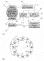
- Fig. 1 illustrates an example of a system 10, which comprises a combustor 12.
- the combustor 12 is illustrated as annular combustor, for example an annular gas turbine.
- the present invention is not limited to annular combustors and can be applied to any combustor, wherein thermoacoustic modes have nondegenerate eigenvalues, such as can-annular combustors.
- a thermoacoustic mode with nondegenerate eigenvalues may be understood as multiple coexisting modes with similar eigenfrequencies. Because, if the eigenfrequencies are close together, the modes may be coupled and may be hard to separate spectrally. As a result, they may be observed and considered as one thermoacoustic mode.
- the system 10 further comprises at least one sensor device 14 arranged and adapted to measure acoustic quantities in the combustor 12.
- the combustor may comprise at least one combustion chamber and a combustor plenum. Acoustic fields in any component of the combustor may be described by the term acoustic field of the combustor.
- the acoustic quantities can either be measured directly for example with a pressure transducer, or derived from a sensor measuring another quantity (e.g. heat release fluctuations of the flame or mechanical oscillations of combustor components), such as photomultiplier tubes for chemiluminescence or such as an accelerometer.
- thermoacoustics and flame dynamics are inherently coupled in thermoacoustic modes.
- the acoustics causes heat release fluctuations of the flame and vice versa. Therefore, the heat release rate can be considered as an indirect representation or indication of the acoustics.
- measurements representing heat release rate fluctuations are used instead of acoustic signals.
- the heat release rate can for example be quantified with help of the chemiluminescence from the combustion process, measured for instance with a Photomultiplier Tube (PMT) and optionally an optical bandpass filter.
- PMT Photomultiplier Tube
- a sensor for measuring a quantity indicative of an acoustic field of the combustor may be placed in, adjacent to or near any component of the combustor.
- the at least one sensor device 14 is adapted to output sensor signals s 1; s 2 ... s K , indicative of respective measurements of the acoustic field, e.g. with K sensors.
- Sensor signals from the at least one sensor device 14 may be provided to an (optional) analog-digital converter device 16, in the case the at least one sensor device 14 provides analog signals, while digital signals are needed for processing steps and devices, respectively, described in the following.
- the analog-digital converter device 16 is not necessary in the case analog signals from the at least one sensor device 14 can be processed by said processing steps and devices, respectively, described in the following. Nor is the analog-digital converter device 16 necessary in case the at least one sensor device 14 provides digital output signals.
- Each one of the at least one sensor device may be adapted to output one or more of the sensor signals.
- the sensor signals s 1 , s 2 ... s K are processed by a mode analyzer 20 as described further below.
- the mode analyzer device 20 estimates and outputs modal characteristics.
- the estimated modal characteristics include information indicating identified decay rate ⁇ , modal eigenvector V and/or process noise R of at least one eigenmode per monitored spectral peak in the acoustic field of the combustor 12.
- the modal eigenvectors can have any basis of spatial harmonic functions with order m around the circumference of the combustion chamber and/or combustor plenum.
- the eigenvectors can describe for instance standing waves, traveling waves or combinations thereof.
- the at least one decay rate estimate ⁇ can be used as a precursor for thermoacoustic stability directly.
- the mode analyzer device 20 analyzes modal amplitudes A j of at least one spectral peak in the acoustic field of the combustor 12, generated by the mode decomposer device 18 described further below.
- the sensor signals s 1 , s 2 ... s K are processed by a mode decomposer device 18, which projects the signals onto a modal vector basis ( V j ).
- the said vector basis can be set manually or set as the eigenvector estimate, identified by the mode analyzer device 20. If the vector basis is set manually, it typically corresponds to traveling or standing wave solutions of the acoustic field with spatial mode order m around the circumference of the combustor 12.
- the mode decomposer device 18 outputs modal amplitudes A j of at least one spectral peak in the acoustic field corresponding to mode order m of the combustor 12.
- the output of the wave decomposer device 18 may indicate acoustic clockwise ( F ) and anticlockwise ( G ) waves, which may be provided to a stability margin determination device 22.
- the outputs A j of the mode decomposer device 18 may be provided to a stability margin determination device 22, which determines or, at least, estimates at least one stability margin D j for the combustor 12.
- the stability margin determination device 22 uses the outputs A j of the mode decomposer device 18 as basis.
- the process noise R identified by the mode analyzer device 20 is used, along with the modal amplitudes A j , to determine a stability margin output.
- a determined/estimated stability margin is used to control the combustion process.
- information on the determined/estimated stability margin is provided to a controller 24.
- the controller 24 can be a technical controller for automatically controlling the combustor, for example, by using a pre-programmed algorithm, can be a human controller or operator.
- the combustor can be controlled by means of an actuator 26, which changes the combustion process parameters, such as, but not limited to, fuel split, staging strength or fuel flow to the pilot burner.
- a system according to the invention comprises a mode analyzer device and/or a mode decomposer device, which - as illustration - may operate according to the following considerations.
- an azimuthal mode order m comprises two eigenvalues with corresponding eigenvectors. In some cases, these eigenvalues are equal and the eigenvectors are orthogonal, leading to so-called degenerate eigenvalues. In practical systems, however, two distinct solutions may be possible because of side effects, including an azimuthal bulk velocity through the combustion chamber and azimuthally varying flame response characteristics (angular variation of the flame response).
- an azimuthal bulk velocity in the combustion chamber causes, at least promotes independent acoustic clockwise (F) and anticlockwise (G) waves with (slightly) different frequency and decay rate.
- azimuthally varying flame response characteristics can cause standing wave solutions, with frequency and decay rate depending on the angular orientation of the standing wave.
- combustors show both phenomena, yielding mixed modes, i.e. combinations of standing and traveling wave behavior.
- the azimuthal eigenmodes can be fully described by two complex amplitudes. Their amplitudes control the contribution of two independent harmonic basis functions around the circumference with mode order m .
- the two eigenmodes at mode order m may be resolved and considered individually.
- Mode decomposition may be based on an eigenvector basis that describes the acoustic field of the considered mode order m .
- Two main strategies are proposed: (a) Assuming at least one prescribed or pre-defined modal vector, such as a standard and/or known vector; (b) Obtaining an estimate of the eigenvectors by (online) identification of the system.
- one of strategies (a) and (b) may be carried out.
- both strategies (a) and (b) can be combined.
- Strategy (a) predominantly follows the outer loop of the block diagram in Fig. 1 , i.e. along the sequence of reference numbers 16-18-22-24.
- An example of the variant (a) is to decompose the signals in pure traveling waves.
- the signal can be decomposed in a clockwise traveling wave F ⁇ and anticlockwise wave ⁇ using the following steps.
- s ⁇ 1 s ⁇ 2 ... s ⁇ K C F ⁇ G ⁇
- the Moore-Penrose pseudoinverse can be used, yielding the decomposition in a least square sense.
- the above decomposition is performed in Fourier domain.
- FFT Fast Fourier Transforms
- the decomposed waves are obtained in frequency domain directly where the modal peaks can be analyzed visually and separated from other modes by means of a bandpass filter.
- bandpass filter As compared with the time domain, in the frequency domain more information per sensor is readily obtained, since the data comes with both amplitude and phase information.
- the combustion noise R can be fixed to a reasonable number, or estimated online from measured data when performing output-only modal identification by a mode analyzer device.
- the expected value for the precursor definition in equation [4] is monotonically increasing with the decay rates of the corresponding traveling waves. For marginal stability, the precursor value will go to zero.
- Evolution of precursors based on modal amplitudes can be monitored for different modal vectors individually, preferably normalized by the estimate of noise level R , exciting the system around the frequency of the considered mode.
- Preferred implementations of the mode decomposer and stability margin determination device were explained here with traveling waves as basis vector of the system, but the methods apply under any change of basis, including all standing and mixed wave bases.
- Strategy (b) predominantly follows the smaller clockwise loop in Fig. 1 , i.e. along the sequence of reference numbers 16-20-24.
- An example of variant (b) may involve system identification on basis of the sensor signals.
- the method for identifying the thermoacoustic system disclosed herein may be practiced for a variety of purposes, including but not limited to determining a stability margin. Further applications include the determination of mode shapes and eigenfrequencies or passive control strategies to obtain a more stable system.
- the used model structure for system identification is a state space representation, with acoustic variables in state vector x , for example traveling waves F ⁇ and ⁇ :
- Output-only modal identification methods can estimate matrix A and the stochastic forcing vector w.
- the state-space model in total can be identified by the Stochastic Subspace Identification algorithm (SSI).
- the eigenvalues ⁇ and eigenvectors V are retrieved by solving the eigenvalue problem of system matrix A , wherein w is representative for the noise strength exciting the system.
- the eigenvalues contain both the decay rate and the eigenfrequency of the eigenmodes.
- A can be determined by ordinary least squares, with residual w .
- FDD Fourier Domain Decomposition
- fitting strategies can be applied to estimate the eigenvectors only.
- Mode decomposition onto these eigenvectors can then be applied to obtain the dynamic amplitudes of the eigenmodes.
- These modal amplitudes can be used to find a precursor following strategy (a), or they can be fed back to the modal analyzer to find the remaining modal characteristics.
- the decay rate can be found by fitting the autocorrelation function envelope of the modal amplitude A .
- the standard deviation of (a long) combustion noise forcing vector w gives the estimate of noise strength R .
- the estimate of R can be used in the stability margin determination device as described in strategy (a).
- the decay rate When the decay rate is estimated, it can serve as a quantitative stability margin. This strategy will be most suited for slowly changing system parameters, because the identification process requires large data sets. Precursors based on modal amplitude (strategy (a)) can be monitored as quantitative measure to represent short term stability changes with the estimated decay rate as reference.
- identification can provide more information about the system parameters which can prove to be helpful in taking the right control action to manage the stability margin of the system. For example, the orientation of a standing wave can suggest at what burners fuel staging should be applied to gain stability margin. Moreover, subcritical and supercritical bifurcation points could be predicted with help of the estimated eigenfrequencies, when sufficient information about the flame response is known. This may be a reason, for example, to retain a larger or smaller stability margin for a specific mode.
- Fig. 3 shows exemplary spectra of clockwise and anticlockwise waves of a split, i.e. non-degenerate, mode.
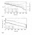
- Fig. 4 shows the precursors based on traveling wave and standing wave amplitudes, applied to simulated data of a (annular) thermoacoustic system in a (annular) combustion chamber, using Equation [4] according to strategy (a) (comparable results are obtained in the case of any thermoacoustic system in a combustion chamber in general).
- the damping in the model was decreased linearly such that the least stable mode crosses zero after 297 seconds. Other parameters were fixed in such way that the least stable mode lies in the mixed zone with
- 2.6.
- An exponential moving average (EMA) with exponent of 0.25 s -1 is applied to smooth the results.
- the precursors go down towards zero as the damping decreases. From about 280 seconds the values drop down quickly and go to zero asymptotically with the exponent of the EMA-filter.
- the value for D f is clearly lower than D g , which could be expected by the amplitude ratio of 2.6.
- One of the standing wave precursors practically shows the same stability margin, from which it can be deduced that the system is in the mixed region.
- An overbar denotes that the quantity is estimated on basis of a finite time window.
- Fig. 5 shows the precursors (identified eigenmodes) applied to simulated data of a (e.g. annular) thermoacoustic system in a (e.g. annular) combustion chamber, using identified eigenvectors and compared to the variant of analysis based on traveling waves. Note that this is a combination of strategy (a) and (b). Again Equation [4] defines the precursor, but the modal bases are taken as the identified eigenvectors. An overbar denotes that the quantity is estimated on basis of a finite time window.
- the second mode is also affected by the imperfect identification of the eigenvectors.
- An instantaneous value for the amplitude gives very poor information about the stability; it is rather the expected value (i.e. long-time average) that can give a reliable quantification of the state of the system.
- a trade-off has to be made between the averaging time and the ability to observe temporal development of the system itself. Performing identification over a longer period of stable operation can yield an estimate of the decay rate (strategy (b)), to which amplitude based precursors can be related.
- the decomposition using a pre-defined basis of traveling waves and using a basis of the identified eigenvectors yield approximately the same precursor result for the least stable mode which is the mode of interest.
- a precursor based on a properly identified vector basis will yield the best results. If this is not available, the lowest precursor of standing wave and traveling wave decomposition may be taken as the stability margin for the system.
- Fig. 6 shows the estimated decay rate as the stability margin following strategy (b).
- the estimated values for the decay rates are very close to the theoretical values ⁇ . Because the dynamic parameters of the thermoacoustic system change slowly, a proper estimate of the decay rate can be obtained. In this case, it is the preferred precursor, since the quantity has a physical meaning.
Landscapes
- Engineering & Computer Science (AREA)
- Chemical & Material Sciences (AREA)
- Combustion & Propulsion (AREA)
- Mechanical Engineering (AREA)
- General Engineering & Computer Science (AREA)
- Investigating Or Analyzing Materials By The Use Of Ultrasonic Waves (AREA)
- Testing Of Engines (AREA)
Description
- The present invention relates to a method and an apparatus for monitoring a combustor (e.g. a gas turbine) and, particularly, for monitoring the dynamic stability margin of combustor (e.g. a gas turbine).
- Several methods to determine a stability margin of a combustor or combustion chamber have been proposed. Approaches to determine a stability margin are usually developed and/or validated on laboratory combustors. The degree of effectivity in applying the same strategies to full scale industrial combustors and, particularly, annular gas turbines is questionable. For example, the measurement location may corrupt the stability margin estimation.
- Document
US 2008/072605 A1 describes a method for controlling a temperature distribution within a combustor having a plurality of chamber sections comprising controlling a fuel-to-air ratio in the chamber sections. At least two chamber sections have different fuel-to-air ratios to create a nonuniform temperature distribution within the combustor to reduce thermoacoustic instabilities. When there is a uniform temperature distribution, the system reaches its highest level of noise and instability. -
US 5 719 791 A describes active control of detrimental instabilities in practical combustors. A signal of a sensor is measured from which modal functions (amplitude, phase) and frequency of excited combustor modes are determined. Based on the modal functions and frequencies, the controller determines gain and phase shift for each mode or uses a predetermined gain and phase shift and combines the modes to generate a time-varying control signal. Based on the control signal, the actuator produces a secondary system of oscillations within the combustor that tends to damp the instability or excites oscillations. - Document
US 2005/0247064 A1 discloses systems and methods for determining a stability margin of a combustor. One embodiment includes the steps of providing a measuring device in communication with the combustor, wherein the measuring device generates signals indicative of combustor quantities; performing an autocorrelation calculation on the signals to determine the correlation time of the signals in the combustor and determining the damping coefficient from the autocorrelation calculation, wherein the damping coefficient signifies a proximity of the combustor to instability. The damping coefficient may be estimated form the oscillatory envelope of the autocorrelation calculation data. - Document
EP 1 286 031 A1 relates to a gas turbine apparatus in which a frequency analyzing section analyzes the frequency of at least one pressure oscillation in combustors of a gas turbine and the acceleration oscillation of each of the combustors and outputs a frequency analysis result as the result of frequency analysis for a plurality of predetermined frequency bands. The combustion oscillations can be suppressed by a control unit that controls the fuel flow rate and the air flow rate, based on the results. - It is an object of the present invention to provide solutions for a reliable determination of a stability margin of a combustor and, for example, an annular gas turbine combustors or a full gas turbine combustor.
- To solve the above object, the present invention provides subject-matter according to the independent claims. Preferred embodiments of the present invention are defined in dependent claims.
- A method of determining a stability margin for a combustor by assessing modal dynamics of the thermoacoustic system is disclosed. Assessment of modal dynamics of the thermoacoustic system is understood to relate to the characterization of the thermoacoustic vibration (modes) originating from the excitation by the combustion process. The thermoacoustic phenomenon may also be referred to as combustion dynamics or combustion instability.
- In general, modal characteristics of at least one spectral peak in an acoustic field of the combustor are obtained and at least one stability margin is determined based on the obtained modal characteristics. In some embodiments, the modal characteristics of the at least one spectral peak in the acoustic field of the combustor may comprise modal contributions. In particular, modal contributions to the at least one spectral peak of the acoustic field may be determined by obtaining a basis of modal vectors (e.g. comprising harmonic functions) and by mode decomposition of measured acoustic amplitudes onto the obtained basis.
- Furthermore, a computer program product, an apparatus and a system for determining a stability margin are disclosed.
- In the following, possible embodiments are defined:
The method comprises obtaining modal characteristics of at least one spectral peak in an acoustic field of the combustor, determining at least one stability margin for the combustor based on the obtained modal characteristics of the at least one spectral peak in the acoustic field of the combustor. - In the method, the step of obtaining the modal characteristics may comprise identifying the thermoacoustic system, based on a state space model structure with stochastic input, to estimate
- -- eigenvectors and/or
- -- decay rates of eigenmodes and/or
- -- eigenfrequencies and/or
- -- stochastic forcing amplitude.
- In the method, the step of obtaining the modal characteristics may comprise assuming at least one pre-defined modal vector, in particular at least one pre-defined modal vector corresponding to a standing acoustic wave or a traveling acoustic wave, mode decomposition based on the at least one pre-defined modal vector to obtain modal amplitudes, and estimating a decay rate and/or frequency of at least one of the modal amplitudes.
- In the method, the at least one stability margin for the combustor may be determined as the estimated decay rate.
- The method may comprise that the thermodynamic system is decomposed onto at least one estimated eigenvector and the at least one stability margin for the combustor is determined based on the modal amplitude on basis of an estimated eigenvector.
- The method may comprise that the thermodynamic system is decomposed onto at least one assumed, pre-defined modal vector, and the at least one stability margin for the combustor is determined based on the modal amplitude on basis of an assumed, pre-defined modal vector.
- In the method, the combustor may be an annular combustor, wherein the modal characteristics may be defined on basis of an azimuthal coordinate and an azimuthal mode order m, and/or the at least one modal vector is based on the azimuthal mode number m.
- In the method, the at least one spectral peak is determined based on acoustic signals in the combustor which may be measured or deduced in the combustor.
- Computer program product including program code configured to, when executed in a computing device, carry out the steps of one of the preceding claims.
- The apparatus comprises at least one of:
- -- a mode analyzer device being adapted to obtain modal characteristics of at least one spectral peak in an acoustic field of the combustor and
- -- a mode decomposer device being adapted to decompose the thermoacoustic system onto a modal vector,
- The apparatus may further comprise at least two acoustic sensors to measure or deduce acoustic signals in the combustor.
- In the apparatus, the mode analyzer device is adapted to determine the stability margin for the combustor based on a decay rate of the at least one acoustic mode, or the stability margin determination device may be adapted to determine the stability margin for the combustor based on an amplitude of the modal characteristics, and/or an acoustic noise in the combustor.
- In the apparatus, the mode analyzer device or the mode decomposed device may be adapted to determine the acoustic noise in the combustor on the basis of acoustic signals measured or deduced in the combustor.
- In the apparatus, the combustor may be an annular combustor, wherein the mode decomposer device may be adapted to decompose the acoustic field onto a modal vector, based on an azimuthal mode order m, and/or the mode analyzer device may be adapted to determine the modal characteristics on basis of an azimuthal mode order m.
- The system may comprise an apparatus according to one of the above embodiments and a combustor.
- The system comprises the controller being adapted to control the operation of the combustor based on the stability margin for the combustor, determined by the stability margin determination device of the apparatus or the mode analyzer device.
- In the system, the combustor may be the combustor of an annular gas turbine.
- In the system, the combustor may be a gas turbine combustor.
- In the system, the modal characteristics may be obtained on basis of fluctuating heat release rate of the combustor.
- In the system, at least one stability margin is determined based on the obtained modal characteristics of the at least one spectral peak in the fluctuating heat release rate of the combustor.
- In the following, the present invention is described with reference to the attached drawings, which show:
- Fig. 1
- a schematic illustration of a system according to the present invention including an apparatus according to the present invention,
- Fig. 2
- a schematic illustration of the annular geometry of a combustor (e.g. annular gas turbine),
- Fig. 3
- exemplary spectra of a split mode, yielding nondegenerate (split) eigenmodes
- Fig. 4
- exemplary graphical representation of standard precursors,
- Fig. 5
- exemplary graphical representations of tailored precursors.
- Fig. 6
- exemplary graphical representation of identified decay rates as precursors
-
Fig. 1 illustrates an example of asystem 10, which comprises acombustor 12. InFig. 2 , thecombustor 12 is illustrated as annular combustor, for example an annular gas turbine. However, the present invention is not limited to annular combustors and can be applied to any combustor, wherein thermoacoustic modes have nondegenerate eigenvalues, such as can-annular combustors. A thermoacoustic mode with nondegenerate eigenvalues may be understood as multiple coexisting modes with similar eigenfrequencies. Because, if the eigenfrequencies are close together, the modes may be coupled and may be hard to separate spectrally. As a result, they may be observed and considered as one thermoacoustic mode. - Returning to
Fig. 1 , thesystem 10 further comprises at least onesensor device 14 arranged and adapted to measure acoustic quantities in thecombustor 12. The combustor may comprise at least one combustion chamber and a combustor plenum. Acoustic fields in any component of the combustor may be described by the term acoustic field of the combustor. The acoustic quantities can either be measured directly for example with a pressure transducer, or derived from a sensor measuring another quantity (e.g. heat release fluctuations of the flame or mechanical oscillations of combustor components), such as photomultiplier tubes for chemiluminescence or such as an accelerometer. - As known to the skilled person, acoustics and flame dynamics are inherently coupled in thermoacoustic modes. The acoustics causes heat release fluctuations of the flame and vice versa. Therefore, the heat release rate can be considered as an indirect representation or indication of the acoustics. In some embodiments, measurements representing heat release rate fluctuations are used instead of acoustic signals. The heat release rate can for example be quantified with help of the chemiluminescence from the combustion process, measured for instance with a Photomultiplier Tube (PMT) and optionally an optical bandpass filter.
- Accordingly, as will be apparent to the skilled person, a sensor for measuring a quantity indicative of an acoustic field of the combustor may be placed in, adjacent to or near any component of the combustor.
- The at least one
sensor device 14 is adapted to output sensor signals s 1; s 2 ... sK , indicative of respective measurements of the acoustic field, e.g. with K sensors. Sensor signals from the at least onesensor device 14 may be provided to an (optional) analog-digital converter device 16, in the case the at least onesensor device 14 provides analog signals, while digital signals are needed for processing steps and devices, respectively, described in the following. The analog-digital converter device 16 is not necessary in the case analog signals from the at least onesensor device 14 can be processed by said processing steps and devices, respectively, described in the following. Nor is the analog-digital converter device 16 necessary in case the at least onesensor device 14 provides digital output signals. Each one of the at least one sensor device may be adapted to output one or more of the sensor signals. - The sensor signals s 1, s 2 ... sK are processed by a
mode analyzer 20 as described further below. - The
mode analyzer device 20 estimates and outputs modal characteristics. The estimated modal characteristics include information indicating identified decay rate α, modal eigenvector V and/or process noise R of at least one eigenmode per monitored spectral peak in the acoustic field of thecombustor 12. The modal eigenvectors can have any basis of spatial harmonic functions with order m around the circumference of the combustion chamber and/or combustor plenum. The eigenvectors can describe for instance standing waves, traveling waves or combinations thereof. The at least one decay rate estimate α can be used as a precursor for thermoacoustic stability directly. - In some embodiments, the
mode analyzer device 20 analyzes modal amplitudes Aj of at least one spectral peak in the acoustic field of thecombustor 12, generated by themode decomposer device 18 described further below. - In some embodiments, the sensor signals s 1, s 2 ... sK are processed by a
mode decomposer device 18, which projects the signals onto a modal vector basis (Vj ). The said vector basis can be set manually or set as the eigenvector estimate, identified by themode analyzer device 20. If the vector basis is set manually, it typically corresponds to traveling or standing wave solutions of the acoustic field with spatial mode order m around the circumference of thecombustor 12. Themode decomposer device 18 outputs modal amplitudes Aj of at least one spectral peak in the acoustic field corresponding to mode order m of thecombustor 12. For example, the output of thewave decomposer device 18 may indicate acoustic clockwise (F) and anticlockwise (G) waves, which may be provided to a stabilitymargin determination device 22. The outputs Aj of themode decomposer device 18 may be provided to a stabilitymargin determination device 22, which determines or, at least, estimates at least one stability margin Dj for thecombustor 12. To this end, the stabilitymargin determination device 22 uses the outputs Aj of themode decomposer device 18 as basis. In some embodiments, the process noise R identified by themode analyzer device 20 is used, along with the modal amplitudes Aj , to determine a stability margin output. - A determined/estimated stability margin is used to control the combustion process. To this end, information on the determined/estimated stability margin is provided to a
controller 24. Thecontroller 24 can be a technical controller for automatically controlling the combustor, for example, by using a pre-programmed algorithm, can be a human controller or operator. The combustor can be controlled by means of anactuator 26, which changes the combustion process parameters, such as, but not limited to, fuel split, staging strength or fuel flow to the pilot burner. - In general, a system according to the invention comprises a mode analyzer device and/or a mode decomposer device, which - as illustration - may operate according to the following considerations.
- Modeling azimuthal modes in annular geometries, an azimuthal mode order m comprises two eigenvalues with corresponding eigenvectors. In some cases, these eigenvalues are equal and the eigenvectors are orthogonal, leading to so-called degenerate eigenvalues. In practical systems, however, two distinct solutions may be possible because of side effects, including an azimuthal bulk velocity through the combustion chamber and azimuthally varying flame response characteristics (angular variation of the flame response).
- On the one hand, an azimuthal bulk velocity in the combustion chamber (or combustor annulus) causes, at least promotes independent acoustic clockwise (F) and anticlockwise (G) waves with (slightly) different frequency and decay rate.
- On the other hand, azimuthally varying flame response characteristics can cause standing wave solutions, with frequency and decay rate depending on the angular orientation of the standing wave.
- In general, combustors show both phenomena, yielding mixed modes, i.e. combinations of standing and traveling wave behavior.
- The azimuthal eigenmodes can be fully described by two complex amplitudes. Their amplitudes control the contribution of two independent harmonic basis functions around the circumference with mode order m.
- In order to predict the moment where the lowest decay rate will cross zero resulting in exponential growth, monitoring a mix of the two eigenmodes will yield a bias towards stable operation. For a more accurate or more reliable stability margin determination, the two eigenmodes at mode order m may be resolved and considered individually.
- To this end, a mode decomposition of measured acoustic signals may be carried out. Mode decomposition may be based on an eigenvector basis that describes the acoustic field of the considered mode order m. Two main strategies are proposed: (a) Assuming at least one prescribed or pre-defined modal vector, such as a standard and/or known vector; (b) Obtaining an estimate of the eigenvectors by (online) identification of the system. In some embodiments, one of strategies (a) and (b) may be carried out. Alternatively, in some embodiments, both strategies (a) and (b) can be combined.
- Strategy (a) predominantly follows the outer loop of the block diagram in
Fig. 1 , i.e. along the sequence of reference numbers 16-18-22-24. An example of the variant (a) is to decompose the signals in pure traveling waves. The signal can be decomposed in a clockwise traveling wave F̂ and anticlockwise wave Ĝ using the following steps. Construct a matrix C stating what the sensor outputs should be for given traveling wave amplitudes.
- The hats denote that the variables might be analytic, i.e. complex variables. For two sensor channels, the decomposed traveling waves can now be found using the inverse of C

- For more than two sensors, the Moore-Penrose pseudoinverse can be used, yielding the decomposition in a least square sense.
- Preferably, the above decomposition is performed in Fourier domain. Fast Fourier Transforms (FFT) are often already implemented and optimized in monitoring hardware and/or software of a combustion system. The decomposed waves are obtained in frequency domain directly where the modal peaks can be analyzed visually and separated from other modes by means of a bandpass filter. As compared with the time domain, in the frequency domain more information per sensor is readily obtained, since the data comes with both amplitude and phase information.
- An example for the precursors based on the average modal amplitudes is given in equation [3], determined from a sample with N time steps.

- When the strength of the combustion noise R, exciting the acoustic field, is known or estimated, it can be used in defining the following precursors:

- The combustion noise R can be fixed to a reasonable number, or estimated online from measured data when performing output-only modal identification by a mode analyzer device. The expected value for the precursor definition in equation [4] is monotonically increasing with the decay rates of the corresponding traveling waves. For marginal stability, the precursor value will go to zero.
- Evolution of precursors based on modal amplitudes can be monitored for different modal vectors individually, preferably normalized by the estimate of noise level R, exciting the system around the frequency of the considered mode. Preferred implementations of the mode decomposer and stability margin determination device were explained here with traveling waves as basis vector of the system, but the methods apply under any change of basis, including all standing and mixed wave bases.
- Strategy (b) predominantly follows the smaller clockwise loop in
Fig. 1 , i.e. along the sequence of reference numbers 16-20-24. An example of variant (b) may involve system identification on basis of the sensor signals. In general, the method for identifying the thermoacoustic system disclosed herein may be practiced for a variety of purposes, including but not limited to determining a stability margin. Further applications include the determination of mode shapes and eigenfrequencies or passive control strategies to obtain a more stable system. - The used model structure for system identification is a state space representation, with acoustic variables in state vector x, for example traveling waves F̂ and Ĝ:

- The subscript n denotes discrete steps in time. Output-only modal identification methods can estimate matrix A and the stochastic forcing vector w. The state-space model in total can be identified by the Stochastic Subspace Identification algorithm (SSI). The eigenvalues λ and eigenvectors V are retrieved by solving the eigenvalue problem of system matrix A, wherein w is representative for the noise strength exciting the system. The eigenvalues contain both the decay rate and the eigenfrequency of the eigenmodes. When the sensor noise can be neglected, A can be determined by ordinary least squares, with residual w.
- Alternatively or additionally, Fourier Domain Decomposition (FDD) and fitting strategies can be applied to estimate the eigenvectors only. Mode decomposition onto these eigenvectors can then be applied to obtain the dynamic amplitudes of the eigenmodes. These modal amplitudes can be used to find a precursor following strategy (a), or they can be fed back to the modal analyzer to find the remaining modal characteristics.
- To find the eigenvalues from a modal amplitude A, the following model is used for all amplitudes independently

- Alternatively, the decay rate can be found by fitting the autocorrelation function envelope of the modal amplitude A.
- The standard deviation of (a long) combustion noise forcing vector w gives the estimate of noise strength R. The estimate of R can be used in the stability margin determination device as described in strategy (a).
- When the decay rate is estimated, it can serve as a quantitative stability margin. This strategy will be most suited for slowly changing system parameters, because the identification process requires large data sets. Precursors based on modal amplitude (strategy (a)) can be monitored as quantitative measure to represent short term stability changes with the estimated decay rate as reference.
- Furthermore, identification can provide more information about the system parameters which can prove to be helpful in taking the right control action to manage the stability margin of the system. For example, the orientation of a standing wave can suggest at what burners fuel staging should be applied to gain stability margin. Moreover, subcritical and supercritical bifurcation points could be predicted with help of the estimated eigenfrequencies, when sufficient information about the flame response is known. This may be a reason, for example, to retain a larger or smaller stability margin for a specific mode.
-
Fig. 3 shows exemplary spectra of clockwise and anticlockwise waves of a split, i.e. non-degenerate, mode. -
Fig. 4 shows the precursors based on traveling wave and standing wave amplitudes, applied to simulated data of a (annular) thermoacoustic system in a (annular) combustion chamber, using Equation [4] according to strategy (a) (comparable results are obtained in the case of any thermoacoustic system in a combustion chamber in general). The damping in the model was decreased linearly such that the least stable mode crosses zero after 297 seconds. Other parameters were fixed in such way that the least stable mode lies in the mixed zone with |F̂/Ĝ| = 2.6. - An exponential moving average (EMA) with exponent of 0.25s -1 is applied to smooth the results. The precursors go down towards zero as the damping decreases. From about 280 seconds the values drop down quickly and go to zero asymptotically with the exponent of the EMA-filter. The value for
D f is clearly lower thanD g, which could be expected by the amplitude ratio of 2.6. One of the standing wave precursors practically shows the same stability margin, from which it can be deduced that the system is in the mixed region. An overbar denotes that the quantity is estimated on basis of a finite time window. - In some embodiments, it may be preferable to obtain modal characteristics by identifying the thermoacoustic system based on a state space model structure with stochastic input.
Fig. 5 shows the precursors (identified eigenmodes) applied to simulated data of a (e.g. annular) thermoacoustic system in a (e.g. annular) combustion chamber, using identified eigenvectors and compared to the variant of analysis based on traveling waves. Note that this is a combination of strategy (a) and (b). Again Equation [4] defines the precursor, but the modal bases are taken as the identified eigenvectors. An overbar denotes that the quantity is estimated on basis of a finite time window. System identification of the eigenvectors is applied on the first half of the time series. Using these vectors, the precursors (D v1,D v2) inFig. 5 are generated. Compared to the traveling wave solutions (D f, Dg ), the difference between the two modes (v1, v2) becomes more pronounced, mainly increasing the stability margin estimate for the more stable eigenmode. For the same damping, both eigenmodes result in the same value for the precursor, compareD vi . ≈ 1.6 , for αi = - 10s -1. This suggests that the decomposition on basis of the identified eigenvectors was successful in making the stability margin determination more accurate in the present embodiment. Only after a certain period of exponential growth of the least stable mode, the second mode is also affected by the imperfect identification of the eigenvectors. An instantaneous value for the amplitude gives very poor information about the stability; it is rather the expected value (i.e. long-time average) that can give a reliable quantification of the state of the system. A trade-off has to be made between the averaging time and the ability to observe temporal development of the system itself. Performing identification over a longer period of stable operation can yield an estimate of the decay rate (strategy (b)), to which amplitude based precursors can be related. - In this particular example, the decomposition using a pre-defined basis of traveling waves and using a basis of the identified eigenvectors yield approximately the same precursor result for the least stable mode which is the mode of interest. However, depending on the system, this does not have to be the case. A precursor based on a properly identified vector basis will yield the best results. If this is not available, the lowest precursor of standing wave and traveling wave decomposition may be taken as the stability margin for the system.
-
Fig. 6 shows the estimated decay rate as the stability margin following strategy (b). The estimated values for the decay rates are very close to the theoretical values α. Because the dynamic parameters of the thermoacoustic system change slowly, a proper estimate of the decay rate can be obtained. In this case, it is the preferred precursor, since the quantity has a physical meaning.
Claims (19)
- Method of controlling the operation of a combustor, comprising determining a stability margin for the combustor (12) by assessing modal dynamics of a thermoacoustic system, the stability margin to predict an exponential growth of an amplitude of at least one eigenmode in the combustor, characterized in- measuring sensor signals indicative of measurements of an acoustic field in the combustor,- obtaining modal characteristics of at least one eigenmode of a spectral peak of the acoustic field in the combustor (12), wherein the at least one eigenmode of the spectral peak is determined based on acoustic signals in the combustor (12),- determining at least one stability margin for the combustor (12) based on the obtained modal characteristics of the at least one eigenmode of the spectral peak in the acoustic field in the combustor,- controlling the operation of the combustor by means of an actuator (26) which changes
combustion process parameters based on the determined stability margin. - Method according to the preceding claim, wherein obtaining the modal characteristics comprises:- identifying the thermoacoustic system, based on a state space representation with stochastic input, to estimate-- eigenvectors and/or-- decay rates of eigenmodes and/or-- eigenfrequencies and/or-- process noise.
- Method according to claim 1, wherein obtaining the modal characteristics comprises:- assuming at least one pre-defined modal vector- mode decomposition based on the at least one pre-defined modal vector to obtain modal amplitudes, and- estimating a decay rate and/or frequency of at least one of the modal amplitudes.
- Method according to claim 2 or 3, wherein the at least one stability margin for the combustor (12) is determined as the estimated decay rate.
- Method according to claim 2, wherein:- the thermoacoustic system is decomposed onto at least one estimated eigenvector, and- the at least one stability margin for the combustor (12) is determined based on the modal amplitude on basis of an estimated eigenvector.
- Method according to claim 3, wherein:- the thermoacoustic system is decomposed onto at least one assumed, pre-defined modal vector, and- the at least one stability margin for the combustor (12) is determined based on the modal amplitude on basis of an assumed, pre-defined modal vector.
- Method according to one of the preceding claims, wherein- the modal characteristics are defined on basis of an azimuthal coordinate and an azimuthal mode order m, and/or- the at least one modal vector is based on the azimuthal mode number m.
- Method according to one of the preceding claims, wherein the at least one spectral peak is determined based on acoustic signals measured directly or deduced from another measurement.
- Method according to one of the preceding claims, wherein the at least one spectral peak is determined based on a fluctuating heat release rate of the combustor (12).
- Computer program product including program code configured to, when executed in a computing device, carry out the steps of one of the preceding claims.
- Apparatus for controlling the operation of a combustor by determining a stability margin for the combustor (12) by assessing modal dynamics of a thermoacoustic system, the stability margin to predict an exponential growth of an amplitude of at least one eigenmode in the combustor, comprising- at least one sensor device (14) to measure or deduce acoustic signals in the combustor, characterized in that the apparatus comprises:- at least one of:-- (i) a mode analyzer device (20) being adapted to obtain modal characteristics of at least one eigenmode of a spectral peak of an acoustic field in the combustor (12) and to determine a stability margin for the combustor;-- (ii) a mode decomposer device (18) being adapted to decompose the thermoacoustic system onto a modal vector, and- a stability margin determination device (22) being adapted to determine at least one stability margin for the combustor (12) based on at least one of the obtained modal characteristics of the at least one eigenmode and the modal vector decomposition, and- a controller to control the operation of the combustor by means of an actuator (26) which changes the combustion process parameters based on the stability margin determined by the stability margin determination device (22) or the mode analyzer device (20).
- Apparatus according to the preceding claim, said sensor device (14) further comprising at least two sensors to measure or represent acoustic signals in the combustor (12).
- Apparatus according to claim 11 or 12, wherein:- the mode analyzer device (20) is adapted to determine the stability margin for the combustor (12) based on a decay rate of the at least one acoustic mode, and/or- the stability margin determination device (22) is adapted to determine the stability margin for the combustor (12) based on-- an amplitude of the modal characteristics, and/or-- an acoustic noise in the combustor (12).
- Apparatus according to the preceding claim, wherein the mode analyzer device (20) or the mode decomposed device (18) is adapted to determine the acoustic noise in the combustor (12) on the basis of acoustic signals measured directly or deduced from another measurement.
- Apparatus according to one of the claims 11 to 14, wherein- the mode decomposer device (18) is adapted to decompose the acoustic field onto a modal vector, based on an azimuthal mode order m, and/or- the mode analyzer device (20) is adapted to determine the modal characteristics on basis of an azimuthal mode order m.
- Apparatus according to one of claims 11 to 15, wherein the mode analyzer device (20) is adapted to determine the stability margin for the combustor (12) based on acoustic signals measured directly or deduced from another measurement.
- Apparatus according to one of claims 11 to 16, wherein the mode analyzer device (20) is adapted to determine the stability margin for the combustor (12) based on a fluctuating heat release rate of the combustor (12).
- System comprising- an apparatus according to one of the claims 11 to 17,- the combustor (12).
- System according to claim 18, wherein the combustor (12) is a gas turbine combustor.
Applications Claiming Priority (3)
| Application Number | Priority Date | Filing Date | Title |
|---|---|---|---|
| EP15001745 | 2015-06-12 | ||
| EP15003308.2A EP3104078A1 (en) | 2015-06-12 | 2015-11-20 | Thermoacoustic precursor method and apparatus |
| PCT/EP2016/000963 WO2016198164A1 (en) | 2015-06-12 | 2016-06-10 | Thermoacoustic precursor method and apparatus |
Publications (2)
| Publication Number | Publication Date |
|---|---|
| EP3308079A1 EP3308079A1 (en) | 2018-04-18 |
| EP3308079B1 true EP3308079B1 (en) | 2021-11-17 |
Family
ID=53487163
Family Applications (2)
| Application Number | Title | Priority Date | Filing Date |
|---|---|---|---|
| EP15003308.2A Withdrawn EP3104078A1 (en) | 2015-06-12 | 2015-11-20 | Thermoacoustic precursor method and apparatus |
| EP16732939.0A Active EP3308079B1 (en) | 2015-06-12 | 2016-06-10 | Thermoacoustic precursor method and apparatus |
Family Applications Before (1)
| Application Number | Title | Priority Date | Filing Date |
|---|---|---|---|
| EP15003308.2A Withdrawn EP3104078A1 (en) | 2015-06-12 | 2015-11-20 | Thermoacoustic precursor method and apparatus |
Country Status (4)
| Country | Link |
|---|---|
| US (1) | US10948185B2 (en) |
| EP (2) | EP3104078A1 (en) |
| CN (1) | CN107995943B (en) |
| WO (1) | WO2016198164A1 (en) |
Families Citing this family (3)
| Publication number | Priority date | Publication date | Assignee | Title |
|---|---|---|---|---|
| WO2020214470A1 (en) * | 2019-04-19 | 2020-10-22 | Purdue Research Foundation | Utilization of fast-response pressure measurements to nonintrusively monitor blade vibration in axial compressors |
| CN112326730A (en) * | 2020-10-21 | 2021-02-05 | 北京航空航天大学 | Experimental method and device for measuring heat release rate pulsation by adopting multiple microphones |
| CN113686580B (en) * | 2021-08-25 | 2024-05-10 | 西北工业大学 | Standing wave oscillation experimental device for simulating nonlinear acoustic vibration mode of engine combustion chamber |
Citations (2)
| Publication number | Priority date | Publication date | Assignee | Title |
|---|---|---|---|---|
| US5719791A (en) * | 1995-03-17 | 1998-02-17 | Georgia Tech Research Corporation | Methods, apparatus and systems for real time identification and control of modes of oscillation |
| US20080072605A1 (en) * | 2006-09-26 | 2008-03-27 | United Technologies Corporation | Method for control of thermoacoustic instabilities in a combustor |
Family Cites Families (23)
| Publication number | Priority date | Publication date | Assignee | Title |
|---|---|---|---|---|
| US5082421A (en) * | 1986-04-28 | 1992-01-21 | Rolls-Royce Plc | Active control of unsteady motion phenomena in turbomachinery |
| KR0130635B1 (en) * | 1992-10-14 | 1998-04-09 | 모리시타 요이찌 | Combustion apparatus |
| US5428951A (en) * | 1993-08-16 | 1995-07-04 | Wilson; Kenneth | Method and apparatus for active control of combustion devices |
| US5544478A (en) * | 1994-11-15 | 1996-08-13 | General Electric Company | Optical sensing of combustion dynamics |
| US5582515A (en) * | 1995-05-04 | 1996-12-10 | Foster Wheeler Energy Corporation | Acoustically pulsating burner with integral adjustable Sondhauss thermoacoustic elements |
| US5791889A (en) * | 1996-04-26 | 1998-08-11 | The United States Of America As Represented By The United States Department Of Energy | Combustor oscillating pressure stabilization and method |
| US6464489B1 (en) * | 1997-11-24 | 2002-10-15 | Alstom | Method and apparatus for controlling thermoacoustic vibrations in a combustion system |
| US6205765B1 (en) * | 1999-10-06 | 2001-03-27 | General Electric Co. | Apparatus and method for active control of oscillations in gas turbine combustors |
| US6522991B2 (en) * | 2001-05-04 | 2003-02-18 | United Technologies Corporation | Suppressing oscillations in processes such as gas turbine combustion |
| JP4056232B2 (en) * | 2001-08-23 | 2008-03-05 | 三菱重工業株式会社 | Gas turbine control device, gas turbine system, and gas turbine remote monitoring system |
| US6973791B2 (en) * | 2003-12-30 | 2005-12-13 | General Electric Company | Method and apparatus for reduction of combustor dynamic pressure during operation of gas turbine engines |
| US7194382B2 (en) * | 2004-02-06 | 2007-03-20 | Georgia Tech Research Corporation | Systems and methods for detection of combustor stability margin |
| EP1688671B2 (en) * | 2005-02-03 | 2019-01-09 | Ansaldo Energia IP UK Limited | Protection method and control system for a gas turbine |
| US7441411B2 (en) * | 2005-09-16 | 2008-10-28 | General Electric Company | Method and apparatus to detect onset of combustor hardware damage |
| US8001761B2 (en) * | 2006-05-23 | 2011-08-23 | General Electric Company | Method and apparatus for actively controlling fuel flow to a mixer assembly of a gas turbine engine combustor |
| US7970570B2 (en) * | 2006-10-13 | 2011-06-28 | General Electric Company | Methods and systems for analysis of combustion dynamics in the time domain |
| US7966801B2 (en) * | 2006-12-07 | 2011-06-28 | General Electric Company | Apparatus and method for gas turbine active combustion control system |
| US7908072B2 (en) * | 2007-06-26 | 2011-03-15 | General Electric Company | Systems and methods for using a combustion dynamics tuning algorithm with a multi-can combustor |
| EP2239505A1 (en) * | 2009-04-08 | 2010-10-13 | Siemens Aktiengesellschaft | Method for analysing the tendency to hum of a combustion chamber and method for controlling a gas turbine |
| EP2520863B1 (en) * | 2011-05-05 | 2016-11-23 | General Electric Technology GmbH | Method for protecting a gas turbine engine against high dynamical process values and gas turbine engine for conducting said method |
| ITMI20111689A1 (en) * | 2011-09-19 | 2013-03-20 | Ansaldo Energia Spa | METHOD FOR DETECTING MALFUNCTIONS IN A COMBUSTION CHAMBER OF A GAS TURBINE PLANT AND GAS TURBINE PLANT |
| KR101503321B1 (en) * | 2013-09-17 | 2015-03-17 | 두산중공업 주식회사 | Apparatus for estimating resonance within combustion device |
| US20170219208A1 (en) * | 2016-01-19 | 2017-08-03 | Exxonmobil Research And Engineering Company | Methods and systems for monitoring burner flame conditions in a furnace |
-
2015
- 2015-11-20 EP EP15003308.2A patent/EP3104078A1/en not_active Withdrawn
-
2016
- 2016-06-10 US US15/735,950 patent/US10948185B2/en active Active
- 2016-06-10 CN CN201680034439.3A patent/CN107995943B/en active Active
- 2016-06-10 EP EP16732939.0A patent/EP3308079B1/en active Active
- 2016-06-10 WO PCT/EP2016/000963 patent/WO2016198164A1/en not_active Ceased
Patent Citations (2)
| Publication number | Priority date | Publication date | Assignee | Title |
|---|---|---|---|---|
| US5719791A (en) * | 1995-03-17 | 1998-02-17 | Georgia Tech Research Corporation | Methods, apparatus and systems for real time identification and control of modes of oscillation |
| US20080072605A1 (en) * | 2006-09-26 | 2008-03-27 | United Technologies Corporation | Method for control of thermoacoustic instabilities in a combustor |
Also Published As
| Publication number | Publication date |
|---|---|
| EP3104078A1 (en) | 2016-12-14 |
| EP3308079A1 (en) | 2018-04-18 |
| US20180142891A1 (en) | 2018-05-24 |
| CN107995943B (en) | 2019-07-23 |
| US10948185B2 (en) | 2021-03-16 |
| CN107995943A (en) | 2018-05-04 |
| WO2016198164A1 (en) | 2016-12-15 |
Similar Documents
| Publication | Publication Date | Title |
|---|---|---|
| US7089746B2 (en) | Systems and methods for detection of blowout precursors in combustors | |
| Song et al. | Temporal kurtosis of dynamic pressure signal as a quantitative measure of combustion instability | |
| Bonciolini et al. | Output-only parameter identification of a colored-noise-driven Van-der-Pol oscillator: Thermoacoustic instabilities as an example | |
| US9989253B2 (en) | Combustion instability control method | |
| US7194382B2 (en) | Systems and methods for detection of combustor stability margin | |
| US7454892B2 (en) | Systems and methods for detection and control of blowout precursors in combustors using acoustical and optical sensing | |
| US20050276306A1 (en) | Estimating combustor flame temperature based on frequency of combustor dynamics transverse mode | |
| US10948185B2 (en) | Thermoacoustic precursor method and apparatus | |
| US20140192837A1 (en) | System and method for generating a combined model for isothermal and anisothermal fatigue life | |
| TW202244476A (en) | Fatigue life estimation method, fatigue life estimation apparatus, fatigue life estimation program and storage medium | |
| US10095247B2 (en) | System and method for controlling oscillatory instabilities in a device | |
| US11378488B2 (en) | System and method for optimizing passive control strategies of oscillatory instabilities in turbulent systems using finite-time Lyapunov exponents | |
| Wang et al. | Prediction of combustion instability by combining transfer functions in a model rocket combustor | |
| US11713725B2 (en) | Lean blowout precursor detection for gas turbines | |
| JP5597143B2 (en) | Gas status judging device and trigger signal generating device | |
| US9733141B1 (en) | Method for making measurements of the post-combustion residence time in a gas turbine engine | |
| EP3330615B1 (en) | Model-less combustion dynamics autotune | |
| JP2009204517A (en) | Oscillation analytic method and oscillation analytic equipment | |
| Laguna et al. | Impact of swirl on the sensitivity of the radial mode analysis in turbomachinery | |
| Stadlmair et al. | Thermoacoustic damping rate determination from combustion noise using Bayesian statistics | |
| Hardi et al. | High frequency combustion instabilities in liquid propellant rocket engines: Research programme at DLR Lampoldshausen | |
| US20220220904A1 (en) | Method for controlling a gas turbine | |
| Johnson et al. | Assessment of Artemis-1 Pogo Flight Instrumentation System | |
| JP2003074851A (en) | Eigenvalue-prediction method in combustion equipment and evaluation method of response factor between measuring devices | |
| RU2569636C2 (en) | Method of dynamic testing of structures and systems on mechanical and electronic effects |
Legal Events
| Date | Code | Title | Description |
|---|---|---|---|
| STAA | Information on the status of an ep patent application or granted ep patent |
Free format text: STATUS: THE INTERNATIONAL PUBLICATION HAS BEEN MADE |
|
| PUAI | Public reference made under article 153(3) epc to a published international application that has entered the european phase |
Free format text: ORIGINAL CODE: 0009012 |
|
| STAA | Information on the status of an ep patent application or granted ep patent |
Free format text: STATUS: REQUEST FOR EXAMINATION WAS MADE |
|
| 17P | Request for examination filed |
Effective date: 20171208 |
|
| AK | Designated contracting states |
Kind code of ref document: A1 Designated state(s): AL AT BE BG CH CY CZ DE DK EE ES FI FR GB GR HR HU IE IS IT LI LT LU LV MC MK MT NL NO PL PT RO RS SE SI SK SM TR |
|
| AX | Request for extension of the european patent |
Extension state: BA ME |
|
| DAV | Request for validation of the european patent (deleted) | ||
| DAX | Request for extension of the european patent (deleted) | ||
| STAA | Information on the status of an ep patent application or granted ep patent |
Free format text: STATUS: EXAMINATION IS IN PROGRESS |
|
| 17Q | First examination report despatched |
Effective date: 20190218 |
|
| RIN1 | Information on inventor provided before grant (corrected) |
Inventor name: ROUWENHORST, DRIEK Inventor name: HERMANN, JAKOB |
|
| GRAP | Despatch of communication of intention to grant a patent |
Free format text: ORIGINAL CODE: EPIDOSNIGR1 |
|
| STAA | Information on the status of an ep patent application or granted ep patent |
Free format text: STATUS: GRANT OF PATENT IS INTENDED |
|
| INTG | Intention to grant announced |
Effective date: 20210611 |
|
| RIN1 | Information on inventor provided before grant (corrected) |
Inventor name: ROUWENHORST, DRIEK Inventor name: HERMANN, JAKOB |
|
| GRAS | Grant fee paid |
Free format text: ORIGINAL CODE: EPIDOSNIGR3 |
|
| GRAA | (expected) grant |
Free format text: ORIGINAL CODE: 0009210 |
|
| STAA | Information on the status of an ep patent application or granted ep patent |
Free format text: STATUS: THE PATENT HAS BEEN GRANTED |
|
| AK | Designated contracting states |
Kind code of ref document: B1 Designated state(s): AL AT BE BG CH CY CZ DE DK EE ES FI FR GB GR HR HU IE IS IT LI LT LU LV MC MK MT NL NO PL PT RO RS SE SI SK SM TR |
|
| REG | Reference to a national code |
Ref country code: GB Ref legal event code: FG4D |
|
| REG | Reference to a national code |
Ref country code: IE Ref legal event code: FG4D |
|
| REG | Reference to a national code |
Ref country code: AT Ref legal event code: REF Ref document number: 1448353 Country of ref document: AT Kind code of ref document: T Effective date: 20211215 |
|
| REG | Reference to a national code |
Ref country code: DE Ref legal event code: R096 Ref document number: 602016066311 Country of ref document: DE |
|
| REG | Reference to a national code |
Ref country code: NL Ref legal event code: FP |
|
| REG | Reference to a national code |
Ref country code: DE Ref legal event code: R081 Ref document number: 602016066311 Country of ref document: DE Owner name: IFTA INGENIEURBUERO FUER THERMOAKUSTIK GMBH, DE Free format text: FORMER OWNER: IFTA INGENIEURBUERO FUER THERMOAKUSTIK GMBH, 82194 GROEBENZELL, DE |
|
| REG | Reference to a national code |
Ref country code: SE Ref legal event code: TRGR |
|
| REG | Reference to a national code |
Ref country code: LT Ref legal event code: MG9D |
|
| RAP4 | Party data changed (patent owner data changed or rights of a patent transferred) |
Owner name: IFTA INGENIEURBUERO FUER THERMOAKUSTIK GMBH |
|
| REG | Reference to a national code |
Ref country code: AT Ref legal event code: MK05 Ref document number: 1448353 Country of ref document: AT Kind code of ref document: T Effective date: 20211117 |
|
| PG25 | Lapsed in a contracting state [announced via postgrant information from national office to epo] |
Ref country code: RS Free format text: LAPSE BECAUSE OF FAILURE TO SUBMIT A TRANSLATION OF THE DESCRIPTION OR TO PAY THE FEE WITHIN THE PRESCRIBED TIME-LIMIT Effective date: 20211117 Ref country code: LT Free format text: LAPSE BECAUSE OF FAILURE TO SUBMIT A TRANSLATION OF THE DESCRIPTION OR TO PAY THE FEE WITHIN THE PRESCRIBED TIME-LIMIT Effective date: 20211117 Ref country code: FI Free format text: LAPSE BECAUSE OF FAILURE TO SUBMIT A TRANSLATION OF THE DESCRIPTION OR TO PAY THE FEE WITHIN THE PRESCRIBED TIME-LIMIT Effective date: 20211117 Ref country code: BG Free format text: LAPSE BECAUSE OF FAILURE TO SUBMIT A TRANSLATION OF THE DESCRIPTION OR TO PAY THE FEE WITHIN THE PRESCRIBED TIME-LIMIT Effective date: 20220217 Ref country code: AT Free format text: LAPSE BECAUSE OF FAILURE TO SUBMIT A TRANSLATION OF THE DESCRIPTION OR TO PAY THE FEE WITHIN THE PRESCRIBED TIME-LIMIT Effective date: 20211117 |
|
| PG25 | Lapsed in a contracting state [announced via postgrant information from national office to epo] |
Ref country code: IS Free format text: LAPSE BECAUSE OF FAILURE TO SUBMIT A TRANSLATION OF THE DESCRIPTION OR TO PAY THE FEE WITHIN THE PRESCRIBED TIME-LIMIT Effective date: 20220317 Ref country code: PT Free format text: LAPSE BECAUSE OF FAILURE TO SUBMIT A TRANSLATION OF THE DESCRIPTION OR TO PAY THE FEE WITHIN THE PRESCRIBED TIME-LIMIT Effective date: 20220317 Ref country code: PL Free format text: LAPSE BECAUSE OF FAILURE TO SUBMIT A TRANSLATION OF THE DESCRIPTION OR TO PAY THE FEE WITHIN THE PRESCRIBED TIME-LIMIT Effective date: 20211117 Ref country code: NO Free format text: LAPSE BECAUSE OF FAILURE TO SUBMIT A TRANSLATION OF THE DESCRIPTION OR TO PAY THE FEE WITHIN THE PRESCRIBED TIME-LIMIT Effective date: 20220217 Ref country code: LV Free format text: LAPSE BECAUSE OF FAILURE TO SUBMIT A TRANSLATION OF THE DESCRIPTION OR TO PAY THE FEE WITHIN THE PRESCRIBED TIME-LIMIT Effective date: 20211117 Ref country code: HR Free format text: LAPSE BECAUSE OF FAILURE TO SUBMIT A TRANSLATION OF THE DESCRIPTION OR TO PAY THE FEE WITHIN THE PRESCRIBED TIME-LIMIT Effective date: 20211117 Ref country code: GR Free format text: LAPSE BECAUSE OF FAILURE TO SUBMIT A TRANSLATION OF THE DESCRIPTION OR TO PAY THE FEE WITHIN THE PRESCRIBED TIME-LIMIT Effective date: 20220218 Ref country code: ES Free format text: LAPSE BECAUSE OF FAILURE TO SUBMIT A TRANSLATION OF THE DESCRIPTION OR TO PAY THE FEE WITHIN THE PRESCRIBED TIME-LIMIT Effective date: 20211117 |
|
| PG25 | Lapsed in a contracting state [announced via postgrant information from national office to epo] |
Ref country code: SM Free format text: LAPSE BECAUSE OF FAILURE TO SUBMIT A TRANSLATION OF THE DESCRIPTION OR TO PAY THE FEE WITHIN THE PRESCRIBED TIME-LIMIT Effective date: 20211117 Ref country code: SK Free format text: LAPSE BECAUSE OF FAILURE TO SUBMIT A TRANSLATION OF THE DESCRIPTION OR TO PAY THE FEE WITHIN THE PRESCRIBED TIME-LIMIT Effective date: 20211117 Ref country code: RO Free format text: LAPSE BECAUSE OF FAILURE TO SUBMIT A TRANSLATION OF THE DESCRIPTION OR TO PAY THE FEE WITHIN THE PRESCRIBED TIME-LIMIT Effective date: 20211117 Ref country code: EE Free format text: LAPSE BECAUSE OF FAILURE TO SUBMIT A TRANSLATION OF THE DESCRIPTION OR TO PAY THE FEE WITHIN THE PRESCRIBED TIME-LIMIT Effective date: 20211117 Ref country code: DK Free format text: LAPSE BECAUSE OF FAILURE TO SUBMIT A TRANSLATION OF THE DESCRIPTION OR TO PAY THE FEE WITHIN THE PRESCRIBED TIME-LIMIT Effective date: 20211117 Ref country code: CZ Free format text: LAPSE BECAUSE OF FAILURE TO SUBMIT A TRANSLATION OF THE DESCRIPTION OR TO PAY THE FEE WITHIN THE PRESCRIBED TIME-LIMIT Effective date: 20211117 |
|
| REG | Reference to a national code |
Ref country code: DE Ref legal event code: R097 Ref document number: 602016066311 Country of ref document: DE |
|
| PLBE | No opposition filed within time limit |
Free format text: ORIGINAL CODE: 0009261 |
|
| STAA | Information on the status of an ep patent application or granted ep patent |
Free format text: STATUS: NO OPPOSITION FILED WITHIN TIME LIMIT |
|
| 26N | No opposition filed |
Effective date: 20220818 |
|
| PG25 | Lapsed in a contracting state [announced via postgrant information from national office to epo] |
Ref country code: AL Free format text: LAPSE BECAUSE OF FAILURE TO SUBMIT A TRANSLATION OF THE DESCRIPTION OR TO PAY THE FEE WITHIN THE PRESCRIBED TIME-LIMIT Effective date: 20211117 |
|
| PG25 | Lapsed in a contracting state [announced via postgrant information from national office to epo] |
Ref country code: SI Free format text: LAPSE BECAUSE OF FAILURE TO SUBMIT A TRANSLATION OF THE DESCRIPTION OR TO PAY THE FEE WITHIN THE PRESCRIBED TIME-LIMIT Effective date: 20211117 |
|
| PG25 | Lapsed in a contracting state [announced via postgrant information from national office to epo] |
Ref country code: MC Free format text: LAPSE BECAUSE OF FAILURE TO SUBMIT A TRANSLATION OF THE DESCRIPTION OR TO PAY THE FEE WITHIN THE PRESCRIBED TIME-LIMIT Effective date: 20211117 |
|
| REG | Reference to a national code |
Ref country code: BE Ref legal event code: MM Effective date: 20220630 |
|
| PG25 | Lapsed in a contracting state [announced via postgrant information from national office to epo] |
Ref country code: LU Free format text: LAPSE BECAUSE OF NON-PAYMENT OF DUE FEES Effective date: 20220610 Ref country code: IE Free format text: LAPSE BECAUSE OF NON-PAYMENT OF DUE FEES Effective date: 20220610 |
|
| PG25 | Lapsed in a contracting state [announced via postgrant information from national office to epo] |
Ref country code: BE Free format text: LAPSE BECAUSE OF NON-PAYMENT OF DUE FEES Effective date: 20220630 |
|
| PG25 | Lapsed in a contracting state [announced via postgrant information from national office to epo] |
Ref country code: HU Free format text: LAPSE BECAUSE OF FAILURE TO SUBMIT A TRANSLATION OF THE DESCRIPTION OR TO PAY THE FEE WITHIN THE PRESCRIBED TIME-LIMIT; INVALID AB INITIO Effective date: 20160610 |
|
| PG25 | Lapsed in a contracting state [announced via postgrant information from national office to epo] |
Ref country code: MK Free format text: LAPSE BECAUSE OF FAILURE TO SUBMIT A TRANSLATION OF THE DESCRIPTION OR TO PAY THE FEE WITHIN THE PRESCRIBED TIME-LIMIT Effective date: 20211117 Ref country code: CY Free format text: LAPSE BECAUSE OF FAILURE TO SUBMIT A TRANSLATION OF THE DESCRIPTION OR TO PAY THE FEE WITHIN THE PRESCRIBED TIME-LIMIT Effective date: 20211117 |
|
| PG25 | Lapsed in a contracting state [announced via postgrant information from national office to epo] |
Ref country code: TR Free format text: LAPSE BECAUSE OF FAILURE TO SUBMIT A TRANSLATION OF THE DESCRIPTION OR TO PAY THE FEE WITHIN THE PRESCRIBED TIME-LIMIT Effective date: 20211117 |
|
| PG25 | Lapsed in a contracting state [announced via postgrant information from national office to epo] |
Ref country code: MT Free format text: LAPSE BECAUSE OF FAILURE TO SUBMIT A TRANSLATION OF THE DESCRIPTION OR TO PAY THE FEE WITHIN THE PRESCRIBED TIME-LIMIT Effective date: 20211117 |
|
| PGFP | Annual fee paid to national office [announced via postgrant information from national office to epo] |
Ref country code: DE Payment date: 20250618 Year of fee payment: 10 |
|
| PGFP | Annual fee paid to national office [announced via postgrant information from national office to epo] |
Ref country code: GB Payment date: 20250620 Year of fee payment: 10 |
|
| PGFP | Annual fee paid to national office [announced via postgrant information from national office to epo] |
Ref country code: NL Payment date: 20250618 Year of fee payment: 10 |
|
| PGFP | Annual fee paid to national office [announced via postgrant information from national office to epo] |
Ref country code: FR Payment date: 20250624 Year of fee payment: 10 |
|
| PGFP | Annual fee paid to national office [announced via postgrant information from national office to epo] |
Ref country code: SE Payment date: 20250618 Year of fee payment: 10 |
|
| PGFP | Annual fee paid to national office [announced via postgrant information from national office to epo] |
Ref country code: IT Payment date: 20250630 Year of fee payment: 10 |
|
| PGFP | Annual fee paid to national office [announced via postgrant information from national office to epo] |
Ref country code: CH Payment date: 20250701 Year of fee payment: 10 |