EP3307993B1 - Brennkraftmaschine mit einem abwärmerückgewinnungssystem - Google Patents
Brennkraftmaschine mit einem abwärmerückgewinnungssystem Download PDFInfo
- Publication number
- EP3307993B1 EP3307993B1 EP16736766.3A EP16736766A EP3307993B1 EP 3307993 B1 EP3307993 B1 EP 3307993B1 EP 16736766 A EP16736766 A EP 16736766A EP 3307993 B1 EP3307993 B1 EP 3307993B1
- Authority
- EP
- European Patent Office
- Prior art keywords
- expander
- internal combustion
- combustion engine
- clutch
- speed
- Prior art date
- Legal status (The legal status is an assumption and is not a legal conclusion. Google has not performed a legal analysis and makes no representation as to the accuracy of the status listed.)
- Not-in-force
Links
Images
Classifications
-
- F—MECHANICAL ENGINEERING; LIGHTING; HEATING; WEAPONS; BLASTING
- F01—MACHINES OR ENGINES IN GENERAL; ENGINE PLANTS IN GENERAL; STEAM ENGINES
- F01K—STEAM ENGINE PLANTS; STEAM ACCUMULATORS; ENGINE PLANTS NOT OTHERWISE PROVIDED FOR; ENGINES USING SPECIAL WORKING FLUIDS OR CYCLES
- F01K23/00—Plants characterised by more than one engine delivering power external to the plant, the engines being driven by different fluids
- F01K23/02—Plants characterised by more than one engine delivering power external to the plant, the engines being driven by different fluids the engine cycles being thermally coupled
- F01K23/06—Plants characterised by more than one engine delivering power external to the plant, the engines being driven by different fluids the engine cycles being thermally coupled combustion heat from one cycle heating the fluid in another cycle
- F01K23/065—Plants characterised by more than one engine delivering power external to the plant, the engines being driven by different fluids the engine cycles being thermally coupled combustion heat from one cycle heating the fluid in another cycle the combustion taking place in an internal combustion piston engine, e.g. a diesel engine
-
- F—MECHANICAL ENGINEERING; LIGHTING; HEATING; WEAPONS; BLASTING
- F01—MACHINES OR ENGINES IN GENERAL; ENGINE PLANTS IN GENERAL; STEAM ENGINES
- F01K—STEAM ENGINE PLANTS; STEAM ACCUMULATORS; ENGINE PLANTS NOT OTHERWISE PROVIDED FOR; ENGINES USING SPECIAL WORKING FLUIDS OR CYCLES
- F01K23/00—Plants characterised by more than one engine delivering power external to the plant, the engines being driven by different fluids
- F01K23/12—Plants characterised by more than one engine delivering power external to the plant, the engines being driven by different fluids the engines being mechanically coupled
- F01K23/14—Plants characterised by more than one engine delivering power external to the plant, the engines being driven by different fluids the engines being mechanically coupled including at least one combustion engine
-
- F—MECHANICAL ENGINEERING; LIGHTING; HEATING; WEAPONS; BLASTING
- F01—MACHINES OR ENGINES IN GENERAL; ENGINE PLANTS IN GENERAL; STEAM ENGINES
- F01K—STEAM ENGINE PLANTS; STEAM ACCUMULATORS; ENGINE PLANTS NOT OTHERWISE PROVIDED FOR; ENGINES USING SPECIAL WORKING FLUIDS OR CYCLES
- F01K23/00—Plants characterised by more than one engine delivering power external to the plant, the engines being driven by different fluids
- F01K23/02—Plants characterised by more than one engine delivering power external to the plant, the engines being driven by different fluids the engine cycles being thermally coupled
- F01K23/06—Plants characterised by more than one engine delivering power external to the plant, the engines being driven by different fluids the engine cycles being thermally coupled combustion heat from one cycle heating the fluid in another cycle
- F01K23/10—Plants characterised by more than one engine delivering power external to the plant, the engines being driven by different fluids the engine cycles being thermally coupled combustion heat from one cycle heating the fluid in another cycle with exhaust fluid of one cycle heating the fluid in another cycle
-
- F—MECHANICAL ENGINEERING; LIGHTING; HEATING; WEAPONS; BLASTING
- F02—COMBUSTION ENGINES; HOT-GAS OR COMBUSTION-PRODUCT ENGINE PLANTS
- F02G—HOT GAS OR COMBUSTION-PRODUCT POSITIVE-DISPLACEMENT ENGINE PLANTS; USE OF WASTE HEAT OF COMBUSTION ENGINES; NOT OTHERWISE PROVIDED FOR
- F02G5/00—Profiting from waste heat of combustion engines, not otherwise provided for
Definitions
- the invention relates to an internal combustion engine with a waste heat recovery system which operates in particular according to the organic Rankine cycle and which has at least one compressor, at least one heat exchanger, at least one expander and at least one condenser, an output shaft of the expander having a drive train having at least one shaft coupling with a crankshaft Internal combustion engine is drive-connectable, the drive train being interruptible by the shaft coupling as soon as the engine-side speed of the shaft coupling exceeds the expander-side speed of the shaft clutch and wherein at least one braking device is arranged in the drive train between the expander and the internal combustion engine.
- the invention relates to a method for operating an internal combustion engine which has a waste heat recovery system which operates in particular according to the organic Rankine cycle, a working medium being compressed in at least one compressor, being heated in at least one heat exchanger by waste heat, in particular from the internal combustion engine, in at least one expander with the release of Work on the crankshaft of the internal combustion engine is expanded and cooled in at least one condenser, a drive train between the expander and the internal combustion engine being interrupted by means of a shaft coupling, which is preferably designed as a one-way clutch, when the engine-side speed of the shaft coupling exceeds the expander-side speed of the shaft coupling.
- Devices for utilizing waste heat from an internal combustion engine are known in the prior art, with which energy can be recovered from the exhaust gas of the internal combustion engine, for example by means of an organic Rankine cycle.
- an organic working medium is compressed by a feed pump or by a compressor, heated in a heat exchanger by means of the waste heat from the internal combustion engine, expanded in a working machine (expander), for example, in the form of a turbine or piston machine, with the release of work, and cooled in a condenser.
- the work machine can be connected to a generator to generate electricity or can be drive-connected to the crankshaft of the internal combustion engine in order to deliver mechanical drive power.
- the EP 1 243 758 A1 discloses an internal combustion engine with an organic Rankine cycle waste heat recovery system, which has a compressor, a heat exchanger, an expander and a condenser.
- the output shaft of the expander can be connected to the crankshaft of the internal combustion engine via at least one shaft coupling.
- a braking device is arranged in the drive train between the expander and the internal combustion engine.
- a motor vehicle with a couplable waste heat utilization arrangement is known, the work machine of the cycle being able to be connected to the drive via couplings either with an internal combustion engine or an auxiliary unit via a traction mechanism gear. Furthermore, a freewheel is arranged between the working machine and the traction mechanism transmission.
- the DE 10 2010 025 186 A1 describes a waste heat utilization device for an internal combustion engine with a waste heat utilization circuit having an expansion machine, in which a working medium circulates.
- the expansion machine is connected to the crankshaft of the internal combustion engine via an overrunning clutch.
- An overrunning clutch of this type allows drive power to be transmitted exclusively from the expansion machine to the crankshaft. This prevents the expansion machine from being dragged by the crankshaft.
- the expander speed still exceeds the maximum permissible speed of the expander, for example if the permissible expander speed is below the permissible maximum engine speed, or even in the event of a defect in the drive train.
- the object of the invention is to avoid over-tightening the expander reliably and with little design effort.
- this is achieved in that the expander can be braked by the braking device when the speed of the expander exceeds a defined critical limit speed of the expander.
- the braking device is preferably arranged in the drive train between the expander and the shaft coupling.
- the braking device can be designed as a controllable or regulable braking device. In a particularly simple embodiment of the invention, however, it is provided that the braking device is designed as a centrifugal brake. Centrifugal brakes have the advantage that they act automatically and brake the corresponding adjacent shaft from a defined speed.
- the shaft coupling is designed as a one-way clutch.
- the drive train can be interrupted automatically by the shaft coupling as soon as the speed of the shaft coupling on the internal combustion engine exceeds the speed of the shaft coupling on the expander side.
- Centrifugal brake and overrunning clutch work completely independently, so that separate control devices and actuators can be omitted.
- the waste heat recovery system preferably works according to the known Rankine organic cycle, with an organic working medium being compressed in at least one compressor, being heated in at least one heat exchanger by waste heat from the internal combustion engine, expanding in at least one expander while delivering work to the crankshaft of the internal combustion engine and in at least one condenser is cooled.
- the drive train between the expander and the internal combustion engine is interrupted by means of the shaft coupling, which is preferably designed as a one-way clutch, when the speed of the shaft coupling on the internal combustion engine side exceeds the speed of the shaft coupling on the expander side.
- the drive train on the expander side of the shaft coupling is braked via the braking device, which is preferably designed as a centrifugal brake, if the speed of the expander exceeds a defined critical limit speed.
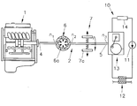
- the figure shows an internal combustion engine 1, which is connected via a drive train 2 to an expander 13 of a heat recovery system 10 which, in addition to the expander 13, has at least one compressor 11, a heat exchanger 12 and a condenser 14.
- the organic working medium for example, is compressed via the compressor 11, and the waste heat from the internal combustion engine 1, for example from the exhaust gas, is fed into the heat exchanger 12.
- the working medium is released with the release of mechanical work and cooled in the condenser 14.
- the expander 13 is formed by a working machine, for example a turbine or a reciprocating piston machine.
- Reference number 4 denotes the crankshaft, reference number 5 the output shaft of the expander 13.
- step-up or step-down gears between expander 13 and internal combustion engine 1 which are in principle in each of the three sections of the drive train (between crankshaft and shaft coupling, can be arranged between the shaft coupling and the braking device and between the braking device and expander) are not shown.
- a shaft clutch 6 designed as a one-way clutch (overrunning clutch) 6 a is arranged in the drive train 2.
- the one-way clutch 6a serves to prevent the expander 13 from being driven by the crankshaft 4 of the internal combustion engine 1.
- the drive train 2 is interrupted.
- the drive is only possible from the expander 13 to the internal combustion engine 1, but not in the opposite direction.
- a braking device 7 Arranged between the shaft coupling 6 and the expander 13 is a braking device 7, which is designed as an automatic centrifugal brake 7a. As soon as the current speed n 2 of the expander 13 reaches a defined critical speed n k , the output shaft 5 of the expander 13 is braked by the braking device 7, so that overextension of the expander 13 beyond this critical speed is avoided. Below the critical speed, the braking device 7 releases the output shaft 5, so that the expander 13 can rotate freely.
- the centrifugal brake keeps the current speed n 2 of the expander 13 below the critical speed n k of the expander 13 under all operating conditions of the engine, in particular also those with a high engine speed such as gear change or engine brake operation.
- the centrifugal brake 7a acts as a safety device for the expander 13, for example in the event that the mechanical connection in the drive train 2 between the expander 13 and the internal combustion engine 1 is interrupted (for example if a drive belt in the drive train fails).
Landscapes
- Engineering & Computer Science (AREA)
- Chemical & Material Sciences (AREA)
- Combustion & Propulsion (AREA)
- Mechanical Engineering (AREA)
- General Engineering & Computer Science (AREA)
- Engine Equipment That Uses Special Cycles (AREA)
Description
- Die Erfindung betrifft eine Brennkraftmaschine mit einem insbesondere nach dem organischen Rankine Zyklus arbeitenden Abwärmerückgewinnungssystem, welches zumindest einen Verdichter, zumindest einen Wärmetauscher, zumindest einen Expander und zumindest einen Kondensator aufweist, wobei eine Abtriebswelle des Expanders über einen zumindest eine Wellenkupplung aufweisenden Triebstrang mit einer Kurbelwelle der Brennkraftmaschine antriebsverbindbar ist, wobei der Triebstrang durch die Wellenkupplung unterbrechbar ist, sobald die brennkraftmaschinenseitige Drehzahl der Wellenkupplung die expanderseitige Drehzahl der Wellenkupplung überschreitet und wobei im Triebstrang zwischen dem Expander und der Brennkraftmaschine zumindest eine Bremseinrichtung angeordnet ist.
- Weiters betrifft die Erfindung ein Verfahren zum Betreiben einer Brennkraftmaschine, welche ein insbesondere nach dem organischen Rankine Zyklus arbeitendes Abwärmerückgewinnungssystem aufweist, wobei ein Arbeitsmedium in zumindest einem Verdichter komprimiert, in zumindest einen Wärmetauscher durch Abwärme insbesondere der Brennkraftmaschine erhitzt, in zumindest einem Expander unter Abgabe von Arbeit an die Kurbelwelle der Brennkraftmaschine expandiert und in zumindest einem Kondensator abgekühlt wird, wobei ein Triebstrang zwischen dem Expander und der Brennkraftmaschine mittels einer vorzugsweise als Freilaufkupplung ausgebildeten Wellenkupplung unterbrochen wird, wenn die brennkraftmaschinenseitige Drehzahl der Wellenkupplung die expanderseitige Drehzahl der Wellenkupplung überschreitet.
- Im Stand der Technik sind Vorrichtungen zur Abwärmenutzung einer Brennkraftmaschine bekannt, mit denen aus dem Abgas der Brennkraftmaschine Energie beispielsweise mittels eines organischen Rankine-Zyklus zurückgewonnen werden kann. Dabei wird ein organisches Arbeitsmedium durch eine Speisepumpe bzw. durch einen Verdichter verdichtet, in einem Wärmetauscher mittels der Abwärme der Brennkraftmaschine erhitzt, in einer beispielsweise als Turbine oder Kolbenmaschine ausgebildeten Arbeitsmaschine (Expander) unter Abgabe von Arbeit expandiert und in einem Kondensator abgekühlt. Die Arbeitsmaschine kann zur Stromerzeugung mit einem Generator verbunden sein oder zur Abgabe von mechanischer Antriebsleistung mit der Kurbelwelle der Brennkraftmaschine antriebsverbunden sein.
- Die
EP 1 243 758 A1 offenbart eine Brennkraftmaschine mit einem nach dem organischen Rankine-Zyklus arbeitenden Abwärmerückgewinnungssystem, welches einen Verdichter, einen Wärmetauscher, einen Expander und einen Kondensator aufweist. Die Abtriebswelle des Expanders ist über zumindest einen Wellenkupplung mit der Kurbelwelle der Brennkraftmaschine antriebverbindbar. Zwischen dem Expander und der Brennkraftmaschine ist im Triebstrang eine Bremseinrichtung angeordnet. - Aus der
DE 20 2013 004 907 U1 ist ein Kraftfahrzeug mit einer koppelbaren Abwärmenutzungsanordnung bekannt, wobei die Arbeitsmaschine des Kreisprozesses über Kupplungen wahlweise mit einer Brennkraftmaschine oder einem Nebenaggregat über ein Zugmittelgetriebe antriebsverbunden werden kann. Weiters ist zwischen der Arbeitsmaschine und dem Zugmittelgetriebe ein Freilauf angeordnet. - Die
DE 10 2010 025 186 A1 beschreibt eine Abwärmenutzungsvorrichtung für eine Brennkraftmaschine mit einem eine Expansionsmaschine aufweisenden Abwärmenutzungskreis, in welchem ein Arbeitsmedium zirkuliert. Die Expansionsmaschine ist über eine Überholkupplung mit der Kurbelwelle der Brennkraftmaschine verbunden. Eine derartige Überholkupplung erlaubt eine Antriebskraftübertragung ausschließlich von der Expansionsmaschine zur Kurbelwelle. Somit wird ein Schleppen der Expansionsmaschine durch die Kurbelwelle vermieden. - In gewissen Betriebsbereichen kann es allerdings vorkommen, dass trotzdem die Expanderdrehzahl die maximal zulässige Drehzahl des Expanders überschreitet, beispielsweise wenn die zulässige Expanderdrehzahl unter der zulässigen maximalen Motordrehzahl liegt, oder auch im Falle eines Defektes im Triebstrang.
- Aufgabe der Erfindung ist es, ein Überdrehen des Expanders zuverlässig und mit geringem konstruktivem Aufwand zu vermeiden.
- Erfindungsgemäß wird dies dadurch erreicht, dass der Expander durch die Bremseinrichtung abbremsbar ist, wenn die Drehzahl des Expanders eine definierte kritische Grenzdrehzahl des Expanders überschreitet.
- Vorzugsweise ist die Bremseinrichtung im Triebstrang zwischen dem Expander und der Wellenkupplung angeordnet.
- Die Bremseinrichtung kann als steuerbare bzw. regelbare Bremseinrichtung ausgebildet sein. In einer besonders einfachen Ausführung der Erfindung ist allerdings vorgesehen, dass die Bremseinrichtung als Fliehkraftbremse ausgebildet ist. Fliehkraftbremsen haben den Vorteil, dass sie selbsttätig agieren und die entsprechende anliegende Welle ab einer definierten Drehzahl abbremsen.
- Weiters ist es vorteilhaft, wenn die Wellenkupplung als Freilaufkupplung ausgebildet ist. Dadurch kann der Triebstrang durch die Wellenkupplung selbsttätig unterbrochen werden, sobald die brennkraftmaschinenseitige Drehzahl der Wellenkupplung die expanderseitige Drehzahl der Wellenkupplung überschreitet.
- Fliehkraftbremse und Freilaufkupplung arbeiten völlig autark, sodass separate Steuereinrichtungen und Aktuatoren entfallen können.
- Das Abwärmerückgewinnungssystem arbeitet bevorzugt nach dem bekannten Organischen Rankine Zyklus, wobei ein organisches Arbeitsmedium in zumindest einem Verdichter komprimiert, in zumindest einen Wärmetauscher durch Abwärme der Brennkraftmaschine erhitzt, in zumindest einem Expander unter Abgabe von Arbeit an die Kurbelwelle der Brennkraftmaschine expandiert und in zumindest einem Kondensator abgekühlt wird. Der Triebstrang zwischen dem Expander und der Brennkraftmaschine wird mittels der vorzugsweise als Freilaufkupplung ausgebildeten Wellenkupplung unterbrochen, wenn die brennkraftmaschinenseitige Drehzahl der Wellenkupplung die expanderseitige Drehzahl der Wellenkupplung überschreitet.
- Gemäß dem erfindungsgemäßen Verfahren ist zur Vermeidung einer Überdrehzahl des Expanders vorgesehen, dass der Triebstrang auf der Expanderseite der Wellenkupplung über die vorzugsweise als Fliehkraftbremse ausgebildete Bremseinrichtung abgebremst wird, wenn die Drehzahl des Expanders eine definierte kritische Grenzdrehzahl überschreitet.
- Die Erfindung wird im Folgenden anhand eines nicht einschränkenden Ausführungsbeispiels näher erläutert.
- Die Figur zeigt eine Brennkraftmaschine 1, welche über einen Triebstrang 2 mit einem Expander 13 eines Wärmerückgewinnungssystems 10 verbunden ist, welches neben dem Expander 13 zumindest einen Verdichters 11, einen Wärmetauscher 12 und einen Kondensator 14 aufweist. Über den Verdichter 11 wird das beispielsweise organische Arbeitsmedium verdichtet, im Wärmetauscher 12 die Abwärme der Brennkraftmaschine 1, beispielsweise aus dem Abgas, zugeführt. Im Expander wird das Arbeitsmedium unter Abgabe von mechanischer Arbeit entspannt und im Kondensator 14 abgekühlt. Der Expander 13 wird durch eine Arbeitsmaschine, beispielsweise eine Turbine oder eine Hubkolbenmaschine gebildet. Mit Bezugszeichen 4 ist die Kurbelwelle, mit Bezugszeichen 5 die Abtriebswelle des Expanders 13 bezeichnet. Eventuell vorhandene Über- oder Untersetzungsgetriebe zwischen Expander 13 und Brennkraftmaschine 1, die prinzipiell in jedem der drei Abschnitte des Triebstranges (zwischen Kurbelwelle und Wellenkupplung, zwischen Wellenkupplung und Bremseinrichtung sowie zwischen Bremseinrichtung und Expander) angeordnet sein können, sind nicht dargestellt.
- Im Triebstrang 2 ist eine als Freilaufkupplung (Überholkupplung) 6a ausgebildete Wellenkupplung 6 angeordnet. Die Freilaufkupplung 6a dient dazu, einen Antrieb des Expanders 13 durch die Kurbelwelle 4 der Brennkraftmaschine 1 zu vermeiden. Sobald die brennkraftmaschinenseitige Drehzahl n1 der Freilaufkupplung 6a größer ist, als die expanderseitige Drehzahl n2 der Freilaufkupplung 6a, wird der Triebstrang 2 unterbrochen. Somit ist der Antrieb nur vom Expander 13 zur Brennkraftmaschine 1, aber nicht in umgekehrter Richtung, möglich.
- Zwischen der Wellenkupplung 6 und dem Expander 13 ist eine Bremseinrichtung 7 angeordnet, welche als selbsttätige Fliehkraftbremse 7a ausgebildet ist. Sobald die aktuelle Drehzahl n2 des Expanders 13 eine definierte kritische Drehzahl nk erreicht, wird die Abtriebswelle 5 des Expanders 13 durch die Bremseinrichtung 7 abgebremst, sodass ein Überdrehen des Expanders 13 über diese kritische Drehzahl hinaus vermieden wird. Unterhalb der kritischen Drehzahl gibt die Bremseinrichtung 7 die Abtriebswelle 5 frei, sodass ein unbehindertes Drehen des Expanders 13 möglich ist.
- Durch die Fliehkraftbremse wird die aktuelle Drehzahl n2 des Expanders 13, unter allen Betriebszuständen des Motors, insbesondere auch solchen mit hoher Motordrehzahl wie Gangwechsel oder Motorbremsbetrieb, unterhalb der kritischen Drehzahl nk des Expanders 13 gehalten. Zusätzlich agiert die Fliehkraftbremse 7a als Sicherheitseinrichtung für den Expander 13, beispielsweise für den Fall, dass die mechanische Verbindung im Triebstrang 2 zwischen dem Expander 13 und der Brennkraftmaschine 1 unterbrochen wird (zum Beispiel bei Versagen eines Antriebsriemens im Triebstrang).
Claims (6)
- Brennkraftmaschine (1) mit einem insbesondere nach dem organischen Rankine Zyklus arbeitenden Abwärmerückgewinnungssystem (10), welches zumindest einen Verdichter (11), zumindest einen Wärmetauscher (12), zumindest einen Expander (13) und zumindest einen Kondensator (14) aufweist, wobei eine Abtriebswelle (5) des Expanders (13) über einen zumindest eine Wellenkupplung (6) aufweisenden Triebstrang (2) mit einer Kurbelwelle (4) der Brennkraftmaschine (1) antriebsverbindbar ist, wobei im Triebstrang (2) zwischen dem Expander (13) und der Brennkraftmaschine (1) zumindest eine Bremseinrichtung (7) angeordnet ist, dadurch gekennzeichnet, dass die Bremseinrichtung (7) dazu ausgelegt ist den Expander (13) abzubremsen, wenn die Drehzahl (n2) des Expanders (13) eine definierte kritische Grenzdrehzahl (nk) des Expanders (13) überschreitet.
- Brennkraftmaschine (1) nach Anspruch 1, dadurch gekennzeichnet, dass die Bremseinrichtung (7) im Triebstrang (2) zwischen dem Expander (13) und der Wellenkupplung (6) angeordnet ist.
- Brennkraftmaschine (1) nach Anspruch 1 oder 2, dadurch gekennzeichnet, dass der Triebstrang (2) durch die Wellenkupplung (6) unterbrechbar ist, sobald die brennkraftmaschinenseitige Drehzahl (n1) der Wellenkupplung (6) die expanderseitige Drehzahl (n2) der Wellenkupplung (6) überschreitet.
- Brennkraftmaschine (1) nach einem der Ansprüche 1 bis 3, dadurch gekennzeichnet, dass die Wellenkupplung (6) als Freilaufkupplung (6a) ausgebildet ist.
- Brennkraftmaschine (1) nach einem der Ansprüche 1 bis 4, dadurch gekennzeichnet, dass die Bremseinrichtung (7) als Fliehkraftbremse (7a) ausgebildet ist.
- Verfahren zum Betreiben einer Brennkraftmaschine (1), welche ein insbesondere nach dem organischen Rankine Zyklus arbeitendes Abwärmerückgewinnungssystem (10) aufweist, wobei ein Arbeitsmedium in zumindest einem Verdichter (11) komprimiert, in zumindest einem Wärmetauscher (12) durch Abwärme insbesondere der Brennkraftmaschine (1) erhitzt, in zumindest einem Expander (13) unter Abgabe von Arbeit an die Kurbelwelle (4) der Brennkraftmaschine (1) expandiert und in zumindest einem Kondensator (14) abgekühlt wird, wobei ein Triebstrang (2) zwischen dem Expander (13) und der Brennkraftmaschine (1) mittels einer vorzugsweise als Freilaufkupplung (6a) ausgebildeten Wellenkupplung (6) unterbrochen wird, wenn die brennkraftmaschinenseitige Drehzahl (n1) der Wellenkupplung (6) die expanderseitige Drehzahl (n2) der Wellenkupplung (6) überschreitet, dadurch gekennzeichnet, dass der Triebstrang (2) auf der Expanderseite der Wellenkupplung (6) über eine vorzugsweise als Fliehkraftbremse (7a) ausgebildete Bremseinrichtung (7) abgebremst wird, wenn die aktuelle Drehzahl (n2) des Expanders (13) eine definierte kritische Grenzdrehzahl (nk) des Expanders (13) überschreitet.
Applications Claiming Priority (2)
| Application Number | Priority Date | Filing Date | Title |
|---|---|---|---|
| ATA50487/2015A AT516709B1 (de) | 2015-06-15 | 2015-06-15 | Brennkraftmaschine mit einem abwärmerückgewinnungssystem |
| PCT/AT2016/050138 WO2016201460A1 (de) | 2015-06-15 | 2016-05-12 | Brennkraftmaschine mit einem abwärmerückgewinnungssystem |
Publications (2)
| Publication Number | Publication Date |
|---|---|
| EP3307993A1 EP3307993A1 (de) | 2018-04-18 |
| EP3307993B1 true EP3307993B1 (de) | 2020-06-24 |
Family
ID=56403916
Family Applications (1)
| Application Number | Title | Priority Date | Filing Date |
|---|---|---|---|
| EP16736766.3A Not-in-force EP3307993B1 (de) | 2015-06-15 | 2016-05-12 | Brennkraftmaschine mit einem abwärmerückgewinnungssystem |
Country Status (3)
| Country | Link |
|---|---|
| EP (1) | EP3307993B1 (de) |
| AT (1) | AT516709B1 (de) |
| WO (1) | WO2016201460A1 (de) |
Families Citing this family (3)
| Publication number | Priority date | Publication date | Assignee | Title |
|---|---|---|---|---|
| DE102015224128A1 (de) * | 2015-12-03 | 2017-06-08 | Robert Bosch Gmbh | Abwärmerückgewinnungssystem einer Brennkraftmaschine und Verfahren zum Betreiben eines Abwärmerückgewinnungssystems einer Brennkraftmaschine |
| DE102016219604A1 (de) * | 2016-10-10 | 2018-04-12 | Mahle International Gmbh | Drehschwingungsdämpfer |
| CN115077139B (zh) * | 2021-03-16 | 2024-06-21 | 浙江雪波蓝科技有限公司 | 朗肯-制冷循环系统及冷藏车 |
Family Cites Families (9)
| Publication number | Priority date | Publication date | Assignee | Title |
|---|---|---|---|---|
| JP2001227616A (ja) * | 1999-12-08 | 2001-08-24 | Honda Motor Co Ltd | 駆動装置 |
| DE102010025186A1 (de) | 2010-06-26 | 2011-04-28 | Daimler Ag | Abwärmenutzungsvorrichtung, Brennkraftmaschine und Kraftfahrzeug |
| WO2012025775A1 (en) * | 2010-08-27 | 2012-03-01 | Renault Trucks | Engine arrangement comprising a heat recovery circuit |
| JP5761358B2 (ja) * | 2011-09-30 | 2015-08-12 | 日産自動車株式会社 | ランキンサイクル |
| JP5741524B2 (ja) * | 2011-10-19 | 2015-07-01 | 株式会社豊田自動織機 | ランキンサイクル |
| DE102012220893A1 (de) * | 2012-11-15 | 2014-05-15 | Zf Friedrichshafen Ag | Fahrzeugantrieb mit einem Verbrennungsmotor und einer Abwärmenutzungseinheit |
| DE102013103829A1 (de) * | 2013-04-16 | 2014-10-16 | Robert Bosch Gmbh | Rekuperationssystem für ein Kraftfahrzeug |
| DE202013004907U1 (de) | 2013-05-28 | 2013-07-02 | GM Global Technology Operations LLC (n. d. Ges. d. Staates Delaware) | Kraftfahrzeug mit einer koppelbaren Abwärmenutzanordnung |
| DE102013009219A1 (de) * | 2013-05-31 | 2014-12-04 | Man Truck & Bus Ag | Verfahren und Vorrichtung zum Betreiben einer Brennkraftmaschine |
-
2015
- 2015-06-15 AT ATA50487/2015A patent/AT516709B1/de not_active IP Right Cessation
-
2016
- 2016-05-12 EP EP16736766.3A patent/EP3307993B1/de not_active Not-in-force
- 2016-05-12 WO PCT/AT2016/050138 patent/WO2016201460A1/de not_active Ceased
Non-Patent Citations (1)
| Title |
|---|
| None * |
Also Published As
| Publication number | Publication date |
|---|---|
| WO2016201460A1 (de) | 2016-12-22 |
| AT516709B1 (de) | 2016-08-15 |
| AT516709A4 (de) | 2016-08-15 |
| EP3307993A1 (de) | 2018-04-18 |
Similar Documents
| Publication | Publication Date | Title |
|---|---|---|
| DE102012000314B4 (de) | Reibungsanfahrstrategie für einen Kraftfahrzeug-Antriebsstrang | |
| WO2013131642A1 (de) | Abwärmenutzungsvorrichtung für ein kraftfahrzeug | |
| EP2684728B1 (de) | Kraftfahrzeug mit von einem elektromotor angetriebenen nebenaggregaten | |
| EP2178730B1 (de) | Verfahren zur durchführung einer zugkraftunterbrochenen schaltung bei einem parallelen hybridfahrzeug | |
| EP3307993B1 (de) | Brennkraftmaschine mit einem abwärmerückgewinnungssystem | |
| EP2698505A1 (de) | Verfahren zum Laden und Entladen eines Wärmespeichers und Anlage zur Speicherung und Abgabe von thermischer Energie, geeignet für dieses Verfahren | |
| EP2556217A2 (de) | Kraftwerksstrang mit einer drehzahlvariablen pumpe | |
| WO2011012259A1 (de) | Getriebeölkreislauf | |
| EP1911622A1 (de) | Antrieb für ein Kettenfahrzeug | |
| DE102012019967B4 (de) | Aufladeeinrichtung für Brennkraftmaschinen | |
| EP4061676A1 (de) | Vorrichtung und verfahren zur energierückgewinnung für ein elektrisch angetriebenes kraftfahrzeug | |
| WO2012156175A2 (de) | Vorrichtung und verfahren zur nutzung der abwärme einer brennkraftmaschine | |
| EP2527635A2 (de) | Energierückgewinnungssystem | |
| DE102012213277A1 (de) | Verfahren zum Durchführen einer Fahrtrichtungsumkehr bei Arbeitsmaschinen | |
| EP2050641B1 (de) | Hybridfahrzeug | |
| DE102008054164A1 (de) | Kupplungskompressor- und Lenkhilfepumpenanordnung sowie Verfahren zu deren Steuerung | |
| DE102016218764A1 (de) | Brennkraftmaschine eines Kraftfahrzeugs mit einer Abwärmenutzungseinrichtung | |
| EP2963256A1 (de) | Antriebseinrichtung für ein kraftfahrzeug | |
| DE102008040587B4 (de) | Antriebsanordnung für ein Kraftfahrzeug, sowie Verfahren zum Betrieb einer Antriebsanordnung für ein Kraftfahrzeug | |
| DE102012220893A1 (de) | Fahrzeugantrieb mit einem Verbrennungsmotor und einer Abwärmenutzungseinheit | |
| DE102013103829A1 (de) | Rekuperationssystem für ein Kraftfahrzeug | |
| WO2012159830A1 (de) | Hybridfahrzeug und verfahren zum betreiben eines hybridfahrzeugs | |
| DE102012020821B4 (de) | Notantrieb für ein Baugerät und Verfahren zum Betrieb des Notantriebs | |
| DE102006043518A1 (de) | Autarke Energieerzeugungseinheit für ein von einer Verbrennungskraftmaschine angetriebenes Fahrzeug | |
| DE102019134552A1 (de) | Verfahren zur Bestimmung einer Nachkühlzeit für einen ein Fahrzeug antreibenden Elektro-Traktionsmotor |
Legal Events
| Date | Code | Title | Description |
|---|---|---|---|
| STAA | Information on the status of an ep patent application or granted ep patent |
Free format text: STATUS: THE INTERNATIONAL PUBLICATION HAS BEEN MADE |
|
| PUAI | Public reference made under article 153(3) epc to a published international application that has entered the european phase |
Free format text: ORIGINAL CODE: 0009012 |
|
| STAA | Information on the status of an ep patent application or granted ep patent |
Free format text: STATUS: REQUEST FOR EXAMINATION WAS MADE |
|
| 17P | Request for examination filed |
Effective date: 20171204 |
|
| AK | Designated contracting states |
Kind code of ref document: A1 Designated state(s): AL AT BE BG CH CY CZ DE DK EE ES FI FR GB GR HR HU IE IS IT LI LT LU LV MC MK MT NL NO PL PT RO RS SE SI SK SM TR |
|
| AX | Request for extension of the european patent |
Extension state: BA ME |
|
| DAV | Request for validation of the european patent (deleted) | ||
| DAX | Request for extension of the european patent (deleted) | ||
| GRAP | Despatch of communication of intention to grant a patent |
Free format text: ORIGINAL CODE: EPIDOSNIGR1 |
|
| STAA | Information on the status of an ep patent application or granted ep patent |
Free format text: STATUS: GRANT OF PATENT IS INTENDED |
|
| INTG | Intention to grant announced |
Effective date: 20200310 |
|
| GRAS | Grant fee paid |
Free format text: ORIGINAL CODE: EPIDOSNIGR3 |
|
| GRAA | (expected) grant |
Free format text: ORIGINAL CODE: 0009210 |
|
| STAA | Information on the status of an ep patent application or granted ep patent |
Free format text: STATUS: THE PATENT HAS BEEN GRANTED |
|
| AK | Designated contracting states |
Kind code of ref document: B1 Designated state(s): AL AT BE BG CH CY CZ DE DK EE ES FI FR GB GR HR HU IE IS IT LI LT LU LV MC MK MT NL NO PL PT RO RS SE SI SK SM TR |
|
| REG | Reference to a national code |
Ref country code: GB Ref legal event code: FG4D Free format text: NOT ENGLISH |
|
| REG | Reference to a national code |
Ref country code: CH Ref legal event code: EP |
|
| REG | Reference to a national code |
Ref country code: AT Ref legal event code: REF Ref document number: 1284100 Country of ref document: AT Kind code of ref document: T Effective date: 20200715 |
|
| REG | Reference to a national code |
Ref country code: DE Ref legal event code: R096 Ref document number: 502016010321 Country of ref document: DE |
|
| REG | Reference to a national code |
Ref country code: IE Ref legal event code: FG4D Free format text: LANGUAGE OF EP DOCUMENT: GERMAN |
|
| PG25 | Lapsed in a contracting state [announced via postgrant information from national office to epo] |
Ref country code: NO Free format text: LAPSE BECAUSE OF FAILURE TO SUBMIT A TRANSLATION OF THE DESCRIPTION OR TO PAY THE FEE WITHIN THE PRESCRIBED TIME-LIMIT Effective date: 20200924 Ref country code: SE Free format text: LAPSE BECAUSE OF FAILURE TO SUBMIT A TRANSLATION OF THE DESCRIPTION OR TO PAY THE FEE WITHIN THE PRESCRIBED TIME-LIMIT Effective date: 20200624 Ref country code: FI Free format text: LAPSE BECAUSE OF FAILURE TO SUBMIT A TRANSLATION OF THE DESCRIPTION OR TO PAY THE FEE WITHIN THE PRESCRIBED TIME-LIMIT Effective date: 20200624 Ref country code: GR Free format text: LAPSE BECAUSE OF FAILURE TO SUBMIT A TRANSLATION OF THE DESCRIPTION OR TO PAY THE FEE WITHIN THE PRESCRIBED TIME-LIMIT Effective date: 20200925 Ref country code: LT Free format text: LAPSE BECAUSE OF FAILURE TO SUBMIT A TRANSLATION OF THE DESCRIPTION OR TO PAY THE FEE WITHIN THE PRESCRIBED TIME-LIMIT Effective date: 20200624 |
|
| REG | Reference to a national code |
Ref country code: LT Ref legal event code: MG4D |
|
| PG25 | Lapsed in a contracting state [announced via postgrant information from national office to epo] |
Ref country code: RS Free format text: LAPSE BECAUSE OF FAILURE TO SUBMIT A TRANSLATION OF THE DESCRIPTION OR TO PAY THE FEE WITHIN THE PRESCRIBED TIME-LIMIT Effective date: 20200624 Ref country code: HR Free format text: LAPSE BECAUSE OF FAILURE TO SUBMIT A TRANSLATION OF THE DESCRIPTION OR TO PAY THE FEE WITHIN THE PRESCRIBED TIME-LIMIT Effective date: 20200624 Ref country code: LV Free format text: LAPSE BECAUSE OF FAILURE TO SUBMIT A TRANSLATION OF THE DESCRIPTION OR TO PAY THE FEE WITHIN THE PRESCRIBED TIME-LIMIT Effective date: 20200624 Ref country code: BG Free format text: LAPSE BECAUSE OF FAILURE TO SUBMIT A TRANSLATION OF THE DESCRIPTION OR TO PAY THE FEE WITHIN THE PRESCRIBED TIME-LIMIT Effective date: 20200924 |
|
| REG | Reference to a national code |
Ref country code: NL Ref legal event code: MP Effective date: 20200624 |
|
| PG25 | Lapsed in a contracting state [announced via postgrant information from national office to epo] |
Ref country code: NL Free format text: LAPSE BECAUSE OF FAILURE TO SUBMIT A TRANSLATION OF THE DESCRIPTION OR TO PAY THE FEE WITHIN THE PRESCRIBED TIME-LIMIT Effective date: 20200624 Ref country code: AL Free format text: LAPSE BECAUSE OF FAILURE TO SUBMIT A TRANSLATION OF THE DESCRIPTION OR TO PAY THE FEE WITHIN THE PRESCRIBED TIME-LIMIT Effective date: 20200624 |
|
| PG25 | Lapsed in a contracting state [announced via postgrant information from national office to epo] |
Ref country code: RO Free format text: LAPSE BECAUSE OF FAILURE TO SUBMIT A TRANSLATION OF THE DESCRIPTION OR TO PAY THE FEE WITHIN THE PRESCRIBED TIME-LIMIT Effective date: 20200624 Ref country code: SM Free format text: LAPSE BECAUSE OF FAILURE TO SUBMIT A TRANSLATION OF THE DESCRIPTION OR TO PAY THE FEE WITHIN THE PRESCRIBED TIME-LIMIT Effective date: 20200624 Ref country code: PT Free format text: LAPSE BECAUSE OF FAILURE TO SUBMIT A TRANSLATION OF THE DESCRIPTION OR TO PAY THE FEE WITHIN THE PRESCRIBED TIME-LIMIT Effective date: 20201026 Ref country code: EE Free format text: LAPSE BECAUSE OF FAILURE TO SUBMIT A TRANSLATION OF THE DESCRIPTION OR TO PAY THE FEE WITHIN THE PRESCRIBED TIME-LIMIT Effective date: 20200624 Ref country code: CZ Free format text: LAPSE BECAUSE OF FAILURE TO SUBMIT A TRANSLATION OF THE DESCRIPTION OR TO PAY THE FEE WITHIN THE PRESCRIBED TIME-LIMIT Effective date: 20200624 Ref country code: ES Free format text: LAPSE BECAUSE OF FAILURE TO SUBMIT A TRANSLATION OF THE DESCRIPTION OR TO PAY THE FEE WITHIN THE PRESCRIBED TIME-LIMIT Effective date: 20200624 |
|
| PG25 | Lapsed in a contracting state [announced via postgrant information from national office to epo] |
Ref country code: SK Free format text: LAPSE BECAUSE OF FAILURE TO SUBMIT A TRANSLATION OF THE DESCRIPTION OR TO PAY THE FEE WITHIN THE PRESCRIBED TIME-LIMIT Effective date: 20200624 Ref country code: PL Free format text: LAPSE BECAUSE OF FAILURE TO SUBMIT A TRANSLATION OF THE DESCRIPTION OR TO PAY THE FEE WITHIN THE PRESCRIBED TIME-LIMIT Effective date: 20200624 Ref country code: IS Free format text: LAPSE BECAUSE OF FAILURE TO SUBMIT A TRANSLATION OF THE DESCRIPTION OR TO PAY THE FEE WITHIN THE PRESCRIBED TIME-LIMIT Effective date: 20201024 |
|
| REG | Reference to a national code |
Ref country code: DE Ref legal event code: R097 Ref document number: 502016010321 Country of ref document: DE |
|
| PG25 | Lapsed in a contracting state [announced via postgrant information from national office to epo] |
Ref country code: DK Free format text: LAPSE BECAUSE OF FAILURE TO SUBMIT A TRANSLATION OF THE DESCRIPTION OR TO PAY THE FEE WITHIN THE PRESCRIBED TIME-LIMIT Effective date: 20200624 |
|
| PLBE | No opposition filed within time limit |
Free format text: ORIGINAL CODE: 0009261 |
|
| STAA | Information on the status of an ep patent application or granted ep patent |
Free format text: STATUS: NO OPPOSITION FILED WITHIN TIME LIMIT |
|
| 26N | No opposition filed |
Effective date: 20210325 |
|
| PG25 | Lapsed in a contracting state [announced via postgrant information from national office to epo] |
Ref country code: SI Free format text: LAPSE BECAUSE OF FAILURE TO SUBMIT A TRANSLATION OF THE DESCRIPTION OR TO PAY THE FEE WITHIN THE PRESCRIBED TIME-LIMIT Effective date: 20200624 |
|
| REG | Reference to a national code |
Ref country code: CH Ref legal event code: PL |
|
| GBPC | Gb: european patent ceased through non-payment of renewal fee |
Effective date: 20210512 |
|
| PG25 | Lapsed in a contracting state [announced via postgrant information from national office to epo] |
Ref country code: MC Free format text: LAPSE BECAUSE OF FAILURE TO SUBMIT A TRANSLATION OF THE DESCRIPTION OR TO PAY THE FEE WITHIN THE PRESCRIBED TIME-LIMIT Effective date: 20200624 Ref country code: LI Free format text: LAPSE BECAUSE OF NON-PAYMENT OF DUE FEES Effective date: 20210531 Ref country code: LU Free format text: LAPSE BECAUSE OF NON-PAYMENT OF DUE FEES Effective date: 20210512 Ref country code: CH Free format text: LAPSE BECAUSE OF NON-PAYMENT OF DUE FEES Effective date: 20210531 |
|
| REG | Reference to a national code |
Ref country code: BE Ref legal event code: MM Effective date: 20210531 |
|
| PG25 | Lapsed in a contracting state [announced via postgrant information from national office to epo] |
Ref country code: IE Free format text: LAPSE BECAUSE OF NON-PAYMENT OF DUE FEES Effective date: 20210512 Ref country code: GB Free format text: LAPSE BECAUSE OF NON-PAYMENT OF DUE FEES Effective date: 20210512 |
|
| REG | Reference to a national code |
Ref country code: AT Ref legal event code: MM01 Ref document number: 1284100 Country of ref document: AT Kind code of ref document: T Effective date: 20210512 |
|
| PG25 | Lapsed in a contracting state [announced via postgrant information from national office to epo] |
Ref country code: BE Free format text: LAPSE BECAUSE OF NON-PAYMENT OF DUE FEES Effective date: 20210531 |
|
| PG25 | Lapsed in a contracting state [announced via postgrant information from national office to epo] |
Ref country code: AT Free format text: LAPSE BECAUSE OF NON-PAYMENT OF DUE FEES Effective date: 20210512 |
|
| P01 | Opt-out of the competence of the unified patent court (upc) registered |
Effective date: 20230505 |
|
| PG25 | Lapsed in a contracting state [announced via postgrant information from national office to epo] |
Ref country code: CY Free format text: LAPSE BECAUSE OF FAILURE TO SUBMIT A TRANSLATION OF THE DESCRIPTION OR TO PAY THE FEE WITHIN THE PRESCRIBED TIME-LIMIT Effective date: 20200624 |
|
| PG25 | Lapsed in a contracting state [announced via postgrant information from national office to epo] |
Ref country code: HU Free format text: LAPSE BECAUSE OF FAILURE TO SUBMIT A TRANSLATION OF THE DESCRIPTION OR TO PAY THE FEE WITHIN THE PRESCRIBED TIME-LIMIT; INVALID AB INITIO Effective date: 20160512 |
|
| PGFP | Annual fee paid to national office [announced via postgrant information from national office to epo] |
Ref country code: IT Payment date: 20230531 Year of fee payment: 8 Ref country code: FR Payment date: 20230530 Year of fee payment: 8 Ref country code: DE Payment date: 20230531 Year of fee payment: 8 |
|
| PG25 | Lapsed in a contracting state [announced via postgrant information from national office to epo] |
Ref country code: MK Free format text: LAPSE BECAUSE OF FAILURE TO SUBMIT A TRANSLATION OF THE DESCRIPTION OR TO PAY THE FEE WITHIN THE PRESCRIBED TIME-LIMIT Effective date: 20200624 |
|
| PG25 | Lapsed in a contracting state [announced via postgrant information from national office to epo] |
Ref country code: MT Free format text: LAPSE BECAUSE OF FAILURE TO SUBMIT A TRANSLATION OF THE DESCRIPTION OR TO PAY THE FEE WITHIN THE PRESCRIBED TIME-LIMIT Effective date: 20200624 |
|
| REG | Reference to a national code |
Ref country code: DE Ref legal event code: R119 Ref document number: 502016010321 Country of ref document: DE |
|
| PG25 | Lapsed in a contracting state [announced via postgrant information from national office to epo] |
Ref country code: DE Free format text: LAPSE BECAUSE OF NON-PAYMENT OF DUE FEES Effective date: 20241203 |
|
| PG25 | Lapsed in a contracting state [announced via postgrant information from national office to epo] |
Ref country code: FR Free format text: LAPSE BECAUSE OF NON-PAYMENT OF DUE FEES Effective date: 20240531 |
|
| PG25 | Lapsed in a contracting state [announced via postgrant information from national office to epo] |
Ref country code: IT Free format text: LAPSE BECAUSE OF NON-PAYMENT OF DUE FEES Effective date: 20240512 |
|
| PG25 | Lapsed in a contracting state [announced via postgrant information from national office to epo] |
Ref country code: TR Free format text: LAPSE BECAUSE OF FAILURE TO SUBMIT A TRANSLATION OF THE DESCRIPTION OR TO PAY THE FEE WITHIN THE PRESCRIBED TIME-LIMIT Effective date: 20200624 |