EP3307397B1 - Self-braking pulley - Google Patents
Self-braking pulley Download PDFInfo
- Publication number
- EP3307397B1 EP3307397B1 EP16736000.7A EP16736000A EP3307397B1 EP 3307397 B1 EP3307397 B1 EP 3307397B1 EP 16736000 A EP16736000 A EP 16736000A EP 3307397 B1 EP3307397 B1 EP 3307397B1
- Authority
- EP
- European Patent Office
- Prior art keywords
- spool
- pawl
- pulley
- braking
- rotation
- Prior art date
- Legal status (The legal status is an assumption and is not a legal conclusion. Google has not performed a legal analysis and makes no representation as to the accuracy of the status listed.)
- Active
Links
Images


Classifications
-
- A—HUMAN NECESSITIES
- A62—LIFE-SAVING; FIRE-FIGHTING
- A62B—DEVICES, APPARATUS OR METHODS FOR LIFE-SAVING
- A62B35/00—Safety belts or body harnesses; Similar equipment for limiting displacement of the human body, especially in case of sudden changes of motion
- A62B35/0093—Fall arrest reel devices
-
- A—HUMAN NECESSITIES
- A62—LIFE-SAVING; FIRE-FIGHTING
- A62B—DEVICES, APPARATUS OR METHODS FOR LIFE-SAVING
- A62B1/00—Devices for lowering persons from buildings or the like
- A62B1/06—Devices for lowering persons from buildings or the like by making use of rope-lowering devices
- A62B1/08—Devices for lowering persons from buildings or the like by making use of rope-lowering devices with brake mechanisms for the winches or pulleys
- A62B1/10—Devices for lowering persons from buildings or the like by making use of rope-lowering devices with brake mechanisms for the winches or pulleys mechanically operated
-
- A—HUMAN NECESSITIES
- A62—LIFE-SAVING; FIRE-FIGHTING
- A62B—DEVICES, APPARATUS OR METHODS FOR LIFE-SAVING
- A62B35/00—Safety belts or body harnesses; Similar equipment for limiting displacement of the human body, especially in case of sudden changes of motion
- A62B35/04—Safety belts or body harnesses; Similar equipment for limiting displacement of the human body, especially in case of sudden changes of motion incorporating energy absorbing means
Definitions
- the present invention relates to a self-braking pulley.
- US2010/224448 A1 also discloses such a device, having a brake assembly comprising a shoe plate and brake shoes with brake pads and which is activated by a pawl mechanism.
- a self-braking pulley for controlling a rate of extraction of a tether coupled with the pulley, the pulley comprising: a spool for receiving a tether, the spool being arranged to rotate about an axle of the pulley as the tether is removed therefrom;
- the braking assembly is arranged to limit the rate of rotation of the spool and thus the rate of descent of a user, thereby minimising any sudden jolts and prolonged periods where the user may otherwise be held suspended above a floor, for example.
- the pawl may be arranged to pivot in a plane in which the wheel extends
- the pulley further comprises an elastic member which is coupled at one end to the spool and at the other end to the distal end of the pawl, for controlling the rotation of the pawl about the pivot.
- an elastic member which is coupled at one end to the spool and at the other end to the distal end of the pawl, for controlling the rotation of the pawl about the pivot.
- the elastic members are arranged to limit the rotation of each shoe about the respective hinged coupling to control the area of the brake pad which is arranged to contact the drum, in dependence of a rate of rotation of the plate.
- the self-braking pulley further comprises a housing for housing the spool, drive assembly, engagement member and braking assembly.
- the pulley axle and the axle of the braking assembly are preferably supported by the housing.
- the pulley further comprises at least one tether guide for guiding the tether to and from the spool.
- a self-braking pulley 100 for controlling a rate of extraction of a tether (not shown) wound upon the pulley 100. It is envisaged that this pulley 100 may be used for rapid descent from a height, such as when escaping from a building or a platform (not shown), or equally for arresting a fall of a person working at height.
- the controlled rate of descent offered by the pulley 100 further minimises any trauma which may otherwise be created following a prolonged suspension within a harness, for example.
- the self-braking pulley 100 comprises a housing having a first housing portion 110 which is arranged to house a spool 130 and drive assembly 140, and a second housing portion 120 which is arranged to house a braking assembly 150.
- the first housing portion 110 comprises a front and rear wall 111, 112 which are held in spaced relation by struts 113 which extend between the walls 111, 112 and which are secured to the walls 111, 112 by fasteners 114, such as a screw and bolts.
- the struts 113 are separated along a periphery of the first and second wall 111, 112.
- an anchor plate 115 which similarly extends between the front and rear wall 111, 112 thereof, and which is arranged to support an anchoring member 116, such as an eyelet, for enabling the pulley 100 to be secured to a suitable support (not shown).
- the second housing portion 120 is disposed at a front of the first housing portion 110 and comprises a substantially cylindrical drum 121, which is closed at a rear thereof by the front wall 111 of the first housing portion 110, and at the front thereof by a drum cover 122.
- the second housing portion 120 may further comprise a gasket or seal 123 (as illustrated in figure 5 of the drawings) which is arranged to extend between the cover 122 and the drum 121 to minimise any debris from passing into the drum 121.
- the drum 121 is secured to the front wall 111 of the first housing portion 110 and the cover is secured to the drum by a plurality of fasteners 124, such as screws and bolts.
- the spool 130 disposed within the first housing portion 110 is arranged to rotate about an axle 117 which extends between the front and rear wall 111, 112 of the first housing portion 110.
- the spool 130 is arranged to receive a tether, such as a rope (not shown), which may be wound upon the spool 130 and rotationally coupled therewith, such as by rigidly coupling one end of the tether to the spool 130.
- the other end of the tether is arranged to extend out from the first housing portion 110, such as at a lower region thereof, and is preferably guided out from the housing 110 by a guide spool 118 which is arranged to rotate about a guide axle 119 that extends between the front and rear walls 111, 112, at the lower region thereof.
- the spool 130 comprises a circumferentially extending groove 131 which extends radially inwardly of the spool.
- the groove 131 is defined by side walls 132 which converge in a direction which is radially inwardly of the spool 130 so that the tether becomes gripped by the spool 130 and thus rotationally coupled to the spool 130.
- the tether may be simply arranged to pass over the spool 130 (as opposed to being wound completely around the spool) such that the free ends of the tether extend out from the pulley 100 at opposite sides of the spool 130, and guided by a respective guide spool 118 (only one of which is illustrated in the drawings) disposed at the lower region of the first housing portion 110.
- the drive assembly 140 comprises a wheel 141 which is arranged to rotate about the axle 117 and comprises a plurality of serrations 142 disposed along a periphery thereof.
- the serrations 142 are asymmetric and separately comprise a long face 142a and a short face 142b which meet at an apex 142c, such that short face 142b forms a larger angle with a tangent to the wheel 141 than the long face 142a.
- the drive assembly 140 further comprises a pawl 143 which is pivotally coupled to a side of the spool 130, such that the pawl 143 is arranged to pivot in a plane which comprises the wheel 141.
- the pawl 143 comprises proximal end 143a which is disposed closer to the pivot 144 than the distal end 143b, and as such the centre of mass of the pawl 143 is disposed toward the side of the pivot 144 which extends toward the distal end 143b.
- the pawl 143 is further coupled to the spool 130 by an elastic member 145, such as a spring, which is coupled at one end to the distal end 143b of the pawl 143 and at the other end to the side of the spool 130.
- the pawl 143 is arranged to couple with the wheel 141 in dependence of the rotational speed of the spool 130, and thus the pawl 143 and wheel 141 collectively form a ratchet, as illustrated in figure 3 of the drawings.
- the drive assembly 140 further comprises a drive gear 146 disposed upon the axle 117, which is rotationally coupled with the wheel 141, such that the drive gear 146 rotates about the axle 117 in accordance with a rotation of the wheel 141.
- the braking assembly 150 of the pulley 100 comprises a shoe plate 151 which is arranged to rotate with an axle 152 that extends through the second housing portion 120.
- the axle 152 is supported in a bearing assembly (not shown) separately mounted within a cover 122 of the drum 121, a front wall 111 of the first housing portion 110 and the rear wall 112 of the first housing portion 110.
- the shoe plate 151 comprises a plurality of brake shoes 153 hingedly coupled thereto, along a periphery thereof.
- the brake shoes 153 are angularly separated around the plate 151 and are arranged to pivot about the respective hinge in a plane comprising the shoe plate 151.
- the brake shoes 153 separately comprise a bridging member 153a which extend over an outer perimeter of a portion of the shoe plate 151, and a pair of side walls 153b which extend radially inwardly of the shoe plate 151 from either side of the respective bridging member 153a.
- the bridging member 153a is arranged to support a brake pad 154 thereon, which faces radially outwardly of the shoe plate 151.
- Each brake shoe 153 is hingedly coupled at one end thereof to the shoe plate 151 via a pin 155 which extends between the side walls 153b through the plate 151.
- Each brake shoe 153 is hingedly coupled at the end of the shoe 153 which is the leading end of the shoe 153 as the plate 151 rotates within the drum 121 as the tether (not shown) is unwound from the spool 130.
- the braking assembly 150 further comprises a plurality of elastic members 156, such as springs, for controlling the rotation of the brake shoes 153 about the respective hinge, namely the pin 155.
- the springs 156 are coupled at one end to a trailing end of one brake shoe 153 and at the other end to the trailing end of an adjacent brake shoe 153. In this respect, the springs 156 ensure that the brake shoes 153 pivot about the respective pin 155 only once a minimum rate of rotation of the plate 151 is reached.
- the braking assembly 150 further comprises a brake lining 157 which is disposed along an inner side of the drum 121. In this respect, the drum 121 and lining 157 effectively form a brake drum to which the brake shoes 153 can contact to retard the rotation of the plate 151.
- the drive assembly 140 is coupled to the braking assembly 150 by a follower gear 160 which is rotationally coupled to the axle 152 of the braking assembly 150.
- the follower gear 160 is meshed with the drive gear 146 and as such the drive gear 146 and follower gear 160 are arranged to rotate together. Accordingly, in use, with the pulley 100 suitably anchored to a support (not shown) via the anchor member 116 and with a tether (not shown) wound upon the spool 130, a user desiring to exploit the self-braking facility of the pulley 100 would first secure the free end of the tether (not shown) to their harness (not shown) for example.
- the pawl 143 With the pulley 100 in this rest condition, the pawl 143 is arranged in the neutral condition, whereby the proximal end 143a of the pawl 143 is held separated from the serrations 142 on the wheel 141 by virtue of the weight of the pawl 143 being displaced to the one side of the pivot 144 and the restoring force of the spring 145.
- the tether (not shown) will begin to unwind from the spool 130 with an increasing rotational rate. As the rate of spool rotation increases, the pawl 143 will begin to rotate.
- the "heavy" distal end of the pawl 143 will rotate about the pivot 144 to a radially outer position of the spool 130 under the centrifugal force, thereby causing the proximal end 143a to rotate toward the serrations 142 on the wheel 141.
- a threshold will be reached whereby the proximal end 143a of the pawl 143 will locate with a short face 142b of a serration 142 on the wheel 141 and thus cause the wheel 141 to rotate with the spool 130, owing to the rotational coupling.
- the drive gear 146 will be rotate which subsequently causes the follower gear 160 to rotate.
- the driving of the follower gear 160 causes the shoe plate 151 to rotate within the brake drum 121. Accordingly, in a similar manner to the pawl 143, the brake shoes 153 pivot about the respective pin 155 under the centrifugal force created, thereby causing a leading edge of the brake pad 154 to contact the brake lining 157. As the rotational speed of the spool 130 and thus the shoe plate 151 increases, the brake shoes 153 will rotate further thereby bringing more surface area of the brake pad 154 into contact with the brake lining 157. This contact is arranged to limit the rotation of the spool 130 and thus the rate of extraction of the tether (not shown) therefrom to offer a controlled rate of decent of the user from their position of height.
- the ratchet formed within the drive assembly 140 only engages the braking assembly 150 when the spool 130 rotates in a particular direction.
- the spool 130 can thus be freely rotated in the opposite direction and as such in an alternative embodiment in which the free ends of the tether (not shown) extend out from the pulley 100, as opposed to one end of the tether being coupled to the spool 130, the pulley 100 can be used to lift a user or an item in a particular direction and control a rate of descent of the user or item in the opposite direction, owing to the rotational coupling of the tether to the spool 130 by the groove 131.
- the pulley 100 may comprise a separate drive assembly 140 and braking assembly 140 on opposite sides of the spool 130 for controlling the rate of rotation of the spool 130 in both rotational directions.
Landscapes
- Health & Medical Sciences (AREA)
- General Health & Medical Sciences (AREA)
- Business, Economics & Management (AREA)
- Emergency Management (AREA)
- Engineering & Computer Science (AREA)
- Mechanical Engineering (AREA)
- Braking Arrangements (AREA)
Description
- The present invention relates to a self-braking pulley.
- It is well known for individuals working or operating at height to use a tether to secure themselves to a suitable support to arrest their fall should they unexpectedly fall or otherwise need to escape from their position. The tether is typically secured to the individuals harness and as such, while the tether may arrest their fall, there can be a significant jolt upon the individual as the tether becomes taught. Moreover, once the individual has come to a rest and is held suspended from the tether it is necessary to lower the individual to avoid any trauma from prolonged suspension, particularly if the individual is unconscious and held in an inverted orientation.
- Known fall arrest devices are disclosed in
US2011/147125 A1 ,US2005/051659 A1 ,EP2845626 A1 ,US 5,351,906 A ,DE894354 C ,GB999552 A US4,591,029 A .US2010/224448 A1 also discloses such a device, having a brake assembly comprising a shoe plate and brake shoes with brake pads and which is activated by a pawl mechanism. - We have now devised a self-braking pulley.
- In accordance with the present invention there is provided a self-braking pulley for controlling a rate of extraction of a tether coupled with the pulley, the pulley comprising: a spool for receiving a tether, the spool being arranged to rotate about an axle of the pulley as the tether is removed therefrom;
- a braking assembly for applying a braking force to the spool, the braking assembly comprising a shoe plate, a follower gear and an axle, the shoe plate and the follower gear being rotationally coupled with the braking assembly axle such that rotation of the follower gear causes rotation of the shoe plate, the braking assembly further comprising a plurality of brake pads arranged to contact a brake drum in dependence of a rate of rotation of the spool about the pulley axle, each brake pad being separately disposed upon a respective brake shoe, each shoe being hingedly coupled at a leading end thereof during a rotation of the plate within the drum as the tether is unwound from the spool, to the shoe plate at angularly separate positions around the periphery thereof such that the contact area of the brake pads with the drum varies in dependence of a rate of rotation of the plate, a trailing end of each shoe being coupled via an elastic member to the trailing end of the rotationally adjacent shoe; and
- a drive assembly the drive assembly comprising a wheel having a plurality of serrations disposed along an outer perimeter thereof and a drive gear rotationally coupled with the wheel, the wheel and the drive gear being arranged to rotate about the pulley axle such that rotation of the wheel causes rotation of the drive gear, the drive gear further being rotationally coupled with the follower gear such that rotation of the drive gear causes rotation of the follower gear, the drive assembly being engagable with the spool via an engagement member comprising a pawl which is pivotally coupled to the spool about a pivot, the pawl having a centre of mass which is disposed to one side of the pivot, such that a proximate end of the pawl extends closer to the pivot than a distal end of the pawl, the pawl being reconfigurable from a neutral configuration in which the proximate end of the pawl extends away from the wheel to a drive configuration in which the proximate end of the pawl abuts the serrations on the wheel to rotationally couple the spool with the drive assembly for driving the braking assembly in dependence of a rate of rotation of the spool about the pulley axle.
- Advantageously, the braking assembly is arranged to limit the rate of rotation of the spool and thus the rate of descent of a user, thereby minimising any sudden jolts and prolonged periods where the user may otherwise be held suspended above a floor, for example.
- The pawl may be arranged to pivot in a plane in which the wheel extends
- In an embodiment, the pulley further comprises an elastic member which is coupled at one end to the spool and at the other end to the distal end of the pawl, for controlling the rotation of the pawl about the pivot. As the tether is unwound from the spool, the spool will rotate and the distal end of the pawl will begin to move in a radially outward direction of the spool owing to the increased mass of the pawl at the one side of the pivot. The elastic member is thus arranged to limit the rotation of the pawl about the pivot in dependence of the rotation of the spool.
- The elastic members are arranged to limit the rotation of each shoe about the respective hinged coupling to control the area of the brake pad which is arranged to contact the drum, in dependence of a rate of rotation of the plate.
- Preferably, the self-braking pulley further comprises a housing for housing the spool, drive assembly, engagement member and braking assembly. The pulley axle and the axle of the braking assembly are preferably supported by the housing.
- In an embodiment, the pulley further comprises at least one tether guide for guiding the tether to and from the spool.
- Whilst the invention has been described above, it extends to any inventive combination of features set out above or in the following description. Although illustrative embodiments of the invention are described in detail herein with reference to the accompanying drawings, it is to be understood that the invention is not limited to these precise embodiments.
- Furthermore, it is contemplated that a particular feature described either individually or as part of an embodiment can be combined with other individually described features, or parts of other embodiments, even if the other features and embodiments make no mention of the particular feature, within the scope of the appended claims.
- The invention may be performed in various ways, and, by way of example only, embodiments thereof will now be described, reference being made to the accompanying drawings in which:
-
Figure 1 is perspective view of a self-braking pulley according to an embodiment of the present invention; -
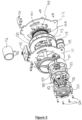
Figure 2 is a perspective view of the spool, drive assembly and braking assembly; -
Figure 3 is a magnified view of the pawl engaged with the wheel; -
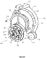
Figure 4 is a perspective view of the pulley illustrated infigure 1 , with the front wall of the first housing portion and the cover of the second housing portion, removed; -
Figure 5 is an exploded view of the pulley illustrated infigure 1 . - Referring to
figure 1 of the drawings, there is illustrated a self-braking pulley 100 according to an embodiment of the present invention, for controlling a rate of extraction of a tether (not shown) wound upon thepulley 100. It is envisaged that thispulley 100 may be used for rapid descent from a height, such as when escaping from a building or a platform (not shown), or equally for arresting a fall of a person working at height. The controlled rate of descent offered by thepulley 100 further minimises any trauma which may otherwise be created following a prolonged suspension within a harness, for example. - Referring to
figures 1 and2 of the drawings, the self-braking pulley 100 comprises a housing having afirst housing portion 110 which is arranged to house aspool 130 anddrive assembly 140, and asecond housing portion 120 which is arranged to house abraking assembly 150. Thefirst housing portion 110 comprises a front andrear wall 111, 112 which are held in spaced relation bystruts 113 which extend between thewalls 111, 112 and which are secured to thewalls 111, 112 byfasteners 114, such as a screw and bolts. Thestruts 113 are separated along a periphery of the first andsecond wall 111, 112. At an upper region of thefirst housing portion 110 there is provided ananchor plate 115 which similarly extends between the front andrear wall 111, 112 thereof, and which is arranged to support ananchoring member 116, such as an eyelet, for enabling thepulley 100 to be secured to a suitable support (not shown). - The
second housing portion 120 is disposed at a front of thefirst housing portion 110 and comprises a substantiallycylindrical drum 121, which is closed at a rear thereof by the front wall 111 of thefirst housing portion 110, and at the front thereof by adrum cover 122. Thesecond housing portion 120 may further comprise a gasket or seal 123 (as illustrated infigure 5 of the drawings) which is arranged to extend between thecover 122 and thedrum 121 to minimise any debris from passing into thedrum 121. In this respect, thedrum 121 is secured to the front wall 111 of thefirst housing portion 110 and the cover is secured to the drum by a plurality offasteners 124, such as screws and bolts. - The
spool 130 disposed within thefirst housing portion 110 is arranged to rotate about anaxle 117 which extends between the front andrear wall 111, 112 of thefirst housing portion 110. Thespool 130 is arranged to receive a tether, such as a rope (not shown), which may be wound upon thespool 130 and rotationally coupled therewith, such as by rigidly coupling one end of the tether to thespool 130. The other end of the tether is arranged to extend out from thefirst housing portion 110, such as at a lower region thereof, and is preferably guided out from thehousing 110 by aguide spool 118 which is arranged to rotate about aguide axle 119 that extends between the front andrear walls 111, 112, at the lower region thereof. - In an alternative embodiment, the
spool 130 comprises a circumferentially extendinggroove 131 which extends radially inwardly of the spool. Thegroove 131 is defined byside walls 132 which converge in a direction which is radially inwardly of thespool 130 so that the tether becomes gripped by thespool 130 and thus rotationally coupled to thespool 130. In this embodiment, the tether may be simply arranged to pass over the spool 130 (as opposed to being wound completely around the spool) such that the free ends of the tether extend out from thepulley 100 at opposite sides of thespool 130, and guided by a respective guide spool 118 (only one of which is illustrated in the drawings) disposed at the lower region of thefirst housing portion 110. - The
drive assembly 140 comprises awheel 141 which is arranged to rotate about theaxle 117 and comprises a plurality ofserrations 142 disposed along a periphery thereof. Theserrations 142 are asymmetric and separately comprise a long face 142a and a short face 142b which meet at anapex 142c, such that short face 142b forms a larger angle with a tangent to thewheel 141 than the long face 142a. Thedrive assembly 140 further comprises apawl 143 which is pivotally coupled to a side of thespool 130, such that thepawl 143 is arranged to pivot in a plane which comprises thewheel 141. Thepawl 143 comprisesproximal end 143a which is disposed closer to thepivot 144 than the distal end 143b, and as such the centre of mass of thepawl 143 is disposed toward the side of thepivot 144 which extends toward the distal end 143b. Thepawl 143 is further coupled to thespool 130 by an elastic member 145, such as a spring, which is coupled at one end to the distal end 143b of thepawl 143 and at the other end to the side of thespool 130. Thepawl 143 is arranged to couple with thewheel 141 in dependence of the rotational speed of thespool 130, and thus thepawl 143 andwheel 141 collectively form a ratchet, as illustrated infigure 3 of the drawings. - The
drive assembly 140 further comprises adrive gear 146 disposed upon theaxle 117, which is rotationally coupled with thewheel 141, such that thedrive gear 146 rotates about theaxle 117 in accordance with a rotation of thewheel 141. - Referring to
figures 4 and5 of the drawings, thebraking assembly 150 of thepulley 100 comprises ashoe plate 151 which is arranged to rotate with anaxle 152 that extends through thesecond housing portion 120. Theaxle 152 is supported in a bearing assembly (not shown) separately mounted within acover 122 of thedrum 121, a front wall 111 of thefirst housing portion 110 and therear wall 112 of thefirst housing portion 110. Theshoe plate 151 comprises a plurality ofbrake shoes 153 hingedly coupled thereto, along a periphery thereof. Thebrake shoes 153 are angularly separated around theplate 151 and are arranged to pivot about the respective hinge in a plane comprising theshoe plate 151. Thebrake shoes 153 separately comprise a bridging member 153a which extend over an outer perimeter of a portion of theshoe plate 151, and a pair of side walls 153b which extend radially inwardly of theshoe plate 151 from either side of the respective bridging member 153a. - The bridging member 153a is arranged to support a
brake pad 154 thereon, which faces radially outwardly of theshoe plate 151. Eachbrake shoe 153 is hingedly coupled at one end thereof to theshoe plate 151 via a pin 155 which extends between the side walls 153b through theplate 151. Eachbrake shoe 153 is hingedly coupled at the end of theshoe 153 which is the leading end of theshoe 153 as theplate 151 rotates within thedrum 121 as the tether (not shown) is unwound from thespool 130. - The
braking assembly 150 further comprises a plurality ofelastic members 156, such as springs, for controlling the rotation of thebrake shoes 153 about the respective hinge, namely the pin 155. Thesprings 156 are coupled at one end to a trailing end of onebrake shoe 153 and at the other end to the trailing end of anadjacent brake shoe 153. In this respect, thesprings 156 ensure that thebrake shoes 153 pivot about the respective pin 155 only once a minimum rate of rotation of theplate 151 is reached. Thebraking assembly 150 further comprises abrake lining 157 which is disposed along an inner side of thedrum 121. In this respect, thedrum 121 and lining 157 effectively form a brake drum to which thebrake shoes 153 can contact to retard the rotation of theplate 151. - The
drive assembly 140 is coupled to thebraking assembly 150 by a follower gear 160 which is rotationally coupled to theaxle 152 of thebraking assembly 150. The follower gear 160 is meshed with thedrive gear 146 and as such thedrive gear 146 and follower gear 160 are arranged to rotate together. Accordingly, in use, with thepulley 100 suitably anchored to a support (not shown) via theanchor member 116 and with a tether (not shown) wound upon thespool 130, a user desiring to exploit the self-braking facility of thepulley 100 would first secure the free end of the tether (not shown) to their harness (not shown) for example. With thepulley 100 in this rest condition, thepawl 143 is arranged in the neutral condition, whereby theproximal end 143a of thepawl 143 is held separated from theserrations 142 on thewheel 141 by virtue of the weight of thepawl 143 being displaced to the one side of thepivot 144 and the restoring force of the spring 145. However, as the user steps out from their position of height, the user will begin to fall and the tether (not shown) will begin to unwind from thespool 130 with an increasing rotational rate. As the rate of spool rotation increases, thepawl 143 will begin to rotate. The "heavy" distal end of thepawl 143 will rotate about thepivot 144 to a radially outer position of thespool 130 under the centrifugal force, thereby causing theproximal end 143a to rotate toward theserrations 142 on thewheel 141. As the rotational speed increases, a threshold will be reached whereby theproximal end 143a of thepawl 143 will locate with a short face 142b of aserration 142 on thewheel 141 and thus cause thewheel 141 to rotate with thespool 130, owing to the rotational coupling. At the same time, thedrive gear 146 will be rotate which subsequently causes the follower gear 160 to rotate. - The driving of the follower gear 160 (and thus the
axle 152 of the braking assembly 150), causes theshoe plate 151 to rotate within thebrake drum 121. Accordingly, in a similar manner to thepawl 143, thebrake shoes 153 pivot about the respective pin 155 under the centrifugal force created, thereby causing a leading edge of thebrake pad 154 to contact thebrake lining 157. As the rotational speed of thespool 130 and thus theshoe plate 151 increases, thebrake shoes 153 will rotate further thereby bringing more surface area of thebrake pad 154 into contact with thebrake lining 157. This contact is arranged to limit the rotation of thespool 130 and thus the rate of extraction of the tether (not shown) therefrom to offer a controlled rate of decent of the user from their position of height. - It is to be appreciated that the ratchet formed within the
drive assembly 140 only engages thebraking assembly 150 when thespool 130 rotates in a particular direction. Thespool 130 can thus be freely rotated in the opposite direction and as such in an alternative embodiment in which the free ends of the tether (not shown) extend out from thepulley 100, as opposed to one end of the tether being coupled to thespool 130, thepulley 100 can be used to lift a user or an item in a particular direction and control a rate of descent of the user or item in the opposite direction, owing to the rotational coupling of the tether to thespool 130 by thegroove 131. - In yet a further embodiment, it is envisaged that the
pulley 100 may comprise aseparate drive assembly 140 andbraking assembly 140 on opposite sides of thespool 130 for controlling the rate of rotation of thespool 130 in both rotational directions.
Claims (5)
- A self-braking pulley (100) for controlling a rate of extraction of a tether coupled with the pulley, the pulley comprising:a spool (130) for receiving a tether, the spool being arranged to rotate about an axle (117) of the pulley as the tether is removed therefrom;a braking assembly (150) for applying a braking force to the spool (130), the braking assembly comprising a shoe plate (151), a follower gear (160) and an axle (152), the shoe plate and the follower gear being rotationally coupled with the braking assembly axle (152) such that rotation of the follower gear causes rotation of the shoe plate, the braking assembly further comprising a plurality of brake pads (154) arranged to contact a brake drum (121) in dependence of a rate of rotation of the spool about the pulley axle (117), each brake pad being separately disposed upon a respective brake shoe (153), each shoe being hingedly coupled at a leading end thereof during a rotation of the plate within the drum (121) as the tether is unwound from the spool, to the shoe plate at angularly separate positions around the periphery thereof such that the contact area of the brake pads with the drum varies in dependence of a rate of rotation of the plate, a trailing end of each shoe being coupled via an elastic member (156) to the trailing end of the rotationally adjacent shoe; anda drive assembly (140), the drive assembly comprising a wheel (141) having a plurality of serrations (142) disposed along an outer perimeter thereof and a drive gear (146) rotationally coupled with the wheel, the wheel and the drive gear being arranged to rotate about the pulley axle (117) such that rotation of the wheel causes rotation of the drive gear, the drive gear further being rotationally coupled with the follower gear (160) such that rotation of the drive gear causes rotation of the follower gear, the drive assembly being engagable with the spool via an engagement member comprising a pawl (143) which is pivotally coupled to the spool about a pivot (144), the pawl having a centre of mass which is disposed to one side of the pivot, such that a proximate end (143a) of the pawl extends closer to the pivot than a distal end (143b) of the pawl, the pawl being reconfigurable from a neutral configuration in which the proximate end of the pawl extends away from the wheel to a drive configuration in which the proximate end of the pawl abuts the serrations on the wheel to rotationally couple the spool with the drive assembly for driving the braking assembly in dependence of a rate of rotation of the spool about the pulley axle.
- A self-braking pulley according to claim 1, wherein the pawl is arranged to pivot in a plane in which the wheel extends.
- A self-braking pulley according to any of claims 1 or 2, further comprising an elastic member (145) which is coupled at one end to the spool and at the other end to the distal end of the pawl, for controlling the rotation of the pawl about the pivot.
- A self-braking pulley according to any preceding claim, further comprising a housing for housing the spool, the drive assembly, the engagement member and the braking assembly.
- A self-braking pulley according to claim 4, wherein the pulley axle and the axle of the braking assembly are supported by the housing.
Applications Claiming Priority (2)
| Application Number | Priority Date | Filing Date | Title |
|---|---|---|---|
| GB1510458.1A GB2539418B (en) | 2015-06-15 | 2015-06-15 | Self-braking pulley |
| PCT/EP2016/063808 WO2016202891A1 (en) | 2015-06-15 | 2016-06-15 | Self-braking pulley |
Publications (3)
| Publication Number | Publication Date |
|---|---|
| EP3307397A1 EP3307397A1 (en) | 2018-04-18 |
| EP3307397B1 true EP3307397B1 (en) | 2024-04-17 |
| EP3307397C0 EP3307397C0 (en) | 2024-04-17 |
Family
ID=53784731
Family Applications (1)
| Application Number | Title | Priority Date | Filing Date |
|---|---|---|---|
| EP16736000.7A Active EP3307397B1 (en) | 2015-06-15 | 2016-06-15 | Self-braking pulley |
Country Status (5)
| Country | Link |
|---|---|
| US (1) | US10661103B2 (en) |
| EP (1) | EP3307397B1 (en) |
| AU (1) | AU2016278880B2 (en) |
| GB (1) | GB2539418B (en) |
| WO (1) | WO2016202891A1 (en) |
Families Citing this family (4)
| Publication number | Priority date | Publication date | Assignee | Title |
|---|---|---|---|---|
| US11534634B2 (en) | 2020-04-03 | 2022-12-27 | Honeywell International Inc. | Brake assembly for fall arrest system |
| US12076594B2 (en) * | 2020-11-23 | 2024-09-03 | Yoke Industrial Corp. | Fall arrester |
| US20220249888A1 (en) * | 2021-02-11 | 2022-08-11 | The Boeing Company | Multiple Self-Retracting Lanyard, Single Brake Fall Protection Systems and Methods |
| TWI762326B (en) * | 2021-05-21 | 2022-04-21 | 貝加工業有限公司 | Drum brake arrester |
Citations (3)
| Publication number | Priority date | Publication date | Assignee | Title |
|---|---|---|---|---|
| GB999552A (en) * | 1962-03-30 | 1965-07-28 | Joseph Trouin | Safety apparatus |
| US4591029A (en) * | 1984-08-17 | 1986-05-27 | Da Foe John P | Load actuating braking apparatus |
| US20100224448A1 (en) * | 2009-03-09 | 2010-09-09 | D B Industries, Inc. | Safety Device with Fall Arrest and Descending Modes |
Family Cites Families (18)
| Publication number | Priority date | Publication date | Assignee | Title |
|---|---|---|---|---|
| DE894354C (en) * | 1938-04-02 | 1953-10-22 | Joseph Trouin | Device for protection against falling |
| AT240509B (en) | 1963-01-17 | 1965-06-10 | Hoerbiger Ventilwerke Ag | Plate valve |
| US4589523A (en) * | 1984-02-10 | 1986-05-20 | Rose Manufacturing Company | Fall arrester and emergency retrieval apparatus and anchor apparatus therefor |
| GB9027783D0 (en) * | 1990-12-21 | 1991-02-13 | Barrow Hepburn Sala Ltd | Safety anchorages for controlling pay-out of a safety line |
| GB2256414A (en) * | 1991-05-23 | 1992-12-09 | Invetek Plc | Fall arrest device. |
| GB2306107A (en) * | 1995-10-14 | 1997-04-30 | Stephen Griffiths | Safety device |
| US6446936B1 (en) * | 1997-10-23 | 2002-09-10 | Meyer Ostrobrod | Safety apparatus for horizontal lifeline |
| US20040098944A1 (en) * | 2000-07-28 | 2004-05-27 | Hoffend, Donald A. | Batten for lift assembly |
| US7281620B2 (en) * | 2003-09-05 | 2007-10-16 | D B Industries, Inc. | Self-retracting lifeline |
| US8245817B2 (en) * | 2008-08-04 | 2012-08-21 | D B Industries, Inc. | Self-rescue safety device |
| US9764172B2 (en) * | 2009-03-09 | 2017-09-19 | D B Industries, Llc | Safety device with fall arrest and descending modes |
| CN102652029B (en) * | 2009-12-23 | 2015-02-04 | Db工业股份有限公司 | Fall protection safety device with braking mechanism |
| US9199103B2 (en) * | 2010-05-12 | 2015-12-01 | Msa Technology, Llc | Fall protection arrangement |
| US8256574B2 (en) * | 2010-06-23 | 2012-09-04 | 3M Innovative Properties Company | Centrifugally-operated apparatus |
| US20140048758A1 (en) * | 2012-08-17 | 2014-02-20 | Ryan Kristian Oland | Fence Stretcher |
| US10981760B2 (en) * | 2014-10-07 | 2021-04-20 | Skysaver Rescue Ltd. | Centrifugal brake mechanism |
| GB2548879B (en) * | 2016-03-31 | 2018-09-05 | Zwart Klaas | An abseiling device |
| GB2554049A (en) * | 2016-06-21 | 2018-03-28 | Ayd Ltd | Self-braking pulley |
-
2015
- 2015-06-15 GB GB1510458.1A patent/GB2539418B/en active Active
-
2016
- 2016-06-15 EP EP16736000.7A patent/EP3307397B1/en active Active
- 2016-06-15 US US15/737,022 patent/US10661103B2/en active Active
- 2016-06-15 WO PCT/EP2016/063808 patent/WO2016202891A1/en not_active Ceased
- 2016-06-15 AU AU2016278880A patent/AU2016278880B2/en active Active
Patent Citations (3)
| Publication number | Priority date | Publication date | Assignee | Title |
|---|---|---|---|---|
| GB999552A (en) * | 1962-03-30 | 1965-07-28 | Joseph Trouin | Safety apparatus |
| US4591029A (en) * | 1984-08-17 | 1986-05-27 | Da Foe John P | Load actuating braking apparatus |
| US20100224448A1 (en) * | 2009-03-09 | 2010-09-09 | D B Industries, Inc. | Safety Device with Fall Arrest and Descending Modes |
Also Published As
| Publication number | Publication date |
|---|---|
| US20180169446A1 (en) | 2018-06-21 |
| GB2539418B (en) | 2019-10-02 |
| WO2016202891A1 (en) | 2016-12-22 |
| GB201510458D0 (en) | 2015-07-29 |
| AU2016278880B2 (en) | 2021-04-01 |
| US10661103B2 (en) | 2020-05-26 |
| GB2539418A (en) | 2016-12-21 |
| EP3307397A1 (en) | 2018-04-18 |
| AU2016278880A1 (en) | 2018-01-18 |
| EP3307397C0 (en) | 2024-04-17 |
Similar Documents
| Publication | Publication Date | Title |
|---|---|---|
| EP3307397B1 (en) | Self-braking pulley | |
| CN110022945B (en) | Fall arrest device with controlled retraction speed | |
| EP2777771B1 (en) | Fall Protection Safety Device with a Braking Mechanism | |
| ES2655249T3 (en) | Device for evacuation of individuals | |
| CN109310892A (en) | A device for descending with a rope | |
| KR20170077150A (en) | Centrifugal brake mechanism | |
| ES2698365T3 (en) | Elevator speeding regulator | |
| CN105169575B (en) | A kind of escape device with rescue function | |
| KR100860286B1 (en) | Personal Lapel Escape Safety Device | |
| CN102039008B (en) | High-altitude slow descending device | |
| CN102553093B (en) | Descent controller | |
| CN106390311A (en) | Rope belay device usable for belaying mode and top-rope mode | |
| US7963370B2 (en) | System and apparatus for personal high altitude rappel escape safety device | |
| KR101685463B1 (en) | Emergency descending device | |
| CN201727854U (en) | Rope brake descender | |
| KR101274197B1 (en) | Decending life line for emergency escape | |
| CN101934117B (en) | Aerial manned uniform descent life saving device | |
| CN107866008B (en) | Descent system comprising a safety rope reel for use with a rescue descent device | |
| CN202459883U (en) | Descent control device | |
| CN107802970B (en) | Descent system including a safety rope reel container for use with a rescue descent device | |
| KR20080038984A (en) | Waning machine | |
| KR101590425B1 (en) | Descending Life Line with Dual Centrifugal Brake | |
| EP4178687B1 (en) | Fall arrest device | |
| RU2342176C2 (en) | Safety device for descent of people | |
| CN104069592A (en) | High-rise safe escape device |
Legal Events
| Date | Code | Title | Description |
|---|---|---|---|
| STAA | Information on the status of an ep patent application or granted ep patent |
Free format text: STATUS: THE INTERNATIONAL PUBLICATION HAS BEEN MADE |
|
| PUAI | Public reference made under article 153(3) epc to a published international application that has entered the european phase |
Free format text: ORIGINAL CODE: 0009012 |
|
| STAA | Information on the status of an ep patent application or granted ep patent |
Free format text: STATUS: REQUEST FOR EXAMINATION WAS MADE |
|
| 17P | Request for examination filed |
Effective date: 20171219 |
|
| AK | Designated contracting states |
Kind code of ref document: A1 Designated state(s): AL AT BE BG CH CY CZ DE DK EE ES FI FR GB GR HR HU IE IS IT LI LT LU LV MC MK MT NL NO PL PT RO RS SE SI SK SM TR |
|
| AX | Request for extension of the european patent |
Extension state: BA ME |
|
| DAV | Request for validation of the european patent (deleted) | ||
| DAX | Request for extension of the european patent (deleted) | ||
| STAA | Information on the status of an ep patent application or granted ep patent |
Free format text: STATUS: EXAMINATION IS IN PROGRESS |
|
| 17Q | First examination report despatched |
Effective date: 20211223 |
|
| GRAP | Despatch of communication of intention to grant a patent |
Free format text: ORIGINAL CODE: EPIDOSNIGR1 |
|
| STAA | Information on the status of an ep patent application or granted ep patent |
Free format text: STATUS: GRANT OF PATENT IS INTENDED |
|
| INTG | Intention to grant announced |
Effective date: 20231113 |
|
| GRAS | Grant fee paid |
Free format text: ORIGINAL CODE: EPIDOSNIGR3 |
|
| GRAA | (expected) grant |
Free format text: ORIGINAL CODE: 0009210 |
|
| STAA | Information on the status of an ep patent application or granted ep patent |
Free format text: STATUS: THE PATENT HAS BEEN GRANTED |
|
| AK | Designated contracting states |
Kind code of ref document: B1 Designated state(s): AL AT BE BG CH CY CZ DE DK EE ES FI FR GB GR HR HU IE IS IT LI LT LU LV MC MK MT NL NO PL PT RO RS SE SI SK SM TR |
|
| REG | Reference to a national code |
Ref country code: GB Ref legal event code: FG4D |
|
| REG | Reference to a national code |
Ref country code: CH Ref legal event code: EP |
|
| REG | Reference to a national code |
Ref country code: DE Ref legal event code: R096 Ref document number: 602016086970 Country of ref document: DE |
|
| REG | Reference to a national code |
Ref country code: IE Ref legal event code: FG4D |
|
| U01 | Request for unitary effect filed |
Effective date: 20240423 |
|
| U07 | Unitary effect registered |
Designated state(s): AT BE BG DE DK EE FI FR IT LT LU LV MT NL PT SE SI Effective date: 20240430 |
|
| U20 | Renewal fee for the european patent with unitary effect paid |
Year of fee payment: 9 Effective date: 20240520 |
|
| PG25 | Lapsed in a contracting state [announced via postgrant information from national office to epo] |
Ref country code: IS Free format text: LAPSE BECAUSE OF FAILURE TO SUBMIT A TRANSLATION OF THE DESCRIPTION OR TO PAY THE FEE WITHIN THE PRESCRIBED TIME-LIMIT Effective date: 20240817 |
|
| PG25 | Lapsed in a contracting state [announced via postgrant information from national office to epo] |
Ref country code: HR Free format text: LAPSE BECAUSE OF FAILURE TO SUBMIT A TRANSLATION OF THE DESCRIPTION OR TO PAY THE FEE WITHIN THE PRESCRIBED TIME-LIMIT Effective date: 20240417 |
|
| PG25 | Lapsed in a contracting state [announced via postgrant information from national office to epo] |
Ref country code: GR Free format text: LAPSE BECAUSE OF FAILURE TO SUBMIT A TRANSLATION OF THE DESCRIPTION OR TO PAY THE FEE WITHIN THE PRESCRIBED TIME-LIMIT Effective date: 20240718 |
|
| PG25 | Lapsed in a contracting state [announced via postgrant information from national office to epo] |
Ref country code: ES Free format text: LAPSE BECAUSE OF FAILURE TO SUBMIT A TRANSLATION OF THE DESCRIPTION OR TO PAY THE FEE WITHIN THE PRESCRIBED TIME-LIMIT Effective date: 20240417 |
|
| PG25 | Lapsed in a contracting state [announced via postgrant information from national office to epo] |
Ref country code: PL Free format text: LAPSE BECAUSE OF FAILURE TO SUBMIT A TRANSLATION OF THE DESCRIPTION OR TO PAY THE FEE WITHIN THE PRESCRIBED TIME-LIMIT Effective date: 20240417 |
|
| PG25 | Lapsed in a contracting state [announced via postgrant information from national office to epo] |
Ref country code: PL Free format text: LAPSE BECAUSE OF FAILURE TO SUBMIT A TRANSLATION OF THE DESCRIPTION OR TO PAY THE FEE WITHIN THE PRESCRIBED TIME-LIMIT Effective date: 20240417 Ref country code: NO Free format text: LAPSE BECAUSE OF FAILURE TO SUBMIT A TRANSLATION OF THE DESCRIPTION OR TO PAY THE FEE WITHIN THE PRESCRIBED TIME-LIMIT Effective date: 20240717 Ref country code: IS Free format text: LAPSE BECAUSE OF FAILURE TO SUBMIT A TRANSLATION OF THE DESCRIPTION OR TO PAY THE FEE WITHIN THE PRESCRIBED TIME-LIMIT Effective date: 20240817 Ref country code: HR Free format text: LAPSE BECAUSE OF FAILURE TO SUBMIT A TRANSLATION OF THE DESCRIPTION OR TO PAY THE FEE WITHIN THE PRESCRIBED TIME-LIMIT Effective date: 20240417 Ref country code: GR Free format text: LAPSE BECAUSE OF FAILURE TO SUBMIT A TRANSLATION OF THE DESCRIPTION OR TO PAY THE FEE WITHIN THE PRESCRIBED TIME-LIMIT Effective date: 20240718 Ref country code: ES Free format text: LAPSE BECAUSE OF FAILURE TO SUBMIT A TRANSLATION OF THE DESCRIPTION OR TO PAY THE FEE WITHIN THE PRESCRIBED TIME-LIMIT Effective date: 20240417 Ref country code: RS Free format text: LAPSE BECAUSE OF FAILURE TO SUBMIT A TRANSLATION OF THE DESCRIPTION OR TO PAY THE FEE WITHIN THE PRESCRIBED TIME-LIMIT Effective date: 20240717 |
|
| REG | Reference to a national code |
Ref country code: DE Ref legal event code: R097 Ref document number: 602016086970 Country of ref document: DE |
|
| PG25 | Lapsed in a contracting state [announced via postgrant information from national office to epo] |
Ref country code: CZ Free format text: LAPSE BECAUSE OF FAILURE TO SUBMIT A TRANSLATION OF THE DESCRIPTION OR TO PAY THE FEE WITHIN THE PRESCRIBED TIME-LIMIT Effective date: 20240417 |
|
| PG25 | Lapsed in a contracting state [announced via postgrant information from national office to epo] |
Ref country code: SK Free format text: LAPSE BECAUSE OF FAILURE TO SUBMIT A TRANSLATION OF THE DESCRIPTION OR TO PAY THE FEE WITHIN THE PRESCRIBED TIME-LIMIT Effective date: 20240417 Ref country code: RO Free format text: LAPSE BECAUSE OF FAILURE TO SUBMIT A TRANSLATION OF THE DESCRIPTION OR TO PAY THE FEE WITHIN THE PRESCRIBED TIME-LIMIT Effective date: 20240417 |
|
| PG25 | Lapsed in a contracting state [announced via postgrant information from national office to epo] |
Ref country code: SM Free format text: LAPSE BECAUSE OF FAILURE TO SUBMIT A TRANSLATION OF THE DESCRIPTION OR TO PAY THE FEE WITHIN THE PRESCRIBED TIME-LIMIT Effective date: 20240417 |
|
| PG25 | Lapsed in a contracting state [announced via postgrant information from national office to epo] |
Ref country code: SM Free format text: LAPSE BECAUSE OF FAILURE TO SUBMIT A TRANSLATION OF THE DESCRIPTION OR TO PAY THE FEE WITHIN THE PRESCRIBED TIME-LIMIT Effective date: 20240417 Ref country code: SK Free format text: LAPSE BECAUSE OF FAILURE TO SUBMIT A TRANSLATION OF THE DESCRIPTION OR TO PAY THE FEE WITHIN THE PRESCRIBED TIME-LIMIT Effective date: 20240417 Ref country code: RO Free format text: LAPSE BECAUSE OF FAILURE TO SUBMIT A TRANSLATION OF THE DESCRIPTION OR TO PAY THE FEE WITHIN THE PRESCRIBED TIME-LIMIT Effective date: 20240417 Ref country code: CZ Free format text: LAPSE BECAUSE OF FAILURE TO SUBMIT A TRANSLATION OF THE DESCRIPTION OR TO PAY THE FEE WITHIN THE PRESCRIBED TIME-LIMIT Effective date: 20240417 Ref country code: MC Free format text: LAPSE BECAUSE OF FAILURE TO SUBMIT A TRANSLATION OF THE DESCRIPTION OR TO PAY THE FEE WITHIN THE PRESCRIBED TIME-LIMIT Effective date: 20240417 |
|
| REG | Reference to a national code |
Ref country code: CH Ref legal event code: PL |
|
| PLBE | No opposition filed within time limit |
Free format text: ORIGINAL CODE: 0009261 |
|
| STAA | Information on the status of an ep patent application or granted ep patent |
Free format text: STATUS: NO OPPOSITION FILED WITHIN TIME LIMIT |
|
| 26N | No opposition filed |
Effective date: 20250120 |
|
| GBPC | Gb: european patent ceased through non-payment of renewal fee |
Effective date: 20240717 |
|
| PG25 | Lapsed in a contracting state [announced via postgrant information from national office to epo] |
Ref country code: IE Free format text: LAPSE BECAUSE OF NON-PAYMENT OF DUE FEES Effective date: 20240615 |
|
| PG25 | Lapsed in a contracting state [announced via postgrant information from national office to epo] |
Ref country code: CH Free format text: LAPSE BECAUSE OF NON-PAYMENT OF DUE FEES Effective date: 20240630 |
|
| PG25 | Lapsed in a contracting state [announced via postgrant information from national office to epo] |
Ref country code: GB Free format text: LAPSE BECAUSE OF NON-PAYMENT OF DUE FEES Effective date: 20240717 |
|
| U20 | Renewal fee for the european patent with unitary effect paid |
Year of fee payment: 10 Effective date: 20250512 |
|
| PG25 | Lapsed in a contracting state [announced via postgrant information from national office to epo] |
Ref country code: CY Free format text: LAPSE BECAUSE OF FAILURE TO SUBMIT A TRANSLATION OF THE DESCRIPTION OR TO PAY THE FEE WITHIN THE PRESCRIBED TIME-LIMIT; INVALID AB INITIO Effective date: 20160615 |
|
| PG25 | Lapsed in a contracting state [announced via postgrant information from national office to epo] |
Ref country code: HU Free format text: LAPSE BECAUSE OF FAILURE TO SUBMIT A TRANSLATION OF THE DESCRIPTION OR TO PAY THE FEE WITHIN THE PRESCRIBED TIME-LIMIT; INVALID AB INITIO Effective date: 20160615 |