EP3307384B1 - Dispositif d'ablation par micro-ondes - Google Patents
Dispositif d'ablation par micro-ondes Download PDFInfo
- Publication number
- EP3307384B1 EP3307384B1 EP16806449.1A EP16806449A EP3307384B1 EP 3307384 B1 EP3307384 B1 EP 3307384B1 EP 16806449 A EP16806449 A EP 16806449A EP 3307384 B1 EP3307384 B1 EP 3307384B1
- Authority
- EP
- European Patent Office
- Prior art keywords
- sheath
- feed line
- radiator
- microwave ablation
- ablation device
- Prior art date
- Legal status (The legal status is an assumption and is not a legal conclusion. Google has not performed a legal analysis and makes no representation as to the accuracy of the status listed.)
- Active
Links
- 238000002679 ablation Methods 0.000 title claims description 71
- 230000015572 biosynthetic process Effects 0.000 claims description 27
- 238000005755 formation reaction Methods 0.000 claims description 27
- 230000002262 irrigation Effects 0.000 claims description 22
- 238000003973 irrigation Methods 0.000 claims description 22
- 239000007788 liquid Substances 0.000 claims description 9
- 239000012530 fluid Substances 0.000 claims description 7
- 239000000853 adhesive Substances 0.000 claims description 2
- 230000001070 adhesive effect Effects 0.000 claims description 2
- 210000002254 renal artery Anatomy 0.000 description 61
- 210000001367 artery Anatomy 0.000 description 20
- 230000002638 denervation Effects 0.000 description 16
- FAPWRFPIFSIZLT-UHFFFAOYSA-M Sodium chloride Chemical compound [Na+].[Cl-] FAPWRFPIFSIZLT-UHFFFAOYSA-M 0.000 description 15
- 238000000034 method Methods 0.000 description 13
- 238000010438 heat treatment Methods 0.000 description 12
- 210000005036 nerve Anatomy 0.000 description 12
- 238000002399 angioplasty Methods 0.000 description 11
- 208000014674 injury Diseases 0.000 description 9
- 239000000463 material Substances 0.000 description 8
- 208000027418 Wounds and injury Diseases 0.000 description 7
- 239000008280 blood Substances 0.000 description 7
- 210000004369 blood Anatomy 0.000 description 7
- 238000001816 cooling Methods 0.000 description 7
- 230000006378 damage Effects 0.000 description 7
- 229920001343 polytetrafluoroethylene Polymers 0.000 description 7
- 239000004810 polytetrafluoroethylene Substances 0.000 description 7
- 230000005855 radiation Effects 0.000 description 7
- 230000003902 lesion Effects 0.000 description 6
- RYGMFSIKBFXOCR-UHFFFAOYSA-N Copper Chemical compound [Cu] RYGMFSIKBFXOCR-UHFFFAOYSA-N 0.000 description 5
- 210000002808 connective tissue Anatomy 0.000 description 5
- 229910052802 copper Inorganic materials 0.000 description 5
- 239000010949 copper Substances 0.000 description 5
- 210000001519 tissue Anatomy 0.000 description 5
- 230000036772 blood pressure Effects 0.000 description 4
- 239000011810 insulating material Substances 0.000 description 4
- 230000007246 mechanism Effects 0.000 description 4
- 239000011780 sodium chloride Substances 0.000 description 4
- 230000007704 transition Effects 0.000 description 4
- 239000004809 Teflon Substances 0.000 description 3
- 229920006362 Teflon® Polymers 0.000 description 3
- 208000007536 Thrombosis Diseases 0.000 description 3
- 230000017531 blood circulation Effects 0.000 description 3
- 229920000098 polyolefin Polymers 0.000 description 3
- 230000002792 vascular Effects 0.000 description 3
- 239000004429 Calibre Substances 0.000 description 2
- 206010020772 Hypertension Diseases 0.000 description 2
- 208000004531 Renal Artery Obstruction Diseases 0.000 description 2
- 206010038378 Renal artery stenosis Diseases 0.000 description 2
- 229910000831 Steel Inorganic materials 0.000 description 2
- 230000008901 benefit Effects 0.000 description 2
- 230000005540 biological transmission Effects 0.000 description 2
- 210000004204 blood vessel Anatomy 0.000 description 2
- 238000013153 catheter ablation Methods 0.000 description 2
- 238000013461 design Methods 0.000 description 2
- 229940079593 drug Drugs 0.000 description 2
- 239000003814 drug Substances 0.000 description 2
- 230000000694 effects Effects 0.000 description 2
- 210000001105 femoral artery Anatomy 0.000 description 2
- 239000004973 liquid crystal related substance Substances 0.000 description 2
- 238000002483 medication Methods 0.000 description 2
- 210000003205 muscle Anatomy 0.000 description 2
- 230000002093 peripheral effect Effects 0.000 description 2
- 230000008569 process Effects 0.000 description 2
- 230000009467 reduction Effects 0.000 description 2
- 239000010959 steel Substances 0.000 description 2
- 230000008733 trauma Effects 0.000 description 2
- 206010003130 Arrhythmia supraventricular Diseases 0.000 description 1
- 206010003162 Arterial injury Diseases 0.000 description 1
- 208000033999 Device damage Diseases 0.000 description 1
- 208000001647 Renal Insufficiency Diseases 0.000 description 1
- BQCADISMDOOEFD-UHFFFAOYSA-N Silver Chemical compound [Ag] BQCADISMDOOEFD-UHFFFAOYSA-N 0.000 description 1
- 208000005392 Spasm Diseases 0.000 description 1
- 208000006011 Stroke Diseases 0.000 description 1
- 206010047281 Ventricular arrhythmia Diseases 0.000 description 1
- 238000010521 absorption reaction Methods 0.000 description 1
- 230000009471 action Effects 0.000 description 1
- 239000000654 additive Substances 0.000 description 1
- 238000002583 angiography Methods 0.000 description 1
- 230000010100 anticoagulation Effects 0.000 description 1
- 229940030225 antihemorrhagics Drugs 0.000 description 1
- 210000000709 aorta Anatomy 0.000 description 1
- 230000008321 arterial blood flow Effects 0.000 description 1
- 230000001746 atrial effect Effects 0.000 description 1
- 238000005452 bending Methods 0.000 description 1
- 230000030833 cell death Effects 0.000 description 1
- 210000003169 central nervous system Anatomy 0.000 description 1
- 238000006243 chemical reaction Methods 0.000 description 1
- 239000003086 colorant Substances 0.000 description 1
- 239000012141 concentrate Substances 0.000 description 1
- 239000004020 conductor Substances 0.000 description 1
- 238000012790 confirmation Methods 0.000 description 1
- 239000000110 cooling liquid Substances 0.000 description 1
- 230000001419 dependent effect Effects 0.000 description 1
- 238000011161 development Methods 0.000 description 1
- 238000006073 displacement reaction Methods 0.000 description 1
- 238000010292 electrical insulation Methods 0.000 description 1
- 239000012777 electrically insulating material Substances 0.000 description 1
- 230000003511 endothelial effect Effects 0.000 description 1
- 125000000816 ethylene group Chemical group [H]C([H])([*:1])C([H])([H])[*:2] 0.000 description 1
- 238000002474 experimental method Methods 0.000 description 1
- 230000002349 favourable effect Effects 0.000 description 1
- 238000011010 flushing procedure Methods 0.000 description 1
- 230000000025 haemostatic effect Effects 0.000 description 1
- 230000020169 heat generation Effects 0.000 description 1
- 238000000338 in vitro Methods 0.000 description 1
- 238000001727 in vivo Methods 0.000 description 1
- 238000002347 injection Methods 0.000 description 1
- 239000007924 injection Substances 0.000 description 1
- 210000003734 kidney Anatomy 0.000 description 1
- 201000006370 kidney failure Diseases 0.000 description 1
- 238000004519 manufacturing process Methods 0.000 description 1
- 238000013160 medical therapy Methods 0.000 description 1
- 208000010125 myocardial infarction Diseases 0.000 description 1
- 230000001537 neural effect Effects 0.000 description 1
- 230000002644 neurohormonal effect Effects 0.000 description 1
- 230000000926 neurological effect Effects 0.000 description 1
- 230000035771 neuroregeneration Effects 0.000 description 1
- 210000000056 organ Anatomy 0.000 description 1
- 230000001575 pathological effect Effects 0.000 description 1
- 230000021715 photosynthesis, light harvesting Effects 0.000 description 1
- 230000004962 physiological condition Effects 0.000 description 1
- 239000004033 plastic Substances 0.000 description 1
- 229920003023 plastic Polymers 0.000 description 1
- 229920000573 polyethylene Polymers 0.000 description 1
- 229920000642 polymer Polymers 0.000 description 1
- 238000007674 radiofrequency ablation Methods 0.000 description 1
- 230000011514 reflex Effects 0.000 description 1
- 230000008660 renal denervation Effects 0.000 description 1
- 238000011160 research Methods 0.000 description 1
- 239000000523 sample Substances 0.000 description 1
- 238000004904 shortening Methods 0.000 description 1
- 229910052709 silver Inorganic materials 0.000 description 1
- 239000004332 silver Substances 0.000 description 1
- 239000000243 solution Substances 0.000 description 1
- 230000009885 systemic effect Effects 0.000 description 1
- 238000012360 testing method Methods 0.000 description 1
- 230000000007 visual effect Effects 0.000 description 1
Images


Classifications
-
- A—HUMAN NECESSITIES
- A61—MEDICAL OR VETERINARY SCIENCE; HYGIENE
- A61B—DIAGNOSIS; SURGERY; IDENTIFICATION
- A61B18/00—Surgical instruments, devices or methods for transferring non-mechanical forms of energy to or from the body
- A61B18/18—Surgical instruments, devices or methods for transferring non-mechanical forms of energy to or from the body by applying electromagnetic radiation, e.g. microwaves
- A61B18/1815—Surgical instruments, devices or methods for transferring non-mechanical forms of energy to or from the body by applying electromagnetic radiation, e.g. microwaves using microwaves
-
- A—HUMAN NECESSITIES
- A61—MEDICAL OR VETERINARY SCIENCE; HYGIENE
- A61B—DIAGNOSIS; SURGERY; IDENTIFICATION
- A61B18/00—Surgical instruments, devices or methods for transferring non-mechanical forms of energy to or from the body
- A61B2018/00005—Cooling or heating of the probe or tissue immediately surrounding the probe
- A61B2018/00011—Cooling or heating of the probe or tissue immediately surrounding the probe with fluids
- A61B2018/00029—Cooling or heating of the probe or tissue immediately surrounding the probe with fluids open
-
- A—HUMAN NECESSITIES
- A61—MEDICAL OR VETERINARY SCIENCE; HYGIENE
- A61B—DIAGNOSIS; SURGERY; IDENTIFICATION
- A61B18/00—Surgical instruments, devices or methods for transferring non-mechanical forms of energy to or from the body
- A61B2018/00053—Mechanical features of the instrument of device
- A61B2018/00273—Anchoring means for temporary attachment of a device to tissue
-
- A—HUMAN NECESSITIES
- A61—MEDICAL OR VETERINARY SCIENCE; HYGIENE
- A61B—DIAGNOSIS; SURGERY; IDENTIFICATION
- A61B18/00—Surgical instruments, devices or methods for transferring non-mechanical forms of energy to or from the body
- A61B2018/00315—Surgical instruments, devices or methods for transferring non-mechanical forms of energy to or from the body for treatment of particular body parts
- A61B2018/00345—Vascular system
-
- A—HUMAN NECESSITIES
- A61—MEDICAL OR VETERINARY SCIENCE; HYGIENE
- A61B—DIAGNOSIS; SURGERY; IDENTIFICATION
- A61B18/00—Surgical instruments, devices or methods for transferring non-mechanical forms of energy to or from the body
- A61B2018/00315—Surgical instruments, devices or methods for transferring non-mechanical forms of energy to or from the body for treatment of particular body parts
- A61B2018/00505—Urinary tract
- A61B2018/00511—Kidney
-
- A—HUMAN NECESSITIES
- A61—MEDICAL OR VETERINARY SCIENCE; HYGIENE
- A61B—DIAGNOSIS; SURGERY; IDENTIFICATION
- A61B18/00—Surgical instruments, devices or methods for transferring non-mechanical forms of energy to or from the body
- A61B2018/00571—Surgical instruments, devices or methods for transferring non-mechanical forms of energy to or from the body for achieving a particular surgical effect
- A61B2018/00577—Ablation
-
- A—HUMAN NECESSITIES
- A61—MEDICAL OR VETERINARY SCIENCE; HYGIENE
- A61B—DIAGNOSIS; SURGERY; IDENTIFICATION
- A61B18/00—Surgical instruments, devices or methods for transferring non-mechanical forms of energy to or from the body
- A61B18/18—Surgical instruments, devices or methods for transferring non-mechanical forms of energy to or from the body by applying electromagnetic radiation, e.g. microwaves
- A61B18/1815—Surgical instruments, devices or methods for transferring non-mechanical forms of energy to or from the body by applying electromagnetic radiation, e.g. microwaves using microwaves
- A61B2018/1861—Surgical instruments, devices or methods for transferring non-mechanical forms of energy to or from the body by applying electromagnetic radiation, e.g. microwaves using microwaves with an instrument inserted into a body lumen or cavity, e.g. a catheter
Definitions
- This invention relates to a microwave ablation device and a method of using such device.
- the invention may find application in the field of endovascular sympathectomy or denervation such as renal artery denervation.
- the invention may also find application in other fields of medical ablation including the treatment of atrial and ventricular arrhythmias.
- Hypertension is a significant medical condition that leads to morbidity and mortality from end organ injury, such as strokes, heart attack and kidney failure. Many patients require multiple medications for blood pressure control and for some patients, medications are poorly tolerated or ineffective altogether. Renal artery denervation has emerged as a possible treatment option to control hypertension in these patients who are refractory or intolerant of medical therapy.
- the procedure aims to eliminate the efferent and afferent nerves that relay neural messages between the kidneys and the central nervous system as these form essential components of neuro-hormonal reflexes that elevate blood pressure.
- the efferent and afferent nerves travel in the outer layer (i.e. adventitia) of the renal artery and the perinephric fat, mostly between 1 and 6 mm from the inner (i.e. luminal) surface of the renal arteries and can potentially be destroyed by endovascular catheter ablation.
- Prior art radiofrequency catheters used for renal artery denervation may have a disadvantage of injuring the full thickness of the renal artery before the renal nerves are affected. For this reason, conservative ablation of the artery is typically performed, thereby to avoid renal artery stenosis. This type of conservative ablation is however done at the cost of reducing the potential efficacy in denervating renal nerves with this energy source.
- the catheters typically produce focal endovascular ablation lesions in a spiral configuration along a renal artery so as not to cause circumferential injury to the muscle layer, or media, of the artery, as this is what may lead to renal artery stenosis.
- an microwave ablation device comprising a feed line, a microwave radiator and a device outer sheath in which at least part of the feed line is contained, the sheath in use allowing an irrigation liquid to flow therethrough, wherein the feed line has a junction with the radiator and has an outer conducting shield terminating and insulated at the junction, the feed line having a conductive core that extends to the radiator, the conductive core forming a radiating element electrically insulated from its surrounding environment, wherein the radiator is unbalanced.
- the feedline is also unbalanced.
- a microwave ablation device comprising an electrically insulated feed line, a microwave radiator and a device outer sheath in which at least part of the feed line is contained, the sheath in use allowing an irrigation liquid to flow therethrough, wherein the outer conducting shield of the feed line terminates and is insulated from the conductive core and the surrounding environment, the feed line having a conductive core extending beyond the shield and becoming the radiator, the conductive core forming a radiating element electrically insulated from its surrounding environment, wherein the radiator is not matched to the impedance of the feed line and is unbalanced at the distal end.
- a microwave ablation device comprising a feed line, a microwave radiator, and an outer device sheath in which at least part of the feed line is contained, the sheath in use allowing an irrigation liquid to flow therethrough, wherein the feed line has an outer conducting shield terminating and insulated at its junction with the radiator, the feed line having a conductive core that extends without electro-magnetic interruption to the radiator, the conductive core forming a radiating element electrically insulated from its surrounding environment.
- the outer conducting shield may be electrically insulated at the junction by an insulating adhesive or sleeve that covers the distal end of the outer conducting shield.
- the outer conducting shield may also be insulated from an external surface of the device by the outer device sheath.
- the outer conducting shield is insulated from to any adjacent conductive components, such as the radiator, the patient's blood pool and the outside environment.
- a distal end of the outer conducting shield is not connected to a choke.
- the sheath may contain the microwave radiator and at least part of the feed line.
- the sheath may further include one or more locating formations configured to centre and locate the device in use in a vessel.
- the radiator may include an insulating layer extending over, or an insulating cover encasing, the radiating element.
- the device may further be configured for the outer device sheath to be connected to the feed line and/or the insulated radiating element thereby to allow relative movement of the sheath to the feed line in use, wherein the one or more connecting formations comprise sections of slits in the sheath to form splines that deploy to form convex protrusions that interact with vessel walls.
- the device has a distal end that includes an opening for the irrigation fluid to flow out of the device and over the radiator to cool the vessel.
- the opening is at a distal end of the feed line, so that the irrigation fluid can cool the feed line.
- the microwave ablation device may be driven by a microwave energy source.
- the microwave energy source may operate at 2.45 GHz, with a power output sufficient to produce circumferential thermal ablation of targeted neurological structures while enabling sparing of the tissue closer to the renal artery lumen, such as the renal artery wall, by cooling of said tissue closer to the renal artery by arterial blood flow and said irrigation fluid.
- a method of microwave ablation comprising: introducing a distal end of a device, according to any embodiment defined above, into a human body; locating the radiator of the device adjacent an area within the human body to be ablated; and transferring microwave energy to the radiator.
- the microwave energy is transferred for a predetermined period of time.
- the period of time is approximately or exactly 3 minutes.
- the microwave energy is driven by a microwave energy source that operates at a said power output.
- the area of the human body may be a renal artery.
- the method may further comprise feeding the irrigation liquid to flow between the outer device sheath and the feed line, to cool the feed line while in use.
- irrigation liquid flows out of the distal end of the feedline to further cool said tissue closer to the renal artery lumen.
- a microwave ablation device 10 is shown.
- the ablation device 10 is a microwave emitting catheter used for microwave denervation of renal arteries.
- the microwave ablation device 10 is shown in a vessel, e.g., a renal artery 12, formed by various artery walls: the inner layer (or vessel intima) 14, the middle layer (or vessel media) 16 and the outer layer (or vessel adventitia) 18. Adjacent to the vessel adventitia 18 lies the renal nerves 20, which in this embodiment is to be ablated.
- the device 10 is described with reference to denervation of renal arteries, a person skilled in the art will appreciate that the device may be used in other medical ablation applications.
- the microwave ablation device 10 comprises a feed line 22 connected, in use, to an energy source (not shown), in particular a microwave energy source.
- the feed line 22 terminates in a radiator 24 (or antenna) having a single radiating element, which radiates microwave energy to the surrounding environment.
- the microwave energy is transmitted to the surrounding area and absorption produces heat. Blood flow dissipates this heat quickly, protecting the intima and media layers 14 and 16 of the artery walls, resulting in preferential heating of the renal artery adventitia layer 18 and deeper regions thereby to ablate the renal nerves 20 located in the deeper regions to the renal artery 12.
- the feed line 22 may be a cable, for example, a co-axial cable which is well known to comprise, from the outer layers to the inner layers, an insulating outer sheath 26, an outer conducting shield 28, a tubular insulating layer 30 and a conductive core (also called an inner conductor) 32.
- a co-axial cable which is well known to comprise, from the outer layers to the inner layers, an insulating outer sheath 26, an outer conducting shield 28, a tubular insulating layer 30 and a conductive core (also called an inner conductor) 32.
- the radiator 24 has a radiating element 34 that has a diameter that is always less than the diameter of the feed line 22 and is concentric with the feed line 22.
- the radiating element is an extension of the conductive core 32 of the feed line 22, so has a constant diameter, being the same diameter as conductive core 32.
- the "junction" between the radiator 24 and feed line 22, indicated by reference numeral 38, is where the outer conducting shield 28 terminates.
- the radiating element 34 is electrically insulated from the surrounding environment.
- the radiating element 34 may be encased in an insulating material shown in Figure 1 by reference numeral 36.
- the radiating element 34 may alternatively be covered by or encased in a layer of insulating material.
- the insulating material may be PTFE (i.e. teflon), although any other suitable electrically insulating material which will tolerate the particular temperatures may be used e.g., FEP (fluorinated ethylene polymer).
- the outer conducting shield 28 is terminated and sealed by an insulative structural support component 40.
- this component 40 provides the device 10 at the junction with structural support and flexibility and acts as a cover of the radiator 24.
- the device 10 does not have a choke attached to outer conducting shield at the distal end of the feed line 22.
- the conductive core extends without electro-magnetic interruption to the radiator.
- the radiator radiates relatively more energy at the radial distance from the radiator at which denervation is to be performed. This is further aided by not having the end-cap or coil attached to the radiating element.
- the inclusion of such a choke would concentrate the radiation pattern closer to the radiating element, even the more so if an end cap or coil is attached to the radiating element.
- Such end-caps may take a variety of forms, but in effect add capacitance to the radiator element.
- the end-cap may be electrically connected to the distal tip of the radiating element and from there feed proximally over some distal section of the radiating element, but radially insulated from the radiating element.
- Such coils typically are connected at one end to the outer conducting shield and at the other end to location along the length of the radiating element, eg about a 5/8 ⁇ from the junction 38.
- the device is significantly 'unbalanced' in that the load on the outer conducting shield 28 and the conductive core 32 (including the radiating element 34 portion of the conductive core 32) is not matched. This contrasts with conventional antenna design practice in which these structures are used to produce an antenna with minimal power loss and efficient transmission in the far field..
- the radiating element 34 being insulated, energy cannot be dissipated through alternating current flow (ohmic heating) to the surrounding environment, i.e. blood flowing in the renal artery 12 or other irrigation fluid described later.
- the only energy dissipation from the radiating element 24 is accordingly by radiation.
- these factors result in a more favourable heating pattern across the area to be ablated and greater deployability, at the cost of comparatively higher loss of energy along the feed line 22 due to circulating currents (eddy currents) in the conducting shield 28, and consequent greater feed line 22 heating.
- Part of the favourability of the heating pattern is that it is generally spread, in the near field, across a greater length of the radiator, as opposed to being concentrated as a hot spot at one end of the radiator (as may be the case where a ground plane, choke, coil and/or end cap is employed). This results in providing a greater length over which perivascular nerves may be ablated. This may improve the durability of the denervation procedure by widening the gap that neuroregeneration would need to bridge to re-establish functional connections.
- the cover 40 may carry a component 42 that may be an attachment or a continuation of the cover 40 or outer sheath 46.
- the component 42 carries a monorail segment 44 for tracking an angioplasty wire (e.g. a 0.014 inch angioplasty wire).
- the structural support cover may extend over the terminating end of the outer layers of the feed line 22 to the tip (and beyond) of the radiator 24.
- the cover 40 is manufactured from a polyolefin material due to its features of being heat-shrinkable, thereby creating a tight fit.
- suitable materials may be used such as PTFE (Teflon) or other high temperature plastics like FEP.
- part of the device 10 is contained in an outer device sheath 46.
- the sheath 46 is typically manufactured from a suitable material that is soft and thin, e.g., a polymer such as polyolefin, which can generally be safely used in the human body.
- the sheath 46 in this embodiment, comprises a locating formation 48 which acts as a centering mechanism and which is formed by linear slits 50 (best shown in Figures 2 and 3 ) along the length of the sheath 46 which form a section of splines 52 (see Figures 2 and 3 ) along part of the sheath 46.
- a locating formation 48 which acts as a centering mechanism and which is formed by linear slits 50 (best shown in Figures 2 and 3 ) along the length of the sheath 46 which form a section of splines 52 (see Figures 2 and 3 ) along part of the sheath 46.
- the locating formation secures and centrally locates the sheath 46, and with that, the radiator 24 and feed line 22 in place.
- the locating formation 48 adjusts to maintain contact pressure and concentricity with the local arterial wall 14. The collapsing of the mechanism is guaranteed by simply pulling the outer device sheath 46 back.
- the outer device sheath 46 is sufficiently sized, i.e. it has a sufficient diameter, in comparison to the feed line 22, to allow for an irrigation or cooling liquid in use to pass between the insulating outer sheath 26 of the feed line 22 and the outer device sheath 46.
- a saline solution is pumped into and through the sheath 46, for it to exit into the artery 12 at the locating formation 48.
- heat is removed from the device 10 to ensure that any clinically important temperature rises are addressed, and maintains the catheter lumens clear of blood to prevent thrombosis.
- FIG. 4 and 5A to 5C another example embodiment of a microwave ablation device 60 is shown.
- the device 60 has the same or similar features as the device 10, and these features are accordingly indicated by the same reference numerals used in Figures 1 to 3 .
- device 60 does not have a ground plane, choke, coil or end-cap.
- the outer device sheath 46 of the device 60 is however adapted to provide two locating formations 48.1 and 48.2, a distal locating formation 48.2 located towards the free tip (and connector) of the radiating element 24 and a proximal formation 48.1 closer to, or adjacent, a part of the feed line 22.
- Each of these locating formations 48.1 and 48.2 acts as part of a centering mechanism and is formed by linear slits 50 along the length of the outer device sheath 46 which form respective sections of splines 52 along parts of the sheath 46.
- relative movement of the feed line 22 in a proximal direction with respect to the outer device sheath 46 i.e. movement towards the aorta
- the two locating formations 48.1 and 48.2 self-adjust to maintain equal contact pressure and concentricity with the local arterial wall by their design.
- the first locating formation contacts the vessel wall, it is restrained by the wall and the other locating formation then expands till it too is providing the same pressure on the wall. This minimises the risk of trauma to the vessel at a place of natural or pathologic narrowing or dilatation.
- Collapsing of the locating formations 48.1 and 48.2 are managed by simply moving the outer device sheath 46 relative to the feed line 22 in the proximal direction. This method of collapsing the formations 48.1 and 48.2 provides what is considered a safe way to reduce its diameter before removing the device 60.
- an irrigation liquid such as a saline solution is pumped into the sheath 46, with the saline solution in this embodiment passing, not only over the feed line 22, but also along most of the length of the radiating element 34 as contained by the insulating material 36.
- blood flow between the outer device sheath 46 and the inner walls 14 of the artery 12 i.e. the luminal surface of the renal artery
- This flow of blood protects the intima and media (inner and middle) layers 16 and 18 of the artery 12 while deeper regions (e.g., including the outer or adventitia layer) containing the renal nerves are ablated.
- the soft outer device sheath 46 is attached (secured) to the distal end of the feed line 22 or the distal end of the radiator 24. However the outer sheath 46 is otherwise free to move with respect to the feed line 22 in order to allow for the relative movement of the outer device sheath 46 in relation to at least the feed line 22, as well as to allow irrigation of the feed line 22 and the radiator 24 when the centering mechanism of the locating formation(s) is appropriately expanded.
- the soft outer sheath 46 is attached to the distal end of the radiator 24 rather than the feed line 22.
- the device may terminate in a monorail segment 44 which permits the delivery of the device over a conventional angioplasty wire 62.
- This angioplasty wire 62 is shown in Figures 3 , 5A and 5B . Prior to deployment and ablation, the angioplasty wire is withdrawn so that it does not interfere with the microwave radiation.
- the feed line 22 of the device is formed from RG178 coaxial cable.
- this consists of an outer FEP sheath of approximately 1.83 mm diameter +/- 0.03 mm (i.e. the insulating outer sheath 26), a silver-plated copper braid (i.e. the outer conducting shield 28), a PTFE dielectric layer (i.e. the tubular insulating layer 30) of 0.86 mm outer diameter and a central core (the conductive core 32) of 0.3 mm diameter made of seven strands of silver-coated copper clad steel wire.
- the feed line 22 may have a larger diameter or smaller diameter. It is possible that smaller diameter feed lines, in particular where the diameter of the conductive core 32 (which also forms the radiating element 34 of the radiator 24) is too small, may not be able to deliver the required power output for denervation. In contrast, if the diameter is larger, the microwave ablation device may be less flexible and may occupy more space in the blood vessels which would result in more difficult usage and increased heat generation. It is expected that upscaling from a 1.8 mm cable to a 2.2 mm cable could reduce flexibility to a point where medical professionals such as cardiologist may opt not to use it. The type of conductive core has also been found to influence the ease of use of the device.
- the relative stiffness of the microwave ablation device is increased to the point where it may be too difficult to conform the device to blood vessel changes.
- the radiator 24 is formed by removing the FEP sheath (i.e. the insulating outer sheath 26), and the copper braid (i.e. the outer conducting shield 28), from the terminating end of the feed line 22 for a distance of about 23 mm. This exposes the PTFE dielectric (i.e. the tubular insulating layer 30), which, as mentioned, is about 0.86 mm in diameter.
- the PTFE dielectric is soft and flexible and forms the insulating layer 36 of the radiator.
- the abruptness may cause a potential bending point where the device 10, 60 will not follow the tip of the radiator 24 around corners, but instead will bend abruptly at that point and refuse to be advanced further into the site of interest.
- the junction is strengthened by adding the structural support component 40 discussed above.
- a small piece of tubing which may be heat-shrinkable, is wrapped around a portion of the feed line 22.
- the FEP sheath i.e. the insulating outer sheath 26
- the copper braid i.e. the outer conducting shield 28
- the structural support component in the form of a polyolefin (or other suitable material) tube is then placed over the exposed copper braid (i.e. the outer conducting shield 28) and overlaid on the PTFE dielectric (i.e. tubular insulating layer 30), and extends from the point of termination of the outer sheath 26 to at least beyond the junction.
- the tube may be an approximate length of 17 mm.
- the structural support component may provide a stepped and/or gradually tapering formation between the feed line 22 and its outer layer 26 and the insulated radiating element 34.
- the component provides the junction 38 with more support and makes the transition in stiffness more gradual to reduce the risks of kinking at this point during deployment into the renal artery.
- the structural support component 40 is manufactured as a cover that extends from the point of termination of the tubular insulating layer 30 at the distal end of the ablation device to the tip of the radiator 24.
- the component 40 extends over part of the outer conducting shield 28 and gradually tapers from its terminating end at the junction 38 to the radiator element 34 encased by the insulating layer 36.
- this component as a cover of the radiator 24 ensures that the junction does not hinder the process of locating the device in the renal artery, and ensures flexibility over the length of the device to reduce the risk of arterial and device damage.
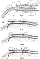
- Figure 7 To assist in the understanding of the operation of component 40, the device of Figures 6A to 6C is illustrated in Figure 7 without its outer sheath 46, as the device enters a renal artery. It should be borne in mind, however, that as the outer sheath 46 is omitted, Figure 7 does not show the ideal disposition of the radiating element. Were the outer sheath included, the radiating element would be better centred in the artery due to the action of the splines 52 (as shown in Figures 5B and 5B ), rather than being pressed against the arterial wall.
- FIG. 9 shows a device 80 in accordance with a further embodiment of the invention.
- Device 80 is the same as device 60 of Figures 3 and 5A to 5C , except that device 80 also includes a support component 54.
- the support component 54 is the same as support component 40, except that rather than extending to the end of the radiator 24, the distal end 41 of the support component 54 ends about midway along the radiating element 34. This provides a stepped thickness along the length of the radiator 24 that results the radiator 24 being more flexible at its distal end than at the distal end 41 of the support component 54. In other embodiments, there may be multiple steps in thickness along the length of the radiator 24 and/or the cover 54 may have a tapering profile. The tapering of the support component 54 at the junction 38 and the stepped thickness along the radiator 24 each contribute to providing the radiator 24 with a greater flexibility at its distal end 41 than at its proximal end.
- the radiator 24 is better able to track the angioplasty wire and there may be improved centering of the radiating element 34.
- a stiffer radiator may bias the radiating element 34 into one side of the vessel wall and overpower the soft centering splines 52.
- Figure 9 also illustrates further details in relation to the monorail segment 44.
- the monorail segment is in this embodiment attached to or is a continuation of the distal end 39 of the outer sheath 46, and is attached to the distal end 43 of the radiator 24. Having the radiator 24 stiffer towards its proximal end also provides the radiator 24 with enough structural integrity to push along the monorail without buckling.
- the outer sheath 46 is more flexible towards the distal end 45 of the catheter 10, 60, 80 where it will sit inside the renal artery, than more proximally. This is because from a location 49 about 50-100 mm from the radiator 24, the outer sheath 46 is thicker. This increased thickness is achieved by having a second layer 51 or a transition or join to another material with stiffer properties which allow for greater transmission of push to advance the system over the monorail.
- the thicker portion of outer sheath 46 extends back from the location 49 to fix to a haemostatic valve (not shown) at the proximal end (not shown) of catheter.
- the feed line 22 may be pulled with respect to the valve and outer sheath 46 to cause the splines 52 to protrude, or may be pushed to cause the splines 52 to retract.
- the valve includes an input which is used for introducing the saline solution to the catheter.
- the valve may include a Y connector, with one of the arms of the Y acting as the input.
- An example of such a part is part number 80303 manufactured by Qosina (Ronkonkoma, NY, USA).
- the saline solution will flow from the input site, along the space between the coaxial cable (feed line 22) and the outer sheath 46 and emerge from the slits in the outer sheath in the formation that produces the splines 52. Irrigation of the catheter during ablation prevents excessive temperature rise in the catheter shaft and prevents ingress of blood and thrombosis in the catheter.
- Having the catheter relatively more flexible towards its distal end (by having a relatively thinner outer sheath 46) enables the distal end 45 to follow the contour of the artery into which it is pushed, while the rest of the catheter is stiffer to enable the distal end 45 to be pushed into the artery.
- the optimal length of the radiating element depends on the near field environment of the radiating element and the frequency of operation of the microwave generator.
- the structural support component may necessitate appreciable changes in the resonant length of the radiator 24 and the radiating element 34 at which maximal radiation occurs at the proposed operating frequency. This is due to the structural support component changing the nearby environment around the radiator to which the microwave field couples.
- the microwave ablation device 10, 60 and 80 is designed to work at a frequency of 2.45GHz, and at this frequency, the length of a quarter wave radiating element would typically be about 4 mm. This is on the assumption that the radiator 24 is located in the blood pool. Because of the Teflon dielectric, which is on the radiating element to achieve electrical insulation, and because of the support component 54, the quarter wave length of the radiating element is increased to about 5 mm or more.
- a half wave radiating element may also be selected, i.e. a length of about 11 mm, and that full wave radiating element may alternatively be selected, with a length of about 22 mm.
- radiating element lengths beyond a full wavelength may cause unwanted results such as bilobal radiation from the tip and root of the element.
- a quarter wave radiating element radiates less energy into the near field than a half wave radiating element.
- the energy is bunched in an approximately 5mm zone, while the full wave radiating element radiates energy in a more spread pattern along the length of the radiating element.
- This pattern may have a length of about 15-19mm for a full wave radiator measuring 22mm in a matched environment, concentrated around the half-way point of the radiator.
- the power output is chosen to provide a high enough dose of microwave energy in order to ablate the perivascular tissues of the renal artery containing the renal nerves while being low enough to avoid injury to the arterial wall.
- a microwave energy dose delivery over about 3 minutes generally enables renal artery flow (along with saline irrigation) to keep the vessel luminal surface sufficiently cool to provide some sparing of injury to the renal artery wall under normal physiological conditions.
- an irrigation liquid in the form of a saline irrigant/solution is used as a flow between the outer device sheath 46 and the feed line 22 and in some instances the insulated radiating element 24.
- the saline solution is fed, in one example, at a rate of about 20 mL/minute along part of the device inserted into the body.
- the aims of this feed are to prevent a clot forming in the device bore, and also to provide cooling for the feed line 22.
- the power rating of the feed line 22 is 78W continuous, in air.
- the microwave ablation device 10, 60, 80 may be operated up to about 160W if liquid saline cooling is used.
- the renal artery may benefit from the flow as it is flushed with the saline solution.
- the vessel may spasm during the procedure, the guaranteed flow caused by the saline solution through the device keeps the artery walls cooler than due to reliance on blood flow alone.
- the device is introduced via a peripheral artery, such as the femoral artery, within a guiding sheath used to engage the ostium of the renal artery.
- a peripheral artery such as the femoral artery
- the device is introduced either directly or in an over the wire fashion into a segment of the renal artery.
- the device may be delivered to the renal artery 12 through the use of a conventional angioplasty wire.
- the locating formations 48.1 and 48.2 are deployed by moving the feed line relative to the outer device sheath until the locating formations 48.1 and 48.2 rest against the inner layers of the renal artery.
- the centering splines are capable of expanding to abut the walls of renal arteries of varying calibre, depending on how much relative movement occurs between the feed line and the outer device sheath. Angiographic estimation of renal artery calibre is made prior to spline deployment and graduated deployment of the splines is undertaken to centre device without causing arterial injury.
- the microwave generator is then activated for a period of approximately 3 minutes during which microwaves radiate from the radiating element. Due to the radiating element being insulated, and as mentioned above, alternating current cannot flow from the element into the surrounding biological environment and ohmic energy losses through current flow are thereby curtailed. Due to the flow of the saline solution within the device, and the continued flow of blood in the artery, the area immediately adjacent the radiator, including the inner and middle layers of the renal artery is sufficiently cooled for ablation thereof not to occur. However, due to there being no cooling of the deeper regions, substantial heating will occur in these regions, resulting in ablation. For example, in both Figures 1 and 4 , ablated areas are shown by reference numeral 64.
- microwave energy does not require catheter contact
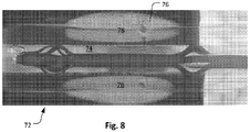
- FIG. 8 A prototype of the microwave ablation device 70 is shown in Figure 8 positioned in our longitudinal model 72 of a renal artery. This consisted of a tunnel (i.e. lumen) 74 in a microwave gel phantom material filled with 0.9% saline solution at 37°C flowing at a rate of 0.5L/min, which is the usual flow within the human renal artery. Within the phantom material is embedded a thermo-chromic liquid crystal sheet 76 which changes colour with temperatures between 50°C and 78°C, permitting assessment of the thermal lesion by photography and in-house built software for colour-temperature conversion. The feedline consisted of a 137cm long 50 ⁇ coaxial cable.
- the microwave ablation device 70 was introduced into the lumen 74 of the model 72 of the renal artery and an ablation at 2.45GHz, with 140W power for 180 seconds was performed to yield the final lesion shown by reference numeral 78.
- the elongate shape of the lesion is a visual indication of the elongate shape of the radiating pattern. 53°C is the commonly accepted approximate temperature beyond which cell death occurs and the thermo-chromic liquid crystal sheet displays this temperature band as the transition between red and green colours. It can be observed that the microwave ablation spares the first 1-2mm and extends to about 5-6mm deep to the surface of the modelled renal artery lumen. This is sufficient to yield thermal injury to the majority of renal nerves, the bulk of which exist 1-6mm from the vessel lumen while sparing the vessel intima and media which is within the first approximately 0.5mm.
- An exemplary method by which the catheter 10, 60, 80 of the present invention may be used for renal artery denervation involves the following steps:
- the microwave ablation device of the present invention is configured, in use, to allow for effective heating patterns that allow a single energy application, the heating pattern being spread across much of the length of the radiating element. Further, the heating pattern is more spread out (less circular / more elongate) than were the radiating element balanced and/or electromagnetically interrupted from the feedline by a choke and/or ground plane.
- the device is also configured to allow sufficient cooling of the feedline to enable high power to be used while renal artery flow and irrigant flow ensure protection of the inner layers of the artery from thermal injury, while denervation still occurs.
Claims (15)
- Dispositif d'ablation par micro-ondes (10) comprenant une ligne d'alimentation (22), un émetteur de micro-ondes (24) et une gaine externe de dispositif (46) dans laquelle est contenue au moins une partie de la ligne d'alimentation (22), la gaine (46), lors de son utilisation, permettant à un liquide d'irrigation de s'écouler à travers elle, la ligne d'alimentation présentant une jonction (38) avec l'émetteur (24) et un blindage conducteur externe (28) se terminant au niveau de la jonction et isolé au niveau de celle-ci (38), la ligne d'alimentation (22) présentant un noyau conducteur (32) qui s'étend jusqu'à l'émetteur (24), le noyau conducteur (32) formant un élément rayonnant (34) isolé électriquement de son environnement, l'émetteur (24) n'étant pas adapté à l'impédance de la ligne d'alimentation (22) et n'étant pas équilibré au niveau d'une extrémité distale.
- Dispositif d'ablation par micro-ondes (10) selon la revendication 1 dans lequel la gaine (46) contient l'émetteur de micro-ondes (24) et au moins une partie de la ligne d'alimentation (22).
- Dispositif d'ablation par micro-ondes (10) selon la revendication 1 ou la revendication 2 dans lequel la gaine (46) comporte une ou plusieurs formations de positionnement (48) configurées pour centrer et positionner le dispositif (10) lors de l'utilisation dans un vaisseau (12).
- Dispositif d'ablation par micro-ondes (10) selon l'une quelconque des revendications 1 à 3 dans lequel l'émetteur (24) comporte une couche isolante (30) s'étendant par-dessus l'élément rayonnant (34) ou un couvercle isolant enfermant ce dernier.
- Dispositif d'ablation par micro-ondes (10) selon la revendication 1, le dispositif (10) étant configuré en outre pour connecter la gaine externe de dispositif (46) à la ligne d'alimentation (22) et/ou à l'élément rayonnant isolé (34) pour ainsi permettre un mouvement relatif de la gaine (46) par rapport à la ligne d'alimentation (22) lors de l'utilisation, dans lequel la gaine (46) comporte les une ou plusieurs formations de connexion (48) comprenant des sections de fentes (50) dans la gaine (46) pour former des cannelures (52) qui se déploient pour former des protubérances convexes qui sont configurées pour interagir avec des parois de vaisseau (14), facultativement dans lequel un fluide d'irrigation peut s'écouler hors de la gaine (46) à travers les fentes (50).
- Dispositif d'ablation par micro-ondes (10) selon l'une quelconque des revendications 1 à 5, le dispositif d'ablation par micro-ondes (10) étant entraîné par une source d'énergie de micro-ondes.
- Dispositif d'ablation par micro-ondes (10) selon la revendication 6 dans lequel la source d'énergie de micro-ondes est actionnée à 2,45 GHz.
- Dispositif d'ablation par micro-ondes (10) selon la revendication 7 dans lequel le blindage externe (28) de la ligne d'alimentation (22) n'est pas connecté électromagnétiquement à une bobine d'arrêt ou des éléments radiaux de plan de masse.
- Dispositif d'ablation par micro-ondes (10) selon la revendication 8 dans lequel la source d'énergie de micro-ondes présente une sortie de puissance entre 40 W et 80 W pour une ligne d'alimentation (22) d'approximativement 80 cm et entre 100 W et 160 W pour une longueur de ligne d'alimentation (22) d'approximativement 140 cm.
- Dispositif d'ablation par micro-ondes (10) selon l'une quelconque des revendications 1 à 9 dans lequel l'émetteur (24) présente un seul élément rayonnant (34).
- Dispositif d'ablation par micro-ondes (10) selon l'une quelconque des revendications 1 à 10, le dispositif étant non équilibré en ce que différentes charges se trouvent sur le blindage conducteur externe (28) et le noyau conducteur (32), respectivement.
- Dispositif d'ablation par micro-ondes (10) selon l'une quelconque des revendications 1 à 11 dans lequel l'élément rayonnant (34) n'est pas connecté à un embout ou une bobine.
- Dispositif d'ablation par micro-ondes (10) selon l'une quelconque des revendications précédentes dans lequel le blindage conducteur externe (28) est isolé électriquement, au moyen d'un ou plusieurs
d'un adhésif ou manchon isolant (30) qui couvre l'extrémité distale du blindage conducteur externe (28), au niveau de la jonction (38) ; et
de la gaine de dispositif externe (46) pour isoler le blindage conducteur externe (28) d'une surface externe du dispositif (10). - Dispositif d'ablation par micro-ondes (10) selon l'une quelconque des revendications précédentes dans lequel une extrémité distale comporte une ouverture permettant à un fluide d'irrigation de s'écouler hors du dispositif (10) et par-dessus l'émetteur (24).
- Dispositif d'ablation par micro-ondes (10) selon l'une ou l'autre des revendications 3 ou 5 dans lequel une ou plusieurs formations de positionnement (48) sont formées par des fentes (50) dans la gaine (46) qui forment des cannelures (52) qui se déploient pour former des protubérances convexes qui interagissent avec des parois de vaisseau (14), et dans lequel un fluide d'irrigation peut s'écouler hors de la gaine (46) à travers les fentes (50).
Applications Claiming Priority (2)
| Application Number | Priority Date | Filing Date | Title |
|---|---|---|---|
| AU2015902225A AU2015902225A0 (en) | 2015-06-12 | Microwave ablation device | |
| PCT/AU2016/050480 WO2016197206A1 (fr) | 2015-06-12 | 2016-06-10 | Dispositif d'ablation par micro-ondes |
Publications (3)
| Publication Number | Publication Date |
|---|---|
| EP3307384A1 EP3307384A1 (fr) | 2018-04-18 |
| EP3307384A4 EP3307384A4 (fr) | 2019-02-20 |
| EP3307384B1 true EP3307384B1 (fr) | 2020-08-05 |
Family
ID=57502802
Family Applications (1)
| Application Number | Title | Priority Date | Filing Date |
|---|---|---|---|
| EP16806449.1A Active EP3307384B1 (fr) | 2015-06-12 | 2016-06-10 | Dispositif d'ablation par micro-ondes |
Country Status (7)
| Country | Link |
|---|---|
| US (1) | US11039884B2 (fr) |
| EP (1) | EP3307384B1 (fr) |
| JP (1) | JP6913673B2 (fr) |
| CN (1) | CN107921274B (fr) |
| AU (1) | AU2016275576B2 (fr) |
| CA (1) | CA2988609C (fr) |
| WO (1) | WO2016197206A1 (fr) |
Families Citing this family (5)
| Publication number | Priority date | Publication date | Assignee | Title |
|---|---|---|---|---|
| TWI640291B (zh) * | 2016-12-16 | 2018-11-11 | 巽晨國際股份有限公司 | Electromagnetic wave treatment device and method of use thereof |
| EP3573561B1 (fr) | 2017-01-26 | 2023-05-31 | Broncus Medical Inc. | Système et procédé d'ablation par micro-ondes basés sur bronchoscopie |
| CA3104358A1 (fr) * | 2018-07-19 | 2020-01-23 | The University Of Sydney | Dispositif d'ablation formant lesion |
| CA3105886A1 (fr) | 2018-08-13 | 2020-02-20 | The University Of Sydney | Dispositif d'ablation de catheter avec surveillance d'impedance |
| JP7376519B2 (ja) | 2018-08-13 | 2023-11-08 | ザ・ユニバーシティ・オブ・シドニー | 温度監視付きカテーテルアブレーション装置 |
Family Cites Families (16)
| Publication number | Priority date | Publication date | Assignee | Title |
|---|---|---|---|---|
| GB250673A (en) * | 1925-01-16 | 1926-04-16 | George Ogilby Fox Lane | Improved construction of plug and socket connections for electrical purposes |
| JPH08187297A (ja) * | 1995-01-11 | 1996-07-23 | Olympus Optical Co Ltd | マイクロ波治療装置 |
| US6210367B1 (en) | 1995-09-06 | 2001-04-03 | Microwave Medical Systems, Inc. | Intracorporeal microwave warming method and apparatus |
| US6610083B2 (en) * | 1998-08-24 | 2003-08-26 | Radiant Medical, Inc. | Multiple lumen heat exchange catheters |
| US6645199B1 (en) * | 1999-11-22 | 2003-11-11 | Scimed Life Systems, Inc. | Loop structures for supporting diagnostic and therapeutic elements contact with body tissue and expandable push devices for use with same |
| US8945111B2 (en) * | 2008-01-23 | 2015-02-03 | Covidien Lp | Choked dielectric loaded tip dipole microwave antenna |
| US8059059B2 (en) * | 2008-05-29 | 2011-11-15 | Vivant Medical, Inc. | Slidable choke microwave antenna |
| CN102245119B (zh) * | 2008-10-21 | 2017-06-06 | 微立方有限责任公司 | 将能量应用于身体组织的方法及装置 |
| GB2472972A (en) * | 2009-07-20 | 2011-03-02 | Microoncology Ltd | A microwave antenna |
| US8382750B2 (en) * | 2009-10-28 | 2013-02-26 | Vivant Medical, Inc. | System and method for monitoring ablation size |
| AU2010319477A1 (en) | 2009-11-11 | 2012-05-24 | Holaira, Inc. | Systems, apparatuses, and methods for treating tissue and controlling stenosis |
| CN103096826B (zh) * | 2010-04-26 | 2016-07-20 | 美敦力阿迪安卢森堡有限公司 | 用于肾神经调节的导管设备、系统和方法 |
| US20120116486A1 (en) * | 2010-10-25 | 2012-05-10 | Medtronic Ardian Luxembourg S.A.R.L. | Microwave catheter apparatuses, systems, and methods for renal neuromodulation |
| EP2693969B1 (fr) * | 2011-04-08 | 2016-02-03 | Covidien LP | Dispositif à micro-ondes pour traitement des tissus |
| GB2503673A (en) | 2012-07-03 | 2014-01-08 | Creo Medical Ltd | Electrosurgical device with convex under surface |
| US10076384B2 (en) * | 2013-03-08 | 2018-09-18 | Symple Surgical, Inc. | Balloon catheter apparatus with microwave emitter |
-
2016
- 2016-06-10 CA CA2988609A patent/CA2988609C/fr active Active
- 2016-06-10 WO PCT/AU2016/050480 patent/WO2016197206A1/fr active Application Filing
- 2016-06-10 AU AU2016275576A patent/AU2016275576B2/en active Active
- 2016-06-10 US US15/580,615 patent/US11039884B2/en active Active
- 2016-06-10 CN CN201680034334.8A patent/CN107921274B/zh active Active
- 2016-06-10 EP EP16806449.1A patent/EP3307384B1/fr active Active
- 2016-06-10 JP JP2018516609A patent/JP6913673B2/ja active Active
Non-Patent Citations (1)
| Title |
|---|
| None * |
Also Published As
| Publication number | Publication date |
|---|---|
| EP3307384A1 (fr) | 2018-04-18 |
| JP6913673B2 (ja) | 2021-08-04 |
| WO2016197206A1 (fr) | 2016-12-15 |
| JP2018522692A (ja) | 2018-08-16 |
| CA2988609A1 (fr) | 2016-12-15 |
| US11039884B2 (en) | 2021-06-22 |
| CN107921274A (zh) | 2018-04-17 |
| AU2016275576A1 (en) | 2018-01-04 |
| CA2988609C (fr) | 2023-09-05 |
| EP3307384A4 (fr) | 2019-02-20 |
| CN107921274B (zh) | 2020-08-04 |
| AU2016275576B2 (en) | 2020-08-20 |
| US20180221089A1 (en) | 2018-08-09 |
Similar Documents
| Publication | Publication Date | Title |
|---|---|---|
| EP3307384B1 (fr) | Dispositif d'ablation par micro-ondes | |
| US6669692B1 (en) | Ablation catheter with cooled linear electrode | |
| EP2693970B1 (fr) | Cathéters micro-ondes souples pour lumières naturelles ou artificielles | |
| US5275597A (en) | Percutaneous transluminal catheter and transmitter therefor | |
| CN103442659A (zh) | 装备有形状记忆材料的消融导管 | |
| AU2015202149B2 (en) | Flexible microwave catheters for natural or artificial lumens | |
| JP2006314785A (ja) | 補強された高強度マイクロ波アンテナ | |
| JPH05245208A (ja) | アンテナ構成 | |
| EP3823548A1 (fr) | Dispositif d'ablation formant lésion | |
| CN112638301A (zh) | 具有阻抗监测的导管消融设备 | |
| CN112638304A (zh) | 具有温度监测的导管消融设备 | |
| US11672597B2 (en) | Medical device and treatment method | |
| Gu et al. | A conformal microwave antenna applicator for circumferential ablation |
Legal Events
| Date | Code | Title | Description |
|---|---|---|---|
| STAA | Information on the status of an ep patent application or granted ep patent |
Free format text: STATUS: THE INTERNATIONAL PUBLICATION HAS BEEN MADE |
|
| PUAI | Public reference made under article 153(3) epc to a published international application that has entered the european phase |
Free format text: ORIGINAL CODE: 0009012 |
|
| STAA | Information on the status of an ep patent application or granted ep patent |
Free format text: STATUS: REQUEST FOR EXAMINATION WAS MADE |
|
| 17P | Request for examination filed |
Effective date: 20171221 |
|
| AK | Designated contracting states |
Kind code of ref document: A1 Designated state(s): AL AT BE BG CH CY CZ DE DK EE ES FI FR GB GR HR HU IE IS IT LI LT LU LV MC MK MT NL NO PL PT RO RS SE SI SK SM TR |
|
| AX | Request for extension of the european patent |
Extension state: BA ME |
|
| DAV | Request for validation of the european patent (deleted) | ||
| DAX | Request for extension of the european patent (deleted) | ||
| A4 | Supplementary search report drawn up and despatched |
Effective date: 20190123 |
|
| RIC1 | Information provided on ipc code assigned before grant |
Ipc: A61N 5/02 20060101AFI20190117BHEP Ipc: A61B 18/18 20060101ALI20190117BHEP |
|
| GRAP | Despatch of communication of intention to grant a patent |
Free format text: ORIGINAL CODE: EPIDOSNIGR1 |
|
| STAA | Information on the status of an ep patent application or granted ep patent |
Free format text: STATUS: GRANT OF PATENT IS INTENDED |
|
| INTG | Intention to grant announced |
Effective date: 20200226 |
|
| GRAS | Grant fee paid |
Free format text: ORIGINAL CODE: EPIDOSNIGR3 |
|
| GRAA | (expected) grant |
Free format text: ORIGINAL CODE: 0009210 |
|
| STAA | Information on the status of an ep patent application or granted ep patent |
Free format text: STATUS: THE PATENT HAS BEEN GRANTED |
|
| AK | Designated contracting states |
Kind code of ref document: B1 Designated state(s): AL AT BE BG CH CY CZ DE DK EE ES FI FR GB GR HR HU IE IS IT LI LT LU LV MC MK MT NL NO PL PT RO RS SE SI SK SM TR |
|
| REG | Reference to a national code |
Ref country code: GB Ref legal event code: FG4D |
|
| REG | Reference to a national code |
Ref country code: CH Ref legal event code: EP |
|
| REG | Reference to a national code |
Ref country code: AT Ref legal event code: REF Ref document number: 1297863 Country of ref document: AT Kind code of ref document: T Effective date: 20200815 |
|
| REG | Reference to a national code |
Ref country code: IE Ref legal event code: FG4D |
|
| REG | Reference to a national code |
Ref country code: DE Ref legal event code: R096 Ref document number: 602016041499 Country of ref document: DE |
|
| REG | Reference to a national code |
Ref country code: LT Ref legal event code: MG4D |
|
| REG | Reference to a national code |
Ref country code: NL Ref legal event code: MP Effective date: 20200805 |
|
| REG | Reference to a national code |
Ref country code: AT Ref legal event code: MK05 Ref document number: 1297863 Country of ref document: AT Kind code of ref document: T Effective date: 20200805 |
|
| PG25 | Lapsed in a contracting state [announced via postgrant information from national office to epo] |
Ref country code: PT Free format text: LAPSE BECAUSE OF FAILURE TO SUBMIT A TRANSLATION OF THE DESCRIPTION OR TO PAY THE FEE WITHIN THE PRESCRIBED TIME-LIMIT Effective date: 20201207 Ref country code: SE Free format text: LAPSE BECAUSE OF FAILURE TO SUBMIT A TRANSLATION OF THE DESCRIPTION OR TO PAY THE FEE WITHIN THE PRESCRIBED TIME-LIMIT Effective date: 20200805 Ref country code: AT Free format text: LAPSE BECAUSE OF FAILURE TO SUBMIT A TRANSLATION OF THE DESCRIPTION OR TO PAY THE FEE WITHIN THE PRESCRIBED TIME-LIMIT Effective date: 20200805 Ref country code: NO Free format text: LAPSE BECAUSE OF FAILURE TO SUBMIT A TRANSLATION OF THE DESCRIPTION OR TO PAY THE FEE WITHIN THE PRESCRIBED TIME-LIMIT Effective date: 20201105 Ref country code: GR Free format text: LAPSE BECAUSE OF FAILURE TO SUBMIT A TRANSLATION OF THE DESCRIPTION OR TO PAY THE FEE WITHIN THE PRESCRIBED TIME-LIMIT Effective date: 20201106 Ref country code: FI Free format text: LAPSE BECAUSE OF FAILURE TO SUBMIT A TRANSLATION OF THE DESCRIPTION OR TO PAY THE FEE WITHIN THE PRESCRIBED TIME-LIMIT Effective date: 20200805 Ref country code: BG Free format text: LAPSE BECAUSE OF FAILURE TO SUBMIT A TRANSLATION OF THE DESCRIPTION OR TO PAY THE FEE WITHIN THE PRESCRIBED TIME-LIMIT Effective date: 20201105 Ref country code: HR Free format text: LAPSE BECAUSE OF FAILURE TO SUBMIT A TRANSLATION OF THE DESCRIPTION OR TO PAY THE FEE WITHIN THE PRESCRIBED TIME-LIMIT Effective date: 20200805 Ref country code: LT Free format text: LAPSE BECAUSE OF FAILURE TO SUBMIT A TRANSLATION OF THE DESCRIPTION OR TO PAY THE FEE WITHIN THE PRESCRIBED TIME-LIMIT Effective date: 20200805 Ref country code: ES Free format text: LAPSE BECAUSE OF FAILURE TO SUBMIT A TRANSLATION OF THE DESCRIPTION OR TO PAY THE FEE WITHIN THE PRESCRIBED TIME-LIMIT Effective date: 20200805 |
|
| PG25 | Lapsed in a contracting state [announced via postgrant information from national office to epo] |
Ref country code: LV Free format text: LAPSE BECAUSE OF FAILURE TO SUBMIT A TRANSLATION OF THE DESCRIPTION OR TO PAY THE FEE WITHIN THE PRESCRIBED TIME-LIMIT Effective date: 20200805 Ref country code: PL Free format text: LAPSE BECAUSE OF FAILURE TO SUBMIT A TRANSLATION OF THE DESCRIPTION OR TO PAY THE FEE WITHIN THE PRESCRIBED TIME-LIMIT Effective date: 20200805 Ref country code: RS Free format text: LAPSE BECAUSE OF FAILURE TO SUBMIT A TRANSLATION OF THE DESCRIPTION OR TO PAY THE FEE WITHIN THE PRESCRIBED TIME-LIMIT Effective date: 20200805 Ref country code: NL Free format text: LAPSE BECAUSE OF FAILURE TO SUBMIT A TRANSLATION OF THE DESCRIPTION OR TO PAY THE FEE WITHIN THE PRESCRIBED TIME-LIMIT Effective date: 20200805 Ref country code: IS Free format text: LAPSE BECAUSE OF FAILURE TO SUBMIT A TRANSLATION OF THE DESCRIPTION OR TO PAY THE FEE WITHIN THE PRESCRIBED TIME-LIMIT Effective date: 20201205 |
|
| PG25 | Lapsed in a contracting state [announced via postgrant information from national office to epo] |
Ref country code: SM Free format text: LAPSE BECAUSE OF FAILURE TO SUBMIT A TRANSLATION OF THE DESCRIPTION OR TO PAY THE FEE WITHIN THE PRESCRIBED TIME-LIMIT Effective date: 20200805 Ref country code: EE Free format text: LAPSE BECAUSE OF FAILURE TO SUBMIT A TRANSLATION OF THE DESCRIPTION OR TO PAY THE FEE WITHIN THE PRESCRIBED TIME-LIMIT Effective date: 20200805 Ref country code: DK Free format text: LAPSE BECAUSE OF FAILURE TO SUBMIT A TRANSLATION OF THE DESCRIPTION OR TO PAY THE FEE WITHIN THE PRESCRIBED TIME-LIMIT Effective date: 20200805 Ref country code: CZ Free format text: LAPSE BECAUSE OF FAILURE TO SUBMIT A TRANSLATION OF THE DESCRIPTION OR TO PAY THE FEE WITHIN THE PRESCRIBED TIME-LIMIT Effective date: 20200805 Ref country code: RO Free format text: LAPSE BECAUSE OF FAILURE TO SUBMIT A TRANSLATION OF THE DESCRIPTION OR TO PAY THE FEE WITHIN THE PRESCRIBED TIME-LIMIT Effective date: 20200805 |
|
| REG | Reference to a national code |
Ref country code: DE Ref legal event code: R097 Ref document number: 602016041499 Country of ref document: DE |
|
| PG25 | Lapsed in a contracting state [announced via postgrant information from national office to epo] |
Ref country code: AL Free format text: LAPSE BECAUSE OF FAILURE TO SUBMIT A TRANSLATION OF THE DESCRIPTION OR TO PAY THE FEE WITHIN THE PRESCRIBED TIME-LIMIT Effective date: 20200805 |
|
| PLBE | No opposition filed within time limit |
Free format text: ORIGINAL CODE: 0009261 |
|
| STAA | Information on the status of an ep patent application or granted ep patent |
Free format text: STATUS: NO OPPOSITION FILED WITHIN TIME LIMIT |
|
| PG25 | Lapsed in a contracting state [announced via postgrant information from national office to epo] |
Ref country code: SK Free format text: LAPSE BECAUSE OF FAILURE TO SUBMIT A TRANSLATION OF THE DESCRIPTION OR TO PAY THE FEE WITHIN THE PRESCRIBED TIME-LIMIT Effective date: 20200805 |
|
| 26N | No opposition filed |
Effective date: 20210507 |
|
| PG25 | Lapsed in a contracting state [announced via postgrant information from national office to epo] |
Ref country code: IT Free format text: LAPSE BECAUSE OF FAILURE TO SUBMIT A TRANSLATION OF THE DESCRIPTION OR TO PAY THE FEE WITHIN THE PRESCRIBED TIME-LIMIT Effective date: 20200805 |
|
| PG25 | Lapsed in a contracting state [announced via postgrant information from national office to epo] |
Ref country code: SI Free format text: LAPSE BECAUSE OF FAILURE TO SUBMIT A TRANSLATION OF THE DESCRIPTION OR TO PAY THE FEE WITHIN THE PRESCRIBED TIME-LIMIT Effective date: 20200805 |
|
| PG25 | Lapsed in a contracting state [announced via postgrant information from national office to epo] |
Ref country code: MC Free format text: LAPSE BECAUSE OF FAILURE TO SUBMIT A TRANSLATION OF THE DESCRIPTION OR TO PAY THE FEE WITHIN THE PRESCRIBED TIME-LIMIT Effective date: 20200805 |
|
| REG | Reference to a national code |
Ref country code: CH Ref legal event code: PL |
|
| REG | Reference to a national code |
Ref country code: BE Ref legal event code: MM Effective date: 20210630 |
|
| PG25 | Lapsed in a contracting state [announced via postgrant information from national office to epo] |
Ref country code: LU Free format text: LAPSE BECAUSE OF NON-PAYMENT OF DUE FEES Effective date: 20210610 |
|
| PG25 | Lapsed in a contracting state [announced via postgrant information from national office to epo] |
Ref country code: LI Free format text: LAPSE BECAUSE OF NON-PAYMENT OF DUE FEES Effective date: 20210630 Ref country code: IE Free format text: LAPSE BECAUSE OF NON-PAYMENT OF DUE FEES Effective date: 20210610 Ref country code: CH Free format text: LAPSE BECAUSE OF NON-PAYMENT OF DUE FEES Effective date: 20210630 |
|
| PG25 | Lapsed in a contracting state [announced via postgrant information from national office to epo] |
Ref country code: BE Free format text: LAPSE BECAUSE OF NON-PAYMENT OF DUE FEES Effective date: 20210630 |
|
| PG25 | Lapsed in a contracting state [announced via postgrant information from national office to epo] |
Ref country code: CY Free format text: LAPSE BECAUSE OF FAILURE TO SUBMIT A TRANSLATION OF THE DESCRIPTION OR TO PAY THE FEE WITHIN THE PRESCRIBED TIME-LIMIT Effective date: 20200805 |
|
| P01 | Opt-out of the competence of the unified patent court (upc) registered |
Effective date: 20230619 |
|
| PG25 | Lapsed in a contracting state [announced via postgrant information from national office to epo] |
Ref country code: HU Free format text: LAPSE BECAUSE OF FAILURE TO SUBMIT A TRANSLATION OF THE DESCRIPTION OR TO PAY THE FEE WITHIN THE PRESCRIBED TIME-LIMIT; INVALID AB INITIO Effective date: 20160610 |
|
| PGFP | Annual fee paid to national office [announced via postgrant information from national office to epo] |
Ref country code: FR Payment date: 20230628 Year of fee payment: 8 Ref country code: DE Payment date: 20230620 Year of fee payment: 8 |
|
| PGFP | Annual fee paid to national office [announced via postgrant information from national office to epo] |
Ref country code: GB Payment date: 20230622 Year of fee payment: 8 |
|
| PG25 | Lapsed in a contracting state [announced via postgrant information from national office to epo] |
Ref country code: MK Free format text: LAPSE BECAUSE OF FAILURE TO SUBMIT A TRANSLATION OF THE DESCRIPTION OR TO PAY THE FEE WITHIN THE PRESCRIBED TIME-LIMIT Effective date: 20200805 |