EP3307356B1 - Improved components of a fluid transfer apparatus - Google Patents
Improved components of a fluid transfer apparatus Download PDFInfo
- Publication number
- EP3307356B1 EP3307356B1 EP16807024.1A EP16807024A EP3307356B1 EP 3307356 B1 EP3307356 B1 EP 3307356B1 EP 16807024 A EP16807024 A EP 16807024A EP 3307356 B1 EP3307356 B1 EP 3307356B1
- Authority
- EP
- European Patent Office
- Prior art keywords
- component
- arms
- connector
- septum
- septum holder
- Prior art date
- Legal status (The legal status is an assumption and is not a legal conclusion. Google has not performed a legal analysis and makes no representation as to the accuracy of the status listed.)
- Active
Links
- 238000012546 transfer Methods 0.000 title claims description 78
- 239000012530 fluid Substances 0.000 title claims description 66
- 238000000034 method Methods 0.000 claims description 24
- 230000008569 process Effects 0.000 claims description 12
- 238000002604 ultrasonography Methods 0.000 claims description 5
- 239000007788 liquid Substances 0.000 description 71
- 229940079593 drug Drugs 0.000 description 54
- 239000003814 drug Substances 0.000 description 54
- 239000012528 membrane Substances 0.000 description 53
- 238000001990 intravenous administration Methods 0.000 description 18
- 231100001261 hazardous Toxicity 0.000 description 15
- 238000007789 sealing Methods 0.000 description 14
- 230000006870 function Effects 0.000 description 7
- 239000000243 solution Substances 0.000 description 7
- 230000004888 barrier function Effects 0.000 description 6
- 230000008901 benefit Effects 0.000 description 6
- 238000004891 communication Methods 0.000 description 6
- 238000013461 design Methods 0.000 description 6
- 238000003825 pressing Methods 0.000 description 6
- 230000006872 improvement Effects 0.000 description 5
- 230000005012 migration Effects 0.000 description 5
- 238000013508 migration Methods 0.000 description 5
- 239000012858 resilient material Substances 0.000 description 5
- 238000004519 manufacturing process Methods 0.000 description 4
- 238000003466 welding Methods 0.000 description 4
- 238000001802 infusion Methods 0.000 description 3
- 238000003780 insertion Methods 0.000 description 3
- 230000037431 insertion Effects 0.000 description 3
- 238000002955 isolation Methods 0.000 description 3
- 239000000463 material Substances 0.000 description 3
- 230000000717 retained effect Effects 0.000 description 3
- 239000007787 solid Substances 0.000 description 3
- CMSMOCZEIVJLDB-UHFFFAOYSA-N Cyclophosphamide Chemical compound ClCCN(CCCl)P1(=O)NCCCO1 CMSMOCZEIVJLDB-UHFFFAOYSA-N 0.000 description 2
- 238000004026 adhesive bonding Methods 0.000 description 2
- 238000010276 construction Methods 0.000 description 2
- 230000008878 coupling Effects 0.000 description 2
- 238000010168 coupling process Methods 0.000 description 2
- 238000005859 coupling reaction Methods 0.000 description 2
- 238000006073 displacement reaction Methods 0.000 description 2
- 230000036512 infertility Effects 0.000 description 2
- 238000002347 injection Methods 0.000 description 2
- 239000007924 injection Substances 0.000 description 2
- 230000007257 malfunction Effects 0.000 description 2
- 238000005259 measurement Methods 0.000 description 2
- 230000007246 mechanism Effects 0.000 description 2
- 238000012986 modification Methods 0.000 description 2
- 230000004048 modification Effects 0.000 description 2
- 230000002265 prevention Effects 0.000 description 2
- 238000005070 sampling Methods 0.000 description 2
- VVIAGPKUTFNRDU-UHFFFAOYSA-N 6S-folinic acid Natural products C1NC=2NC(N)=NC(=O)C=2N(C=O)C1CNC1=CC=C(C(=O)NC(CCC(O)=O)C(O)=O)C=C1 VVIAGPKUTFNRDU-UHFFFAOYSA-N 0.000 description 1
- 206010000234 Abortion spontaneous Diseases 0.000 description 1
- GHASVSINZRGABV-UHFFFAOYSA-N Fluorouracil Chemical compound FC1=CNC(=O)NC1=O GHASVSINZRGABV-UHFFFAOYSA-N 0.000 description 1
- 206010067125 Liver injury Diseases 0.000 description 1
- 229930012538 Paclitaxel Natural products 0.000 description 1
- 208000005107 Premature Birth Diseases 0.000 description 1
- 206010036590 Premature baby Diseases 0.000 description 1
- 208000000453 Skin Neoplasms Diseases 0.000 description 1
- FAPWRFPIFSIZLT-UHFFFAOYSA-M Sodium chloride Chemical compound [Na+].[Cl-] FAPWRFPIFSIZLT-UHFFFAOYSA-M 0.000 description 1
- 230000009471 action Effects 0.000 description 1
- 230000006978 adaptation Effects 0.000 description 1
- 239000003242 anti bacterial agent Substances 0.000 description 1
- 229940088710 antibiotic agent Drugs 0.000 description 1
- 239000003443 antiviral agent Substances 0.000 description 1
- 229940044683 chemotherapy drug Drugs 0.000 description 1
- -1 chemotherapy drugs Substances 0.000 description 1
- 239000000356 contaminant Substances 0.000 description 1
- 238000011109 contamination Methods 0.000 description 1
- 229960004397 cyclophosphamide Drugs 0.000 description 1
- 231100000599 cytotoxic agent Toxicity 0.000 description 1
- 239000002619 cytotoxin Substances 0.000 description 1
- 230000006378 damage Effects 0.000 description 1
- 230000001419 dependent effect Effects 0.000 description 1
- 239000013536 elastomeric material Substances 0.000 description 1
- 238000005516 engineering process Methods 0.000 description 1
- VJJPUSNTGOMMGY-MRVIYFEKSA-N etoposide Chemical compound COC1=C(O)C(OC)=CC([C@@H]2C3=CC=4OCOC=4C=C3[C@@H](O[C@H]3[C@@H]([C@@H](O)[C@@H]4O[C@H](C)OC[C@H]4O3)O)[C@@H]3[C@@H]2C(OC3)=O)=C1 VJJPUSNTGOMMGY-MRVIYFEKSA-N 0.000 description 1
- 229960005420 etoposide Drugs 0.000 description 1
- 229960002949 fluorouracil Drugs 0.000 description 1
- VVIAGPKUTFNRDU-ABLWVSNPSA-N folinic acid Chemical compound C1NC=2NC(N)=NC(=O)C=2N(C=O)C1CNC1=CC=C(C(=O)N[C@@H](CCC(O)=O)C(O)=O)C=C1 VVIAGPKUTFNRDU-ABLWVSNPSA-N 0.000 description 1
- 235000008191 folinic acid Nutrition 0.000 description 1
- 239000011672 folinic acid Substances 0.000 description 1
- 210000002683 foot Anatomy 0.000 description 1
- 239000007789 gas Substances 0.000 description 1
- 239000003292 glue Substances 0.000 description 1
- 239000000383 hazardous chemical Substances 0.000 description 1
- 231100000206 health hazard Toxicity 0.000 description 1
- 230000005802 health problem Effects 0.000 description 1
- 231100000234 hepatic damage Toxicity 0.000 description 1
- 229940022353 herceptin Drugs 0.000 description 1
- 230000002209 hydrophobic effect Effects 0.000 description 1
- 239000011261 inert gas Substances 0.000 description 1
- 229960001691 leucovorin Drugs 0.000 description 1
- 208000032839 leukemia Diseases 0.000 description 1
- 230000008818 liver damage Effects 0.000 description 1
- 230000036244 malformation Effects 0.000 description 1
- 239000012569 microbial contaminant Substances 0.000 description 1
- 230000000813 microbial effect Effects 0.000 description 1
- 244000005700 microbiome Species 0.000 description 1
- 208000015994 miscarriage Diseases 0.000 description 1
- 238000006386 neutralization reaction Methods 0.000 description 1
- 229960001592 paclitaxel Drugs 0.000 description 1
- 238000007911 parenteral administration Methods 0.000 description 1
- 230000037361 pathway Effects 0.000 description 1
- 230000000149 penetrating effect Effects 0.000 description 1
- 230000000144 pharmacologic effect Effects 0.000 description 1
- 239000000843 powder Substances 0.000 description 1
- 238000002360 preparation method Methods 0.000 description 1
- 230000001681 protective effect Effects 0.000 description 1
- 229940121896 radiopharmaceutical Drugs 0.000 description 1
- 239000012217 radiopharmaceutical Substances 0.000 description 1
- 230000002799 radiopharmaceutical effect Effects 0.000 description 1
- 229910052710 silicon Inorganic materials 0.000 description 1
- 239000010703 silicon Substances 0.000 description 1
- 201000000849 skin cancer Diseases 0.000 description 1
- 239000011343 solid material Substances 0.000 description 1
- 208000000995 spontaneous abortion Diseases 0.000 description 1
- RCINICONZNJXQF-MZXODVADSA-N taxol Chemical compound O([C@@H]1[C@@]2(C[C@@H](C(C)=C(C2(C)C)[C@H](C([C@]2(C)[C@@H](O)C[C@H]3OC[C@]3([C@H]21)OC(C)=O)=O)OC(=O)C)OC(=O)[C@H](O)[C@@H](NC(=O)C=1C=CC=CC=1)C=1C=CC=CC=1)O)C(=O)C1=CC=CC=C1 RCINICONZNJXQF-MZXODVADSA-N 0.000 description 1
- 210000003371 toe Anatomy 0.000 description 1
- 231100000331 toxic Toxicity 0.000 description 1
- 230000002588 toxic effect Effects 0.000 description 1
- 238000009423 ventilation Methods 0.000 description 1
Images


Classifications
-
- A—HUMAN NECESSITIES
- A61—MEDICAL OR VETERINARY SCIENCE; HYGIENE
- A61M—DEVICES FOR INTRODUCING MEDIA INTO, OR ONTO, THE BODY; DEVICES FOR TRANSDUCING BODY MEDIA OR FOR TAKING MEDIA FROM THE BODY; DEVICES FOR PRODUCING OR ENDING SLEEP OR STUPOR
- A61M5/00—Devices for bringing media into the body in a subcutaneous, intra-vascular or intramuscular way; Accessories therefor, e.g. filling or cleaning devices, arm-rests
- A61M5/178—Syringes
- A61M5/31—Details
- A61M5/3129—Syringe barrels
- A61M5/3135—Syringe barrels characterised by constructional features of the proximal end
-
- A—HUMAN NECESSITIES
- A61—MEDICAL OR VETERINARY SCIENCE; HYGIENE
- A61J—CONTAINERS SPECIALLY ADAPTED FOR MEDICAL OR PHARMACEUTICAL PURPOSES; DEVICES OR METHODS SPECIALLY ADAPTED FOR BRINGING PHARMACEUTICAL PRODUCTS INTO PARTICULAR PHYSICAL OR ADMINISTERING FORMS; DEVICES FOR ADMINISTERING FOOD OR MEDICINES ORALLY; BABY COMFORTERS; DEVICES FOR RECEIVING SPITTLE
- A61J1/00—Containers specially adapted for medical or pharmaceutical purposes
- A61J1/05—Containers specially adapted for medical or pharmaceutical purposes for collecting, storing or administering blood, plasma or medical fluids ; Infusion or perfusion containers
- A61J1/10—Bag-type containers
-
- A—HUMAN NECESSITIES
- A61—MEDICAL OR VETERINARY SCIENCE; HYGIENE
- A61J—CONTAINERS SPECIALLY ADAPTED FOR MEDICAL OR PHARMACEUTICAL PURPOSES; DEVICES OR METHODS SPECIALLY ADAPTED FOR BRINGING PHARMACEUTICAL PRODUCTS INTO PARTICULAR PHYSICAL OR ADMINISTERING FORMS; DEVICES FOR ADMINISTERING FOOD OR MEDICINES ORALLY; BABY COMFORTERS; DEVICES FOR RECEIVING SPITTLE
- A61J1/00—Containers specially adapted for medical or pharmaceutical purposes
- A61J1/14—Details; Accessories therefor
- A61J1/1406—Septums, pierceable membranes
-
- A—HUMAN NECESSITIES
- A61—MEDICAL OR VETERINARY SCIENCE; HYGIENE
- A61J—CONTAINERS SPECIALLY ADAPTED FOR MEDICAL OR PHARMACEUTICAL PURPOSES; DEVICES OR METHODS SPECIALLY ADAPTED FOR BRINGING PHARMACEUTICAL PRODUCTS INTO PARTICULAR PHYSICAL OR ADMINISTERING FORMS; DEVICES FOR ADMINISTERING FOOD OR MEDICINES ORALLY; BABY COMFORTERS; DEVICES FOR RECEIVING SPITTLE
- A61J1/00—Containers specially adapted for medical or pharmaceutical purposes
- A61J1/14—Details; Accessories therefor
- A61J1/1475—Inlet or outlet ports
- A61J1/1481—Inlet or outlet ports with connection retaining means, e.g. thread or snap-fit
-
- A—HUMAN NECESSITIES
- A61—MEDICAL OR VETERINARY SCIENCE; HYGIENE
- A61J—CONTAINERS SPECIALLY ADAPTED FOR MEDICAL OR PHARMACEUTICAL PURPOSES; DEVICES OR METHODS SPECIALLY ADAPTED FOR BRINGING PHARMACEUTICAL PRODUCTS INTO PARTICULAR PHYSICAL OR ADMINISTERING FORMS; DEVICES FOR ADMINISTERING FOOD OR MEDICINES ORALLY; BABY COMFORTERS; DEVICES FOR RECEIVING SPITTLE
- A61J1/00—Containers specially adapted for medical or pharmaceutical purposes
- A61J1/14—Details; Accessories therefor
- A61J1/20—Arrangements for transferring or mixing fluids, e.g. from vial to syringe
- A61J1/2003—Accessories used in combination with means for transfer or mixing of fluids, e.g. for activating fluid flow, separating fluids, filtering fluid or venting
- A61J1/2006—Piercing means
- A61J1/201—Piercing means having one piercing end
-
- A—HUMAN NECESSITIES
- A61—MEDICAL OR VETERINARY SCIENCE; HYGIENE
- A61J—CONTAINERS SPECIALLY ADAPTED FOR MEDICAL OR PHARMACEUTICAL PURPOSES; DEVICES OR METHODS SPECIALLY ADAPTED FOR BRINGING PHARMACEUTICAL PRODUCTS INTO PARTICULAR PHYSICAL OR ADMINISTERING FORMS; DEVICES FOR ADMINISTERING FOOD OR MEDICINES ORALLY; BABY COMFORTERS; DEVICES FOR RECEIVING SPITTLE
- A61J1/00—Containers specially adapted for medical or pharmaceutical purposes
- A61J1/14—Details; Accessories therefor
- A61J1/20—Arrangements for transferring or mixing fluids, e.g. from vial to syringe
- A61J1/2003—Accessories used in combination with means for transfer or mixing of fluids, e.g. for activating fluid flow, separating fluids, filtering fluid or venting
- A61J1/2048—Connecting means
- A61J1/2055—Connecting means having gripping means
-
- A—HUMAN NECESSITIES
- A61—MEDICAL OR VETERINARY SCIENCE; HYGIENE
- A61J—CONTAINERS SPECIALLY ADAPTED FOR MEDICAL OR PHARMACEUTICAL PURPOSES; DEVICES OR METHODS SPECIALLY ADAPTED FOR BRINGING PHARMACEUTICAL PRODUCTS INTO PARTICULAR PHYSICAL OR ADMINISTERING FORMS; DEVICES FOR ADMINISTERING FOOD OR MEDICINES ORALLY; BABY COMFORTERS; DEVICES FOR RECEIVING SPITTLE
- A61J1/00—Containers specially adapted for medical or pharmaceutical purposes
- A61J1/14—Details; Accessories therefor
- A61J1/20—Arrangements for transferring or mixing fluids, e.g. from vial to syringe
- A61J1/2003—Accessories used in combination with means for transfer or mixing of fluids, e.g. for activating fluid flow, separating fluids, filtering fluid or venting
- A61J1/2048—Connecting means
- A61J1/2065—Connecting means having aligning and guiding means
-
- A—HUMAN NECESSITIES
- A61—MEDICAL OR VETERINARY SCIENCE; HYGIENE
- A61J—CONTAINERS SPECIALLY ADAPTED FOR MEDICAL OR PHARMACEUTICAL PURPOSES; DEVICES OR METHODS SPECIALLY ADAPTED FOR BRINGING PHARMACEUTICAL PRODUCTS INTO PARTICULAR PHYSICAL OR ADMINISTERING FORMS; DEVICES FOR ADMINISTERING FOOD OR MEDICINES ORALLY; BABY COMFORTERS; DEVICES FOR RECEIVING SPITTLE
- A61J1/00—Containers specially adapted for medical or pharmaceutical purposes
- A61J1/14—Details; Accessories therefor
- A61J1/20—Arrangements for transferring or mixing fluids, e.g. from vial to syringe
- A61J1/2096—Combination of a vial and a syringe for transferring or mixing their contents
-
- A—HUMAN NECESSITIES
- A61—MEDICAL OR VETERINARY SCIENCE; HYGIENE
- A61M—DEVICES FOR INTRODUCING MEDIA INTO, OR ONTO, THE BODY; DEVICES FOR TRANSDUCING BODY MEDIA OR FOR TAKING MEDIA FROM THE BODY; DEVICES FOR PRODUCING OR ENDING SLEEP OR STUPOR
- A61M39/00—Tubes, tube connectors, tube couplings, valves, access sites or the like, specially adapted for medical use
- A61M39/10—Tube connectors; Tube couplings
-
- A—HUMAN NECESSITIES
- A61—MEDICAL OR VETERINARY SCIENCE; HYGIENE
- A61M—DEVICES FOR INTRODUCING MEDIA INTO, OR ONTO, THE BODY; DEVICES FOR TRANSDUCING BODY MEDIA OR FOR TAKING MEDIA FROM THE BODY; DEVICES FOR PRODUCING OR ENDING SLEEP OR STUPOR
- A61M5/00—Devices for bringing media into the body in a subcutaneous, intra-vascular or intramuscular way; Accessories therefor, e.g. filling or cleaning devices, arm-rests
- A61M5/14—Infusion devices, e.g. infusing by gravity; Blood infusion; Accessories therefor
- A61M5/1413—Modular systems comprising interconnecting elements
-
- A—HUMAN NECESSITIES
- A61—MEDICAL OR VETERINARY SCIENCE; HYGIENE
- A61M—DEVICES FOR INTRODUCING MEDIA INTO, OR ONTO, THE BODY; DEVICES FOR TRANSDUCING BODY MEDIA OR FOR TAKING MEDIA FROM THE BODY; DEVICES FOR PRODUCING OR ENDING SLEEP OR STUPOR
- A61M5/00—Devices for bringing media into the body in a subcutaneous, intra-vascular or intramuscular way; Accessories therefor, e.g. filling or cleaning devices, arm-rests
- A61M5/178—Syringes
- A61M5/31—Details
- A61M2005/3101—Leak prevention means for proximal end of syringes, i.e. syringe end opposite to needle mounting end
-
- A—HUMAN NECESSITIES
- A61—MEDICAL OR VETERINARY SCIENCE; HYGIENE
- A61M—DEVICES FOR INTRODUCING MEDIA INTO, OR ONTO, THE BODY; DEVICES FOR TRANSDUCING BODY MEDIA OR FOR TAKING MEDIA FROM THE BODY; DEVICES FOR PRODUCING OR ENDING SLEEP OR STUPOR
- A61M5/00—Devices for bringing media into the body in a subcutaneous, intra-vascular or intramuscular way; Accessories therefor, e.g. filling or cleaning devices, arm-rests
- A61M5/178—Syringes
- A61M5/31—Details
- A61M2005/3117—Means preventing contamination of the medicament compartment of a syringe
- A61M2005/3121—Means preventing contamination of the medicament compartment of a syringe via the proximal end of a syringe, i.e. syringe end opposite to needle cannula mounting end
-
- A—HUMAN NECESSITIES
- A61—MEDICAL OR VETERINARY SCIENCE; HYGIENE
- A61M—DEVICES FOR INTRODUCING MEDIA INTO, OR ONTO, THE BODY; DEVICES FOR TRANSDUCING BODY MEDIA OR FOR TAKING MEDIA FROM THE BODY; DEVICES FOR PRODUCING OR ENDING SLEEP OR STUPOR
- A61M39/00—Tubes, tube connectors, tube couplings, valves, access sites or the like, specially adapted for medical use
- A61M39/10—Tube connectors; Tube couplings
- A61M2039/1077—Adapters, e.g. couplings adapting a connector to one or several other connectors
Definitions
- the present invention relates to the field of fluid transfer apparatuses.
- the invention relates to apparatus for the contamination-free transfer of a hazardous drug from one container to another or to a patient. More particularly, the invention relates to improvements to syringes and to connectors and adapters that are used in fluid transfer apparatuses.
- a "hazardous drug” is any injectable material the contact with which, or with the vapors of which, may constitute a health hazard.
- cytotoxins include, inter alia, cytotoxins, antiviral drugs, chemotherapy drugs, antibiotics, and radiopharmaceuticals, such as herceptin, cisplatinum, fluorouracil, leucovorin, paclitaxel, etoposide, cyclophosphamide and neosar, or a combination thereof, in a liquid, solid, or gaseous state.
- radiopharmaceuticals such as herceptin, cisplatinum, fluorouracil, leucovorin, paclitaxel, etoposide, cyclophosphamide and neosar, or a combination thereof, in a liquid, solid, or gaseous state.
- Hazardous drugs in liquid or powder form are contained within vials, and are typically prepared in a separate room by pharmacists provided with protective clothing, a mouth mask, and a laminar flow safety cabinet.
- a syringe provided with a cannula, i.e. a hollow needle, is used for transferring the drug from a vial.
- the hazardous drug is added to a solution contained in a bag which is intended for parenteral administration, such as a saline solution intended for intravenous administration.
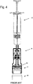
- FIG. 1 and Fig. 3a to 3b are schematic cross-sectional views of an apparatus 10 for transferring hazardous drugs without contaminating the surroundings, according to one embodiment of the invention described in US 8,196,614 .
- the main features of this apparatus that are relevant to the present invention will be described herein. Additional details can be found in the aforementioned patent.
- the proximal section of apparatus 10 is a syringe 12, which is adapted to draw or inject a desired volume of a hazardous drug from a fluid transfer component, e.g. a vial 16 or an intravenous (IV) bag in which it is contained and to subsequently transfer the drug to another fluid transfer component.
- a fluid transfer component e.g. a vial 16 or an intravenous (IV) bag in which it is contained and to subsequently transfer the drug to another fluid transfer component.
- IV intravenous
- Syringe 12 of apparatus 10 is comprised of a cylindrical body 18 having a tubular throat 20 that has a considerably smaller diameter than body 18, an annular rubber gasket or stopper assembly 22 fitted on the proximal end of cylindrical body 18, hollow piston rod 24 which sealingly passes through stopper 22, and proximal piston rod cap 26 by which a user can push and pull piston rod 24 up and down through stopper 22.
- a piston 28 made of an elastomeric material is securely attached to the distal end of piston rod 24.
- Cylindrical body 18 is made of a rigid material, e.g. plastic.
- Piston 28 which sealingly engages the inner wall of, and is displaceable with respect to, cylindrical body 18 defines two chambers of variable volume: a distal liquid chamber 30 between the distal face of piston 28 and connector section 14 and a proximal air chamber 32 between the proximal face of piston 28 and stopper 22.
- Connector section 14 is connected to the throat 20 of syringe 12 by means of a collar which proximally protrudes from the top of connector section 14 and surrounds throat 20. Note that embodiments of the apparatus do not necessarily have a throat 20. In these embodiments syringe 12 and connector section 14 are formed together as a single element at the time of manufacture, or permanently attached together, e.g. by means of glue or welding, or formed with a coupling means, such as threaded engagement or a Luer connector.
- the connector section 14 comprises a double membrane seal actuator which is moveable in a reciprocating manner from a normal, first configuration in which the needles are concealed when the double membrane seal actuator is disposed in a first, distal position and a second position in which the needles are exposed when the double membrane seal actuator is proximally displaced.
- Connector section 14 is adapted to be releasably coupled to another fluid transfer component, which can be any fluid container with a standard connector such as a drug vial, intravenous bag, or an intravenous line to produce a "fluid transfer assembly", through which a fluid is transferred from one fluid transfer component to another.
- Connector section 14 comprises a cylindrical, hollow outer body; a distal shoulder portion 19, which radially protrudes from the body and terminates at the distal end with an opening through which the proximal end of a fluid transfer component is inserted for coupling; a double membrane seal actuator 34, which is reciprocally displaceable within the interior of the body; and one or more resilient arms 35 serving as locking elements, which are connected at a proximal end thereof to an intermediate portion of a cylindrical actuator casing that contains double membrane seal actuator 34.
- Two hollow needles that function as air conduit 38 and liquid conduit 40 are fixedly retained in needle holder 36, which protrudes into the interior of connector section 14 from a central portion of the top of connector section 14.
- Conduits 38 and 40 distally extend from needle holder 36, piercing the upper membrane of actuator 34.
- the distal ends of conduits 38 and 40 have sharp pointed ends and apertures through which air and liquid can pass into and out of the interiors of the conduits respectively as required during a fluid transfer operation.
- the proximal end of air conduit 38 extends within the interior of proximal air chamber 32 in syringe 12.
- air conduit 38 passes through piston 28 and extends inside of hollow piston rod 24. Air flowing through conduit 38 enters/exits the interior of piston rod 24 and exits/enters to air chamber 32 through an aperture formed at the distal end of piston rod 24 just above piston 28.
- the proximal end of liquid conduit 40 terminates at the top of or slightly proximally from the top of needle holder 36, so that the liquid conduit will be in fluid communication with the distal liquid chamber 30 via the interior of throat 20 of syringe 12.
- Double membrane seal actuator 34 comprises a cylindrical casing that holds a proximal disc shaped membrane 34a having a rectangular cross-section and a two level distal membrane 34b having a T-shaped cross-section with disc shaped proximal portion and a disc shaped distal portion disposed radially inwards with respect to the proximal portion.
- the distal portion of the distal membrane 34b protrudes distally from actuator 34.
- Two or more equal length resilient elongated arms 35 are attached to the distal end of the casing of actuator 34. The arms terminate with distal enlarged elements.
- conduits 38 and 40 When actuator 34 is in a first position, the pointed ends of conduits 38 and 40 are retained between the proximal and distal membranes, isolating the ends of conduits 30 and 40 from the surroundings, thereby preventing contamination of the interior of syringe 12 and leakage of a harmful drug contained within its interior to the surroundings.
- Vial adapter 15 is an intermediate connection that is used to connect connector section 14 to a drug vial 16 or any other component having a suitably shaped and dimensioned port.
- Vial adapter 15 comprises a disk shaped central piece to which a plurality of circumferential segments, formed with a convex lip on the inner face thereof for facilitating securement to a head portion of a vial 16, are attached at the circumference of the disk and pointing distally away from it and a longitudinal extension projecting proximally from the other side of the disk shaped central piece.
- Longitudinal extension fits into the opening at the distal end of connector section 14 to allow transfer of the drug as described herein below.
- the longitudinal extension terminates proximally with a membrane enclosure having a diameter larger than that of the extension. A central opening in the membrane enclosure retains and makes accessible a membrane 15a.
- Two longitudinal channels which are internally formed within the longitudinal extension and that extend distally from the membrane in the membrane enclosure, are adapted to receive conduits 38 and 40, respectively.
- a mechanical guidance mechanism is provided to insure that the conduits 38 and 40 will always enter their designated channel within the longitudinal extension when connector section 14 is mated with vial adapter 15.
- the longitudinal extension terminates distally with a spike element 15b which protrudes distally.
- the spike element is formed with openings in communication with the internally formed channels, respectively and openings at its distal pointed end.
- Vial 16 has an enlarged circular head portion attached to the main body of the vial with a neck portion.
- a proximal seal 16a In the center of the head portion is a proximal seal 16a, which is adapted to prevent the outward leakage of a drug contained therein.
- vial 16 After the seal of vial 16 is pierced it seals around the spike preventing the outward leakage of the drug from the vial. At the same time the tops of the internal channels in vial adapter 15 are sealed by the membrane 15a at the top of vial adapter 15, preventing air or drug from entering or exiting the interior of vial 16.
- Step 1 After the vial 16 and vial adapter 15 have been joined together, with spike element 15b penetrating proximal seal 16a of the vial, the membrane enclosure 15a of vial adapter 15 is positioned close to the distal opening of connector section 14, as shown in Fig. 2a .
- Step 2 - A double membrane engagement procedure is initiated by distally displacing the body of connector section 14 with an axial motion until the membrane enclosure and longitudinal extension of vial adapter 15 enters the opening at the distal end of the connector section 14, as shown in Fig. 2b .
- Step 3 the distal membrane 34b of actuator 34 is caused to contact and be pressed against the stationary membrane 15a of vial adapter 15 by additional distal displacement of the body of the connector section 14.
- the enlarged elements at the ends of the arms of the connector section 14 are squeezed into the more narrow proximal section of connector section 14 thereby holding the membranes pressed together and engaged around the longitudinal extension and under the membrane enclosure of vial adapter 15, as shown in Fig. 2c , thereby preventing disengagement of the double membrane seal actuator 34 from vial adapter 15.
- Step 4 Additional distal displacement of the body of connector section 14, as shown in Fig.
- the piston rod 24 can be moved to withdraw liquid from vial 16 or to inject liquid from the syringe into the vial.
- the transfer of liquid between the distal liquid chamber 30 in the syringe 12 and liquid 48 in the vial 16 and transfer of air between the proximal air chamber 32 in the syringe 12 and air 46 in the vial 16 takes place by an internal pressure equalization process in which the same volumes of air and liquid are exchanged by moving through separate channels symbolically shown in Fig. 1 by paths 42 and 44 respectively.
- This is a closed system which eliminates the possibility of exchange of air or liquid drops or vapor between the interior of assembly 10 and the surroundings.
- Fig. 3a schematically shows injection of a liquid into a vial.
- the drug transfer assembly 10 To inject liquid contained in the liquid chamber 30 of syringe 12 into the vial 16 the drug transfer assembly 10 must be held vertically with the vial at the bottom in an upright position as shown in Fig, 3a .
- Pushing piston 28 distally pushes the liquid out of liquid chamber 30 through conduit 40 into vial 16.
- the volume of air chamber 32 is increased. This creates a temporary state of negative pressure in the air chamber and therefore air (or an inert gas) inside vial 16 will be sucked through conduit 38 into air chamber 32.
- the volume available for the air in the vial is reduced creating a temporary state of positive pressure, therefore the air is forced from the vial 16 through conduit 38 into air chamber 32, thus equalizing the pressures in the transfer assembly 10 and equilibrium is reached when piston 28 stops moving.
- Fig. 3b schematically shows withdrawal of liquid from a vial.
- the drug transfer assembly 10 To withdraw liquid from the vial 16 and transfer it into the liquid chamber 30 of syringe 12 the drug transfer assembly 10 must be inverted and held vertically with the vial 16 in an upside-down position as shown Fig. 3b .
- a state of negative pressure is created in liquid chamber 30 and liquid is sucked into it through conduit 40.
- the volume of air chamber 32 is reduced and air is forced out of it through conduit 38 into the vial (in Fig. 3b are shown the air bubbles created by the air entering the vial from air chamber 40).
- this simultaneous transfer and replacing of equal volumes of gas and liquids respectively inside syringe and vial constitutes the closed system equalization system.
- situation A is relevant is when the syringe contains liquid and is being handled, for example when being transported from the pharmacy to the ward.
- the piston rod might be accidentally pushed causing some of the drug to migrate to the proximal air chamber above the piston from where it cannot be expelled from the syringe.
- the plunger needs to be pulled back in order to retrieve the drug, which is an extra work step and the wet residuals in the air chamber 32 cause an aesthetic problem.
- An example of a scenario when situation B is relevant is when, during withdrawal of a liquid drug from a vial which is in a typical upside-down position, a bubble of air is seen to enter the liquid chamber of the syringe or when the syringe has been filled with more than the desired volume of liquid.
- accidental pushing on the piston rod to return liquid or bubble to the vial will also cause some liquid to be forced through the air channel into the air chamber in the syringe.
- the way to remove the bubble is a relatively time consuming and complex procedure involving disconnecting the syringe from the vial and reconnecting it. Special attention is required to avoid pushing the plunger accidentally, which slows down the speed of work.
- An inserted filter in the vial adapter serves as barrier between the liquid and air channels, thus preventing the transfer of liquid through the air channel to the air chamber formed at the back of the syringe. Due to insertion of such barrier the user is free to push small air bubbles or correct small over dosage back into the vial during a withdrawal procedure without being concerned that the drug might migrate to the air chamber.
- a filter barrier seems to be an advantage but on the other hand the user is motivated to some negligence and it can be expected that users will not clear the filter from liquid before disconnecting the syringe from the vial and some pressure differentials might remain between the air and liquid chambers of the syringe.
- the pressure differentials will seek for neutralization and flow of fluids will occur from the chamber with the higher pressure to the chamber with the lower pressure until equilibrium is reached.
- the lower pressure is in the air chamber, some of the liquid drug will be sucked from the liquid chamber to the air chamber through the path existing between both needle tips inside the double membrane seal actuator.
- the existing path between the needle tips must be eliminated and total isolation of the needles is required.
- membrane 34b serves as a barrier between the open ends of the needles 38 and 40 and the environment, preventing contaminants such as microorganisms from contaminating the interior of actuator 34 and the needle tips retained in it, thereby maintaining sterility.
- membrane 34b also protects the environment from hazardous substances. While in the previous embodiment in Fig. 1 to Fig. 3b where no filter barrier is used, there is no pressure differential created between the air and liquid chambers, and therefore uncontrolled migration doesn't occur, only accidental pushing or pulling can cause transfer of drug between chambers.
- the membranes 34a and 34b cannot resist high pressures, which can cause them to detach from their seat or can cause a leak through the channels in the membranes that were created by the needles during piercing the resilient material of the membrane.
- Fig. 5a and Fig. 6a are schematic cross-sectional views of an apparatus for transferring hazardous drugs.
- the apparatus and all of the components shown in these figures are identical to those shown in Fig. 1 and Fig. 2a respectively, with two exceptions.
- the vial adapter 15 comprises a filter 50, as described in WO2014/122643 and the prior art double membrane seal actuator 34 in the connector section 14 comprising two membranes 34a and 34b and arms 35 is replaced with an actuator 52 comprising an embodiment of the needle valve 54, only one membrane 34b, and arms 35.
- Fig. 5a shows syringe 12 attached to connector section 14 and vial adapter 15 connected to drug vial 16.
- Fig. 6a shows all components of the apparatus connected together.
- Fig. 5b and Fig. 6b are enlarged views of the actuator in the apparatus shown in Fig. 5a and Fig. 6a respectively.
- actuator 52 comprises a valve seat 54 comprising two bores through which the needles of air conduit 38 and liquid conduit 40 pass. It is noted that embodiments of actuator 52 are also described that contain one bore for use in liquid transfer apparatus that comprises only one needle 38.
- the actuator 52 is at the distal end of connector section 14 and the tips of needles 38 and 40 are located in the bores in the seat 54 of the needle valve.
- the ports 56 in the sides of the needles are blocked by the interior walls of the bores completely isolating the needles from each other, thereby preventing air from entering the liquid chamber of the syringe or liquid from entering the air chamber.
- the actuator 52 When the syringe and attached connector are connected to another component of the apparatus, such as a vial adapter as shown in Fig. 6b , the actuator 52 is pushed towards the proximal end of connector section 14. Since needles 38 and 40 are fixed to the needle holder 36, as actuator 52 moves proximally, the tips of needles 38 and 40 and ports 56 are pushed out through the distal end of the bores in the seat 54 of the needle valve, through membrane 34b, and through membrane 15a of the vial adapter, thereby establishing open fluid paths in the respective channels.
- the first goal for the connector is to completely eliminate the possibility of migration of liquid to the air chamber. This can happen, for example, if pressure differentials between the air and liquid chambers exist after disconnection from a vial adapter and if the pressure in the air chamber is lower than that in the liquid chamber, resulting in undesired migration of liquid to the air chamber.
- the second goal is to prevent leaks or damage to the connector during accidental pushing of the syringe plunger.
- IV push or bolus injection One of the frequently performed drug transfer operations in hospital settings is known as IV push or bolus injection. Typically the required amount of drug is prepared in a syringe in the hospital pharmacy and delivered to the ward where a qualified nurse administers to the patient the drug through a previously established IV line.
- a common problem associated with the procedure is that during the trip from pharmacy to ward or at bedside the piston of the syringe is sometimes unintentionally pushed expelling some of the drug from the barrel of the syringe or the piston is unintentionally pulled.
- High pressures of up to 20 atmospheres can be easily generated by manually pushing the plunger of small volume syringes (1-5ml). Such pressure may cause the connector to disintegrate or the membranes to be detached.
- the connector shown in Fig. 5a through Fig. 6b is proposed as a solution to the problems associated with such unintended transfer of fluids between the air and liquid chambers and to resist high pressures created during accidental pushing the of plunger.
- the ports 56 at the distal end of needles 38 and 40 that allow exchange of fluid between the surroundings and the hollow interiors of the needles are blocked by the interior of the bore in seat 54 of the needle valve. If the syringe is filled or partially filled with liquid, then if a force is exerted to try to push the plunger forward and to force liquid to flow through the needle, no liquid can exit the needle through port 56. Conversely, if a force is exerted to pull the plunger backwards no air can enter through port 56 and flow through the interior of the needle into the barrel of the syringe.
- the septum holders described in IL237788 are characterized in that they comprise at least one bore that functions as the seat of a needle valve. The bore is created in the septum or in an insert fixed in either the body of the septum holder or in the septum.
- the septum holders described in IL237788 are also characterized in that the septum is attached to the bottom of the body of the septum holder projecting downwards parallel to the at least one elongated arm.
- Fig. 7a, Fig. 7b , and Fig. 7c are respectively front, cross-sectional, and exploded views of an embodiment of a septum holder 58 described in IL237788 .
- Septum holder 58 is comprised of a disk shaped annular body 60.
- Two equal length resilient elongated arms 62 are attached to the sides of body 60. The arms terminate with distal enlarged elements 64.
- the bottom part of body 60 is comprised of a cylindrical section that projects downward between arms 62.
- a cavity 66 is created in the bottom part of body 60 into which is fitted an insert 68 comprising two bores 710 that form the seat of a needle valve.
- insert 68 can have different shapes than that shown and in one embodiment can be comprised of two separate pieces of tubing that are inserted into parallel bores of appropriate diameters created in the bottom part of body 60.
- Septum 72 is made of a single piece of cylindrically shaped resilient material.
- the upper part of septum 72 has a hollow interior forming a cylindrical recess 74 having an inner diameter no larger than that of the outer diameter of the cylindrical section at the bottom of body 60.
- septum 72 is pushed over the bottom part of body 60 until the solid part of septum 72 below recess 74 butts against the bottom of bores 70 in insert 68 thereby isolating the bottoms of the interior of the bores from the external environment.
- Septum 72 is fixedly held on the body 60 of septum holder 58 by any means known in the art.
- the resilient material of the septum may be strong enough to grip the sides of the cylindrical section at the bottom of body 60 to hold the septum in place; or, as shown in Fig. 7c , the cylindrical section at the bottom of body 60 may have threads or teeth 76, or an equivalent structure created on its outer surface and septum 72 may have similar structure on the inner diameter of its hollow interior (not shown in Fig, 7c ) so that the two structures interlock when septum 72 is pushed over the bottom part of body 60. In other embodiments other methods, such as gluing, ultrasonic forming, or laser or ultrasound welding may be used.
- the lowest part of septum 72 has a diameter that matches that of the septum in the fluid transfer component, e.g. vial adapter, to which it will be connected.
- Fig. 7d schematically shows the holder of Fig. 7a, Fig. 7b , and Fig. 7c in a syringe connector section of a closed system liquid transfer apparatus.
- the connector section is essentially the same as that in the prior art apparatus described herein above.
- Cylindrical body 78 of the connector section is attached to syringe 80.
- Two hollow needles - 82, which function as an air conduit, and 84, which functions as a liquid conduit - are fixedly attached to the upper end of body 78 of the connector section.
- ports 86 At the lower end of the needles, adjacent to the pointed distal tips, are ports 86 that allow fluid communication between the exterior and the hollow interiors of the needles.
- ridges 88 near the bottom of cylindrical body 78 serve as finger grips for use when attaching the connector section and syringe to other elements of the drug transfer system. Ridges 88 are not essential and can be eliminated or replaced with other means, for example a roughened surface area, to accomplish the same purpose.
- a septum holder 58 is located inside of cylindrical body 78 of the connector section. As shown, the distal ends of needles 82,84 are inserted into bores 70 in insert 68 (see Fig. 7c ). If the insert 68 is made of a flexible material, e.g. silicon, the diameters of bores 70 are smaller than the outer diameter of the shafts of the needles and therefore the resilient material of which the insert is manufactured pushes radially against the shaft of the needle sealing the ports 86. When not connected to another element of a liquid transfer system the distal enlarged elements 64 of arms 62 are engaged in the shoulder portion 90 at the distal end of body 78. As shown in Fig. 7d , in this position the tips of the needles are isolated from the outside by septum 72 at the bottom and the walls of the bores 70 pressing radially on the shafts of the needles prevent fluids from entering or exiting the interior of the needles.
- the insert 68 is made of a flexible material, e.g. silicon
- a fluid transfer component e.g. a vial adapter, a spike adapter for connection to an IV bag, or a connector for connection to an IV line
- a fluid transfer component e.g. a vial adapter, a spike adapter for connection to an IV bag, or a connector for connection to an IV line
- the tips of the needles pass through septum 72 and the septum of the fluid transfer component as holder 58 continues to be pushed upwards, thereby establishing air and liquid channels between the element of the liquid transfer system attached to the fluid transfer component and the proximal air chamber and distal liquid chamber in the syringe.
- the invention is a connector component according to the features of claim 1, an adapter according to the features of claim 10.
- Advantageous embodiments thereof are defined in the dependent claims.
- the invention is a connector component comprising: a septum holder and at least one hollow needle, the septum holder and the at least one needle are surrounded by an outer housing.
- the septum holder comprises a septum, a cylindrically shaped annular body, and at least one resilient elongated arm that is fixedly attached to the body projecting downwards.
- Each of the at least one arms comprises a distal enlarged element having a rounded outwardly facing rear side and a pointed inwardly facing front side.
- the outer housing comprises an open distal (bottom) end, a proximal (upper) part adapted to connect to a first component of a fluid transfer system, and an adapter component that is attached by the arms to the septum holder during a connection or disconnection process between the connector component and the adapter component.
- the outer housing has the shape of a right prism with a generally square cross-section.
- the rounded rear side of distal enlarged elements of the arms are engaged in the sockets at the distal open end of outer housing, the tips of the needles are isolated from the outside at the bottom by the septum and the walls of the bores in the insert in the septum holder press radially on the shafts of the needles thereby preventing fluids from entering or exiting the interior of the needles.
- each arm and enlarged element has its own set of independent guiding channels and can operate independently from other arms and guiding channels, thereby eliminating deformation of the outer housing or the guiding channels by forces applied by the enlarged elements.
- the septum holder comprises an insert fitted into the body of the septum holder, the insert having either one or two bores that form the seats of needle valves.
- the septum is attached to the outside of the bottom of the body of the septum holder.
- the septum holder comprises two arms that are arranged as a pair and one arm is located alongside the other arm on the same side of the septum holder.
- the septum holder comprises four arms.
- the arms are arranged in two pairs located on opposing sides of the septum holder.
- the invention is an adapter component for connection between a connector component according to the first aspect of the invention and a second component of a fluid transfer device.
- the adapter component comprises an elongated extension having an external surface comprising features structured to couple with the septum holder. These features comprise one of:
- Embodiments of the adapter component are configured to connect to one of: a vial, an IV bag, and an IV line.
- Fig. 8a schematically shows fluid transfer apparatus 100 in which are incorporated the improvements of the present invention.
- Apparatus 100 comprises a first component - in this case syringe 102, a connector component 104, an adapter component 106 to allow connection of connector component 104 to a second component - in this case vial 108.
- Fig. 8b symbolically shows the first and second components 102,108 of fluid transfer apparatus 100 connected together by means of connector component 104 and adapter component 106.
- Fig. 9a and Fig. 9b schematically show embodiments of septum holder 110 of the present invention.
- the septum holders shown in these figures are identical with the exception of the number of resilient arms 118 - two arms in Fig. 9a and four arms in Fig. 9b .
- Septum holder 110 is comprised of a cylindrically shaped annular body 112. Two (or four) parallel equal length, downward extending, resilient, elongated arms 118 are attached to the sides of body 112. The arms terminate with distal enlarged elements 120. The distal enlarged elements are shaped roughly like a human foot with a rounded outwardly facing rear side and a pointed inwardly facing front side.
- the bottom section of body 112 is comprised of a cylindrical section that projects downward parallel to arms 118. A cavity is created in the bottom part of body 112 into which is fitted an insert comprising one or two bores that form the seats of needle valves. Ribs 114 or equivalent structure may be present in the interior of body 112 to provide mechanical strength and support to the insert.
- Septum 116 is made of a single piece of cylindrically shaped resilient material.
- the upper part of septum 116 has a hollow interior forming a cylindrical recess having an inner diameter no larger than that of the outer diameter of the cylindrical section at the bottom of body 112.
- septum 118 is fitted over the cylindrical bottom section of body 112 (much as a knitted cap is pulled over a head) until the solid part of septum 118 butts against the bottom of the bores in the insert; thereby isolating the bottoms of the interior of the bores from the external environment.
- Septum 116 is fixedly held facing downward on the body 112 of septum holder 110 by any means known in the art, such as described herein above.
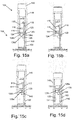
- Fig. 10a and Fig. 10b schematically show the difference between the attachment of the arms to the septum holder of the prior art and the septum holder of the present invention.
- a pair of arms is located facing each other on opposite sides of the septum holder.
- the enlarged elements at the distal end of the arms move back and forth along an extension of a diameter of the circular cross-section of the body of the septum holder in the direction shown by the double headed arrows in Fig. 10a .
- a pair of arms is located one alongside the other on the same side of the septum holder.
- the enlarged elements at the distal end of the arms move back and forth along extensions of parallel chords of the circular cross-section of the body of the septum holder in the directions shown by the double headed arrows in Fig. 10b .
- septum holder 110 is essentially identical to the prior art septum holder 58 described herein above in relation to Fig. 7a to Fig. 7c For this reason most of the structural elements of septum holder 110 are not illustrated herein and the reader is directed to Fig. 7a, Fig. 7b , and Fig. 7c to see the corresponding structure in the prior art. It is noted that other prior art septum housings, for example the other embodiments described in the above referenced IL 23788 , can be adapted mutatis mutandis , by locating the arms as described with reference to Figs. 9a and 9b . It is also noted that septum housings according to this invention can be manufactured having only one arm or more than four arms. A very stable configuration can be obtained by the use of three arms, although this would be a more complex embodiment to manufacture.
- Fig. 11a symbolically shows an adapter component 106 for connection to a septum holder 110 having two arms according to an exemplary embodiment of the present invention.
- the distal (lower portion) of adapter component 106 is adapted to connect to the second component of the fluid transfer apparatus and is not relevant to the present invention.
- the interior of the hollow elongated extension 122 of adapter component 106 contains a channel or channels to allow fluid communication between the interior of the second component of the fluid transfer system and the needles in the connector component 104, when connector component 104 and adapter component 106 are connected.
- a septum 124 at the top of the elongated extension seals the interior channels when adapter component 106 is not connected to another element of a fluid transfer apparatus.
- elongated extension 122 is significantly different from that of prior art adapter elements (see for example Fig. 5b ).
- a vertical groove 130 On the exterior surface are created - for each of the two arms, a vertical groove 130, a cut-out portion 128, and a step-like structure 126a.
- the functional parts of section 126a are planar vertical surface 126b, planar vertical surface 126c, and planar horizontal bottom surface 126d. The functions of these parts of 126a will be described in more detail herein below.
- Fig. 11b schematically shows the elongated extension 122 of the adapter component of Fig. 11a connected to septum holder 110.
- Elongated extension 122 comprises groove 130 and cut-out portion 128 in which the enlarged element 120 at the distal end of arm 118 can move. If the diameter of the elongated extension 122 is small enough, then groove 130 is not necessary. When the connection is complete, the flat upper surface of the pointed front side of enlarged element 120 is caught under the flat lower surface 126d of 126b locking the septum holder 110 and adapter 106 together.
- Fig. 12a symbolically shows an adapter component 106 for connection to a septum holder 110 having four arms according to an exemplary embodiment of the present invention.
- a projecting "house-shaped" structure inside a cut-out portion 134 on opposite sides of the outer surface of the proximal end of the elongated extension 122.
- Fig. 12b schematically shows the adapter component of Fig. 12a connected to a septum holder 110.
- the enlarged elements 120 at the distal ends of arms 118 fit into the cut-out portion 134.
- the flat upper surface of the "toes" of enlarged elements 120 are caught under the flat lower surface of "house” 132 locking the septum holder 110 and adapter component 106 together.
- Fig. 13 shows an adapter component 136 for connecting a to a spike port of an IV bag.
- Adapter component 136 has an elongated extension 138 whose upper part has the same structure as shown in Fig. 11a ; thereby allowing a septum holder such as shown in Fig. 9b to be attached to adapter component 136.
- Fig. 14 schematically shows the exterior of connector component 104.
- the internal elements of connector 104 i.e. the septum holder and one or two needles, are surrounded by an outer housing 140.
- Outer housing 140 has the shape of a right prism with a generally square cross-section and an open distal (bottom) end into which the proximal end of elongated extension 122 of adapter component 106 can be inserted.
- the proximal (upper) part 142 of outer housing 140 can be constructed in many ways in order to connect to a first component, e.g. a syringe or an IV line, of a fluid transfer apparatus.
- proximal part 138 can be constructed include: a bore having a straight or tapered interior wall into which a matching cylindrical or conical projection on the component of the fluid transfer device can be press fitted, glued, or laser or ultrasound welded; standard male or female Luer type connectors; or newly designed Luer connectors that allow uni-directional or bi-directional swiveling of the component of the fluid transfer device around the vertical symmetry axis of the outer housing 140 of the connector 104.
- the swivel type connectors will be described herein below with reference to Figs. 16a-20a .
- Fig. 15a to Fig. 15d symbolically show different stages in the connection of a connector component 104 of the invention to an adapter component 106 of the invention.
- the connection is done by pushing the two components together and the "steps" of the process are similar.
- the process is illustrated as a series of steps, in actual practice it is carried out with one continuous smooth action.
- the connector component has been rotated and part of outer housing 140 has been removed to allow one arm 118 of septum holder 110 to be seen. The one or two needles are not shown.
- Fig. 15a the proximal end of elongated extension 122 of adapter component 106 has been inserted into the open distal end of outer housing 140.
- Septum 116 of the connector component has not yet contacted septum 124 of the adapter section and the arm 120 is in its normal relaxed configuration with the rounded rear side of the enlarged element 120 in a socket 146 that is created at the distal end of outer housing 140 (see Fig. 15d ).
- the socket 146 is part of a guiding channel 113 that is formed as a cavity in the interior surface or as a rib extending from the interior surface of the plastic outer housing 140. Guiding channel 113 guides and positions the rounded rear side of the enlarged element 120 according the respective operation steps.
- Another corresponding guiding channel 111 which is made in a similar manner to channel 113, guides the planar vertical surface 126b, which glides along it.
- the sockets 146 and guiding channels 111 and 113 are not formed on the interior wall of the outer housing but are constructed in a frame-like structure that is supported within the outer housing.
- Fig. 15b the two septa 116 and 124 are in the middle of the process of being pressed against each other, but the septum holder 110 has not started to move upwards inside outer housing 140 because the enlarged element 120 remains immovably trapped inside of socket 146 with its rounded rear side inside of socket 146 and the tip of its pointed front side pressed against the vertical surface 126c of element 126a on the adapter component. Enlarged element 120 will remain trapped until the septa are fully pressed together and only then it will be released for movement. Although the enlarged element 120 is pressing on the vertical surface 126c, the vertical surface 126c which is part of element 126a is prevented from moving sidewards because the planar vertical surface 126b is pressed against guiding channel 111. The vertical surface 126b of the elongated extension 122 of adapter component 106 glides along the channel 111 inside outer housing 140 and thereby dictates straight axial motion of the components during the connection (and disconnection) process.
- elongated extension 122 of adapter component 106 has advanced far enough into the interior of connector component 104 that the force of the two septa pressing against each other forces septa holder 110 to start moving upward.
- the upper surface of the rounded rear side of enlarged element 120 slides along a sloped upper surface of socket 146 pushing the pointed front side of enlarged element 120 against vertical surface 126c of element 126a on the adapter component.
- elongated extension 122 moves up relative to septum housing far enough so that the pointed front side of enlarged element 120 at the end of arm 118 passes the bottom of vertical surface 126c.
- Fig. 15d the upper part of the pointed front side of enlarged element 120 is hooked under the horizontal bottom surface 126d of element 126a on the elongated extension 122 of adapter component 106.
- the septum holder 110 and adapter component 106 continue to move up inside outer housing 140 of connector section coupled together.
- ribs 144 that are formed on the inside of the outer housing 140 to provide mechanical strength.
- the exemplary embodiment of the septum holder shown in Fig. 12a and Fig. 12b has four arms 120, which are actually two pairs of arms.
- This embodiment provides a balance of forces in comparison to the embodiment of septum holder shown in Fig. 15a to Fig. 15d that comprises two arms only.
- each of the arms 120 in a pair of arms in Fig. 12a and Fig. 12b presses on one side of the flat side surface of "house” 132 and tries to rotate it sideward. But since there are pairs of arms that work in opposing directions, the force that is applied by one arm is neutralized by the force applied by the other arm of the pair.
- the balanced pair of arms pressing one against the other eliminates the need for an equivalent component to gliding channel 111 inside the outer housing 140 and the planar vertical surface 126b as shown in Fig. 15a to Fig. 15d .
- the problem occurs when the body is deformed due to the side forces that the enlarged elements are applying on the inner walls of the connector body. This deformation simulates the distal shoulder portion and the enlarged elements release the adapter too early, i.e. before the enlarged elements reach their destination in the distal shoulder portion and remain in a position that is a little too deep inside the connector after the adapter has been released.
- the disconnection seems at first glance to be properly executed, but the reality is that since the enlarged elements were left too deep inside the connector body, when another connection is to be made the adapter will not slide between the enlarged elements and be held by them. In the contrary, the enlarged elements will be pushed by the adapter inside the body without creating any connection and the needles will pierce the membranes and appear exposed to the environment and possibly leak while breaking the closed system.
- An advantage of the new connector component 104 is that it doesn't rely on the stability of the connector body, since the arms and enlarged elements slide in the channels 111 and 113 formed by the rigid ribs that are formed on the inside of the outer housing 140. Unlike the prior art each arm and enlarged element has its own set of independent guiding channels and can operate independently from other arms and guiding channels and the forces that the enlarged elements apply don't deform the outer housing or the guiding channels.
- Another advantage of the new connector component is that the design allows for construction of a smaller connector and respective adapter since, amongst other factors there is no need for the bulky distal shoulder portion of the prior art connector. Size is a crucial factor with users since smaller products are easier to handle and will be preferred in most applications.
- Fig. 16a to Fig. 19 schematically show an embodiment of the proximal end of a connector that comprises a mechanical arrangement that allows uni and bi-directional swiveling of a component of a fluid transfer apparatus attached to the connector.
- a special female Luer lock is provided on the proximal end of the connector and any device such as infusion tubing or a syringe with male Luer lock can be attached to it by a clockwise twisting motion.
- any device such as infusion tubing or a syringe with male Luer lock can be attached to it by a clockwise twisting motion.
- rotation of the female Luer element of the connector is prevented as will be described herein below, thereby allowing the male Luer element to be rotated until the connection is tight and no further twisting is necessary or possible.
- Fig. 16a shows a connector component 104 of the present invention adapted as a swivel connector.
- Proximal end 142 of outer housing 140 is a specially designed female Luer element 148 with external threads 150 to which a male Luer element can be connected.
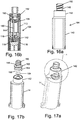
- Fig. 16b is a cross-sectional view of Fig. 16a .
- Seen in Fig. 16b are teeth 152 on the inner wall of proximal end 142 that hold Luer element 148 inside of connector component 104 and the channels 113 in which the arms 118 of the septum holder 110 move as the septum holder moves up and down inside the connector element.
- needle holder 168 that attaches the proximal end of needle 166 to the outer housing of the connector component.
- the tip of needle 166 is located inside of the insert in the body of the septum holder.
- Fig. 17a shows a prior art connector 14 modified to have a proximal end 142 according to an exemplary embodiment of the present invention.
- Area A in which a section of the wall of proximal end is removed to show the internal elements, is enlarged in Fig. 19 .
- Fig, 17b is an exploded view showing the main parts of which the swivel connector is assembled and how the bottom of the Luer element is designed.
- the swivel connector is comprised of a connector 14 (or 104) as described herein above, whose upper end has been modified, the female Luer element 148, and an O-ring, which prevents leakage of fluid between the connector body and Luer element in the assembled swivel connector.
- the bottom of Luer element 148 comprises an upper flange 162 and a lower flange 154 with an annular space 160 between them.
- Flange 154 has one or more (typically four) teeth 156 on its lower surface that are part of the swivel mechanism.
- Fig. 18 is a cross-sectional view of the proximal end 142 of the connector housing.
- the modifications made to this part of the connector include the creation of one or more (typically four) teeth 152 near the top of the inside wall; a support structure 157, which comprises a seat for O-ring 164 and a recess to accommodate the lower end of Luer element 148; and one or more (typically four) teeth 158 created on a horizontal flange near the bottom of support structure 157.
- Luer element 148 is pushed into the recess in the proximal end 140 of the connector housing. All parts of the Luer element and the connector housing are made of plastic that has enough resilience that flange 154 on the bottom of the Luer element can be forced past teeth 152, which move into space 160 holding the Luer element and housing of the connector together.
- teeth 158 on the support structure 157 of the housing of the connector have a triangular shape with an upper surface that slopes upwards in a counterclockwise direction and ends at a vertical back surface and the teeth 156 on the bottom of flange 154 have an upper surface that slopes upwards in a clockwise direction and ends at a vertical back surface. If it is attempted to swivel Luer element 148 relative to the connector housing in the counterclockwise direction, then the sloping surfaces of teeth 154 and 156 will slide over each other and Luer element 148 will rise relative to the connector housing until these surfaces pass each other and then the Luer element will drop down and can continue to turn until the next pair of teeth encounter each other when the process repeats. On the other hand, if it is attempted to swivel Luer element 148 in the clockwise direction, then the vertical surfaces on teeth 154 and 156 will butt up against each other preventing relative motion between the Luer element and connector housing in this direction.
- the distance "h” between the bottom of teeth 152 and the top of flange 154 allows the Luer element 148 to be lifted the height of "h” and swiveled clockwise; because, when the Luer element 148 is lifted to height "h” the teeth 152 and 158 are separated from each other so they can't interact with each other.
- the teeth will engage each other and rotation clockwise will tighten even more the connection between the male and female Luer elements until it is not possible to twist anymore.
- This uni and bi-directional swivel feature prevents unintended disconnection of tubing or a syringe that has been Luer-locked to a connector, which is a not uncommon problem that occurs in the prior art.
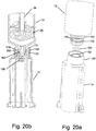
- Fig. 20a and Fig, 20b schematically show an exemplary embodiment of the proximal end of a connector that allows bi-directional swiveling of a syringe that is attached to it.
- This syringe-connector unit is factory assembled and can comprise all embodiments of both the prior art connectors described in the background section of this application and the new connector components described herein.
- Fig. 20a is an exploded view showing the components of the syringe-connector assembly.
- the throat at the bottom of the syringe is manufactured so that it comprises two flanges 170 and 172 with an annular space 174 between them.
- the proximal end 142 of the housing 14 (or 140) of the connector is manufactured with at least one tooth projecting inwards from near the top of the inner wall of the proximal end 142 of its housing.
- Fig. 20b is a cross-sectional view showing the factory assembled syringe-connector unit.
- the O-ring 164 is placed in its seat, the distal end of the syringe 12 and the proximal end 142 of the connector are pushed together with sufficient force to allow the plastic parts to flex enough so that flange 170 passes teeth 152 and the teeth are located in annular space 174 holding syringe 12 and connector 14 together.
- the O-ring prevents leakage of fluid between the connector body and syringe and the syringe is now able to swivel freely in both clockwise and counterclockwise directions relative to the connector.
- This swivel feature in the factory assembled syringe with connector is an improvement in comparison to prior art's stiff welded syringe with connector.
- One advantage is that when a Luer-lock-adapter (a component of a drug transfer system) is screwed on an infusion tubing and a prior art syringe with connector is connected to the adapter, it could happen that the user will unscrew the adapter by rotating the attached syringe. This can happen because hospital personnel are used to screw or unscrew (Luer-lock or un-Luer) most of the equipment in the hospital. It can also happen when the user, e.g. pharmacist or nurse, twists the syringe in order to read the measurement marks. With the swivel design the syringe will spin in relation to the connector, unscrewing will be prevented and the user, can easily and safely rotate the syringe to have an unobstructed view of the measurement markings on it.
- Fig. 21a schematically shows the proximal end of a prior art syringe.
- a lid 180 is snapped over the flange 176 that forms the finger grip at the top of the syringe barrel 18.
- An O-ring around piston shaft 24 and a gasket 182 isolate the interior of the syringe from the outside.
- Fig. 21b to Fig. 21d schematically show the proximal end of an embodiment of a method of sealing the distal end of the syringe according to the invention.
- This sealing element comprises a disk shaped annular sealing assembly 184 having a hole in its center through which piston rod 24 passes.
- This embodiment is comprised of an upper part 184a and a lower part 184b that are pressed together to hold an O-ring that seals around the piston rod.
- the sealing assembly is pushed into the top of the barrel of the syringe as shown in Fig. 21c and Fig. 21d .
- the sealing assembly 184 is then held in place and sealed to the inside of the syringe barrel by laser or ultrasound welding, heat welding or gluing at the location indicated by the arrows in Fig. 21c .
- the sealing assembly 184 can be press fitted into the barrel and held in place by friction and the lateral forces exerted by the sides of the plastic barrel and the sealing assembly against each other.
- a notch 186 in the sealing assembly can snap into a ridge 188 on the inside wall of the syringe barrel.
- Embodiments of standard syringes that are not used in closed transfer systems can have a design that is not airtight, e.g. they can be provided with ventilation holes that are either open directly to the surroundings or protected by filters.
- the sealing assembly 184 provides a solution to the prior art problem because it is placed inside the barrel and doesn't disturb the external shape of the syringe. Therefore it is compatible with syringe pumps and other medical equipment. Furthermore, it is easier to manufacture and in airtight applications it saves a whole component and its assembly, namely, the insertion of sealing ring between the lid and the barrel, which is difficult to accomplish correctly, is eliminated.
Landscapes
- Health & Medical Sciences (AREA)
- Veterinary Medicine (AREA)
- Life Sciences & Earth Sciences (AREA)
- Animal Behavior & Ethology (AREA)
- General Health & Medical Sciences (AREA)
- Public Health (AREA)
- Pharmacology & Pharmacy (AREA)
- Hematology (AREA)
- Heart & Thoracic Surgery (AREA)
- Fluid Mechanics (AREA)
- Physics & Mathematics (AREA)
- Anesthesiology (AREA)
- Biomedical Technology (AREA)
- Engineering & Computer Science (AREA)
- Vascular Medicine (AREA)
- Pulmonology (AREA)
- Infusion, Injection, And Reservoir Apparatuses (AREA)
- Medical Preparation Storing Or Oral Administration Devices (AREA)
Priority Applications (2)
| Application Number | Priority Date | Filing Date | Title |
|---|---|---|---|
| EP20179526.7A EP3725347A1 (en) | 2015-06-11 | 2016-06-06 | Swivel-connector between syringe and fluid transfer device |
| EP20179541.6A EP3733230A1 (en) | 2015-06-11 | 2016-06-06 | Sealing element for proximal end of a syringe |
Applications Claiming Priority (2)
| Application Number | Priority Date | Filing Date | Title |
|---|---|---|---|
| IL239366A IL239366B (en) | 2015-06-11 | 2015-06-11 | Components of a fluid transfer device |
| PCT/IL2016/050590 WO2016199133A1 (en) | 2015-06-11 | 2016-06-06 | Improved components of a fluid transfer apparatus |
Related Child Applications (4)
| Application Number | Title | Priority Date | Filing Date |
|---|---|---|---|
| EP20179526.7A Division EP3725347A1 (en) | 2015-06-11 | 2016-06-06 | Swivel-connector between syringe and fluid transfer device |
| EP20179526.7A Division-Into EP3725347A1 (en) | 2015-06-11 | 2016-06-06 | Swivel-connector between syringe and fluid transfer device |
| EP20179541.6A Division EP3733230A1 (en) | 2015-06-11 | 2016-06-06 | Sealing element for proximal end of a syringe |
| EP20179541.6A Division-Into EP3733230A1 (en) | 2015-06-11 | 2016-06-06 | Sealing element for proximal end of a syringe |
Publications (3)
| Publication Number | Publication Date |
|---|---|
| EP3307356A1 EP3307356A1 (en) | 2018-04-18 |
| EP3307356A4 EP3307356A4 (en) | 2019-04-24 |
| EP3307356B1 true EP3307356B1 (en) | 2020-07-22 |
Family
ID=55022888
Family Applications (3)
| Application Number | Title | Priority Date | Filing Date |
|---|---|---|---|
| EP20179526.7A Pending EP3725347A1 (en) | 2015-06-11 | 2016-06-06 | Swivel-connector between syringe and fluid transfer device |
| EP20179541.6A Pending EP3733230A1 (en) | 2015-06-11 | 2016-06-06 | Sealing element for proximal end of a syringe |
| EP16807024.1A Active EP3307356B1 (en) | 2015-06-11 | 2016-06-06 | Improved components of a fluid transfer apparatus |
Family Applications Before (2)
| Application Number | Title | Priority Date | Filing Date |
|---|---|---|---|
| EP20179526.7A Pending EP3725347A1 (en) | 2015-06-11 | 2016-06-06 | Swivel-connector between syringe and fluid transfer device |
| EP20179541.6A Pending EP3733230A1 (en) | 2015-06-11 | 2016-06-06 | Sealing element for proximal end of a syringe |
Country Status (10)
| Country | Link |
|---|---|
| US (3) | US10881583B2 (es) |
| EP (3) | EP3725347A1 (es) |
| JP (4) | JP6803342B2 (es) |
| CN (3) | CN113368345A (es) |
| AU (3) | AU2020227000B2 (es) |
| CA (3) | CA3180631A1 (es) |
| ES (1) | ES2811312T3 (es) |
| HK (1) | HK1251189A1 (es) |
| IL (1) | IL239366B (es) |
| WO (1) | WO2016199133A1 (es) |
Families Citing this family (22)
| Publication number | Priority date | Publication date | Assignee | Title |
|---|---|---|---|---|
| US7547300B2 (en) | 2006-04-12 | 2009-06-16 | Icu Medical, Inc. | Vial adaptor for regulating pressure |
| AU2012296495B2 (en) | 2011-08-18 | 2016-03-10 | Icu Medical, Inc. | Pressure-regulating vial adaptors |
| AU2013204180B2 (en) | 2012-03-22 | 2016-07-21 | Icu Medical, Inc. | Pressure-regulating vial adaptors |
| US9089475B2 (en) | 2013-01-23 | 2015-07-28 | Icu Medical, Inc. | Pressure-regulating vial adaptors |
| JP6617101B2 (ja) | 2013-07-19 | 2019-12-04 | アイシーユー メディカル インコーポレイテッド | 圧力調整流体移注システムおよび方法 |
| CA2953229C (en) | 2014-06-20 | 2024-01-02 | Icu Medical, Inc. | Pressure-regulating vial adaptors |
| IL243108B (en) | 2015-12-22 | 2018-08-30 | Kriheli Marino | Part of a friend |
| EP4043001A1 (en) | 2016-01-29 | 2022-08-17 | ICU Medical, Inc. | Pressure-regulating vial adaptors |
| AU2017335746A1 (en) | 2016-09-30 | 2019-04-11 | Icu Medical, Inc. | Pressure-regulating vial access devices and methods |
| EP3626283B1 (en) * | 2017-05-19 | 2022-01-19 | Advcare Medical, Inc. | Sealed medication dispensing and administering device |
| US11266571B2 (en) | 2017-08-10 | 2022-03-08 | Simplivia Healthcare Ltd. | Syringe adaptor and complementary fluid-port adaptor |
| EP3668475A1 (en) * | 2017-08-15 | 2020-06-24 | Becton, Dickinson and Company | Spinning female luer with threadably removable feature |
| IL257778B (en) * | 2018-02-27 | 2022-07-01 | Equashield Medical Ltd | Device for securing device connections |
| IL261024B2 (en) * | 2018-08-07 | 2023-07-01 | Equashield Medical Ltd | Buffer holder with movable buffer |
| FR3087116A1 (fr) * | 2018-10-10 | 2020-04-17 | Crossject | Dispositif pour le maintien de tubes de dispositif d’injection |
| EP3750574B1 (de) | 2019-06-13 | 2024-01-03 | Trenta2 S.r.l. | Flüssigkeitstransfersystem und komponenten dafür |
| JP2022539159A (ja) * | 2019-07-01 | 2022-09-07 | ウエスト ファーマスーティカル サービシーズ インコーポレイテッド | シリンジからの流体流量を測定するためのシステム及び方法 |
| IL268368B2 (en) * | 2019-07-30 | 2023-11-01 | Equashield Medical Ltd | Ingredients for open systems of liquid drug delivery and a robotic system that utilizes them |
| CN111135453A (zh) * | 2020-03-06 | 2020-05-12 | 安徽天康医疗科技股份有限公司 | 一种胃肠道应用小口径连接器用开启即毁帽盖 |
| DE102020202939A1 (de) | 2020-03-06 | 2021-09-09 | B. Braun Melsungen Aktiengesellschaft | Kupplungselement für ein geschlossenes Fluidtransfersystem, Gegenkupplungselement für ein solches Kupplungselement sowie Kupplungssystem |
| DE102021108157A1 (de) | 2021-03-31 | 2022-10-06 | B. Braun Melsungen Aktiengesellschaft | Fluidtransfervorrichtung und geschlossenes Arzneimitteltransfersystem |
| WO2023170680A1 (en) | 2022-03-08 | 2023-09-14 | Equashield Medical Ltd | Fluid transfer station in a robotic pharmaceutical preparation system |
Family Cites Families (44)
| Publication number | Priority date | Publication date | Assignee | Title |
|---|---|---|---|---|
| US3543967A (en) | 1968-06-18 | 1970-12-01 | James A O Connor | Device for packaging two separate substances |
| US3581956A (en) * | 1968-09-26 | 1971-06-01 | Hamilton Co | Syringe plunger head |
| US4030498A (en) * | 1974-10-25 | 1977-06-21 | Baxter Travenol Laboratories, Inc. | Syringe |
| JPS5640436Y2 (es) | 1976-03-29 | 1981-09-21 | ||
| US5489266A (en) * | 1994-01-25 | 1996-02-06 | Becton, Dickinson And Company | Syringe assembly and method for lyophilizing and reconstituting injectable medication |
| DE4434644C2 (de) | 1994-09-28 | 1997-08-07 | Schott Glaswerke | Behältnis zur Lagerung und Verabreichung von Injektions-, Infusions- und Diagnostikpräparaten |
| JPH09173449A (ja) | 1995-12-22 | 1997-07-08 | Jms Co Ltd | 薬液微量注入装置 |
| US6193695B1 (en) * | 2000-01-14 | 2001-02-27 | Wayland J. Rippstein, Jr. | Disposable safety syringe having a retractable needle |
| US6387078B1 (en) | 2000-12-21 | 2002-05-14 | Gillespie, Iii Richard D. | Automatic mixing and injecting apparatus |
| CA2484061C (en) * | 2001-04-27 | 2008-07-15 | Hydrocision, Inc. | High pressure pumping cartridges for medical and surgical pumping and infusion applications |
| CN1278748C (zh) * | 2002-01-28 | 2006-10-11 | Sez株式会社 | 安全注射器 |
| EP1480707B1 (en) | 2002-02-27 | 2006-07-26 | Safeshot Technologies, LLC | Automatically retractable needle safety syringe |
| US7553294B2 (en) | 2002-05-30 | 2009-06-30 | Medrad, Inc. | Syringe plunger sensing mechanism for a medical injector |
| JP4050579B2 (ja) | 2002-09-11 | 2008-02-20 | テルモ株式会社 | プレフィルドシリンジ |
| EP1530978B1 (en) | 2002-07-02 | 2012-04-11 | Terumo Kabushiki Kaisha | Syringe and prefilled syringe |
| US6939319B1 (en) * | 2002-11-20 | 2005-09-06 | Conrad Anstead | Process and device for single use, needle-free intradermal, subcutaneous, or intramuscular injections |
| US6991608B2 (en) * | 2003-04-03 | 2006-01-31 | Becton, Dickinson And Company | Medical assembly |
| JP4381735B2 (ja) | 2003-07-03 | 2009-12-09 | 株式会社根本杏林堂 | 薬液注入システム |
| FR2869533B1 (fr) | 2004-05-03 | 2006-07-28 | Sedat Sa | Seringue pour interventions medicales et necessaire de reconstitution de substances extemporanees comportant une telle seringue |
| US7727195B2 (en) | 2004-07-01 | 2010-06-01 | West Pharmaceutical Services, Inc. | Syringe device having venting system |
| US7947020B2 (en) | 2005-05-09 | 2011-05-24 | Safeshot Technologies, Llc | Retractable safety syringe |
| US7515068B2 (en) | 2005-07-12 | 2009-04-07 | Traffic Monitoring Services, Inc. | Vehicle axle sensor |
| US20070179454A1 (en) | 2006-01-31 | 2007-08-02 | Smiths Medical Asd, Inc. | Safety needle assembly with correct medication connection |
| EP2015810A4 (en) | 2006-05-05 | 2009-04-29 | Safeshot Technologies Llc | IMPROVED SYRINGE |
| CA2684745C (en) | 2007-04-23 | 2016-06-28 | Plastmed Ltd. | Method and apparatus for contamination-free transfer of a hazardous drug |
| US7975733B2 (en) | 2007-05-08 | 2011-07-12 | Carmel Pharma Ab | Fluid transfer device |
| DE102007034871A1 (de) * | 2007-07-24 | 2009-01-29 | Lts Lohmann Therapie-Systeme Ag | Einweginjektor mit handbetätigbarem Kolben |
| JP5462277B2 (ja) * | 2008-12-15 | 2014-04-02 | カルメル ファルマ アクチボラゲット | 接続装置及び医療装置を接続装置に接続する方法 |
| EP2396237B1 (de) * | 2009-02-13 | 2014-11-19 | Medmix Systems AG | Austragvorrichtung mit tube |
| GB2470954B (en) | 2009-06-12 | 2014-04-02 | Stats Uk Ltd | Pipeline isolation plug having two modules and method for isolating for a section of pipeline |
| CN102821735B (zh) | 2010-03-30 | 2014-05-14 | 泰尔茂株式会社 | 连接器及连接器组装体 |
| US8721612B2 (en) | 2010-12-17 | 2014-05-13 | Hospira, Inc. | System and method for intermixing the contents of two containers |
| EP2545956A1 (en) * | 2011-07-15 | 2013-01-16 | Becton Dickinson France | Drug delivery device and adaptor |
| CN202207309U (zh) * | 2011-09-14 | 2012-05-02 | 重庆莱美药业股份有限公司 | 一种加药器上使用的定位推动装置 |
| WO2013053949A1 (en) * | 2011-10-14 | 2013-04-18 | Novo Nordisk Health Care Ag | Pre-assembled fluid transfer arrangement |
| ES2905224T3 (es) * | 2012-03-05 | 2022-04-07 | Becton Dickinson Co | Equipo de transferencia con aguja flotante para reconstitución de fármacos |
| EP3424824B1 (en) | 2013-02-07 | 2020-03-25 | Equashield Medical Ltd. | Improvements to a closed drug transfer system |
| US10022301B2 (en) * | 2013-03-15 | 2018-07-17 | Becton Dickinson and Company Ltd. | Connection system for medical device components |
| WO2014160781A1 (en) * | 2013-03-26 | 2014-10-02 | Alliance Partners Llc | Biological fluids concentration assembly |
| IL226281A (en) | 2013-05-09 | 2017-01-31 | Kriheli Marino | Needle valve and connectors for use in fluid transfer devices |
| WO2015164413A1 (en) * | 2014-04-21 | 2015-10-29 | Becton Dickinson and Company Limited | Fluid transfer device and packaging therefor |
| BR112016024683B1 (pt) * | 2014-04-21 | 2021-12-21 | Becton Dickinson and Company Limited | Adaptador de seringa com desengate de movimento composto e método |
| CN204092830U (zh) * | 2014-10-01 | 2015-01-14 | 王晓云 | 妇科用栓剂给药装置 |
| EP3322464A4 (en) * | 2015-07-14 | 2019-05-08 | SiO2 Medical Products, Inc. | CONVERTIBLE PISTONS AND METHODS OF ASSEMBLING THEM INTO A MEDICAL CYLINDER |
-
2015
- 2015-06-11 IL IL239366A patent/IL239366B/en active IP Right Grant
-
2016
- 2016-06-06 CN CN202110361158.1A patent/CN113368345A/zh active Pending
- 2016-06-06 US US15/579,615 patent/US10881583B2/en active Active
- 2016-06-06 CN CN202110361167.0A patent/CN113368346B/zh active Active
- 2016-06-06 CA CA3180631A patent/CA3180631A1/en active Pending
- 2016-06-06 ES ES16807024T patent/ES2811312T3/es active Active
- 2016-06-06 EP EP20179526.7A patent/EP3725347A1/en active Pending
- 2016-06-06 EP EP20179541.6A patent/EP3733230A1/en active Pending
- 2016-06-06 JP JP2017564024A patent/JP6803342B2/ja active Active
- 2016-06-06 WO PCT/IL2016/050590 patent/WO2016199133A1/en active Application Filing
- 2016-06-06 CA CA2987551A patent/CA2987551C/en active Active
- 2016-06-06 EP EP16807024.1A patent/EP3307356B1/en active Active
- 2016-06-06 CA CA3180788A patent/CA3180788A1/en active Pending
- 2016-06-06 CN CN201680046618.9A patent/CN108348688B/zh active Active
-
2018
- 2018-08-21 HK HK18110760.7A patent/HK1251189A1/zh unknown
-
2020
- 2020-08-31 AU AU2020227000A patent/AU2020227000B2/en not_active Expired - Fee Related
- 2020-08-31 AU AU2020226997A patent/AU2020226997B2/en active Active
- 2020-11-25 US US17/104,503 patent/US20210077353A1/en active Pending
- 2020-11-25 US US17/104,574 patent/US11730679B2/en active Active
- 2020-11-26 JP JP2020196100A patent/JP7108673B2/ja active Active
- 2020-11-26 JP JP2020196098A patent/JP2021049352A/ja active Pending
-
2021
- 2021-09-10 AU AU2021229229A patent/AU2021229229B2/en active Active
-
2022
- 2022-07-26 JP JP2022118501A patent/JP7431285B2/ja active Active
Non-Patent Citations (1)
| Title |
|---|
| None * |
Also Published As
Similar Documents
| Publication | Publication Date | Title |
|---|---|---|
| AU2021229229B2 (en) | Improved components of a fluid transfer apparatus | |
| US11759394B2 (en) | Septum holders for use in syringe connectors | |
| JP6392325B2 (ja) | 液体移送装置に使用するニードルバルブ及びコネクタ |
Legal Events
| Date | Code | Title | Description |
|---|---|---|---|
| STAA | Information on the status of an ep patent application or granted ep patent |
Free format text: STATUS: THE INTERNATIONAL PUBLICATION HAS BEEN MADE |
|
| PUAI | Public reference made under article 153(3) epc to a published international application that has entered the european phase |
Free format text: ORIGINAL CODE: 0009012 |
|
| STAA | Information on the status of an ep patent application or granted ep patent |
Free format text: STATUS: REQUEST FOR EXAMINATION WAS MADE |
|
| 17P | Request for examination filed |
Effective date: 20171207 |
|
| AK | Designated contracting states |
Kind code of ref document: A1 Designated state(s): AL AT BE BG CH CY CZ DE DK EE ES FI FR GB GR HR HU IE IS IT LI LT LU LV MC MK MT NL NO PL PT RO RS SE SI SK SM TR |
|
| AX | Request for extension of the european patent |
Extension state: BA ME |
|
| DAV | Request for validation of the european patent (deleted) | ||
| DAX | Request for extension of the european patent (deleted) | ||
| RIC1 | Information provided on ipc code assigned before grant |
Ipc: A61J 1/20 20060101AFI20181210BHEP Ipc: A61M 39/10 20060101ALN20181210BHEP Ipc: A61J 1/14 20060101ALI20181210BHEP |
|
| A4 | Supplementary search report drawn up and despatched |
Effective date: 20190325 |
|
| RIC1 | Information provided on ipc code assigned before grant |
Ipc: A61J 1/14 20060101ALI20190319BHEP Ipc: A61J 1/20 20060101AFI20190319BHEP Ipc: A61M 39/10 20060101ALN20190319BHEP |
|
| GRAP | Despatch of communication of intention to grant a patent |
Free format text: ORIGINAL CODE: EPIDOSNIGR1 |
|
| STAA | Information on the status of an ep patent application or granted ep patent |
Free format text: STATUS: GRANT OF PATENT IS INTENDED |
|
| RIC1 | Information provided on ipc code assigned before grant |
Ipc: A61M 5/31 20060101AFI20200107BHEP Ipc: A61M 39/10 20060101ALI20200107BHEP |
|
| INTG | Intention to grant announced |
Effective date: 20200212 |
|
| GRAS | Grant fee paid |
Free format text: ORIGINAL CODE: EPIDOSNIGR3 |
|
| GRAA | (expected) grant |
Free format text: ORIGINAL CODE: 0009210 |
|
| STAA | Information on the status of an ep patent application or granted ep patent |
Free format text: STATUS: THE PATENT HAS BEEN GRANTED |
|
| AK | Designated contracting states |
Kind code of ref document: B1 Designated state(s): AL AT BE BG CH CY CZ DE DK EE ES FI FR GB GR HR HU IE IS IT LI LT LU LV MC MK MT NL NO PL PT RO RS SE SI SK SM TR |
|
| REG | Reference to a national code |
Ref country code: GB Ref legal event code: FG4D |
|
| REG | Reference to a national code |
Ref country code: CH Ref legal event code: EP |
|
| REG | Reference to a national code |
Ref country code: DE Ref legal event code: R096 Ref document number: 602016040519 Country of ref document: DE |
|
| REG | Reference to a national code |
Ref country code: AT Ref legal event code: REF Ref document number: 1292823 Country of ref document: AT Kind code of ref document: T Effective date: 20200815 |
|
| REG | Reference to a national code |
Ref country code: IE Ref legal event code: FG4D |
|
| REG | Reference to a national code |
Ref country code: LT Ref legal event code: MG4D |
|
| REG | Reference to a national code |
Ref country code: AT Ref legal event code: MK05 Ref document number: 1292823 Country of ref document: AT Kind code of ref document: T Effective date: 20200722 |
|
| PG25 | Lapsed in a contracting state [announced via postgrant information from national office to epo] |
Ref country code: HR Free format text: LAPSE BECAUSE OF FAILURE TO SUBMIT A TRANSLATION OF THE DESCRIPTION OR TO PAY THE FEE WITHIN THE PRESCRIBED TIME-LIMIT Effective date: 20200722 Ref country code: PT Free format text: LAPSE BECAUSE OF FAILURE TO SUBMIT A TRANSLATION OF THE DESCRIPTION OR TO PAY THE FEE WITHIN THE PRESCRIBED TIME-LIMIT Effective date: 20201123 Ref country code: SE Free format text: LAPSE BECAUSE OF FAILURE TO SUBMIT A TRANSLATION OF THE DESCRIPTION OR TO PAY THE FEE WITHIN THE PRESCRIBED TIME-LIMIT Effective date: 20200722 Ref country code: AT Free format text: LAPSE BECAUSE OF FAILURE TO SUBMIT A TRANSLATION OF THE DESCRIPTION OR TO PAY THE FEE WITHIN THE PRESCRIBED TIME-LIMIT Effective date: 20200722 Ref country code: BG Free format text: LAPSE BECAUSE OF FAILURE TO SUBMIT A TRANSLATION OF THE DESCRIPTION OR TO PAY THE FEE WITHIN THE PRESCRIBED TIME-LIMIT Effective date: 20201022 Ref country code: LT Free format text: LAPSE BECAUSE OF FAILURE TO SUBMIT A TRANSLATION OF THE DESCRIPTION OR TO PAY THE FEE WITHIN THE PRESCRIBED TIME-LIMIT Effective date: 20200722 Ref country code: NO Free format text: LAPSE BECAUSE OF FAILURE TO SUBMIT A TRANSLATION OF THE DESCRIPTION OR TO PAY THE FEE WITHIN THE PRESCRIBED TIME-LIMIT Effective date: 20201022 Ref country code: GR Free format text: LAPSE BECAUSE OF FAILURE TO SUBMIT A TRANSLATION OF THE DESCRIPTION OR TO PAY THE FEE WITHIN THE PRESCRIBED TIME-LIMIT Effective date: 20201023 Ref country code: FI Free format text: LAPSE BECAUSE OF FAILURE TO SUBMIT A TRANSLATION OF THE DESCRIPTION OR TO PAY THE FEE WITHIN THE PRESCRIBED TIME-LIMIT Effective date: 20200722 |
|
| PG25 | Lapsed in a contracting state [announced via postgrant information from national office to epo] |
Ref country code: LV Free format text: LAPSE BECAUSE OF FAILURE TO SUBMIT A TRANSLATION OF THE DESCRIPTION OR TO PAY THE FEE WITHIN THE PRESCRIBED TIME-LIMIT Effective date: 20200722 Ref country code: RS Free format text: LAPSE BECAUSE OF FAILURE TO SUBMIT A TRANSLATION OF THE DESCRIPTION OR TO PAY THE FEE WITHIN THE PRESCRIBED TIME-LIMIT Effective date: 20200722 Ref country code: PL Free format text: LAPSE BECAUSE OF FAILURE TO SUBMIT A TRANSLATION OF THE DESCRIPTION OR TO PAY THE FEE WITHIN THE PRESCRIBED TIME-LIMIT Effective date: 20200722 Ref country code: IS Free format text: LAPSE BECAUSE OF FAILURE TO SUBMIT A TRANSLATION OF THE DESCRIPTION OR TO PAY THE FEE WITHIN THE PRESCRIBED TIME-LIMIT Effective date: 20201122 |
|
| REG | Reference to a national code |
Ref country code: ES Ref legal event code: FG2A Ref document number: 2811312 Country of ref document: ES Kind code of ref document: T3 Effective date: 20210311 |
|
| PG25 | Lapsed in a contracting state [announced via postgrant information from national office to epo] |
Ref country code: NL Free format text: LAPSE BECAUSE OF FAILURE TO SUBMIT A TRANSLATION OF THE DESCRIPTION OR TO PAY THE FEE WITHIN THE PRESCRIBED TIME-LIMIT Effective date: 20200722 |
|
| REG | Reference to a national code |
Ref country code: DE Ref legal event code: R097 Ref document number: 602016040519 Country of ref document: DE |
|
| PG25 | Lapsed in a contracting state [announced via postgrant information from national office to epo] |
Ref country code: EE Free format text: LAPSE BECAUSE OF FAILURE TO SUBMIT A TRANSLATION OF THE DESCRIPTION OR TO PAY THE FEE WITHIN THE PRESCRIBED TIME-LIMIT Effective date: 20200722 Ref country code: SM Free format text: LAPSE BECAUSE OF FAILURE TO SUBMIT A TRANSLATION OF THE DESCRIPTION OR TO PAY THE FEE WITHIN THE PRESCRIBED TIME-LIMIT Effective date: 20200722 Ref country code: RO Free format text: LAPSE BECAUSE OF FAILURE TO SUBMIT A TRANSLATION OF THE DESCRIPTION OR TO PAY THE FEE WITHIN THE PRESCRIBED TIME-LIMIT Effective date: 20200722 Ref country code: CZ Free format text: LAPSE BECAUSE OF FAILURE TO SUBMIT A TRANSLATION OF THE DESCRIPTION OR TO PAY THE FEE WITHIN THE PRESCRIBED TIME-LIMIT Effective date: 20200722 Ref country code: DK Free format text: LAPSE BECAUSE OF FAILURE TO SUBMIT A TRANSLATION OF THE DESCRIPTION OR TO PAY THE FEE WITHIN THE PRESCRIBED TIME-LIMIT Effective date: 20200722 |
|
| PLBE | No opposition filed within time limit |
Free format text: ORIGINAL CODE: 0009261 |
|
| STAA | Information on the status of an ep patent application or granted ep patent |
Free format text: STATUS: NO OPPOSITION FILED WITHIN TIME LIMIT |
|
| PG25 | Lapsed in a contracting state [announced via postgrant information from national office to epo] |
Ref country code: AL Free format text: LAPSE BECAUSE OF FAILURE TO SUBMIT A TRANSLATION OF THE DESCRIPTION OR TO PAY THE FEE WITHIN THE PRESCRIBED TIME-LIMIT Effective date: 20200722 |
|
| 26N | No opposition filed |
Effective date: 20210423 |
|
| PG25 | Lapsed in a contracting state [announced via postgrant information from national office to epo] |
Ref country code: SK Free format text: LAPSE BECAUSE OF FAILURE TO SUBMIT A TRANSLATION OF THE DESCRIPTION OR TO PAY THE FEE WITHIN THE PRESCRIBED TIME-LIMIT Effective date: 20200722 |
|
| PG25 | Lapsed in a contracting state [announced via postgrant information from national office to epo] |
Ref country code: SI Free format text: LAPSE BECAUSE OF FAILURE TO SUBMIT A TRANSLATION OF THE DESCRIPTION OR TO PAY THE FEE WITHIN THE PRESCRIBED TIME-LIMIT Effective date: 20200722 |
|
| REG | Reference to a national code |
Ref country code: NL Ref legal event code: MP Effective date: 20200722 |
|
| PG25 | Lapsed in a contracting state [announced via postgrant information from national office to epo] |
Ref country code: MC Free format text: LAPSE BECAUSE OF FAILURE TO SUBMIT A TRANSLATION OF THE DESCRIPTION OR TO PAY THE FEE WITHIN THE PRESCRIBED TIME-LIMIT Effective date: 20200722 |
|
| REG | Reference to a national code |
Ref country code: CH Ref legal event code: PL |
|
| PG25 | Lapsed in a contracting state [announced via postgrant information from national office to epo] |
Ref country code: LU Free format text: LAPSE BECAUSE OF NON-PAYMENT OF DUE FEES Effective date: 20210606 |
|
| PG25 | Lapsed in a contracting state [announced via postgrant information from national office to epo] |
Ref country code: LI Free format text: LAPSE BECAUSE OF NON-PAYMENT OF DUE FEES Effective date: 20210630 Ref country code: IE Free format text: LAPSE BECAUSE OF NON-PAYMENT OF DUE FEES Effective date: 20210606 Ref country code: CH Free format text: LAPSE BECAUSE OF NON-PAYMENT OF DUE FEES Effective date: 20210630 |
|
| PG25 | Lapsed in a contracting state [announced via postgrant information from national office to epo] |
Ref country code: CY Free format text: LAPSE BECAUSE OF FAILURE TO SUBMIT A TRANSLATION OF THE DESCRIPTION OR TO PAY THE FEE WITHIN THE PRESCRIBED TIME-LIMIT Effective date: 20200722 |
|
| PG25 | Lapsed in a contracting state [announced via postgrant information from national office to epo] |
Ref country code: HU Free format text: LAPSE BECAUSE OF FAILURE TO SUBMIT A TRANSLATION OF THE DESCRIPTION OR TO PAY THE FEE WITHIN THE PRESCRIBED TIME-LIMIT; INVALID AB INITIO Effective date: 20160606 |
|
| PGFP | Annual fee paid to national office [announced via postgrant information from national office to epo] |
Ref country code: IT Payment date: 20230526 Year of fee payment: 8 Ref country code: FR Payment date: 20230523 Year of fee payment: 8 Ref country code: DE Payment date: 20230524 Year of fee payment: 8 |
|
| PGFP | Annual fee paid to national office [announced via postgrant information from national office to epo] |
Ref country code: TR Payment date: 20230529 Year of fee payment: 8 |
|
| PGFP | Annual fee paid to national office [announced via postgrant information from national office to epo] |
Ref country code: BE Payment date: 20230524 Year of fee payment: 8 |
|
| PGFP | Annual fee paid to national office [announced via postgrant information from national office to epo] |
Ref country code: GB Payment date: 20230518 Year of fee payment: 8 Ref country code: ES Payment date: 20230707 Year of fee payment: 8 |
|
| PG25 | Lapsed in a contracting state [announced via postgrant information from national office to epo] |
Ref country code: MK Free format text: LAPSE BECAUSE OF FAILURE TO SUBMIT A TRANSLATION OF THE DESCRIPTION OR TO PAY THE FEE WITHIN THE PRESCRIBED TIME-LIMIT Effective date: 20200722 |