EP3307201B1 - Verfahren zum designen und zur herstellung einer halterung - Google Patents
Verfahren zum designen und zur herstellung einer halterung Download PDFInfo
- Publication number
- EP3307201B1 EP3307201B1 EP16741539.7A EP16741539A EP3307201B1 EP 3307201 B1 EP3307201 B1 EP 3307201B1 EP 16741539 A EP16741539 A EP 16741539A EP 3307201 B1 EP3307201 B1 EP 3307201B1
- Authority
- EP
- European Patent Office
- Prior art keywords
- custom
- holder
- dental implant
- implant
- data set
- Prior art date
- Legal status (The legal status is an assumption and is not a legal conclusion. Google has not performed a legal analysis and makes no representation as to the accuracy of the status listed.)
- Active
Links
Images


Classifications
-
- A—HUMAN NECESSITIES
- A61—MEDICAL OR VETERINARY SCIENCE; HYGIENE
- A61C—DENTISTRY; APPARATUS OR METHODS FOR ORAL OR DENTAL HYGIENE
- A61C19/00—Dental auxiliary appliances
- A61C19/02—Protective casings, e.g. boxes for instruments; Bags
-
- A—HUMAN NECESSITIES
- A61—MEDICAL OR VETERINARY SCIENCE; HYGIENE
- A61C—DENTISTRY; APPARATUS OR METHODS FOR ORAL OR DENTAL HYGIENE
- A61C8/00—Means to be fixed to the jaw-bone for consolidating natural teeth or for fixing dental prostheses thereon; Dental implants; Implanting tools
- A61C8/0087—Means for sterile storage or manipulation of dental implants
-
- A—HUMAN NECESSITIES
- A61—MEDICAL OR VETERINARY SCIENCE; HYGIENE
- A61F—FILTERS IMPLANTABLE INTO BLOOD VESSELS; PROSTHESES; DEVICES PROVIDING PATENCY TO, OR PREVENTING COLLAPSING OF, TUBULAR STRUCTURES OF THE BODY, e.g. STENTS; ORTHOPAEDIC, NURSING OR CONTRACEPTIVE DEVICES; FOMENTATION; TREATMENT OR PROTECTION OF EYES OR EARS; BANDAGES, DRESSINGS OR ABSORBENT PADS; FIRST-AID KITS
- A61F2/00—Filters implantable into blood vessels; Prostheses, i.e. artificial substitutes or replacements for parts of the body; Appliances for connecting them with the body; Devices providing patency to, or preventing collapsing of, tubular structures of the body, e.g. stents
- A61F2/0095—Packages or dispensers for prostheses or other implants
-
- A—HUMAN NECESSITIES
- A61—MEDICAL OR VETERINARY SCIENCE; HYGIENE
- A61L—METHODS OR APPARATUS FOR STERILISING MATERIALS OR OBJECTS IN GENERAL; DISINFECTION, STERILISATION OR DEODORISATION OF AIR; CHEMICAL ASPECTS OF BANDAGES, DRESSINGS, ABSORBENT PADS OR SURGICAL ARTICLES; MATERIALS FOR BANDAGES, DRESSINGS, ABSORBENT PADS OR SURGICAL ARTICLES
- A61L2/00—Methods or apparatus for disinfecting or sterilising materials or objects other than foodstuffs or contact lenses; Accessories therefor
- A61L2/02—Methods or apparatus for disinfecting or sterilising materials or objects other than foodstuffs or contact lenses; Accessories therefor using physical phenomena
- A61L2/04—Heat
-
- A—HUMAN NECESSITIES
- A61—MEDICAL OR VETERINARY SCIENCE; HYGIENE
- A61L—METHODS OR APPARATUS FOR STERILISING MATERIALS OR OBJECTS IN GENERAL; DISINFECTION, STERILISATION OR DEODORISATION OF AIR; CHEMICAL ASPECTS OF BANDAGES, DRESSINGS, ABSORBENT PADS OR SURGICAL ARTICLES; MATERIALS FOR BANDAGES, DRESSINGS, ABSORBENT PADS OR SURGICAL ARTICLES
- A61L2/00—Methods or apparatus for disinfecting or sterilising materials or objects other than foodstuffs or contact lenses; Accessories therefor
- A61L2/02—Methods or apparatus for disinfecting or sterilising materials or objects other than foodstuffs or contact lenses; Accessories therefor using physical phenomena
- A61L2/08—Radiation
- A61L2/081—Gamma radiation
-
- A—HUMAN NECESSITIES
- A61—MEDICAL OR VETERINARY SCIENCE; HYGIENE
- A61L—METHODS OR APPARATUS FOR STERILISING MATERIALS OR OBJECTS IN GENERAL; DISINFECTION, STERILISATION OR DEODORISATION OF AIR; CHEMICAL ASPECTS OF BANDAGES, DRESSINGS, ABSORBENT PADS OR SURGICAL ARTICLES; MATERIALS FOR BANDAGES, DRESSINGS, ABSORBENT PADS OR SURGICAL ARTICLES
- A61L2/00—Methods or apparatus for disinfecting or sterilising materials or objects other than foodstuffs or contact lenses; Accessories therefor
- A61L2/02—Methods or apparatus for disinfecting or sterilising materials or objects other than foodstuffs or contact lenses; Accessories therefor using physical phenomena
- A61L2/08—Radiation
- A61L2/087—Particle radiation, e.g. electron-beam, alpha or beta radiation
-
- A—HUMAN NECESSITIES
- A61—MEDICAL OR VETERINARY SCIENCE; HYGIENE
- A61L—METHODS OR APPARATUS FOR STERILISING MATERIALS OR OBJECTS IN GENERAL; DISINFECTION, STERILISATION OR DEODORISATION OF AIR; CHEMICAL ASPECTS OF BANDAGES, DRESSINGS, ABSORBENT PADS OR SURGICAL ARTICLES; MATERIALS FOR BANDAGES, DRESSINGS, ABSORBENT PADS OR SURGICAL ARTICLES
- A61L2/00—Methods or apparatus for disinfecting or sterilising materials or objects other than foodstuffs or contact lenses; Accessories therefor
- A61L2/02—Methods or apparatus for disinfecting or sterilising materials or objects other than foodstuffs or contact lenses; Accessories therefor using physical phenomena
- A61L2/08—Radiation
- A61L2/088—Radiation using a photocatalyst or photosensitiser
-
- A—HUMAN NECESSITIES
- A61—MEDICAL OR VETERINARY SCIENCE; HYGIENE
- A61L—METHODS OR APPARATUS FOR STERILISING MATERIALS OR OBJECTS IN GENERAL; DISINFECTION, STERILISATION OR DEODORISATION OF AIR; CHEMICAL ASPECTS OF BANDAGES, DRESSINGS, ABSORBENT PADS OR SURGICAL ARTICLES; MATERIALS FOR BANDAGES, DRESSINGS, ABSORBENT PADS OR SURGICAL ARTICLES
- A61L2/00—Methods or apparatus for disinfecting or sterilising materials or objects other than foodstuffs or contact lenses; Accessories therefor
- A61L2/02—Methods or apparatus for disinfecting or sterilising materials or objects other than foodstuffs or contact lenses; Accessories therefor using physical phenomena
- A61L2/08—Radiation
- A61L2/10—Ultraviolet radiation
-
- A—HUMAN NECESSITIES
- A61—MEDICAL OR VETERINARY SCIENCE; HYGIENE
- A61L—METHODS OR APPARATUS FOR STERILISING MATERIALS OR OBJECTS IN GENERAL; DISINFECTION, STERILISATION OR DEODORISATION OF AIR; CHEMICAL ASPECTS OF BANDAGES, DRESSINGS, ABSORBENT PADS OR SURGICAL ARTICLES; MATERIALS FOR BANDAGES, DRESSINGS, ABSORBENT PADS OR SURGICAL ARTICLES
- A61L2/00—Methods or apparatus for disinfecting or sterilising materials or objects other than foodstuffs or contact lenses; Accessories therefor
- A61L2/02—Methods or apparatus for disinfecting or sterilising materials or objects other than foodstuffs or contact lenses; Accessories therefor using physical phenomena
- A61L2/14—Plasma, i.e. ionised gases
-
- B—PERFORMING OPERATIONS; TRANSPORTING
- B65—CONVEYING; PACKING; STORING; HANDLING THIN OR FILAMENTARY MATERIAL
- B65B—MACHINES, APPARATUS OR DEVICES FOR, OR METHODS OF, PACKAGING ARTICLES OR MATERIALS; UNPACKING
- B65B51/00—Devices for, or methods of, sealing or securing package folds or closures; Devices for gathering or twisting wrappers, or necks of bags
- B65B51/10—Applying or generating heat or pressure or combinations thereof
- B65B51/22—Applying or generating heat or pressure or combinations thereof by friction or ultrasonic or high-frequency electrical means, i.e. by friction or ultrasonic or induction welding
-
- B—PERFORMING OPERATIONS; TRANSPORTING
- B65—CONVEYING; PACKING; STORING; HANDLING THIN OR FILAMENTARY MATERIAL
- B65B—MACHINES, APPARATUS OR DEVICES FOR, OR METHODS OF, PACKAGING ARTICLES OR MATERIALS; UNPACKING
- B65B55/00—Preserving, protecting or purifying packages or package contents in association with packaging
- B65B55/02—Sterilising, e.g. of complete packages
- B65B55/04—Sterilising wrappers or receptacles prior to, or during, packaging
- B65B55/06—Sterilising wrappers or receptacles prior to, or during, packaging by heat
-
- B—PERFORMING OPERATIONS; TRANSPORTING
- B65—CONVEYING; PACKING; STORING; HANDLING THIN OR FILAMENTARY MATERIAL
- B65B—MACHINES, APPARATUS OR DEVICES FOR, OR METHODS OF, PACKAGING ARTICLES OR MATERIALS; UNPACKING
- B65B7/00—Closing containers or receptacles after filling
- B65B7/16—Closing semi-rigid or rigid containers or receptacles not deformed by, or not taking-up shape of, contents, e.g. boxes or cartons
-
- B—PERFORMING OPERATIONS; TRANSPORTING
- B65—CONVEYING; PACKING; STORING; HANDLING THIN OR FILAMENTARY MATERIAL
- B65D—CONTAINERS FOR STORAGE OR TRANSPORT OF ARTICLES OR MATERIALS, e.g. BAGS, BARRELS, BOTTLES, BOXES, CANS, CARTONS, CRATES, DRUMS, JARS, TANKS, HOPPERS, FORWARDING CONTAINERS; ACCESSORIES, CLOSURES, OR FITTINGS THEREFOR; PACKAGING ELEMENTS; PACKAGES
- B65D17/00—Rigid or semi-rigid containers specially constructed to be opened by cutting or piercing, or by tearing of frangible members or portions
- B65D17/50—Non-integral frangible members applied to, or inserted in, preformed openings, e.g. tearable strips or plastic plugs
- B65D17/501—Flexible tape or foil-like material
-
- B—PERFORMING OPERATIONS; TRANSPORTING
- B65—CONVEYING; PACKING; STORING; HANDLING THIN OR FILAMENTARY MATERIAL
- B65D—CONTAINERS FOR STORAGE OR TRANSPORT OF ARTICLES OR MATERIALS, e.g. BAGS, BARRELS, BOTTLES, BOXES, CANS, CARTONS, CRATES, DRUMS, JARS, TANKS, HOPPERS, FORWARDING CONTAINERS; ACCESSORIES, CLOSURES, OR FITTINGS THEREFOR; PACKAGING ELEMENTS; PACKAGES
- B65D25/00—Details of other kinds or types of rigid or semi-rigid containers
- B65D25/02—Internal fittings
- B65D25/10—Devices to locate articles in containers
-
- B—PERFORMING OPERATIONS; TRANSPORTING
- B65—CONVEYING; PACKING; STORING; HANDLING THIN OR FILAMENTARY MATERIAL
- B65D—CONTAINERS FOR STORAGE OR TRANSPORT OF ARTICLES OR MATERIALS, e.g. BAGS, BARRELS, BOTTLES, BOXES, CANS, CARTONS, CRATES, DRUMS, JARS, TANKS, HOPPERS, FORWARDING CONTAINERS; ACCESSORIES, CLOSURES, OR FITTINGS THEREFOR; PACKAGING ELEMENTS; PACKAGES
- B65D7/00—Containers having bodies formed by interconnecting or uniting two or more rigid, or substantially rigid, components made wholly or mainly of metal
- B65D7/02—Containers having bodies formed by interconnecting or uniting two or more rigid, or substantially rigid, components made wholly or mainly of metal characterised by shape
- B65D7/06—Containers having bodies formed by interconnecting or uniting two or more rigid, or substantially rigid, components made wholly or mainly of metal characterised by shape of polygonal cross-section, e.g. tins, boxes
- B65D7/08—Trays or like containers without lids
-
- A—HUMAN NECESSITIES
- A61—MEDICAL OR VETERINARY SCIENCE; HYGIENE
- A61B—DIAGNOSIS; SURGERY; IDENTIFICATION
- A61B50/00—Containers, covers, furniture or holders specially adapted for surgical or diagnostic appliances or instruments, e.g. sterile covers
- A61B50/30—Containers specially adapted for packaging, protecting, dispensing, collecting or disposing of surgical or diagnostic appliances or instruments
- A61B2050/3015—Containers specially adapted for packaging, protecting, dispensing, collecting or disposing of surgical or diagnostic appliances or instruments transparent
-
- A—HUMAN NECESSITIES
- A61—MEDICAL OR VETERINARY SCIENCE; HYGIENE
- A61C—DENTISTRY; APPARATUS OR METHODS FOR ORAL OR DENTAL HYGIENE
- A61C2202/00—Packaging for dental appliances
-
- A—HUMAN NECESSITIES
- A61—MEDICAL OR VETERINARY SCIENCE; HYGIENE
- A61C—DENTISTRY; APPARATUS OR METHODS FOR ORAL OR DENTAL HYGIENE
- A61C8/00—Means to be fixed to the jaw-bone for consolidating natural teeth or for fixing dental prostheses thereon; Dental implants; Implanting tools
- A61C8/0018—Means to be fixed to the jaw-bone for consolidating natural teeth or for fixing dental prostheses thereon; Dental implants; Implanting tools characterised by the shape
- A61C8/0036—Tooth replica
-
- A—HUMAN NECESSITIES
- A61—MEDICAL OR VETERINARY SCIENCE; HYGIENE
- A61L—METHODS OR APPARATUS FOR STERILISING MATERIALS OR OBJECTS IN GENERAL; DISINFECTION, STERILISATION OR DEODORISATION OF AIR; CHEMICAL ASPECTS OF BANDAGES, DRESSINGS, ABSORBENT PADS OR SURGICAL ARTICLES; MATERIALS FOR BANDAGES, DRESSINGS, ABSORBENT PADS OR SURGICAL ARTICLES
- A61L2202/00—Aspects relating to methods or apparatus for disinfecting or sterilising materials or objects
- A61L2202/10—Apparatus features
- A61L2202/11—Apparatus for generating biocidal substances, e.g. vaporisers, UV lamps
-
- A—HUMAN NECESSITIES
- A61—MEDICAL OR VETERINARY SCIENCE; HYGIENE
- A61L—METHODS OR APPARATUS FOR STERILISING MATERIALS OR OBJECTS IN GENERAL; DISINFECTION, STERILISATION OR DEODORISATION OF AIR; CHEMICAL ASPECTS OF BANDAGES, DRESSINGS, ABSORBENT PADS OR SURGICAL ARTICLES; MATERIALS FOR BANDAGES, DRESSINGS, ABSORBENT PADS OR SURGICAL ARTICLES
- A61L2202/00—Aspects relating to methods or apparatus for disinfecting or sterilising materials or objects
- A61L2202/10—Apparatus features
- A61L2202/18—Aseptic storing means
-
- A—HUMAN NECESSITIES
- A61—MEDICAL OR VETERINARY SCIENCE; HYGIENE
- A61L—METHODS OR APPARATUS FOR STERILISING MATERIALS OR OBJECTS IN GENERAL; DISINFECTION, STERILISATION OR DEODORISATION OF AIR; CHEMICAL ASPECTS OF BANDAGES, DRESSINGS, ABSORBENT PADS OR SURGICAL ARTICLES; MATERIALS FOR BANDAGES, DRESSINGS, ABSORBENT PADS OR SURGICAL ARTICLES
- A61L2202/00—Aspects relating to methods or apparatus for disinfecting or sterilising materials or objects
- A61L2202/20—Targets to be treated
- A61L2202/21—Pharmaceuticals, e.g. medicaments, artificial body parts
-
- A—HUMAN NECESSITIES
- A61—MEDICAL OR VETERINARY SCIENCE; HYGIENE
- A61L—METHODS OR APPARATUS FOR STERILISING MATERIALS OR OBJECTS IN GENERAL; DISINFECTION, STERILISATION OR DEODORISATION OF AIR; CHEMICAL ASPECTS OF BANDAGES, DRESSINGS, ABSORBENT PADS OR SURGICAL ARTICLES; MATERIALS FOR BANDAGES, DRESSINGS, ABSORBENT PADS OR SURGICAL ARTICLES
- A61L2202/00—Aspects relating to methods or apparatus for disinfecting or sterilising materials or objects
- A61L2202/20—Targets to be treated
- A61L2202/23—Containers, e.g. vials, bottles, syringes, mail
-
- A—HUMAN NECESSITIES
- A61—MEDICAL OR VETERINARY SCIENCE; HYGIENE
- A61L—METHODS OR APPARATUS FOR STERILISING MATERIALS OR OBJECTS IN GENERAL; DISINFECTION, STERILISATION OR DEODORISATION OF AIR; CHEMICAL ASPECTS OF BANDAGES, DRESSINGS, ABSORBENT PADS OR SURGICAL ARTICLES; MATERIALS FOR BANDAGES, DRESSINGS, ABSORBENT PADS OR SURGICAL ARTICLES
- A61L2202/00—Aspects relating to methods or apparatus for disinfecting or sterilising materials or objects
- A61L2202/20—Targets to be treated
- A61L2202/24—Medical instruments, e.g. endoscopes, catheters, sharps
Definitions
- the present invention relates generally to the field of implantology, and more particularly to the field of dental restorations, implants and in particular to a method for design and manufacturing of a holder.
- Packaging solutions for implants are required to avoid or at least minimize any contact between the implant's surface and the packaging materials during transportation, so that the materials of the packaging do not damage or alter the implant, for example by the packaging contacting the implant's surfaces, and rubbing off portions of the surface or by otherwise contaminating the implant surfaces.
- Sterilization of packaged products is the generally accepted standard for medical devices, and implants in particular.
- the packaging provides a sterile barrier that maintains sterilization during transportation and shelf life. Sterilization with moist heat, or other toxic gases, requires semi-permeable packaging components so that the sterilization agent is able to infiltrate and saturate the packaging volume and reach at least the surfaces of the medical device, or implant, in order to provide the level of bacterial overkill required by law or regulatory bodies. Volumetric sterilization methods like gamma radiation may damage or deteriorate material properties and cannot be used for certain medical devices.
- Environmental air surrounding a medical device or implant including fumes, pollution, and gas components that evaporate from packaging materials contaminate refined surfaces of medical devices within packaging containers.
- Purified surfaces "age" within hours and days being exposed to environmental air, so that, for example hydrocarbons are spreading out in cumulating molecular layers on implant surfaces, turning clean and refined hydrophilic surfaces, available directly after manufacturing processes, for example after etching of endosseous implant surfaces, into hydrophobic surface properties.
- the initial immediate and direct contact between refined implant surfaces and blood proteins is considered to enhance the hard and soft tissue integration.
- Hydrophobic surfaces and surfaces contaminated with hydrocarbons, for example from packaging emissions, are considered detrimental to that enhancement.
- the implant consists of titanium or a titanium alloy.
- the implant is provided with a rough "hydroxylated and hydrophilic surface which is at least sealed in a gastight and liquid-tight covering.
- the interior of said covering is provided with an inert atmosphere, preferably consisting of nitrogen, oxygen and/or inert gas and/or is at least partially filled with purified water," which optionally contains additives.
- Korean Publication KR 2010 0034372 A discloses a fixing grip for an implant fixture to improve packing ability of the fixture into a sterilized state, and to improve surgical operation convenience by simply separate the fixture.
- the fixing grip comprises two bases formed to be symmetrical.
- US Publication US 2005/0350015 A1 describes a packaging for a dental implant.
- the packaging has a rigid enclosure and an implant holder situated therein.
- the enclosure is able to stand on two different planes.
- the enclosure has a receptacle for the implant holder, an opening for access to the implant holder, and an implant held in the implant holder.
- the implant holder has a recess for accommodating the implant.
- Korean Publication KR 2009 0009102 U discloses a container for packaging and transporting a dental implant, and more particularly, to a dental implant packaging container for holding an implant.
- the invention relates to a holder as defined in claim 1, and preferred embodiments are defined in the dependent claims.
- FIG. 1 shows the top view of a packaging container (0101), which does not form part of the claimed invention, the container (0101) comprising a casing (0102), made from metal like titanium or a titanium alloy, including a custom-shaped, single-rooted, root-analogue dental implant (0108) disposed within packaging container (0101) by two holders (0103) and a flat-sheet material insert (0104).
- inserts (0104) is to connect the holders (0103) to the casing (0102), and thus ensure a safe and motion-free positioning of the implant (0108) inside the container (0101).
- the casing (0102) is made from one piece, consisting of a bottom plate (0109) and walls (0110).
- the casing shown in FIG. 1 is milled.
- the casing is produced using selective laser melting, or similar methods. Selective laser melting will produce a rough surface compared to milling, which improves the getter properties of the casing. If a sheet metal is to be welded to the casing to enclose the container (optionally hermetically seal the container), the side of the casing facing the sheet metal may by grinded or milled in order to receive a smooth surface.
- conventional laboratory or industrial procedures such as, for example, casting are used to manufacture the casing and container.
- Other options include rapid-prototyping methods like high-speed milling or high-speed grinding.
- a ceramic material is used for the casing and/or container, and additional sheets of titanium or another suitable material are placed into the casing to serve as getter medium, as illustrated in FIG. 15 .
- the getter medium can be fixed to the container for example by screws, or welding, or it can be shaped so that it will be held in place by slots and/or protrusions present in the container/casing, or it would show a degree of flexibility so that it can be secured inside the container by frictional forces, or a combination thereof.
- the getter material could be, for example, at least one of, or any combination of, the following: titanium, titanium alloy, other metals, other metallic alloys, active carbon, metal oxides, zeolite-like materials, and other non-metallic substances.
- the getter material could consist, for example, of at least one of the following: coatings, flat sheet material, granules, powder, solid bodies, and spongy-like bodies.
- At least the customized portion of the packaging container is fabricated using a CAD/CAM based method and system.
- more than one prosthesis, or several parts of a medical device are placed and fixated inside the packaging container, for example a dental implant, a temporary cantilever bridge and an accessory to the dental implant, such as a test body to check the integrity of the insertion path prior to using the dental implant.
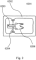
- FIG. 2 shows a packaging container (0201) including a casing (0202), a custom-shaped, multi-rooted, root-analogue dental implant (0208), together with two holders (0203), and a flat sheet material insert (0204).
- FIG. 3 shows a packaging container (0301) including a casing (0302), a custom-shaped, multi-rooted, root-analogue dental implant (0308) together with two holders (0305), and a flat sheet material insert (0304).
- FIG. 3 illustrates an embodiment of a casing in a three-dimensional (3D) view. This view also shows an example of inserts (0304), serving as connector between the holders (0305) and the casing (0302).
- an insert can be a single monolithic piece, such as a single piece of sheet metal, or the insert can be designed from multiple, connected pieces or parts.
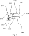
- FIG. 4 illustrates a pair of partially custom-shaped holders (0401, 0404), including an exemplary hinge design (0424), an upper indent or recess (0412) and a lower indent or recess disposed opposite to the upper indent or recess (not pictured) to indicate the area intended to be held by the fingers of a user.
- Custom-shaped holders (0401, 0404) further include a slot or a furrow (0408) to be received by a portion of a flat sheet material insert (e.g.
- Slots (0408) are shaped conforming to the dimensions of the inserts (e.g. 0104, 0304). It must be noted that the use of inserts can be avoided if the casing is equipped with mounting means so that the holders can be pushed directly into the casing.
- a degree of freedom when inserting the implant into a body cavity is the rotational orientation. Accordingly, it is preferable to mark at least one holder so that the rotational orientation of the implant is clearly indicated.
- holder (0401) bears a notch (0428) specifying the holder placed on the vestibular side of the implant.
- Custom shaped outer portions are shaped according to the crowns of the teeth being adjacent to the implant.
- the implant will be bordered at least on one side by another tooth (or a crown, bridge, or another implant), and when inserting the implant into the cavity with the help of the holders, the holders must not collide with the adjacent crowns or prosthetic components. Since the available space in the dentition is very limited, it may be required to shape the outer portions of the holders according to the adjacent crowns to avoid interferences.
- Custom shaped inner portions are conforming to the outer shape of the portion of the implant connecting to the abutment.
- the shape of the implant is designed with the help of a computer.
- the three-dimensional design data of the implant are then used to define portions (0419, 0420), for instance by using a holder design obtained from a library, providing excess material where the holders are gripping the implant, and using a software like the CAD software application called MAGICS (Materialise, Leuven, Belgium), for example, to remove the excess material by performing a Boolean operation, in this case a subtraction.
- virtual representations of custom shaped inner portions (0419, 0420) will be generated representing the exact negative of the implant, and thus be perfectly shaped to grip or clamp the implant.
- the virtual representation of the custom-shaped preparation post of the implant may be positively or negatively sized, or reduced or enlarged by CAD operations, at least partially, to account for manufacturing tolerances or shrinkage in the manufacturing process. The same may apply to the virtual representations of custom shaped inner portions (0419, 0420) of the holders.
- a next step the so-called “stitching" functionality of MAGICS may be used in case gaps are present in the resulting 3D surface.
- the outcome of this step is a virtual representation of a solid.
- a three-dimensional solid is an unambiguous numerical description of the surface of the geometrical shape of a three-dimensional object, with the numerical description showing no holes and clearly identifying the inside and the outside of the surface.
- the data derived from CAD operations in stereolithography (STL) data format is then converted, for example, to an initial graphics exchange specification (IGES), or similar, data format.
- IGES initial graphics exchange specification
- a piece of dental zirconia ceramic having a size of approximately 20 mm x 8 mm x 10 mm using a traditional 5-axis computer numerical control (CNC) milling device with a high-speed spindle (about 60,000 rpm), a spherical tungsten cutter having a diameter of the tip of the cutter of 1 mm and water cooling, can be used.
- CNC computer numerical control
- a spherical tungsten cutter having a diameter of the tip of the cutter of 1 mm and water cooling
- a first portion comprising the generic parts of the holder (the slot receiving the inserts, and the indent or recess intended to be held by the fingers of a user) is completed by grinding down layer-by-layer the workpiece to the shape of interest. Then the completed portion of the workpiece is clamped into a fixture.
- the customized portions of the surface are machined by grinding the workpiece down layer-by-layer to the desired shape. After properly cleaning, removing the excess, and degreasing, the workpiece is sintered and finished, the ceramic holder then being ready for use.
- Methods of fabricating holders, inserts, and the enclosing container include, but are not limited to, depositing, sintering, 3D printing, molding, curing, grinding, and milling.
- a layer-by-layer wax printing machine fabricates a three-dimensional wax representation (sample) from the three-dimensional design data.
- the sample is prepared and embedded for lost wax investment casting; the wax sample is burned out and the investment mold is filled with liquid precious metal (e.g., dental gold alloy).
- liquid precious metal e.g., dental gold alloy
- portions need to be customized only in case the corresponding portion of the implant is also customized. If that portion is generic, no customization is required. Different manufacturing technologies may be employed to fabricate the generic-shaped surfaces and to custom-shape the specific surfaces of the holder(s).
- FIG. 4 also shows hinge (0424), which serves as a bearing or support to ensure firm clamping of the implant.
- hinge (0424) serves as a bearing or support to ensure firm clamping of the implant.
- the gripping force will be distributed in a controlled manner to hinge (0424) and inner portions (0419, 0420), thus providing clamping force to hold a dental implant.
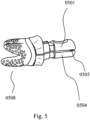
- FIG. 5 illustrates a pair of partially custom-shaped holders (0501, 0504) clamping a custom-shaped preparation post of a single-piece, custom-shaped, multi-rooted, root-analogue dental implant (0508), so that a hinge (0505), analogous to the hinge (0424) shown in the embodiment of FIG. 4 , and the fit of the inner custom shaped portions, analogous to (0419, 0420) according to the embodiment shown in FIG. 4 , matching the three-dimensional shape of the preparation post of the dental implant (0508), actually clamps the dental implant (0508) when operationally being gripped and held together by the operator, or alternatively a receiving element, as exemplarily shown in the embodiment of the flat sheet insert (e.g. 0104, 0304).
- a hinge 0505
- the fit of the inner custom shaped portions analogous to (0419, 0420) according to the embodiment shown in FIG. 4 , matching the three-dimensional shape of the preparation post of the dental implant (0508)
- a receiving element as
- the hinge which is, for example an extension of one holder placed in an indentation of the other holder, may restrict certain degrees of freedom in the relative movement between the two holders, so that the holders having a predefined position towards each other in order to increase the reliability of the clamping or gripping function of the prosthesis, when manually used.
- FIG. 6 shows a pair of holders (0601, 0604) where a pair of outer portions (0612), and a pair of inner portions (0608) are pre-fabricated to be further custom shaped.
- the design of the custom-shaped surfaces is derived as previously disclosed by using a CAD software like MAGICS, which allows material subtraction from the holders (0601, 0604) to customize the inner portions (0608), and to subtract the shape of the adjacent crowns to customize the outer portions (0612).
- the 3D shape of the adjacent crowns can be obtained using a variety of methods.
- imaging methods include, but are not limited to ultra sound, destructive scanning, active triangulation, passive triangulation, confocal scanning, and Time of Flight (TOF).
- TOF Time of Flight
- Such methods generate either surface descriptions, for example, in STL-format, or volumetric data, for example, in a so called “voxel"-format that can be transformed into surface data by generally available software applications known to those skilled in the art, and vice versa.
- the digital surface data consists of multiple measurement data points, each having an x, y, and z coordinate and together having a density better than 0.1 mm and an accuracy noise of less than 0.05 mm.
- Other resolutions, accuracies, and coordinate systems including, but not limited to cylindrical or spherical coordinate systems, can be employed by those skilled in the art.
- the data points are then exported in STL format according to this exemplary embodiment of the present invention.
- This widely used file format describes a surface or portions of a surface by interconnected triangles.
- STL files can be encoded either in binary or in ASCII format. Other established formats like PLY are also applicable.
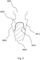
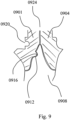
- FIGS. 7 , 8 , and 9 illustrate exemplary holders (0704, 0708, 0801, 0901, 0904) clamping exemplary custom-shaped preparation posts (surfaces 0728, 0732, 0816, 0912) of one-piece, single-rooted, root-analogue dental implants (0701, 0804, 0908).
- the surfaces of the implants' preparation posts and the corresponding custom shaped inner portions of the holders are showing additional slot and key features (e.g. 0916) providing undercuts. These undercuts provide an additional interlock, securing the implant safely to the holders even if the ensemble is held with moderate force.
- the custom-shaped preparation post of the dental implant is intended to receive a dental crown, and a custom-shaped portion of at least one of the holders includes an inverse or negative shape of a preparation post matching a corresponding surface of the preparation post of the dental implant.
- FIG. 7 also explains the mechanism of hinge (0716).
- the noticeable gap (0712, also shown as 0924 in FIG. 9 ) between holders (0704) and (0708) prevents contact between the holders (0704) and (0708), and they do not absorb any forces. Rather, when the holders are gripped at the recess, the gripping force will be supported only by hinge (0716), and by surfaces (0728) and (0732), which ensures a stable and reliable seating of the implant within the holders.
- FIG. 7 shows two slots or furrows (0720) and (0724). These slots serve as receptacles for inserts (0304 in FIG. 3 , and 1004 in FIG. 10 ), or can slide directly into guide rails (not pictured) of the casing.
- Guide rails of the casing could be designed to show a certain degree of elasticity, thus fixing the holders by frictional forces, or a movement of the holders in the rails could be prohibited by the closure of the casing, or a combination thereof.
- the guide rails can be designed so that they can be intentionally deformed by the user in order to release the frictional forces, thus allowing for easy removal of the holders and the prosthesis from the container.
- FIG. 9 also illustrates an embodiment of a mark or notch (0920) allowing the user to handle and insert the prosthesis correctly.
- the vestibular side of the dental implant is marked.
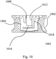
- FIG. 10 shows a packaging container (1001) including a casing (1002), and a flat-sheet material insert (1004) with a cut out, including corresponding surfaces (1008, 1012) to receive and hold in a closed position a pair of custom-shaped or generic-shaped holders.
- the insert of FIG. 10 comprises several grooves or cut-outs, generating a desired degree of flexibility or allowing for a certain degree of deformation.
- the holders are located between surfaces (1008) and (1012).
- Both edges show a certain amount of flexibility, resulting in an elastic grip of the ensemble of holders and implant.
- the long cut-out (1018) adjacent the leg (1016) located between the receptacles for the holders provides additional elasticity.
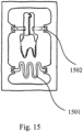
- the insert (1004) is shaped so that it fit into slots in the casing (1002). These slots can be seen in FIG. 15 (1502).
- the insert (1004) can slide freely inside the slots (1502).
- the outer top edges of the insert are manufactured to produce a press fit, so that the insert, once inserted into the casing, will be secured in place.
- the outer upper corners of the insert are bent slightly inwards with the help of a pair of pliers. This releases the grip force, and allows for forceless removal of the insert and the implant by gripping the implant at recesses (0412 in FIG. 4 ), and pulling slightly.
- the insert as exemplarily shown in FIG. 10 can be manufactured from sheet metal for example by laser or die cutting, water jet cutting, wire erosion, or other applicable processes.
- the insert is shaped in order to provide a large surface, and can serve as an additional getter surface.
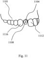
- FIG. 11 shows a custom-shaped preparation post of a dental implant (1104), having a vestibular notch or mark (1108), inserted in a position of a human dentition (1101) between two adjacent crowns (1112, 1116).
- the dental implant does not form part of the claimed invention
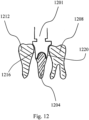
- FIG. 12 shows a root-form dental implant (1204) having a custom shaped preparation-post being held or clamped with a pair of partially custom-shaped holders (1201) during the insertion between two adjacent crowns (1208, 1212).
- the outer portions (1216) and (1220) of the holders are customized to conform to the corresponding surfaces of the adjacent crowns, providing a defined degree of freedom.
- the virtual shape(s) of the outer portions (1216) and (1220) can, for example, be derived by obtaining 3D data of the adjacent crowns, and by performing a Boolean operation (in this case a subtraction) in order to remove at least all portions from the virtual representation of the holders that would otherwise, when accordingly fabricated, interfere between the holders and the adjacent crowns.
- a Boolean operation in this case a subtraction
- the CAD software MAGICS also has functions allowing an orthogonal shift of the surface of an object by a specified amount. This allows reduction of a 3D body, and thus to create a small gap between the outer surface of the holder, and the outer surface of the crown, allowing for a certain degree of maneuverability.
- MAGICS has helpful features that have originally been developed to optimize plastic parts for injection molding, but also have been found to be useful for the processes of various embodiments of the present invention.
- the STL data describing the surfaces or solid representing the holder are then, for example, converted to an IGES data format.
- This is performed using, for example, software named SolidWorks (SolidWorks Corp., Concord, Mass. USA).
- the IGES file allows generating a CNC sequence to machine an artificial tooth from a piece of material like titanium or a titanium alloy (like Ti6Al4V), that consists, for example, of more than 60% of titanium.
- Ceramic material and other biocompatible materials or materials suitable for packaging medical devices including but not limited to stainless steel (like 1.4435, 1.4542 or 1.4548), synthetics, elastics, plastics, resin-modified glass-ionomer cement, hybrid-ionomer cement, resin-enforced cement, and other synthetic and plastic materials, are also applicable. Processes to manufacture solid parts based on digital 3D data are also described in the aforementioned '537 application.
- the holders are made from metal, and so-called rapid prototyping processes like selective laser melting are used to manufacture the holders.
- rapid prototyping processes like selective laser melting are used to manufacture the holders.
- a wide variety of materials and manufacturing processes are applicable to produce holders showing the required properties.
- the main requirements regarding holders and inserts are that they must withstand the processes used to ensure the purity of the implant, which may include sterilization and/or plasma cleaning.
- both the insert(s) and the holder(s) must maintain their shape during those processes.
- the holders are made from stabilized tetragonal zirconium oxide polycrystalline or another aluminum oxide or zirconium oxide material known to those skilled in the art (e.g. inCoris ZI, inCoris AL, VITABLOCS, and CEREC Blocs distributed by and Ivoclar Vivadent and SIRONA).
- the holders can be made of titanium or a titanium alloy and surface coated with zirconium oxide, for example, in sputtering technologies (as offered by Clinical House Europe GmbH).
- the packaging components are at least partially made of one of the following, or any combination of the following: titanium, titanium alloy that consists of more than about 60% of titanium, cement, zirconium oxide, ceramics, synthetics, elastics, plastics, stainless steel, glasiomer cement, resin-ionomer cement, hybrid-ionomer cement, resin-enforced cement, and acrylic based photopolymer.
- a rapid prototyping process is used for fabricating the holders and/or the packaging container and/or the inserts from hybrid materials.
- the rapid prototyping process may build the holder layer-by-layer. For example, a powdery layer of a substance can be applied on top of a workpiece, and then portions of the new layer are hardened by a controlled laser beam, while the other unhardened portions are later removed. In this manner, different substances having different properties (stiffness, hardness, biological properties etc.) can be applied, and therefore different portions of the workpiece are made from different materials.
- the portion of the holders enclosing the prosthesis is made from a material different from the one used for the generic portion with slot and recess.
- the holders, inserts or the container are an assembly of two or more parts.
- the parts are, for example, glued, sintered, mounted by pressure, and/or screwed to each other.
- the segments are fabricated using different materials and manufacturing technologies.
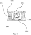
- FIG. 13 shows a cross-sectional view of a packaging container (1301) including a casing (1302) being hermetically sealed with a foil (1312), for example with a thickness of about 10 to about 1000 micrometers, e.g. about 50 micrometers, that is circumferentially welded (the welding seam indicated as 1316, also shown as 1420 in FIG. 14 ), having fixated a custom-shaped, multi-rooted, root-analogue dental implant (1308) in an insert (1304) made from flat sheet material.
- an air-tight closure of the packaging container is required in some embodiments.
- the functionality of the package has utmost priority, compared to cost savings.
- an exemplary embodiment comprises a disposable container.
- the outer shell of the container is made from only two pieces: the frame-like casing (1302) comprising the walls of the container and the bottom portion, and foil (1312) forming the seal of the container.
- the foil is laser-welded to the container.
- a circumferential weld seam ensures hermetical closure.
- the laser source is a fiber laser, emitting light at a wavelength of about 1070 nm.
- the laser beam is focused by optic components to a spot size of about 50 micrometers.
- the travel path of the laser light spot is numerically controlled by a two-axis or three-axis mirror system. Also, other laser technologies are readily available.
- Another option is a design where the bottom closure is not a part of the frame, but consists of another foil, which is welded to the frame using the same mechanism as for the upper closure.
- Yet another example would be to use a container fabricated by deep-drawing instead of milling. Further variants like selective laser melting have been mentioned with respect to FIG. 1 .
- this portion instead of welding a foil to the frame-like casing (1302), another option is to use this portion as a mechanical fixture for the prosthesis only, and to enclose this fixture by one or more foils that would be welded to each other.
- the packaging container could also be made from a tubular material, having for example a circular or rectangular cross section, and both openings on the ends of the pipe would be closed by foils.
- a foil made from synthetic material is used, having a thin metallic coating, and the container is sealed by heating and welding the plastic material.
- the examples listed above are reflecting only a fraction of processes and materials suitable for producing the packaging container. Accordingly, other methods of providing an air-tight enclosure can be selected. Welding, border crimping, and soldering, if executed properly, will produce excellent results, but other methods like bonding, vacuum sealing, or using a detachable connection can also serve for creating an airtight enclosure.
- Foils having an appropriate thickness can also be connected by hemming and/or creasing.
- Such a seam may not be as tight as a welded seam, but since the great majority of prostheses are fully customized for treatment of a specific patient, the product will be delivered in a short time frame, and will not reside inside the package for more than a couple of days.
- the packaging container can for instance be filled with helium. Helium molecules escaping from the container can easily be detected using a common leakage helium sniffer. Other gases and detection mechanisms are also applicable.
- the packaging container is for instance formed from a stable frame being enclosed by sealed foils, only the foils are dispensable, whereas the frame would be reused.
- This concept is also suitable for a tubular container as mentioned above. If a foil is welded directly to a solid frame-like structure, this structure can also be reused a couple of times by milling or grinding off the top layer, thus removing the residuals of the welding seam. If the container is initially fabricated with excess height, this refitting can be performed multiple times.
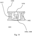
- FIG. 14 shows a cross-sectional view of a packaging container (1401) including a casing (1402) having a pair of holders (1404, 1408) in the receiving portion of the flat sheet material insert (1412) fixating the custom-shaped, multi-rooted, root-analogue dental implant.
- FIG. 15 is a top view of a packaging container having fixated a custom-shaped, multi-rooted, root-analogue dental implant and having an additional meandering-shaped flat sheet material (1501) that serves as an additional getter surface.
- a packaging container having fixated a custom-shaped, multi-rooted, root-analogue dental implant and having an additional meandering-shaped flat sheet material (1501) that serves as an additional getter surface.
- FIG. 16 shows a packaging container having fixated a custom-shaped, multi-rooted, root-analogue dental implant, and having one or more, in an exemplary embodiment two, LEDs (1601) radiating UVA, UVB, and/or UVC light (1604), for example in the range of a wavelength of about 230 to about 400 nm, e.g. about 250 nm.
- the LEDs can be permanently connected to a source of electricity, which would require attaching small batteries to the package, or they can be connected to a power source prior to the implantation process, for example by means of at least one isolating lead through into the encasement.
- the energy is transmitted by an inductive process into the encasement.
- the ultraviolet light is of advantage for disinfection processes, catalytic processes and/or for photo activation, which is a local charge shifting effect, for example, to enhance surfaces of the prosthesis for hard- and /or soft-tissue integration.
- Another option to expose the packed implant to UV radiation for removal of impurities is to manufacture portions of the packaging container from quartz glass, allowing for the passage of UV rays to the dental implant through the packaging container (not illustrated in the drawings).
- the packaging container would be placed into a small cradle comprising UV radiating elements, the elements being configured to match the quartz glass portions of the container.
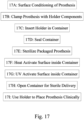
- FIG. 17 lists process steps that may be executed, sequentially or otherwise, in an exemplary embodiment, including surface conditioning of a prosthesis (step 17A), placing a prosthesis clamped in holder components in a packaging container (step 17B, step 17C), sealing the packaging container (step 17D), sterilizing (step 17E) and heat activating (step 17F) and/or UV activating (step 17G) of the prosthesis surfaces, opening the container for sterile delivery (step 17H), and using the holder to place the prosthesis clinically (step 171).
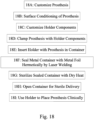
- FIG. 18 lists process steps that may be executed, sequentially or otherwise, in another exemplary embodiment, including: customizing a prosthesis (step 18A), applying a surface conditioning (step 18B), customizing holder components (step 18C), clamping the prosthesis with the holder components (step 18D), inserting the holder with the prosthesis in a metal container (step 18E), sealing the metal container with a metal foil hermetically by laser welding (step 18F), sterilizing the prosthesis inside the sealed container with dry heat (step 18G), or alternatively sterilizing the prosthesis inside the sealed container with beta, gamma or e-beam radiation, opening the container for sterile delivery of the prosthesis (step 18H) and using holder to place the prosthesis clinically (step 181).
- All process steps may be carried out by different and independent parties.
- the 3D acquisition of the shape of adjacent crowns for example, be performed at the dentist's office, at a hospital or at a location specialized in imaging.
- the imaging data can then be transferred to a location where the imaging data are further processed in order to ready them for manufacturing. Then, the data can be transferred to a remote manufacturing location. All of these data transfers can, for example, be performed via the Internet, using preferably Virtual Private Network channels to secure privacy, or through a local area network.
- FIG. 19 provides a brief overview of a system for laser welding, including a laser source (1901), an actuator-controlled two-axis or three-axis mirror system (1904) directing the beam (1908), a tool base (1916) to hold a container (1924), and a foil (1920) in very close proximity to container (1924).
- the fixture of container (1924) is spring loaded to avoid gaps between container (1924) and foil (1920).
- the fixture comprises a base (1940), a spring (1932), a swivel (1936), and a support (1928). This design allows the container to adjust in two rotational degrees of freedom, and distributes the forces induced by the spring to fixate and hold close against frame (1912) and tool base (1916), independent of thickness variances of container and/or foil.
- the spring (1932) is configured to apply, for example, a force in the range of about 1 to about 500 N, e.g. about 50 N to press the foil against the container.
- the allowable gap between the container surface and the foil for laser welding is, for example, in the range from direct contact to up to about 100 micrometers, so that the requirement for the evenness of the container, for example needs to be better than about 100 micrometers, e.g. up to about 10 micrometers.
- the mechanism(s) to open and load the fixture and to apply the spring forces are generally known to one skilled in the art.
- a system including one or more mirrors to direct the laser beam (“remote laser cutting") has several advantages over a system with a fixed beam where the container would be moved.
- the shape of the welding seam is specified by numerical data being fed into the system ("numerical control"). From the numerical data defining the welding path, the system calculates the required movements of the mirror(s). In this manner, curved seams can easily be achieved, just as well as a seam composed only from straight portions.
- Other systems may comprise a flexible fiber to transmit the laser energy to the welding spot. Additionally, after the welding process, the laser can be used to trim or cut off foil excess adjacent to the welding stream.
- the laser configuration of FIG. 19 is used to add labelling and/or tagging by marking and/or inscription onto the encasement surfaces.
- different laser energies or intensities are used to change surface color, for example, on materials that include titanium.
- FIGS. 20a and 20b illustrate a further improvement in positioning the foil and the container in close proximity for the welding process.
- frame (2016) is equipped with a number of springs (2012) being formed from short sections of elastic wire, and being mounted between frame (2016) and bracing (2020).
- the springs are located around the complete circumference of the container, and apply forces that safely press the foil against the container, regardless of minimal variances in the dimensions of container and foil.
- the springs are configured and arranged so that forces are applied every 500 micrometers adjacent the welding seam, and the springs are comb-like extensions to the bracing (2020), or directly integrated in the frame (2016).
- the individual springs (2012) or the comb-like prongs are configured to have, for example, an elasticity of up to about 1 mm, e.g. about 300 micrometers and to apply, each, a force, for example of up to 10 N, e.g. 1 N.
- a method comprises the steps of (a) placing a prosthesis in a metal encasement, (b) desorbing the metal components of the encasement, with or without the prosthesis, in a high vacuum chamber, the vacuum, for example in the range of about 10 -7 to 10 mbar, e.g. about 10 -6 mbar, with or without a heating process, for example in the range of about 20 °C to about 400 °C, e.g. about 300 °C, and (c) hermetically sealing the metal encasement, including the prosthesis.
- the aforementioned steps (a) and (b) are performed in reverse order.
- FIGS. 1 to 10 and 13 to 16 are also described as assemblies when put together in any configuration, in whole or in any partial configuration.
- a tear strip can be incorporated by deliberately weakening the material at predefined locations by, for example, a line of scoring.
- This line of scoring or groove can, for example, be applied by stamping, or by directing the laser beam used for welding at the location of the tear strip, and by reducing the power, and/or increasing the speed of movement of the beam, so that the material is engraved but not cut apart.
- a system of providing a prosthesis for sterile delivery comprises a prosthesis, and a holder the prosthesis including a first custom-shaped portion, the holder including a second custom-shaped portion, the first custom-shaped portion and the second custom-shaped portion provide a form-locking interface, so that, when the prosthesis is operationally positioned in the holder, the holder fixates the prosthesis by means of the form-locking fit in a pre-defined position and orientation with respect to the orientation and position of the holder.
- a system of packaging a prosthesis comprises a prosthesis and a covering, the covering encloses and seals hermetically the prosthesis, the prosthesis is sterile and the materials the covering is made of does not include any organic materials.
- the covering is for example made of metal.
- the covering is for example made titanium or a titanium alloy.
- a method comprises the steps of hermetically sealing a prosthesis, whether customized or not, in a covering, sterilizing the prosthesis inside the hermetically sealed covering, for example, by at least one of the following sterilization methods: exposure to dry heat, exposure to gamma radiation, exposure to beta radiation, exposure to high-energy ultraviolet light and exposure e-beam radiation, and performing a process to break up hydrocarbons, for example, by at least one of the following mechanisms: a catalytic reaction activated by heat, and photon triggered reaction activated by ultraviolet light.
- the catalytic reaction can be caused, for example, by one of the following materials: titanium, titanium alloys, titanium oxides zirconia, other metal oxides, and platinum.
- the term "catalytic reaction” includes a pyrolytic reaction, oxidative reaction, and/or reductive reaction.
- a hermetically sealed encasement that includes the prosthesis is filled, for example, with at least one of the following: environmental air, inert gas, oxygen, ammoniac, reactive gas mixtures, water (gas), hydrogen peroxide (gas), composed air, and purified air, at any pressure to include increased pressure, pressure of about 1 atmosphere, and vacuum.
- Electrodes are placed inside the encasement, for example, the prosthesis and/or the at least a portion of the encasement function(s) as electrode(s).
- the electric energy is conducted to at least one electrode by an isolating lead through into the encasement or an inductive process. With that, a plasma or corona discharge process may be performed that applies a coating onto a surface of the prosthesis inside the hermetically sealed encasement.
- CAD computer aided design
- CAM shall include, but shall not be limited to, any and all technology of computer aided manufacturing.
- CNC shall include, but shall not be limited to, any and all technology of computer numerical control as it relates to manufacturing machinery and systems, including but not limited to rapid prototyping devices and systems.
- Rapid prototyping shall include, but shall not be limited to, technologies qualified for manufacturing of copies of virtual three-dimensional objects and also technologies qualified for mass customization or the mass production of copies of customized or adapted geometries to the needs of an individual patient. Rapid prototyping in this context shall include, but not be limited to, manufacturing technologies based on the digital data, by a process that includes depositing material, in accordance with the digital data, layer-by-layer in a plurality of layers each constituting a two-dimensional cross section of a solid object having an edge defined by data of the three-dimensional surface, the layers being stacked in a third dimension to form the solid object having a three-dimensional surface defined by the data.
- Such rapid prototyping technologies can be directed to actually manufacturing the part of interest, for example, by selective laser sintering or indirect by fabricating first e.g., a resin or wax sample of the part of interest, and second using, for example, "lost-wax" casing to duplicate such sample and fabricate therewith the part of interest. It also includes sintering techniques where the "green" body is printed in response to computerized numerical controlled (CNC) data and sintered it to its final material properties. Sintering in this context includes pressure and heat.
- CNC computerized numerical controlled
- prosthesis shall include any substantially artificially shaped part of any natural and artificial material.
- 3D shall mean three-dimensional.
- imaging shall include, but shall not be limited to, any and all technology of acquiring two-dimensional and/or three-dimensional data of physical objects or parts of a human body.
- imaging data shall include, but shall not be limited to, invivo and in-vitro processes that result in any anatomical data of the anatomy of a human being.
- data shall include, but shall not be limited to, two-dimensional and three-dimensional data.
- three-dimensional data shall include, but shall not be limited to, surface (e.g. triangulated data) and volumetric (e.g. voxel) data.
Landscapes
- Health & Medical Sciences (AREA)
- Engineering & Computer Science (AREA)
- Life Sciences & Earth Sciences (AREA)
- Animal Behavior & Ethology (AREA)
- General Health & Medical Sciences (AREA)
- Public Health (AREA)
- Veterinary Medicine (AREA)
- Mechanical Engineering (AREA)
- Epidemiology (AREA)
- Oral & Maxillofacial Surgery (AREA)
- Dentistry (AREA)
- Orthopedic Medicine & Surgery (AREA)
- Biomedical Technology (AREA)
- Heart & Thoracic Surgery (AREA)
- Vascular Medicine (AREA)
- Transplantation (AREA)
- Cardiology (AREA)
- Plasma & Fusion (AREA)
- Physics & Mathematics (AREA)
- Chemical Kinetics & Catalysis (AREA)
- Chemical & Material Sciences (AREA)
- Dental Prosthetics (AREA)
- Prostheses (AREA)
- Architecture (AREA)
- Software Systems (AREA)
- Dental Tools And Instruments Or Auxiliary Dental Instruments (AREA)
Claims (9)
- Verfahren zum Designen und Herstellen einer Halterung (0103, 0203, 0305, 0401, 0404, 0501, 0504, 0704, 0708, 0801, 0901, 0904, 1201, 1404, 1408), wobei die Halterung funktionell ist, um ein individuell gefertigtes Zahnimplantat (0108, 0208, 0308, 0508, 0701, 0804, 0908, 1204, 1308) zu fixieren, wobei das individuell gefertigte Zahnimplantat einen mindestens teilweise individuell geformten Präparationspfosten (0728, 0732, 0816, 0912, 1104, 1108) zur Aufnahme einer Zahnkrone umfasst und eine Oberfläche des Präparationspfostens ein individuell geformter Anteil des Zahnimplantats ist, wobei das Verfahren die Schritte umfasst:Empfangen eines ersten Formdatensatzes, der die dreidimensionale Form des individuell geformten Anteils des Zahnimplantats repräsentiert;Ableiten eines ersten Herstellungsdatensatzes einer ersten virtuellen individuellen Form aus dem ersten Formdatensatz; undFormen von mindestens einem ersten individuell geformten Anteil (0419, 0420, 0916) der Halterung, der den individuell geformten Anteil des Zahnimplantats greift, in Reaktion auf den ersten Herstellungsdatensatz,wobei der Verfahrensschritt des Formens des mindestens einen individuell geformten Anteils der Halterung eine Rapid-Prototyping-Technologie nutzt, undwobei der mindestens eine erste individuell geformte Anteil der Halterung mindestens teilweise eine inverse Form des Präparationspfostens einschließt, die im Wesentlichen zu einem entsprechenden Anteil des individuell geformten Anteils des Präparationspfostens des Zahnimplantats passt.
- Verfahren nach Anspruch 1, wobei der Verfahrensschritt des Ableitens des ersten Herstellungsdatensatzes einen Boole'schen Algorithmus nutzt.
- Verfahren nach einem der vorhergehenden Ansprüche, wobei der Verfahrensschritt des Formens eine nummerisch gesteuerte Frästechnologie nutzt.
- Verfahren nach einem der vorhergehenden Ansprüche, wobei die Halterung aus Zirconiumdioxid gefertigt ist, und wobei das Verfahren des Weiteren den Schritt des Sinterns der Halterung umfasst.
- Verfahren nach einem der vorhergehenden Ansprüche, wobei das individuell gefertigte Zahnimplantat funktionell ist, um einen vorab identifizierten Zahn eines spezifischen Patienten zu ersetzen, und wobei das Verfahren des Weiteren die Schritte umfasst: Empfangen eines zweiten Formdatensatzes, der eine dreidimensionale Form einer Krone (1208, 1212) eines Zahns repräsentiert, der benachbart zu dem vorab identifizierten Zahn ist, der durch das individuell gefertigte Zahnimplantat ersetzt werden soll; Ableiten eines zweiten Herstellungsdatensatzes einer zweiten virtuellen individuellen Form aus dem zweiten Datensatz; und Formen von mindestens einem zweiten individuell geformten Anteil (1216, 1220) der Halterung in Reaktion auf den zweiten Herstellungsdatensatz.
- Verfahren nach einem der vorhergehenden Ansprüche, wobei die Rapid-Prototyping-Technologie Hochgeschwindigkeitsfräsen oder Hochgeschwindigkeitsschleifen einschließt.
- Verfahren nach einem der vorhergehenden Ansprüche, wobei die Rapid-Prototyping-Technologie Laserschmelzen einschließt.
- Verfahren nach einem der vorhergehenden Ansprüche, wobei die Rapid-Prototyping-Technologie die Halterung Schicht für Schicht aufbaut.
- Verfahren nach Anspruch 8, wobei der Rapid-Prototyping-Prozess Aufbringen einer pulverigen Schicht einer Substanz auf ein Werkstück und Härten von Anteilen der neuen Schicht durch einen gesteuerten Laserstrahl, während die anderen ungehärteten Anteile später entfernt werden, einschließt.
Applications Claiming Priority (4)
| Application Number | Priority Date | Filing Date | Title |
|---|---|---|---|
| US201562174895P | 2015-06-12 | 2015-06-12 | |
| US15/153,598 US11633270B2 (en) | 2015-06-12 | 2016-05-12 | Systems and methods for sterile delivery of prostheses |
| US15/153,595 US20160361150A1 (en) | 2015-06-12 | 2016-05-12 | Systems and methods for sterile delivery of prostheses |
| PCT/EP2016/062978 WO2016198429A1 (en) | 2015-06-12 | 2016-06-08 | Systems and methods for sterile delivery of prostheses |
Publications (3)
| Publication Number | Publication Date |
|---|---|
| EP3307201A1 EP3307201A1 (de) | 2018-04-18 |
| EP3307201C0 EP3307201C0 (de) | 2024-10-23 |
| EP3307201B1 true EP3307201B1 (de) | 2024-10-23 |
Family
ID=57515631
Family Applications (2)
| Application Number | Title | Priority Date | Filing Date |
|---|---|---|---|
| EP16738680.4A Withdrawn EP3307200A1 (de) | 2015-06-12 | 2016-06-08 | Systeme und verfahren zur sterilen einführung einer prothese |
| EP16741539.7A Active EP3307201B1 (de) | 2015-06-12 | 2016-06-08 | Verfahren zum designen und zur herstellung einer halterung |
Family Applications Before (1)
| Application Number | Title | Priority Date | Filing Date |
|---|---|---|---|
| EP16738680.4A Withdrawn EP3307200A1 (de) | 2015-06-12 | 2016-06-08 | Systeme und verfahren zur sterilen einführung einer prothese |
Country Status (2)
| Country | Link |
|---|---|
| US (2) | US11633270B2 (de) |
| EP (2) | EP3307200A1 (de) |
Families Citing this family (9)
| Publication number | Priority date | Publication date | Assignee | Title |
|---|---|---|---|---|
| TW201808233A (zh) * | 2016-06-02 | 2018-03-16 | 康洛格生物科技公司 | 保持器、包裝與保持器之組合體、手術裝置用轉接器及具有支撐結構的手術裝置用保持器 |
| EP3335666B1 (de) * | 2016-12-15 | 2021-03-10 | Ivoclar Vivadent AG | Vorrichtung zum halten einer anordnung aus suprastruktur und abutment |
| KR102047451B1 (ko) * | 2017-09-15 | 2019-12-02 | 주식회사 디오 | 치아 임플란트용 포장용기 |
| WO2020045824A1 (ko) * | 2018-08-28 | 2020-03-05 | 주식회사 디오 | 치아 임플란트용 포장용기 |
| USD933846S1 (en) * | 2019-12-24 | 2021-10-19 | PrinterPrezz, Inc. | Medical sterilization device |
| US11878086B2 (en) * | 2020-04-15 | 2024-01-23 | Honeywell International Inc. | Apparatuses and methods for improved sanitization |
| US20220047741A1 (en) * | 2020-08-14 | 2022-02-17 | J.H. Technologies, Inc. | Apparatus and system for ultraviolet light sanitization of microscope eyepieces and method therefor |
| US11484396B1 (en) | 2021-06-21 | 2022-11-01 | Identical, Inc. | Root-analog dental implants and systems, devices, and methods for designing and manufacturing same |
| KR102740159B1 (ko) * | 2024-04-25 | 2024-12-10 | 주식회사 덴트바이오 | 파우치와 일체로 구성된 가변형 인상트레이 |
Citations (1)
| Publication number | Priority date | Publication date | Assignee | Title |
|---|---|---|---|---|
| US20130209961A1 (en) * | 2011-03-18 | 2013-08-15 | Natural Dental Implants Ag | Dental Implant Assembly, Implant, and Prosthesis to Replace a Nonfunctional Natural Tooth and Related Methods |
Family Cites Families (25)
| Publication number | Priority date | Publication date | Assignee | Title |
|---|---|---|---|---|
| US4585453A (en) * | 1983-02-22 | 1986-04-29 | Shiley, Incorporated | Disposable holder for prosthetic heart valve |
| US4614008A (en) * | 1985-09-19 | 1986-09-30 | Fred Brill | Spring biased clothes pin |
| US4801015A (en) * | 1986-04-16 | 1989-01-31 | Shiley Inc. | Releasable holder and package assembly for a prosthetic heart valve |
| CH674223A5 (de) * | 1987-12-16 | 1990-05-15 | Hugo Ledermann | |
| US5197878A (en) * | 1990-10-23 | 1993-03-30 | Thomas A. Lukase | Clamp for removing a dental prosthetic |
| US5236450A (en) * | 1992-06-04 | 1993-08-17 | Carbon Implants, Inc. | Heart valve holder-rotator |
| US5538129A (en) * | 1995-03-21 | 1996-07-23 | Minnesota Mining And Manufacturing Company | Package for adhesive precoated dental appliance |
| US5720391A (en) * | 1996-03-29 | 1998-02-24 | St. Jude Medical, Inc. | Packaging and holder for heart valve prosthesis |
| EP1023910A1 (de) | 1999-01-29 | 2000-08-02 | Institut Straumann AG | Herstellung von osteophilen Oberflächen im Knochen verankerbarer metallischer Prothesen |
| DE10065788A1 (de) * | 2000-12-22 | 2002-07-11 | Poly An Ges Zur Herstellung Vo | Oberflächenfunktionalisiertes Trägermaterial, Verfahren für seine Herstellung sowie Festphasensyntheseverfahren |
| DE10305948A1 (de) | 2003-02-12 | 2004-09-02 | Heraeus Kulzer Gmbh & Co. Kg | Verpackung für ein Dentalimplantat |
| US20070095698A1 (en) * | 2005-10-14 | 2007-05-03 | Cambron Ronald E | Apparatus for storing biological prostheses |
| US7451870B2 (en) | 2006-02-06 | 2008-11-18 | Zimmer Dental, Inc. | Medical implant package with a cap having a cavity |
| US20070209957A1 (en) | 2006-03-09 | 2007-09-13 | Sdgi Holdings, Inc. | Packaging system for medical devices |
| US8602780B2 (en) | 2006-10-16 | 2013-12-10 | Natural Dental Implants, Ag | Customized dental prosthesis for periodontal or osseointegration and related systems and methods |
| KR101495886B1 (ko) | 2007-07-19 | 2015-02-26 | 한국전자통신연구원 | 하향링크 프레임 생성 방법 및 셀 탐색 방법 |
| WO2009019770A1 (ja) | 2007-08-08 | 2009-02-12 | Kabushiki Kaisha Shofu | ブリスター状人工歯包装容器 |
| KR100982967B1 (ko) | 2008-09-24 | 2010-09-17 | 오스템임플란트 주식회사 | 임플란트 픽스츄어 고정용 그립 |
| ITFI20080224A1 (it) | 2008-11-18 | 2010-05-19 | Giovanni Baldi | Dispositivo per la sterilizzazione di viti e/o protesi dentali |
| EP2281527A1 (de) * | 2009-07-27 | 2011-02-09 | Straumann Holding AG | Adapter zum Übertragen eines Drehmoments auf den Aufbauteil eines Dentalimplantats |
| WO2011113568A1 (en) | 2010-03-15 | 2011-09-22 | Nobel Biocare Services Ag | Surface treatment method |
| DE102011101678A1 (de) * | 2011-05-16 | 2012-11-22 | Amann Girrbach Ag | Prothesenzahnträger |
| KR101283490B1 (ko) | 2011-09-09 | 2013-07-12 | 오스템임플란트 주식회사 | 습도유지 가능한 임플란트 보관용 앰플 |
| ES2526883T3 (es) * | 2012-05-08 | 2015-01-16 | Dentsply Ih Ab | Envase para brocas, método y disposición asociados |
| CN114007551B (zh) * | 2019-08-02 | 2025-10-17 | 爱德华兹生命科学公司 | 假体心脏瓣膜包装 |
-
2016
- 2016-05-12 US US15/153,598 patent/US11633270B2/en active Active
- 2016-05-12 US US15/153,595 patent/US20160361150A1/en not_active Abandoned
- 2016-06-08 EP EP16738680.4A patent/EP3307200A1/de not_active Withdrawn
- 2016-06-08 EP EP16741539.7A patent/EP3307201B1/de active Active
Patent Citations (1)
| Publication number | Priority date | Publication date | Assignee | Title |
|---|---|---|---|---|
| US20130209961A1 (en) * | 2011-03-18 | 2013-08-15 | Natural Dental Implants Ag | Dental Implant Assembly, Implant, and Prosthesis to Replace a Nonfunctional Natural Tooth and Related Methods |
Also Published As
| Publication number | Publication date |
|---|---|
| EP3307201C0 (de) | 2024-10-23 |
| EP3307201A1 (de) | 2018-04-18 |
| US20160361150A1 (en) | 2016-12-15 |
| EP3307200A1 (de) | 2018-04-18 |
| US11633270B2 (en) | 2023-04-25 |
| US20160361146A1 (en) | 2016-12-15 |
Similar Documents
| Publication | Publication Date | Title |
|---|---|---|
| EP3307201B1 (de) | Verfahren zum designen und zur herstellung einer halterung | |
| Schepers et al. | Fully 3‐dimensional digitally planned reconstruction of a mandible with a free vascularized fibula and immediate placement of an implant‐supported prosthetic construction | |
| WO2016198429A1 (en) | Systems and methods for sterile delivery of prostheses | |
| Song et al. | Accuracy on scanned images of full arch models with orthodontic brackets by various intraoral scanners in the presence of artificial saliva | |
| KR102332888B1 (ko) | 트랜스퍼 트레이의 제조 방법 | |
| US20080228303A1 (en) | Direct manufacture of dental and medical devices | |
| WO2018090579A2 (zh) | 一种同期行固定-活动联合修复方法 | |
| JP2019005599A (ja) | 歯科用補綴物を支持する歯支台の製造方法 | |
| Chandran et al. | Digital versus conventional impressions in dentistry: A systematic review. | |
| US20120237902A1 (en) | Techniques for providing custom-formed implants | |
| AlHelal et al. | A Protocol for Screw-Retrievable, Cement-Retained, Implant-Supported Fixed Partial Dentures. | |
| Sheela et al. | 3D printing in dental implants | |
| CN106456283A (zh) | 牙科修复装置及其使用方法 | |
| Punjabi et al. | Maxillary hollow-bulb obturator: A paradigm shift | |
| Vera et al. | Prosthetic reconstruction of a patient with an acquired nasal defect using extraoral implants and a CAD/CAM copy‐milled bar | |
| US20230293273A1 (en) | Systems and methods for sterile delivery of prostheses | |
| KR101832979B1 (ko) | 보철물 포장 케이스 | |
| Markarian et al. | Effect of different milling devices on marginal fit of cad-cam zirconia copings on implant stock abutments | |
| Jamshidi et al. | Marginal fit of endocrowns fabricated by three-dimensional printing and the conventional method: an in vitro study | |
| Önöral | Marginal discrepancy of 3-unit Co-Cr metal copings fabricated with additive and subtractive manners: A comparative study | |
| US10729517B2 (en) | Ascertaining the spatial positions and orientations of implants anchored in a jaw of a patient | |
| Lahori et al. | An evaluation of the accuracy of multiple implant impression techniques: an in vitro study | |
| Dubuc et al. | Opinions from five oral specialists on 3D printing in the challenge of customized oral healthcare. What can plasma technology bring? | |
| Wei et al. | Exploration of the application of digital technology in implant treatment of edentulous patients | |
| Bae et al. | Evaluation of internal fit of press ceramic and porous structured cobalt–chromium crown fabricated by additive manufacturing |
Legal Events
| Date | Code | Title | Description |
|---|---|---|---|
| STAA | Information on the status of an ep patent application or granted ep patent |
Free format text: STATUS: THE INTERNATIONAL PUBLICATION HAS BEEN MADE |
|
| PUAI | Public reference made under article 153(3) epc to a published international application that has entered the european phase |
Free format text: ORIGINAL CODE: 0009012 |
|
| STAA | Information on the status of an ep patent application or granted ep patent |
Free format text: STATUS: REQUEST FOR EXAMINATION WAS MADE |
|
| 17P | Request for examination filed |
Effective date: 20180109 |
|
| AK | Designated contracting states |
Kind code of ref document: A1 Designated state(s): AL AT BE BG CH CY CZ DE DK EE ES FI FR GB GR HR HU IE IS IT LI LT LU LV MC MK MT NL NO PL PT RO RS SE SI SK SM TR |
|
| AX | Request for extension of the european patent |
Extension state: BA ME |
|
| RIN1 | Information on inventor provided before grant (corrected) |
Inventor name: BERNDT, JONATHAN CORNELIUS Inventor name: WEINRICH, ANDREAS Inventor name: RUBBERT, RUEDGER Inventor name: SCHULZ, SABINE Inventor name: BERNDT, ERNST-ULRICH GERHARD |
|
| DAV | Request for validation of the european patent (deleted) | ||
| DAX | Request for extension of the european patent (deleted) | ||
| STAA | Information on the status of an ep patent application or granted ep patent |
Free format text: STATUS: EXAMINATION IS IN PROGRESS |
|
| 17Q | First examination report despatched |
Effective date: 20190812 |
|
| 19U | Interruption of proceedings before grant |
Effective date: 20191111 |
|
| 19W | Proceedings resumed before grant after interruption of proceedings |
Effective date: 20230201 |
|
| RAP3 | Party data changed (applicant data changed or rights of an application transferred) |
Owner name: RTRS INVESTMENT, LLC |
|
| GRAP | Despatch of communication of intention to grant a patent |
Free format text: ORIGINAL CODE: EPIDOSNIGR1 |
|
| STAA | Information on the status of an ep patent application or granted ep patent |
Free format text: STATUS: GRANT OF PATENT IS INTENDED |
|
| INTG | Intention to grant announced |
Effective date: 20240521 |
|
| GRAS | Grant fee paid |
Free format text: ORIGINAL CODE: EPIDOSNIGR3 |
|
| GRAA | (expected) grant |
Free format text: ORIGINAL CODE: 0009210 |
|
| STAA | Information on the status of an ep patent application or granted ep patent |
Free format text: STATUS: THE PATENT HAS BEEN GRANTED |
|
| AK | Designated contracting states |
Kind code of ref document: B1 Designated state(s): AL AT BE BG CH CY CZ DE DK EE ES FI FR GB GR HR HU IE IS IT LI LT LU LV MC MK MT NL NO PL PT RO RS SE SI SK SM TR |
|
| REG | Reference to a national code |
Ref country code: GB Ref legal event code: FG4D |
|
| REG | Reference to a national code |
Ref country code: CH Ref legal event code: EP |
|
| REG | Reference to a national code |
Ref country code: DE Ref legal event code: R096 Ref document number: 602016089938 Country of ref document: DE |
|
| REG | Reference to a national code |
Ref country code: IE Ref legal event code: FG4D |
|
| U01 | Request for unitary effect filed |
Effective date: 20241119 |
|
| U07 | Unitary effect registered |
Designated state(s): AT BE BG DE DK EE FI FR IT LT LU LV MT NL PT RO SE SI Effective date: 20241125 |
|
| PG25 | Lapsed in a contracting state [announced via postgrant information from national office to epo] |
Ref country code: IS Free format text: LAPSE BECAUSE OF FAILURE TO SUBMIT A TRANSLATION OF THE DESCRIPTION OR TO PAY THE FEE WITHIN THE PRESCRIBED TIME-LIMIT Effective date: 20250223 Ref country code: HR Free format text: LAPSE BECAUSE OF FAILURE TO SUBMIT A TRANSLATION OF THE DESCRIPTION OR TO PAY THE FEE WITHIN THE PRESCRIBED TIME-LIMIT Effective date: 20241023 |
|
| PG25 | Lapsed in a contracting state [announced via postgrant information from national office to epo] |
Ref country code: ES Free format text: LAPSE BECAUSE OF FAILURE TO SUBMIT A TRANSLATION OF THE DESCRIPTION OR TO PAY THE FEE WITHIN THE PRESCRIBED TIME-LIMIT Effective date: 20241023 |
|
| PG25 | Lapsed in a contracting state [announced via postgrant information from national office to epo] |
Ref country code: NO Free format text: LAPSE BECAUSE OF FAILURE TO SUBMIT A TRANSLATION OF THE DESCRIPTION OR TO PAY THE FEE WITHIN THE PRESCRIBED TIME-LIMIT Effective date: 20250123 |
|
| PG25 | Lapsed in a contracting state [announced via postgrant information from national office to epo] |
Ref country code: GR Free format text: LAPSE BECAUSE OF FAILURE TO SUBMIT A TRANSLATION OF THE DESCRIPTION OR TO PAY THE FEE WITHIN THE PRESCRIBED TIME-LIMIT Effective date: 20250124 |
|
| PG25 | Lapsed in a contracting state [announced via postgrant information from national office to epo] |
Ref country code: PL Free format text: LAPSE BECAUSE OF FAILURE TO SUBMIT A TRANSLATION OF THE DESCRIPTION OR TO PAY THE FEE WITHIN THE PRESCRIBED TIME-LIMIT Effective date: 20241023 |
|
| PG25 | Lapsed in a contracting state [announced via postgrant information from national office to epo] |
Ref country code: RS Free format text: LAPSE BECAUSE OF FAILURE TO SUBMIT A TRANSLATION OF THE DESCRIPTION OR TO PAY THE FEE WITHIN THE PRESCRIBED TIME-LIMIT Effective date: 20250123 |
|
| PG25 | Lapsed in a contracting state [announced via postgrant information from national office to epo] |
Ref country code: SM Free format text: LAPSE BECAUSE OF FAILURE TO SUBMIT A TRANSLATION OF THE DESCRIPTION OR TO PAY THE FEE WITHIN THE PRESCRIBED TIME-LIMIT Effective date: 20241023 |
|
| PG25 | Lapsed in a contracting state [announced via postgrant information from national office to epo] |
Ref country code: SK Free format text: LAPSE BECAUSE OF FAILURE TO SUBMIT A TRANSLATION OF THE DESCRIPTION OR TO PAY THE FEE WITHIN THE PRESCRIBED TIME-LIMIT Effective date: 20241023 |
|
| PG25 | Lapsed in a contracting state [announced via postgrant information from national office to epo] |
Ref country code: CZ Free format text: LAPSE BECAUSE OF FAILURE TO SUBMIT A TRANSLATION OF THE DESCRIPTION OR TO PAY THE FEE WITHIN THE PRESCRIBED TIME-LIMIT Effective date: 20241023 |
|
| U20 | Renewal fee for the european patent with unitary effect paid |
Year of fee payment: 10 Effective date: 20250627 |
|
| PLBE | No opposition filed within time limit |
Free format text: ORIGINAL CODE: 0009261 |
|
| STAA | Information on the status of an ep patent application or granted ep patent |
Free format text: STATUS: NO OPPOSITION FILED WITHIN TIME LIMIT |
|
| 26N | No opposition filed |
Effective date: 20250724 |