EP3307183B1 - Vorrichtung zur schädigung oder zerstörung von adipozyten - Google Patents
Vorrichtung zur schädigung oder zerstörung von adipozyten Download PDFInfo
- Publication number
- EP3307183B1 EP3307183B1 EP16812127.5A EP16812127A EP3307183B1 EP 3307183 B1 EP3307183 B1 EP 3307183B1 EP 16812127 A EP16812127 A EP 16812127A EP 3307183 B1 EP3307183 B1 EP 3307183B1
- Authority
- EP
- European Patent Office
- Prior art keywords
- skin
- patient
- semisphere
- probe
- ultrasound
- Prior art date
- Legal status (The legal status is an assumption and is not a legal conclusion. Google has not performed a legal analysis and makes no representation as to the accuracy of the status listed.)
- Active
Links
Images

Classifications
-
- A—HUMAN NECESSITIES
- A61—MEDICAL OR VETERINARY SCIENCE; HYGIENE
- A61N—ELECTROTHERAPY; MAGNETOTHERAPY; RADIATION THERAPY; ULTRASOUND THERAPY
- A61N7/00—Ultrasound therapy
-
- A—HUMAN NECESSITIES
- A61—MEDICAL OR VETERINARY SCIENCE; HYGIENE
- A61N—ELECTROTHERAPY; MAGNETOTHERAPY; RADIATION THERAPY; ULTRASOUND THERAPY
- A61N7/00—Ultrasound therapy
- A61N2007/0004—Applications of ultrasound therapy
- A61N2007/0008—Destruction of fat cells
Definitions
- This invention relates to an apparatus for applying transversal ultrasound waves to a patient's skin in order to damage and/or destroy adipocytes located under the dermis of the patient's skin.
- adipocytes Procedures currently exist for removing fat cells under the skin, whereby those fat cells or adipose cells are also commonly referred to as "adipocytes.”
- One such procedure ruptures adipocytes using longitudinal ultrasound waves, whereby ultrasound waves are applied to adipose tissue beneath the skin surface (the dermis).
- the ultrasound waves rupture the adipocytes in the adipose tissue under the skin surface, causing necrosis, which can cause extensive collateral damage to other non-fat tissue (e.g., blood vessels, connective tissue, dermis, etc.).
- Britva describes applying longitudinal ultrasound waves to a patient's skin during a hot mode of operation, and to apply transverse ultrasound waves to the patient's skin during a cold mode of operation, in order to enhance the destruction of adipocytes under the skin surface.
- Britva describes that adipocytes typically die within three days after treatment of a patient's skin with both transverse ultrasound waves and longitudinal ultrasound waves.
- Britva describes the use of two resonant frequencies: a) a cold mode resonant frequency of about 69 kHz, and b) a hot mode resonant frequency of about 60 kHz.
- Britva's sonotrobe applies ultrasound vibrations in the distal portion of his sonotrobe primarily in a direction substantially perpendicular to the elongate neck axis (e.g., the longitudinal axis) of the sonotrobe, and whereby a transverse mechanical standing wave is generated in the distal portion of his sonotrobe by way of ridges that convert longitudinal waves to transverse waves, for application to the patient's skin.
- Britva's sonotrobe applies ultrasound vibrations in the distal portion of his sonotrobe primarily in a direction substantially parallel to the elongate neck axis of the sonotrobe, and whereby a longitudinal mechanical standing wave is generated in the distal portion of his sonotrobe.
- Britva's ultrasound generator housed within a proximal part of his sonotrobe only outputs longitudinal waves, for which some of those waves are converted to transverse waves by way of the complex structure of his distal curved portion with plural ridges or undulations (as shown in Figures 9A-9C of Britva).
- the apparatus includes a main body portion that houses an ultrasound transducer, in which the main body portion is provided at a proximal end of the apparatus furthest from the patient's skin when the patient is being treated with the apparatus.
- the apparatus further includes a semisphere portion provided at a distal end of the apparatus and that is configured to contact the patient's skin when the patient is being treated with the apparatus.
- the apparatus further includes an intermediate portion provided between the main body portion and the semisphere portion, in which the intermediate portion is disposed substantially perpendicular to the main body portion such that a main axis of the main body portion is provided along a first plane substantially parallel to a second plane corresponding to a surface of the patient's skin being treated with the apparatus, and such that a main axis of the intermediate portion is provided along a third plane substantially perpendicular to the second plane.
- the ultrasound transducer is configured to vibrate along the first plane and to thereby cause the semisphere portion to vibrate substantially parallel to the patient's skin due to a connector provided within the intermediate portion that connects the ultrasound transducer to the semisphere. This results in transverse ultrasound waves being applied to the patient's skin by way of the apparatus, which results in destruction and/or damage to adipocytes located beneath a dermis of the patient's skin.
- the method includes outputting transverse ultrasound vibrations from an ultrasound transducer provided in a proximal end of the probe to a first end of a connecting rod.
- the method also includes providing the transverse ultrasound vibrations from the first end of the connecting rod to a second end of the connecting rod that is connected to a semisphere portion located at a distal end of the probe.
- the transverse ultrasound vibrations are configured to be applied to the patient's skin by contacting the semisphere portion of the probe to the patient's skin.
- the present specification is directed to an apparatus and method for applying transversal ultrasound waves to a patient's skin in order to damage and/or destroy adipocytes located under the dermis of the patient's skin.
- a probe provides transverse ultrasound vibrations to a patient's skin, whereby those transverse ultrasound vibrations impinge on the skin surface substantially parallel to the skin surface, and enter into the skin surface a predetermined depth, such as 20 - 40 mm before being substantially attenuated, so as to damage and/or destroy adipose cells within a certain range (e.g., 0.01 to 40 mm) under the skin surface.
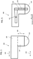
- Fig. 1 shows a probe 100 according to one or more embodiments of the invention.
- a distal end of the probe 100 includes a semisphere portion 110, whereby the semisphere portion 110 receives transverse ultrasound vibrations output from an ultrasound transducer 120, provided in a main body portion 105 of the probe 100 (that is provided at a proximal end of the probe 100).
- a metal component also referred herein as a connector rod 130, is provided within an intermediate portion 107 of the probe 100, whereby the connector rod 130 transfers transverse ultrasound vibrations output from the ultrasound transducer 120 directly to the semisphere portion 110 of the probe, for application of those transverse ultrasound vibrations to the patient's skin.
- the semisphere portion 110 of the probe 100 has a radius of 20 mm, so that transverse ultrasound vibrations are applied to a depth of 20 mm by way of pressing the semisphere portion of the probe 100 against the patient's skin during treatment of the patient's skin to damage and/or destroy adipose cells underneath the patient's skin.
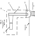
- FIG. 4 shows the probe 100 according to an embodiment being pressed against the patient's skin 400, so that the semisphere portion 110 of the probe 100 is positioned 20 mm inward with respect to upper surfaces of the skin that are adjacent to but not in direct contact with the semisphere portion 110 of the probe 100.
- FIG. 4 shows the probe 100 according to an embodiment being pressed against the patient's skin 400, so that the semisphere portion 110 of the probe 100 is positioned 20 mm inward with respect to upper surfaces of the skin that are adjacent to but not in direct contact with the semisphere portion 110 of the probe 100.
- the housing of the probe 100 is shown by way of the dashed line region 410, whereby the components within the housing of the probe 100 that create the transverse ultrasound vibrations and provide those vibrations to the skin 400 are shown by way of the ultrasound transducer 120 and the connector rod 130. Also, the direction of transverse vibrations applied to be applied to the patient's skin 410 are shown by way of double-ended arrows 430.
- the strength of the transverse ultrasound vibrations is strong enough such that adipose cells located within a range up to 40 mm beneath the patient's skin are damaged and/or destroyed when subjected to those transverse ultrasound vibrations.
- a semisphere portion having a smooth outer surface at a distal end of the probe whereby no ridges or undulations are provided on the outer surface of the semisphere portion (in contrast to the structure of Britva)
- a smoother treatment effect can be obtained, whereby the semisphere portion can easily glide over a portion of the patient's skin to be treated to damage and/or destroy adipose cells located beneath that portion of the patient's skin.
- the probe 100 of FIG. 1 includes a main body portion 105 that houses an ultrasound transducer 120 as seen in Fig. 5 , in which the main body portion 105 is provided at a proximal end of the probe 100 furthest from the patient's skin when the patient is being treated with the probe 100.
- the probe 100 further includes a semisphere portion 110 provided at a distal end of the probe 100 that is configured to contact the patient's skin when the patient is being treated with the probe 100.
- the probe 100 further includes an intermediate portion 107 provided between the main body portion 105 and the semisphere portion 110, in which the intermediate portion 107 is disposed substantially perpendicular to the main body portion 105 such that a main axis of the main body portion 105 is provided along a first plane 140 substantially parallel to a second plane 150 corresponding to a surface of the patient's skin being treated with the probe 100, and such that a main axis of the intermediate portion 107 is provided along a third plane 160 substantially perpendicular to the second plane.
- the ultrasound transducer is configured to vibrate along the first plane 140 and to thereby cause the semisphere portion 110 to vibrate substantially parallel to the patient's skin due to a connector provided within the intermediate portion that connects the ultrasound transducer to the semisphere. This results in transverse ultrasound waves being applied to the patient's skin by way of the probe 100, which results in destruction and/or damage to adipocytes located beneath a dermis of the patient's skin.
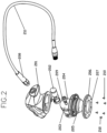
- FIG. 2 shows in exploded view various components that may be utilized to create a probe 100 according to one or more embodiments. Those components include:
- FIG. 3 shows details of an ultrasound transducer 120 that can be provided within the main body portion 105 of the probe 100, according to one or more embodiments.
- the ultrasound transducer 120 may be constructed as a piezoelectric device or other type of device that provides ultrasound vibrations. In some configurations, two piezoelectric plates are coupled to each other, with one plate causing a vibration in an opposite direction with respect to the other plate.
- the ultrasound transducer (having a total length of 57 mm, a minimum width of 38 mm, and a maximum width of 48 mm) includes:
- the ultrasound transducer 120 is housed in the main body portion 105 of the probe 100, which has a main axis 140 that is substantially parallel to the patient's skin to be treated by the probe. With such a construction, the ultrasound transducer 120 outputs vibrations that are substantially parallel to the patient's skin, and thus are transverse ultrasound vibrations.
- the transverse ultrasound vibrations output from the ultrasound transducer are transferred to the semisphere portion of the probe by way of a metal plate, or connector rod 130, as shown in FIG. 5 .
- the connector rod 130 may be configured as having one main axis 510, and thus corresponding to a long rod-shaped structure.
- the connector rod 130 may be of an aluminum construction (e.g., an aluminum plate) or of another lightweight metal construction.
- One end of the connector rod 130 is in direct contact to the ultrasound transducer 120 and directly receives the ultrasound transverse vibrations output from the ultrasound transducer 120.
- the other end of the connector rod 130 is in direct contact with the semisphere portion 110 of the probe 100, and thus transfers the ultrasound transverse vibrations output from the ultrasound transducer 120 directly to the semisphere portion 110 of the probe 100, and thus directly to the patient's skin in contact with the semisphere portion 110 of the probe 100.
- the connector rod 130 is housed primarily in the main body portion 105 and the intermediate portion 107 of the probe, whereby a proximal end of the connector rod is housed within the main body portion of the probe 100 and whereby a distal end of the connector rod 130 is housed within the semisphere portion 110 of the probe 100.
- the connector rod 130 has many holes provided along its main axis, as does the semisphere portion 110 of the probe 100. Also, due to the fact that the speed of ultrasound vibrations traveling on metal, such as aluminum, is about five (5) times the speed of ultrasound waves traveling on a patient's skin, the metal connector rod 130 can be considered to be rigid as compared to the patient's skin. This is also the case with respect to the semisphere portion 110 of the probe 100 that is connected to the connector rod 130, which can also be considered to be rigid with respect to the patient's skin.
- the connector rod/semisphere structure Due to the holes provided along the connector rod 130 and along the outer surface of the semisphere portion 110, the connector rod/semisphere structure has a mass weight less than the mass weight of the skin that it is to drive with transverse ultrasound vibrations. This provides an optimal way to apply transverse ultrasound vibrations to the patient's skin, so as to achieve a good effect for damaging and/or destroying adipose cells under the patient's skin (e.g., between 2 to 40 mm under the dermis of the skin).
- the holes provided on the outer surface of the semisphere portion 110 may be in the range of from 0.01 to 0.1 mm, so that they do not cause any discomfort when the semisphere portion 110 is slid over a portion of the patient's skin to be treated by way of the probe 100.
- the first 20 mm under the patient's skin are subject to the transverse ultrasound vibrations as the semisphere portion 110 of the probe 100 is pressed against the patient's skin 400, as shown in FIG. 4 .
- These transverse ultrasound vibrations have a maximum intensity at around 20 mm under the skin surface (for a semisphere portion 110 having a 20 mm radius), which is determined by the inventor to be an optimal depth for damaging and destroying adipocytes under the skin surface.
- the semisphere portion 110 of the probe 100 has a different size, such as between 15 mm to 25 mm, whereby similar positive effects by damaging and destroying adipocytes under the skin surface are obtained for such structures.
- FIGs. 6A and 6B respectively show a front view and a side view of the semisphere portion of the probe, according to one or more embodiments.
- the semisphere portion 110 includes a flat-sided base portion 610 that is of 8 mm in depth, and a curved portion 620 that is of 12 mm in depth with respect to a point of the curved portion 620 farthest from the base portion 610.
- the semisphere portion110 has a thin plate portion 630 of 1.5 mm, for attachment to the intermediate portion 107 of the probe (see FIGs. 1 and 5 , for example).
- the attachment of the thin plate portion 630 (and thus the semisphere portion 110) to the rest of the probe 100 may be by way of screws or other fixation devices (see screws 210 in Fig. 2 , for example).
- the thin plate portion 630 is of a circular shape and has a diameter of 59.5 mm, and the flat-sided base portion 610 and the curved portion 620 of the semisphere 110 have a diameter of 50.1 mm.
- the curvature radius of the semisphere portion 110 is 31.52 mm, and the curvature radius of the part that connects the semisphere portion 110 to the 8 mm (in length) cylinder is 5 mm. Other curvature radiuses can be utilized.
- an oil-based gel or other type of lubricating gel may be applied to the semisphere portion outer surface, to enhance the massaging effect when the semisphere portion is slid across the patient's skin.
- a gel-holding region within the semisphere portion 110 of the probe 100 may be included in some embodiments, whereby gel is output from the gel-holding region and through holes on the exterior housing of the semisphere portion 110 of the probe 100, and thereby onto the patient's skin, to enhance the movement of the semisphere portion 110 of the probe on the patient's skin during treatment of the patient.
- Actuation of a trigger (not shown in the drawings) on the probe 100 by a user of the probe 100 causes expelling of the gel from the gel-holding region, through the holes of the semisphere portion 110 of the probe 100, and thereby onto the patient's skin.
- the probe 100 has its own power supply (not shown in the drawings), such as a battery pack, and in other embodiments, the probe is configured to have an electrical cord that can be connected to an electrical output, to provide the necessary power to the components within the probe 100.
- a battery pack such as a battery pack
- the probe is configured to have an electrical cord that can be connected to an electrical output, to provide the necessary power to the components within the probe 100.
- the transverse ultrasound vibrations are provided in pulses of energy to the patient's skin, such as at a 20% duty cycle.
- the average power applied to the patient's skin at a 20 - 50% duty cycle is about 1 - 7 watts/cm 2 , thereby providing a power flux to the patient's skin of 1 - 7 watts/cm 2 , which does not cause much if any discomfort to the patient during treatment of the patient's skin.
- the ultrasound frequency of the transverse ultrasound vibrations is 32 kHz, and in other embodiments the ultrasound frequency of the transverse ultrasound vibrations is a frequency in the range of from 28 - 60 kHz.
Landscapes
- Health & Medical Sciences (AREA)
- Engineering & Computer Science (AREA)
- Biomedical Technology (AREA)
- Nuclear Medicine, Radiotherapy & Molecular Imaging (AREA)
- Radiology & Medical Imaging (AREA)
- Life Sciences & Earth Sciences (AREA)
- Animal Behavior & Ethology (AREA)
- General Health & Medical Sciences (AREA)
- Public Health (AREA)
- Veterinary Medicine (AREA)
- Percussion Or Vibration Massage (AREA)
- Surgical Instruments (AREA)
Claims (5)
- Vorrichtung (100) zur Behandlung von Fettgewebe, das sich unter einer Haut eines Patienten befindet, umfassend:einen Hauptkörperabschnitt (105), der einen Ultraschallwandler (120) aufnimmt,einen Halbkugelabschnitt (110), der am distalen Ende der Vorrichtung bereitgestellt ist und konfiguriert ist, um gegen die Haut gedrückt zu werden,um die Haut zu biegen, wobei der Halbkugelabschnitt (110) eine glatte Au-ßenfläche ohne Rippen und Wellungen aufweist und konfiguriert ist, um auf der Haut bewegt zu werden, während der Halbkugelabschnitt (110) gedrückt wird, undeinen Zwischenabschnitt (107), der zwischen dem Hauptkörperabschnitt (105) und dem Halbkugelabschnitt (110) bereitgestellt ist, wobei der Zwischenabschnitt (170) ferner eine Verbindungsstange (130) umfasst, die zwischen dem Ultraschallwandler (120) und dem Halbkugelabschnitt (110) bereitgestellt ist und konfiguriert ist, um transversale Ultraschallschwingungen vom Ultraschallwandler (120) auf den Halbkugelabschnitt (110) zu übertragen, was bewirkt, dass der Halbkugelabschnitt (110) in derselben Richtung des Ultraschallwandlers (120) schwingt, wobei die Schwingungsrichtung parallel zur Haut des Patienten ist, wodurch in einer vorbestimmten Tiefe transversale Wellen in Richtung parallel zur Haut erzeugt werden, dadurch gekennzeichnet, dass der Wandler (120) so positioniert ist, dass er in einer Richtung parallel zur Haut des Patienten schwingt.
- Vorrichtung nach Anspruch 1, wobei die transversalen Ultraschallschwingungen im Bereich von 28 - 60 KHz liegen.
- Vorrichtung nach Anspruch 2, wobei die transversalen Ultraschallschwingungen mit einem Tastverhältnis zwischen 20 % und 50 % gepulst sind.
- Vorrichtung nach Anspruch 1, wobei der Halbkugelabschnitt (110) ein Segment einer Kugel ist und konfiguriert ist, um die Haut nach innen zu biegen, wodurch die transversalen Wellen in einer Tiefe zwischen 0,1 mm - 40 mm unter der Haut erzeugt werden.
- Vorrichtung nach Anspruch 2, wobei ein Leistungsfluss, der auf die Haut des Patienten angewendet wird, im Bereich zwischen 1 - 3 Watt/cm2 liegt.
Applications Claiming Priority (2)
| Application Number | Priority Date | Filing Date | Title |
|---|---|---|---|
| US14/739,040 US20160361571A1 (en) | 2015-06-15 | 2015-06-15 | Apparatus and method for damaging or destroying adipocytes |
| PCT/US2016/034511 WO2016204957A1 (en) | 2015-06-15 | 2016-05-27 | Apparatus and method for damaging or destroying adipocytes |
Publications (4)
| Publication Number | Publication Date |
|---|---|
| EP3307183A1 EP3307183A1 (de) | 2018-04-18 |
| EP3307183A4 EP3307183A4 (de) | 2019-01-30 |
| EP3307183B1 true EP3307183B1 (de) | 2024-08-21 |
| EP3307183C0 EP3307183C0 (de) | 2024-08-21 |
Family
ID=57516345
Family Applications (1)
| Application Number | Title | Priority Date | Filing Date |
|---|---|---|---|
| EP16812127.5A Active EP3307183B1 (de) | 2015-06-15 | 2016-05-27 | Vorrichtung zur schädigung oder zerstörung von adipozyten |
Country Status (5)
| Country | Link |
|---|---|
| US (1) | US20160361571A1 (de) |
| EP (1) | EP3307183B1 (de) |
| CN (1) | CN107735035A (de) |
| ES (1) | ES2989363T3 (de) |
| WO (1) | WO2016204957A1 (de) |
Families Citing this family (22)
| Publication number | Priority date | Publication date | Assignee | Title |
|---|---|---|---|---|
| US8444562B2 (en) | 2004-10-06 | 2013-05-21 | Guided Therapy Systems, Llc | System and method for treating muscle, tendon, ligament and cartilage tissue |
| US10864385B2 (en) | 2004-09-24 | 2020-12-15 | Guided Therapy Systems, Llc | Rejuvenating skin by heating tissue for cosmetic treatment of the face and body |
| US8535228B2 (en) | 2004-10-06 | 2013-09-17 | Guided Therapy Systems, Llc | Method and system for noninvasive face lifts and deep tissue tightening |
| US9694212B2 (en) | 2004-10-06 | 2017-07-04 | Guided Therapy Systems, Llc | Method and system for ultrasound treatment of skin |
| US8690778B2 (en) | 2004-10-06 | 2014-04-08 | Guided Therapy Systems, Llc | Energy-based tissue tightening |
| US11883688B2 (en) | 2004-10-06 | 2024-01-30 | Guided Therapy Systems, Llc | Energy based fat reduction |
| US9827449B2 (en) | 2004-10-06 | 2017-11-28 | Guided Therapy Systems, L.L.C. | Systems for treating skin laxity |
| US8133180B2 (en) | 2004-10-06 | 2012-03-13 | Guided Therapy Systems, L.L.C. | Method and system for treating cellulite |
| US11235179B2 (en) | 2004-10-06 | 2022-02-01 | Guided Therapy Systems, Llc | Energy based skin gland treatment |
| US11724133B2 (en) | 2004-10-07 | 2023-08-15 | Guided Therapy Systems, Llc | Ultrasound probe for treatment of skin |
| US11207548B2 (en) | 2004-10-07 | 2021-12-28 | Guided Therapy Systems, L.L.C. | Ultrasound probe for treating skin laxity |
| US12102473B2 (en) | 2008-06-06 | 2024-10-01 | Ulthera, Inc. | Systems for ultrasound treatment |
| KR20110020293A (ko) | 2008-06-06 | 2011-03-02 | 얼테라, 인크 | 코스메틱 치료 및 이미징 시스템 및 방법 |
| JP2012513837A (ja) | 2008-12-24 | 2012-06-21 | ガイデッド セラピー システムズ, エルエルシー | 脂肪減少および/またはセルライト処置のための方法およびシステム |
| CN113648551B (zh) | 2013-03-08 | 2025-03-25 | 奥赛拉公司 | 用于多焦点超声治疗的装置和方法 |
| AU2015247951A1 (en) | 2014-04-18 | 2016-11-17 | Ulthera, Inc. | Band transducer ultrasound therapy |
| EP3405294B1 (de) | 2016-01-18 | 2022-12-07 | Ulthera, Inc. | Kompakte ultraschallvorrichtung mit ringförmiger ultraschallanordnung mit peripherem elektrischem anschluss an eine flexible leiterplatte |
| FI3981466T3 (fi) | 2016-08-16 | 2023-10-03 | Ulthera Inc | Järjestelmiä ja menetelmiä ihon kosmeettista ultraäänihoitoa varten |
| TWI797235B (zh) | 2018-01-26 | 2023-04-01 | 美商奧賽拉公司 | 用於多個維度中的同時多聚焦超音治療的系統和方法 |
| WO2019164836A1 (en) | 2018-02-20 | 2019-08-29 | Ulthera, Inc. | Systems and methods for combined cosmetic treatment of cellulite with ultrasound |
| WO2021011458A1 (en) | 2019-07-15 | 2021-01-21 | Ulthera, Inc. | Systems and methods for measuring elasticity with imaging of ultrasound multi-focus shearwaves in multiple dimensions |
| GB2598179A (en) * | 2020-07-16 | 2022-02-23 | Alma Lasers Ltd | Sonotrode |
Citations (1)
| Publication number | Priority date | Publication date | Assignee | Title |
|---|---|---|---|---|
| EP2252369B1 (de) * | 2008-02-01 | 2013-06-26 | Alma Lasers Ltd | Vorrichtung zur selektiven ultraschallzerstörung von adipozyten |
Family Cites Families (11)
| Publication number | Priority date | Publication date | Assignee | Title |
|---|---|---|---|---|
| JPS63309249A (ja) | 1987-06-11 | 1988-12-16 | Olympus Optical Co Ltd | 超音波処置装置 |
| US5913833A (en) * | 1997-02-07 | 1999-06-22 | Abbott Laboratories | Method and apparatus for obtaining biological fluids |
| US6368281B1 (en) * | 1999-07-30 | 2002-04-09 | Rodney J Solomon | Two-dimensional phased array ultrasound transducer with a convex environmental barrier |
| US20020077550A1 (en) * | 1999-10-05 | 2002-06-20 | Rabiner Robert A. | Apparatus and method for treating gynecological diseases using an ultrasonic medical device operating in a transverse mode |
| US8133236B2 (en) * | 2006-11-07 | 2012-03-13 | Flowcardia, Inc. | Ultrasound catheter having protective feature against breakage |
| US8133180B2 (en) * | 2004-10-06 | 2012-03-13 | Guided Therapy Systems, L.L.C. | Method and system for treating cellulite |
| WO2006110772A2 (en) * | 2005-04-12 | 2006-10-19 | Gruber William H | Non-invasive skin contouring device to delaminate skin layers using tissue resonance |
| US8133191B2 (en) * | 2006-02-16 | 2012-03-13 | Syneron Medical Ltd. | Method and apparatus for treatment of adipose tissue |
| US8291744B2 (en) * | 2008-06-09 | 2012-10-23 | Materials And Sensors Technologies, Inc. | Differential ultrasonic waveguide cure monitoring probe |
| US9375223B2 (en) * | 2009-10-06 | 2016-06-28 | Cardioprolific Inc. | Methods and devices for endovascular therapy |
| EP2586395B1 (de) | 2010-12-17 | 2016-06-29 | Olympus Corporation | Sonde angepasst zur behandlung von lebendem gewebe. |
-
2015
- 2015-06-15 US US14/739,040 patent/US20160361571A1/en not_active Abandoned
-
2016
- 2016-05-27 CN CN201680036093.0A patent/CN107735035A/zh active Pending
- 2016-05-27 EP EP16812127.5A patent/EP3307183B1/de active Active
- 2016-05-27 ES ES16812127T patent/ES2989363T3/es active Active
- 2016-05-27 WO PCT/US2016/034511 patent/WO2016204957A1/en not_active Ceased
Patent Citations (1)
| Publication number | Priority date | Publication date | Assignee | Title |
|---|---|---|---|---|
| EP2252369B1 (de) * | 2008-02-01 | 2013-06-26 | Alma Lasers Ltd | Vorrichtung zur selektiven ultraschallzerstörung von adipozyten |
Also Published As
| Publication number | Publication date |
|---|---|
| EP3307183A1 (de) | 2018-04-18 |
| US20160361571A1 (en) | 2016-12-15 |
| ES2989363T3 (es) | 2024-11-26 |
| CN107735035A (zh) | 2018-02-23 |
| WO2016204957A1 (en) | 2016-12-22 |
| EP3307183C0 (de) | 2024-08-21 |
| EP3307183A4 (de) | 2019-01-30 |
Similar Documents
| Publication | Publication Date | Title |
|---|---|---|
| EP3307183B1 (de) | Vorrichtung zur schädigung oder zerstörung von adipozyten | |
| US20180099163A1 (en) | Apparatus and method for damaging or destroying adipocytes | |
| US20180099162A1 (en) | Apparatus and method for treating electile disfunction applying transversal ultrasound waves | |
| US20250177241A1 (en) | Methods of treating cellulite and subcutaneous adipose tissue | |
| JP6937769B2 (ja) | ソノトロード | |
| US10252044B2 (en) | Ultrasonic method and device for cosmetic applications | |
| RU2597555C2 (ru) | Устройство для ухода за кожей | |
| EP2537504B1 (de) | Resonanz-Massagevorrichtung und Verfahren zum massieren der Akupunkturpunkte am Handgelenk | |
| AU2008217087B2 (en) | Device for treating cellulite and fatty masses | |
| TW200800323A (en) | Method and apparatus for treatment of adipose tissue | |
| JP2017521110A (ja) | 化粧用途のための超音波方法および装置 | |
| EP3320951B1 (de) | Gerät für therapeutische und / oder kosmetische behandlungen | |
| EP1844750A1 (de) | Vorrichtung zur Behandlung von Zellulitis und Fettgewebe | |
| US20190231639A1 (en) | Shockwave generating device and system | |
| US12251334B2 (en) | Skin management device | |
| US8460221B2 (en) | Ultra-sonic and vibratory treatment devices and methods | |
| KR20170104176A (ko) | 고강도 집속 초음파 생성 방법 및 장치 | |
| KR102190018B1 (ko) | 피부 미용 기기 | |
| Rybyanets et al. | New combinational method for noninvasive treatments of superficial tissues for body aesthetics applications | |
| KR101721441B1 (ko) | 초음파 발생기 | |
| EP2186501B1 (de) | Ultraschallwandler mit Diffusor | |
| CN219090895U (zh) | 一种基于磁流变液的超声电导仪柔性治疗头 | |
| EP2106862B1 (de) | Verfahren zur Herstellung einer Strahlungsoberfläche aus piezoelektrischer Keramik | |
| KR20230134034A (ko) | 곡면형 진동자를 이용한 휴대용 hifu 피부치료기 | |
| JP2009297386A (ja) | 美容・健康促進装置 |
Legal Events
| Date | Code | Title | Description |
|---|---|---|---|
| STAA | Information on the status of an ep patent application or granted ep patent |
Free format text: STATUS: THE INTERNATIONAL PUBLICATION HAS BEEN MADE |
|
| PUAI | Public reference made under article 153(3) epc to a published international application that has entered the european phase |
Free format text: ORIGINAL CODE: 0009012 |
|
| STAA | Information on the status of an ep patent application or granted ep patent |
Free format text: STATUS: REQUEST FOR EXAMINATION WAS MADE |
|
| 17P | Request for examination filed |
Effective date: 20180112 |
|
| AK | Designated contracting states |
Kind code of ref document: A1 Designated state(s): AL AT BE BG CH CY CZ DE DK EE ES FI FR GB GR HR HU IE IS IT LI LT LU LV MC MK MT NL NO PL PT RO RS SE SI SK SM TR |
|
| AX | Request for extension of the european patent |
Extension state: BA ME |
|
| DAV | Request for validation of the european patent (deleted) | ||
| DAX | Request for extension of the european patent (deleted) | ||
| A4 | Supplementary search report drawn up and despatched |
Effective date: 20190107 |
|
| RIC1 | Information provided on ipc code assigned before grant |
Ipc: A61N 7/00 20060101AFI20181221BHEP |
|
| RAP1 | Party data changed (applicant data changed or rights of an application transferred) |
Owner name: MATTIOLI ENGINEERING LIMITED |
|
| STAA | Information on the status of an ep patent application or granted ep patent |
Free format text: STATUS: EXAMINATION IS IN PROGRESS |
|
| 17Q | First examination report despatched |
Effective date: 20230516 |
|
| P01 | Opt-out of the competence of the unified patent court (upc) registered |
Effective date: 20230525 |
|
| GRAP | Despatch of communication of intention to grant a patent |
Free format text: ORIGINAL CODE: EPIDOSNIGR1 |
|
| STAA | Information on the status of an ep patent application or granted ep patent |
Free format text: STATUS: GRANT OF PATENT IS INTENDED |
|
| INTG | Intention to grant announced |
Effective date: 20240510 |
|
| GRAS | Grant fee paid |
Free format text: ORIGINAL CODE: EPIDOSNIGR3 |
|
| GRAA | (expected) grant |
Free format text: ORIGINAL CODE: 0009210 |
|
| STAA | Information on the status of an ep patent application or granted ep patent |
Free format text: STATUS: THE PATENT HAS BEEN GRANTED |
|
| AK | Designated contracting states |
Kind code of ref document: B1 Designated state(s): AL AT BE BG CH CY CZ DE DK EE ES FI FR GB GR HR HU IE IS IT LI LT LU LV MC MK MT NL NO PL PT RO RS SE SI SK SM TR |
|
| REG | Reference to a national code |
Ref country code: GB Ref legal event code: FG4D |
|
| REG | Reference to a national code |
Ref country code: CH Ref legal event code: EP |
|
| REG | Reference to a national code |
Ref country code: DE Ref legal event code: R096 Ref document number: 602016089025 Country of ref document: DE |
|
| REG | Reference to a national code |
Ref country code: IE Ref legal event code: FG4D |
|
| U01 | Request for unitary effect filed |
Effective date: 20240920 |
|
| U07 | Unitary effect registered |
Designated state(s): AT BE BG DE DK EE FI FR IT LT LU LV MT NL PT RO SE SI Effective date: 20241014 |
|
| P04 | Withdrawal of opt-out of the competence of the unified patent court (upc) registered |
Free format text: CASE NUMBER: APP_55538/2024 Effective date: 20241009 |
|
| REG | Reference to a national code |
Ref country code: ES Ref legal event code: FG2A Ref document number: 2989363 Country of ref document: ES Kind code of ref document: T3 Effective date: 20241126 |
|
| P05 | Withdrawal of opt-out of the competence of the unified patent court (upc) changed |
Free format text: CASE NUMBER: APP_55538/2024 Effective date: 20241014 |
|
| PG25 | Lapsed in a contracting state [announced via postgrant information from national office to epo] |
Ref country code: NO Free format text: LAPSE BECAUSE OF FAILURE TO SUBMIT A TRANSLATION OF THE DESCRIPTION OR TO PAY THE FEE WITHIN THE PRESCRIBED TIME-LIMIT Effective date: 20241121 |
|
| PG25 | Lapsed in a contracting state [announced via postgrant information from national office to epo] |
Ref country code: GR Free format text: LAPSE BECAUSE OF FAILURE TO SUBMIT A TRANSLATION OF THE DESCRIPTION OR TO PAY THE FEE WITHIN THE PRESCRIBED TIME-LIMIT Effective date: 20241122 Ref country code: PL Free format text: LAPSE BECAUSE OF FAILURE TO SUBMIT A TRANSLATION OF THE DESCRIPTION OR TO PAY THE FEE WITHIN THE PRESCRIBED TIME-LIMIT Effective date: 20240821 |
|
| PG25 | Lapsed in a contracting state [announced via postgrant information from national office to epo] |
Ref country code: IS Free format text: LAPSE BECAUSE OF FAILURE TO SUBMIT A TRANSLATION OF THE DESCRIPTION OR TO PAY THE FEE WITHIN THE PRESCRIBED TIME-LIMIT Effective date: 20241221 |
|
| PG25 | Lapsed in a contracting state [announced via postgrant information from national office to epo] |
Ref country code: HR Free format text: LAPSE BECAUSE OF FAILURE TO SUBMIT A TRANSLATION OF THE DESCRIPTION OR TO PAY THE FEE WITHIN THE PRESCRIBED TIME-LIMIT Effective date: 20240821 |
|
| PG25 | Lapsed in a contracting state [announced via postgrant information from national office to epo] |
Ref country code: RS Free format text: LAPSE BECAUSE OF FAILURE TO SUBMIT A TRANSLATION OF THE DESCRIPTION OR TO PAY THE FEE WITHIN THE PRESCRIBED TIME-LIMIT Effective date: 20241121 |
|
| PG25 | Lapsed in a contracting state [announced via postgrant information from national office to epo] |
Ref country code: RS Free format text: LAPSE BECAUSE OF FAILURE TO SUBMIT A TRANSLATION OF THE DESCRIPTION OR TO PAY THE FEE WITHIN THE PRESCRIBED TIME-LIMIT Effective date: 20241121 Ref country code: PL Free format text: LAPSE BECAUSE OF FAILURE TO SUBMIT A TRANSLATION OF THE DESCRIPTION OR TO PAY THE FEE WITHIN THE PRESCRIBED TIME-LIMIT Effective date: 20240821 Ref country code: NO Free format text: LAPSE BECAUSE OF FAILURE TO SUBMIT A TRANSLATION OF THE DESCRIPTION OR TO PAY THE FEE WITHIN THE PRESCRIBED TIME-LIMIT Effective date: 20241121 Ref country code: IS Free format text: LAPSE BECAUSE OF FAILURE TO SUBMIT A TRANSLATION OF THE DESCRIPTION OR TO PAY THE FEE WITHIN THE PRESCRIBED TIME-LIMIT Effective date: 20241221 Ref country code: HR Free format text: LAPSE BECAUSE OF FAILURE TO SUBMIT A TRANSLATION OF THE DESCRIPTION OR TO PAY THE FEE WITHIN THE PRESCRIBED TIME-LIMIT Effective date: 20240821 Ref country code: GR Free format text: LAPSE BECAUSE OF FAILURE TO SUBMIT A TRANSLATION OF THE DESCRIPTION OR TO PAY THE FEE WITHIN THE PRESCRIBED TIME-LIMIT Effective date: 20241122 |
|
| PG25 | Lapsed in a contracting state [announced via postgrant information from national office to epo] |
Ref country code: SM Free format text: LAPSE BECAUSE OF FAILURE TO SUBMIT A TRANSLATION OF THE DESCRIPTION OR TO PAY THE FEE WITHIN THE PRESCRIBED TIME-LIMIT Effective date: 20240821 |
|
| PG25 | Lapsed in a contracting state [announced via postgrant information from national office to epo] |
Ref country code: CZ Free format text: LAPSE BECAUSE OF FAILURE TO SUBMIT A TRANSLATION OF THE DESCRIPTION OR TO PAY THE FEE WITHIN THE PRESCRIBED TIME-LIMIT Effective date: 20240821 |
|
| PG25 | Lapsed in a contracting state [announced via postgrant information from national office to epo] |
Ref country code: SK Free format text: LAPSE BECAUSE OF FAILURE TO SUBMIT A TRANSLATION OF THE DESCRIPTION OR TO PAY THE FEE WITHIN THE PRESCRIBED TIME-LIMIT Effective date: 20240821 |
|
| U20 | Renewal fee for the european patent with unitary effect paid |
Year of fee payment: 10 Effective date: 20250522 |
|
| PLBE | No opposition filed within time limit |
Free format text: ORIGINAL CODE: 0009261 |
|
| STAA | Information on the status of an ep patent application or granted ep patent |
Free format text: STATUS: NO OPPOSITION FILED WITHIN TIME LIMIT |
|
| PGFP | Annual fee paid to national office [announced via postgrant information from national office to epo] |
Ref country code: GB Payment date: 20250515 Year of fee payment: 10 Ref country code: ES Payment date: 20250603 Year of fee payment: 10 |
|
| PGFP | Annual fee paid to national office [announced via postgrant information from national office to epo] |
Ref country code: CH Payment date: 20250601 Year of fee payment: 10 |
|
| 26N | No opposition filed |
Effective date: 20250522 |