EP3307148B1 - Flussumleiter für liquor - Google Patents
Flussumleiter für liquor Download PDFInfo
- Publication number
- EP3307148B1 EP3307148B1 EP16808195.8A EP16808195A EP3307148B1 EP 3307148 B1 EP3307148 B1 EP 3307148B1 EP 16808195 A EP16808195 A EP 16808195A EP 3307148 B1 EP3307148 B1 EP 3307148B1
- Authority
- EP
- European Patent Office
- Prior art keywords
- chamber
- level
- cover
- flow diverter
- fluid flow
- Prior art date
- Legal status (The legal status is an assumption and is not a legal conclusion. Google has not performed a legal analysis and makes no representation as to the accuracy of the status listed.)
- Active
Links
- 210000001175 cerebrospinal fluid Anatomy 0.000 title claims description 100
- 239000012528 membrane Substances 0.000 claims description 57
- 210000003625 skull Anatomy 0.000 claims description 18
- 239000004696 Poly ether ether ketone Substances 0.000 claims description 11
- 230000000747 cardiac effect Effects 0.000 claims description 11
- 230000007246 mechanism Effects 0.000 claims description 11
- 229920002530 polyetherether ketone Polymers 0.000 claims description 11
- 230000003247 decreasing effect Effects 0.000 claims description 5
- 238000006073 displacement reaction Methods 0.000 claims description 4
- 210000001519 tissue Anatomy 0.000 claims description 4
- 229920000785 ultra high molecular weight polyethylene Polymers 0.000 claims description 4
- 239000004699 Ultra-high molecular weight polyethylene Substances 0.000 claims description 3
- 238000003780 insertion Methods 0.000 claims description 3
- 230000037431 insertion Effects 0.000 claims description 3
- 229910001285 shape-memory alloy Inorganic materials 0.000 claims description 3
- 238000004891 communication Methods 0.000 claims description 2
- 238000001816 cooling Methods 0.000 claims description 2
- 230000006378 damage Effects 0.000 claims description 2
- 238000010438 heat treatment Methods 0.000 claims description 2
- 239000007789 gas Substances 0.000 description 16
- 238000000034 method Methods 0.000 description 15
- 239000012530 fluid Substances 0.000 description 13
- 210000002532 foramen magnum Anatomy 0.000 description 11
- 238000007917 intracranial administration Methods 0.000 description 11
- 238000007914 intraventricular administration Methods 0.000 description 10
- 230000008901 benefit Effects 0.000 description 8
- 230000006837 decompression Effects 0.000 description 8
- 238000007428 craniotomy Methods 0.000 description 7
- 230000007423 decrease Effects 0.000 description 7
- IJGRMHOSHXDMSA-UHFFFAOYSA-N Atomic nitrogen Chemical compound N#N IJGRMHOSHXDMSA-UHFFFAOYSA-N 0.000 description 6
- 206010042928 Syringomyelia Diseases 0.000 description 6
- 238000012544 monitoring process Methods 0.000 description 6
- 210000004761 scalp Anatomy 0.000 description 6
- 239000000463 material Substances 0.000 description 5
- 230000008859 change Effects 0.000 description 4
- 230000009977 dual effect Effects 0.000 description 4
- 230000023597 hemostasis Effects 0.000 description 4
- 229910052751 metal Inorganic materials 0.000 description 4
- 239000002184 metal Substances 0.000 description 4
- 229920006260 polyaryletherketone Polymers 0.000 description 4
- 210000000278 spinal cord Anatomy 0.000 description 4
- 230000002861 ventricular Effects 0.000 description 4
- RTAQQCXQSZGOHL-UHFFFAOYSA-N Titanium Chemical compound [Ti] RTAQQCXQSZGOHL-UHFFFAOYSA-N 0.000 description 3
- 230000009471 action Effects 0.000 description 3
- 239000012620 biological material Substances 0.000 description 3
- 210000000988 bone and bone Anatomy 0.000 description 3
- 230000002490 cerebral effect Effects 0.000 description 3
- 125000004122 cyclic group Chemical group 0.000 description 3
- 208000031513 cyst Diseases 0.000 description 3
- 230000007547 defect Effects 0.000 description 3
- 230000000694 effects Effects 0.000 description 3
- 239000007943 implant Substances 0.000 description 3
- 238000002513 implantation Methods 0.000 description 3
- 238000002595 magnetic resonance imaging Methods 0.000 description 3
- 230000036244 malformation Effects 0.000 description 3
- 238000005259 measurement Methods 0.000 description 3
- 150000002739 metals Chemical class 0.000 description 3
- 238000012986 modification Methods 0.000 description 3
- 230000004048 modification Effects 0.000 description 3
- 229910052757 nitrogen Inorganic materials 0.000 description 3
- 201000003077 normal pressure hydrocephalus Diseases 0.000 description 3
- 239000004033 plastic Substances 0.000 description 3
- 229920003023 plastic Polymers 0.000 description 3
- 230000008569 process Effects 0.000 description 3
- 238000001356 surgical procedure Methods 0.000 description 3
- 239000010936 titanium Substances 0.000 description 3
- 229910052719 titanium Inorganic materials 0.000 description 3
- 238000011282 treatment Methods 0.000 description 3
- 238000002604 ultrasonography Methods 0.000 description 3
- 206010008164 Cerebrospinal fluid leakage Diseases 0.000 description 2
- 230000002159 abnormal effect Effects 0.000 description 2
- 230000002411 adverse Effects 0.000 description 2
- QVGXLLKOCUKJST-UHFFFAOYSA-N atomic oxygen Chemical compound [O] QVGXLLKOCUKJST-UHFFFAOYSA-N 0.000 description 2
- 239000000560 biocompatible material Substances 0.000 description 2
- 210000004556 brain Anatomy 0.000 description 2
- 239000011248 coating agent Substances 0.000 description 2
- 238000000576 coating method Methods 0.000 description 2
- 208000037265 diseases, disorders, signs and symptoms Diseases 0.000 description 2
- 208000035475 disorder Diseases 0.000 description 2
- 229920001821 foam rubber Polymers 0.000 description 2
- 230000006870 function Effects 0.000 description 2
- 230000004927 fusion Effects 0.000 description 2
- 229910052588 hydroxylapatite Inorganic materials 0.000 description 2
- 230000000399 orthopedic effect Effects 0.000 description 2
- 239000001301 oxygen Substances 0.000 description 2
- 229910052760 oxygen Inorganic materials 0.000 description 2
- 210000002741 palatine tonsil Anatomy 0.000 description 2
- XYJRXVWERLGGKC-UHFFFAOYSA-D pentacalcium;hydroxide;triphosphate Chemical compound [OH-].[Ca+2].[Ca+2].[Ca+2].[Ca+2].[Ca+2].[O-]P([O-])([O-])=O.[O-]P([O-])([O-])=O.[O-]P([O-])([O-])=O XYJRXVWERLGGKC-UHFFFAOYSA-D 0.000 description 2
- 230000003014 reinforcing effect Effects 0.000 description 2
- 239000000523 sample Substances 0.000 description 2
- 208000024891 symptom Diseases 0.000 description 2
- 238000012360 testing method Methods 0.000 description 2
- 230000001225 therapeutic effect Effects 0.000 description 2
- 229920001169 thermoplastic Polymers 0.000 description 2
- 230000001052 transient effect Effects 0.000 description 2
- 206010003101 Arnold-Chiari Malformation Diseases 0.000 description 1
- 206010003497 Asphyxia Diseases 0.000 description 1
- 208000014912 Central Nervous System Infections Diseases 0.000 description 1
- 208000015321 Chiari malformation Diseases 0.000 description 1
- 208000029767 Congenital, Hereditary, and Neonatal Diseases and Abnormalities Diseases 0.000 description 1
- 206010011224 Cough Diseases 0.000 description 1
- 206010011732 Cyst Diseases 0.000 description 1
- JOYRKODLDBILNP-UHFFFAOYSA-N Ethyl urethane Chemical compound CCOC(N)=O JOYRKODLDBILNP-UHFFFAOYSA-N 0.000 description 1
- 206010019233 Headaches Diseases 0.000 description 1
- 206010061310 Nerve root injury Diseases 0.000 description 1
- 208000012902 Nervous system disease Diseases 0.000 description 1
- 208000025966 Neurological disease Diseases 0.000 description 1
- 239000004698 Polyethylene Substances 0.000 description 1
- 206010040030 Sensory loss Diseases 0.000 description 1
- 208000027418 Wounds and injury Diseases 0.000 description 1
- 230000005856 abnormality Effects 0.000 description 1
- 230000003466 anti-cipated effect Effects 0.000 description 1
- 229920001971 elastomer Polymers 0.000 description 1
- 210000003414 extremity Anatomy 0.000 description 1
- 231100000869 headache Toxicity 0.000 description 1
- 230000035876 healing Effects 0.000 description 1
- 208000003906 hydrocephalus Diseases 0.000 description 1
- 208000017428 idiopathic syringomyelia Diseases 0.000 description 1
- 208000014674 injury Diseases 0.000 description 1
- 210000003127 knee Anatomy 0.000 description 1
- 229910001092 metal group alloy Inorganic materials 0.000 description 1
- 208000024335 physical disease Diseases 0.000 description 1
- 230000010349 pulsation Effects 0.000 description 1
- 230000004044 response Effects 0.000 description 1
- 230000002441 reversible effect Effects 0.000 description 1
- 238000012552 review Methods 0.000 description 1
- 206010041232 sneezing Diseases 0.000 description 1
- 208000020431 spinal cord injury Diseases 0.000 description 1
- 230000003068 static effect Effects 0.000 description 1
- 210000002330 subarachnoid space Anatomy 0.000 description 1
- 230000001131 transforming effect Effects 0.000 description 1
- 230000000472 traumatic effect Effects 0.000 description 1
- 210000005166 vasculature Anatomy 0.000 description 1
- 210000002385 vertebral artery Anatomy 0.000 description 1
Images


Classifications
-
- A—HUMAN NECESSITIES
- A61—MEDICAL OR VETERINARY SCIENCE; HYGIENE
- A61M—DEVICES FOR INTRODUCING MEDIA INTO, OR ONTO, THE BODY; DEVICES FOR TRANSDUCING BODY MEDIA OR FOR TAKING MEDIA FROM THE BODY; DEVICES FOR PRODUCING OR ENDING SLEEP OR STUPOR
- A61M27/00—Drainage appliance for wounds or the like, i.e. wound drains, implanted drains
- A61M27/002—Implant devices for drainage of body fluids from one part of the body to another
- A61M27/006—Cerebrospinal drainage; Accessories therefor, e.g. valves
-
- A—HUMAN NECESSITIES
- A61—MEDICAL OR VETERINARY SCIENCE; HYGIENE
- A61M—DEVICES FOR INTRODUCING MEDIA INTO, OR ONTO, THE BODY; DEVICES FOR TRANSDUCING BODY MEDIA OR FOR TAKING MEDIA FROM THE BODY; DEVICES FOR PRODUCING OR ENDING SLEEP OR STUPOR
- A61M25/00—Catheters; Hollow probes
- A61M25/10—Balloon catheters
- A61M25/1018—Balloon inflating or inflation-control devices
- A61M25/10184—Means for controlling or monitoring inflation or deflation
- A61M25/10185—Valves
-
- A—HUMAN NECESSITIES
- A61—MEDICAL OR VETERINARY SCIENCE; HYGIENE
- A61M—DEVICES FOR INTRODUCING MEDIA INTO, OR ONTO, THE BODY; DEVICES FOR TRANSDUCING BODY MEDIA OR FOR TAKING MEDIA FROM THE BODY; DEVICES FOR PRODUCING OR ENDING SLEEP OR STUPOR
- A61M39/00—Tubes, tube connectors, tube couplings, valves, access sites or the like, specially adapted for medical use
- A61M39/02—Access sites
- A61M39/06—Haemostasis valves, i.e. gaskets sealing around a needle, catheter or the like, closing on removal thereof
-
- A—HUMAN NECESSITIES
- A61—MEDICAL OR VETERINARY SCIENCE; HYGIENE
- A61B—DIAGNOSIS; SURGERY; IDENTIFICATION
- A61B5/00—Measuring for diagnostic purposes; Identification of persons
- A61B5/03—Detecting, measuring or recording fluid pressure within the body other than blood pressure, e.g. cerebral pressure; Measuring pressure in body tissues or organs
- A61B5/031—Intracranial pressure
-
- A—HUMAN NECESSITIES
- A61—MEDICAL OR VETERINARY SCIENCE; HYGIENE
- A61M—DEVICES FOR INTRODUCING MEDIA INTO, OR ONTO, THE BODY; DEVICES FOR TRANSDUCING BODY MEDIA OR FOR TAKING MEDIA FROM THE BODY; DEVICES FOR PRODUCING OR ENDING SLEEP OR STUPOR
- A61M25/00—Catheters; Hollow probes
- A61M25/10—Balloon catheters
- A61M2025/1043—Balloon catheters with special features or adapted for special applications
- A61M2025/1081—Balloon catheters with special features or adapted for special applications having sheaths or the like for covering the balloon but not forming a permanent part of the balloon, e.g. retractable, dissolvable or tearable sheaths
-
- A—HUMAN NECESSITIES
- A61—MEDICAL OR VETERINARY SCIENCE; HYGIENE
- A61M—DEVICES FOR INTRODUCING MEDIA INTO, OR ONTO, THE BODY; DEVICES FOR TRANSDUCING BODY MEDIA OR FOR TAKING MEDIA FROM THE BODY; DEVICES FOR PRODUCING OR ENDING SLEEP OR STUPOR
- A61M39/00—Tubes, tube connectors, tube couplings, valves, access sites or the like, specially adapted for medical use
- A61M39/02—Access sites
- A61M39/06—Haemostasis valves, i.e. gaskets sealing around a needle, catheter or the like, closing on removal thereof
- A61M2039/062—Haemostasis valves, i.e. gaskets sealing around a needle, catheter or the like, closing on removal thereof used with a catheter
-
- A—HUMAN NECESSITIES
- A61—MEDICAL OR VETERINARY SCIENCE; HYGIENE
- A61M—DEVICES FOR INTRODUCING MEDIA INTO, OR ONTO, THE BODY; DEVICES FOR TRANSDUCING BODY MEDIA OR FOR TAKING MEDIA FROM THE BODY; DEVICES FOR PRODUCING OR ENDING SLEEP OR STUPOR
- A61M25/00—Catheters; Hollow probes
- A61M25/10—Balloon catheters
- A61M25/1018—Balloon inflating or inflation-control devices
- A61M25/10181—Means for forcing inflation fluid into the balloon
- A61M25/10183—Compressible bulbs
Definitions
- the present invention relates to the field of neurosurgical devices and procedures, and in particular, devices and procedures for alleviating neurological disorders associated with cerebrospinal fluid (CSF) flow.
- CSF cerebrospinal fluid
- CSF cerebrospinal fluid
- Chiari I malformation a congenital disorder known as the Chiari I malformation, wherein the cerebellar tonsils are located in the upper cervical spinal canal.
- Chiari I patients the displacement of fluid from the cranial vault is partially obstructed at the level of the foramen magnum, with the result that CSF velocities and pressures in the foramen magnum increase. (Linge 2011).
- a fraction of Chiari I patients develop complications such headache, or syringomyelia (spinal cord cyst) and motor and sensory deficits.
- Craniovertebral decompression is the standard surgical treatment for suitable Chiari I cases and generally Chiari I with syringomyelia. This procedure typically consists of enlarging the foramen magnum and upper cervical spinal canal so as to facilitate the flow of CSF and reduce fluid velocities and pressure gradients. (Linge 2014) In the U.S., surgeons have performed over 10,000 such decompressions annually since 2007 (reference: Labuda, "Chiari Malformation: Treatment," C&S Patient Edu. Found., 2012 ). The Academy of Neurologic Surgeons reports 14,131 cases of "Chiari decompression (CPT codes 61343, 61345) in 2011. The procedure in most patients reduces or eliminates the syringomyelia within a few months.
- Craniovertebral decompression is usually safe and effective but, in one report, one third of patients had complications including vertebral artery injury, spinal cord injury, nerve root injury, suffocation, cerebrospinal fluid leakage, and infection (Barong 2014).
- French Patent Publication FR 2,274,261 describes an intracranial probe, having a transducer attached to one end of a cylindrical block and adjacent a deformable membrane, the membrane arranged adjacent to the meninx of a patient when the probe is in use.
- the transducer converts variations in cerebral pressure sensed at the hard meninx to variations in electrical impedance.
- US Patent 3,583,387 describes an expansible bellows having a variable internal volume mounted in a housing adapted for implantation in the skull of a patient suffering from hydrocephalus.
- a tube extends from the bellows for insertion into a ventricle of the brain. When installed, the bellows is filled with ventricular fluid.
- the disclosed invention consists of an implantable, biocompatible, and Magnetic Resonance (MR) compatible device (where non MR compatible elements may be readily removed before any MR testing).
- the disclosed invention functions as a chamber that effectively varies in size as CSF pressure changes, decreasing as CSF pressure increases and increasing as CSF pressure decreases, by utilizing passive compliant as well as active compliant members to modulated CSF pressure fluctuations and to modify related CSF flow.
- the disclosed device placed within the CSF fluid spaces of the cranial vault, the disclosed device, in various embodiments, effectively diverts spinal fluid flow from the foramen magnum and damps cyclic CSF pressure pulsations related to the cardiac cycle.
- the CSF flow diverter contains a structure that effectively contracts when the CSF pressure rises and expands when CSF pressure decreases. It is essentially a chamber with the property of changing in volume as intracranial pressure changes
- the device may be a passive system comprised of a flexible membrane or flexible membranes that covers the chamber, providing a standard compliance greater than normal cranial compliance (change in volume for change in pressure).
- the device may have an experimentally-determined compliance charged with a known or experimentally-determined value that serves to provide the compliance required to address the adverse CSF pressures associated with the blockage of the normal CSF channels or abnormal compliance in the cranial vault.
- the device may consist of actively controlled elements that are controlled by either dynamic or static measurements of the existing CSF pressure values and actively adjusted, at near real time, or a nominal control value to alleviate the adverse CSF pressure values.
- the device may also consist of a compressible material such as foam rubber or a flexible chamber that contains springs.
- the CSF flow diverter is intended for implantation in a craniotomy defect and fastening to the skull so as to provide a rigid outer surface and a non-rigid inner surface.
- the elastic structure in the chamber may be placed in the cranial vault near the craniotomy
- the elastic structure may be replaced by a gas filled balloon, which is attached to a catheter so that the balloon may be introduced into a ventricle, as in a typical ventricular cannulation.
- the balloon changes in volume with changes in intracranial pressure.
- the amount of pressure and of gas in the balloon may be changed by moving air through the attached catheter into the balloon.
- a small reservoir on the surface of the skull under the scalp enables the introduction or removal of air with a syringe and needle inserted through a nib into the reservoir.
- This embodiment of the device has applications when the ventricles are sufficiently enlarged to permit the placement of the balloon.
- Patients with Normal Pressure Hydrocephalus are one such patient group.
- the CSF flow diverter may be a vehicle for the placement of tissue or compressible fluid beneath a craniotomy flap in such a way as to alter the effective compliance of the cranial vault.
- the CSF flow converter serves is an implantable device placed below a craniotomy flap in such a way as to alter the effective compliance of the cranial vault.
- the device incorporates a chamber or a conduit configured to create a small reservoir to create a larger intracranial volume reversibly as needed to modulate changes in CSF pressure.
- the CSF flow diverter may act as an implantable device that is configured to be attached to a spinal column in such a way as to modify the spinal column's effective compliance.
- the device may further include a monitor that allows external non-invasive monitoring of the device's functioning.
- the device may further comprise a controller that permits selectable increase or decrease of the device's compliance in either near real time, at a fixed relationship or at real time.
- each subpart of the CSF flow diverter shown in Figures 1-5 has the same numerical reference and may optionally also be referenced with a letter suffix that varies depending on which figure is being discussed.
- the cover level 100 is shown from various angles in Figure 1 (assembled top view 100D), Figure 2 (assembled bottom view 100E), Figure 3 (exploded top view 100A), Figure 4 (exploded bottom view 100B) and Figure 5 (section view) 100C).
- Figure 1 assembled top view 100D
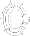
- Figure 2 assembled bottom view 100E
- Figure 3 exploded top view 100A
- Figure 4 exploded bottom view 100B
- Figure 5 section view
- FIG. 1 shown is a top view 10 of a fully-assembled CSF flow diverter. Shown is a top portion of a cover level 100D which includes the top portion of a multitude of holes 210D, 220D, 230D. The plurality of holes 210D, 220D, 230D are designed to be secured to the cranium via securing mechanisms such as medical screws (not shown). Also shown is the top portion of a nib 410D that is drilled all the way through the cover level 100D so as to allow limited access to levels below the cover level 100D.
- FIG. 2 shown is a bottom view 20 of a fully-assembled CSF flow diverter. Shown is the bottom portion of a cover level 100E which includes the bottom portion of a multitude of holes 210E, 220E, 230E. Also shown is the bottom portion of a membrane level 110E. This level consists of the bottom portion of the flexible membrane 310E that incorporates a chamber 350E above. The membrane level incorporates a side portion 650E that is tapered so as to provide the proper interference fit to a cranium of a patient.
- FIG. 30 shown is an exploded top view 30 showing the three levels of the CSF flow diverter: the cover level 100A, the membrane level 110A and the retaining level 120A.
- the cover level 100A shown includes the top portion of a plurality of holes 210A, 220A, 230A. Also shown is the top portion of a nib 410A that is drilled all the way through the cover level 100A so as to allow limited access to levels below the cover level 100A.
- the cover level 100A may consist of polyether ether ketone (PEEK) as well with a hydroxyapatite coating for bone adhesion.
- PEEK is a colorless organic thermoplastic polymer in the polyaryletherketone (PAEK) family.
- PEEK is an advanced biomaterial used in medical implants, including spinal fusion devices, reinforcing rods and other orthopedic procedures.
- the membrane level 110A incorporates a flexible membrane 310A which forms the bottom boundary of the chamber 350A (the top boundary being the cover level 100A).
- the membrane level 110A incorporates a side portion 650A that is tapered so as to provide the proper interference fit to a cranium of a patient.
- the top portion of the membrane level incorporates a plurality of sawtooth members 114A, 115A, 116A interspersed with a plurality of large cutouts 111A, 112A, 113A.
- the retaining level 120A incorporates a plurality of retaining members 124A, 125A, 126A interspersed with small cutouts 121A, 122A, 123A.
- the retaining level 120A is designed to secure the membrane level 110A to the cover level 100A so that the membrane level 120A is sandwiched in between.
- the small cutouts 121A, 122A, 123A allow access for the securing mechanisms (not shown) to pass through the plurality of holes 210A, 220A, 230A and into the cranium of the patient. Further the side portion 650A and the flexible membrane 310A pass through the hole 860A when so assembled.
- FIG. 4 shown is an exploded bottom view 40 showing the three levels of the CSF flow diverter: the cover level 100B, the membrane level 110B and the retaining level 120B.
- the cover level 100B shown includes the bottom portion of a plurality of holes 210B, 220B, 230B. Also shown is the bottom portion of a nib 410B that is drilled all the way through the cover level 100B.
- This view also shows the underside of the cover level 100B, showing a plurality of struts 520B providing structural support for the CSF flow diverter. Also shown is a stopper 500B attached to the struts 520B that is situated below the nib 410B.
- a plurality of tooth holders 802B, 804B, 806B that serve as a receptacle for portions of the membrane level 110B as discussed below.
- a monitoring/control mechanism 905B may be attached to the struts 520B and allow for the monitoring and/or control of the operation of the CSF flow diverter.
- the membrane level 110B incorporates a flexible membrane 310B which forms the bottom boundary of the chamber 350B (the top boundary being the cover level 100B).
- the membrane level 110B incorporates a side portion 650B that is tapered so as to provide the proper interference fit to a cranium of a patient.
- the top portion of the membrane level incorporates a plurality of sawtooth members 114B, 115B, 116B (116B is not shown) interspersed with a plurality of large cutouts 11B, 112B, 113B (111B, 112B are not shown).
- the sawtooth members 114B, 115B, 116B are designed to be bonded with the tooth holders 802B, 804B, 806B, thus securing the cover level 100B to the membrane level 110B
- the retaining level 120B is ring-shaped with a hole 860B that incorporates a plurality of retaining members 124B, 125B, 126B interspersed with small cutouts 121B, 122B, 123B.
- the retaining level 120B is designed to be bonded with the cover level 100B with the membrane level sandwiched in between.
- the small cutouts 121B, 122B, 123B allow access for the securing mechanisms (not shown) to pass through the plurality of holes 210B, 220B, 230B and into the cranium of the patient. Further the side portion 650B and the flexible membrane 310B pass through the hole 860B when so assembled.
- FIG. 5 shown is a front section view 50 of a fully-assembled CSF flow diverter. From this view, the interfacing of the cover level 100C, membrane level 110C and retaining level 120C among each other is readily observable. In particular, the bonded areas 710C, 720C show how the retaining level 120C is used to secure the membrane level 110C to the cover level 100C. Also shown is a cutaway of the struts 520C, the nib 410C, the stopper 500C, the chamber 350C, the flexible membrane 310C, the side portion 650C and the monitoring/control mechanism 905C.
- the cover level 100 may be made from polyether ether ketone (PEEK) as well with a hydroxyapatite coating for bone adhesion.
- PEEK is a colorless organic thermoplastic polymer in the polyaryletherketone (PAEK) family.
- PEEK is an advanced biomaterial used in medical implants, including spinal fusion devices, reinforcing rods and other orthopedic procedures.
- the cover level 100 may also be comprised of plastics, or titanium or other metals that may be compatible with MRIs and transparent to ultrasound.
- the nib 410 may be made from a rubber-like material through which a needle can be advanced with a rigid part to hold the rubber in place and a guard to prevent the needle from entering the chamber 350 too deeply.
- the membrane level 110 may also be made from PEEK, plastics, or titanium or other metals that may be compatible with MRIs and transparent to ultrasound, except that the flexible membrane 310 may be fabricated from materials such as ultra-high-molecular-weight polyethylene (UHMWPE) or the like compliant bio-compatible materials provides the compliance described herein.
- UHMWPE ultra-high-molecular-weight polyethylene
- the flexible membrane 310 may also be comprised of a flexible metal alloy diaphragm.
- the retaining level 120 may be made from PEEK, plastics, or titanium or other metals that may be compatible with MRIs and transparent to ultrasound.
- the CSF flow diverter is configured to reversibly increase the capacity of the cranial vault in response to a pressure change in the CSF.
- the CSF flow diverter is designed for placement in a craniotomy, or, in lay terms, a hole created surgically in the skull.
- a CSF flow diverter placed in the skull decreases CSF pressure gradients and thus reduces CSF flow through the foramen magnum, and reduces CSF velocities in the cervical spine.
- the CSF flow diverter may be located in a position may be placed in the craniotomy defect in place of a bone flap.
- the elastic chamber or cushion or materials in the chamber may be placed in the cranial vault.
- the device contains biocompatible materials where it is in contact with the human body.
- the CSF flow diverter may be made in variable sizes and configurations between 11 mm and 18 mm in diameter for example, or more particularly, 16.5 mm in diameter.
- the chamber 350 includes a compressible material located therein and the volume of the chamber 350 is selectively increased or decreased in volume by the ongoing displacement of the flexible membrane 310, thereby providing the desired clinical relief by diverting the CSF flow.
- the volume in the chamber a 350 may be modified by intervention from the treating physicians. For example, a surgeon or physician may administer or remove gas (e.g. nitrogen or oxygen) through the nib 410 into the chamber 350 to achieve suitable pressure to increase or decrease the overall diversion of the CSF flow.
- gas e.g. nitrogen or oxygen
- the stopper 500 is situated below the nib 410 so as to prevent the needle piercing the nib 410 from going beyond the stopper 500 and puncturing or damaging the flexible membrane 310.
- the chamber 350 may be filled with compressible gas such as oxygen or nitrogen (administered via the nib 410).
- compressible gas such as oxygen or nitrogen
- Other possibilities for inclusion in the chamber include: 1) a compressible tissue such as foam rubber or a compressible mechanism such as a chamber fitted with springs; 2) utilizing an electric or bio-powered control element such as a pump or "Shape Memory Alloy" wherein the shape is proportional to a controlled temperature that may be altered electronically by utilizing heating or cooling systems as well as the natural surrounding temperatures.
- the size of the chamber 350 may be designed to be directly proportional to the effect on CSF flow. For example, a circular chamber with a 1 cm diameter that moves 3 mm between systole and diastole would reduce Foramen Magnum flow in the average adult from 2 mL to 1 mL. Such movements would modify the CSF pressure to reduce CSF flow and reduce CSF velocities in the spine and improve patient comfort and reverse the growth of syringomyelia. Putting this another way, the chamber 350 may vary in volume by an exemplary 1 to 2 mL during the cardiac cycle, which serves to reduce the amount of fluid displaced from the cranial vault through the Foramen Magnum by any adjustable amount, such as from 50 to 100%.
- the chamber 350 may also include a monitoring/control mechanism 905, which may include a battery, sensors, transmitters and assorted housings.
- the monitoring/control mechanism 905 may include additional electronic elements designed to provide either near real time or a fixed pressure delivery protocol utilizing pressure sensors, strain gages, or the like designed to monitor and/or alter the operation of the chamber 350 and the flexible membrane 310.
- Well known wireless communication protocols not requiring the attachment of wires to the device may allow the surgeon to provide the necessary adjustments based on other external measurements and tests to provide a swift adjustment for the patient.
- CSF pressure may be modulated by the implantation and operation of an intraventricular balloon catheter.
- Shown in Figure 6 is a side sectional view of an intraventricular balloon catheter 60 incorporating a balloon lumen 916 and a trochar lumen 914 surrounded by a tube jacket 915.
- the tube jacket may comprise carbothane.
- the distal end of the balloon lumen 916 includes a balloon aperture 912 that is connected to the balloon 902.
- the balloon 902 surrounds all sides of the distal end of the tube jacket 915.
- the balloon may comprise urethane.
- the distal end of the trochar lumen 914 incorporates a trochar aperture 918, which is designed to be inserted into a lateral ventricular space within a patient.
- the trochar 904 itself may be selectively inserted and removed by the physician from the trochar lumen 914 to provide stiffness within the tube jacket 915.
- a hemostasis valve 906 On the proximal end of the trochar lumen 914 is a hemostasis valve 906 that can be sealed upon the withdrawal of the trochar 904 from the trochar lumen 914.
- the hemostasis valve 906 may also be accessed to allow CSF to be removed via a drainage catheter (not shown).
- the dual port hub 908 is capable of interfacing with a gas supply (not shown) to either add or withdraw gas from the chambers that are holding the gas, which include the balloon 902, the balloon lumen 916 and the balloon reservoir 910.
- the gas may comprise sterile air, nitrogen or other appropriate gases.
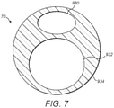
- FIG. 7 shown is a front sectional view of intraventricular balloon catheter 60 taken at the skull 920. Shown is a tube jacket cutaway 934 surrounding the balloon lumen cutaway 930 and the trochar lumen cutaway 932. As can be seen, the diameter of the balloon lumen cutaway 930 is smaller than the trochar lumen cutaway 932 because the balloon lumen 916 contains gas, which is less viscous. The trochar lumen 932 contains CSF and thus needs to be larger because the fluid is more viscous.
- the diameter of the balloon lumen cutaway 930 may be 0.508 mm (0.020 inches); the diameter of the trochar lumen cutaway 932 may be 0.8128 mm (0.032 inches) ; the diameter of the tube jacket cutaway may be 1.9812 mm (0.078 inches).
- Insertion of the intraventricular balloon catheter 60 in the patient may proceed as follows.
- the physician makes appropriate incisions in the scalp 922 and the skull 920 of the patient.
- the trochar 904 inserted into the trochar lumen 914 (to provide stiffness), and the balloon 902 deflated, the distal end of the intraventricular balloon catheter 60 is inserted through the scalp 922 and the skull 920 so that the trochar aperture 918 is inserted into a lateral ventricular space within a patient.
- the trochar 904 is removed from the trochar lumen 914 and the hemostasis valve 906 is sealed to prevent leakage of CSF.
- An appropriate amount of gas is inserted through the dual port hub into the balloon 902, the balloon lumen 916 and the balloon reservoir 910. This has the effect of inflating the balloon 902.
- a bend 919 is used to allow the proximal portion of the intraventricular balloon catheter 60 to be bent and tucked in between the scalp 922 and the skull 920.
- the scalp 922 is then repaired.
- the advantage of this placement is that if adjustment to the gas is necessary, the physician may adjust the gas by way of the dual port hub 908 by reopening the scalp 922 without needing to further access the skull 920 of the patient. Similarly, if adjustment to CSF is necessary, the physician may adjust the CSF by way of the hemostasis valve 906 without needing to further access the skull 920 of the patient.
- the effect of the intraventricular balloon catheter 60 is to reduce the amount of fluid forced from the cranial vault into the upper cervical spinal canal during systole.
- the intraventricular balloon catheter 60 reduces spinal fluid movement, CSF velocities, CSF pressure gradients and CSF pressure wave magnitudes in the Foramen Magnum.
- Another embodiment may be a chamber to place in a craniotomy site over which a rigid plate, for example a metal plate, is placed.
- a rigid plate for example a metal plate
- Another embodiment is a smaller, simpler device for veterinary use in for example Cavalier King Charles Dogls that frequently have tonsil malformations and syringomyelia and symptoms such as weakness in the limbs.
- Another embodiment may be a chamber placed outside the skull that has a sufficiently large channel communicating with the intracranial chamber such that changes in CSF pressure cause fluid or gas or tissue to move reversibly between the external chamber and the intracranial chamber. It improves compliance of the cranial vault, modulates CSF pressures and damps CSF pressure waves such as pressure waves occurring in association with the cardiac cycle.
- the described inventive matter may also have applications in other disorders. Applications are anticipated in a less frequent condition; Idiopathic Syringomyelia, which is syringomyelia without a Chiari I malformation. It may have applications in Normal Pressure Hydrocephalus, a condition that has abnormal CSF pressure waves, which are often the object of surgical treatment with shunting (Bradley 2000). Since Normal Pressure Hydrocephalus is characterized by abnormally low cranial compliance, use of the device in these patients may be effective. The device may provide more effective control of CSF pressures than conventional shunting in patients with some types of transient CSF pressure fluctuations due, for example, to coughing or sneezing.
- the use of the device will serve to decrease the fluctuations in CSF pressure due to the cardiac cycle, possibly reducing CSF leakage and aiding in the healing of the traumatic dural defects.
- the described matter seeks to improve compliance, modulate CSF pressures and damp CSF pressure waves such as those occurring with the cardiac cycle.
Claims (12)
- Liquor-Ableiter mit:einer Abdeckebene (100D) mit einer Abdeckungsoberseite und einer Abdeckungsunterseite, wobei die Abdeckebene (100D) eine kappenartige Struktur mit einer Mehrzahl von Befestigungslöchern (210D, 220D, 230D) von der Abdeckungsoberseite bis zur Abdeckungsunterseite umfasst;einer Membranebene (20), wobei die Membranebene (20) eine Mehrzahl von Membranebenen-Befestigungselementen, eine flexible Membran (310E), einen verjüngten Seitenabschnitt (650E) und eine Kammer (350E) umfasst, wobei die flexible Membran (310E) die untere Begrenzung der Kammer bildet und diese abdeckt;einer Rückhalteebene, die eine ringartige Struktur (124A) mit einem im Wesentlichen kreisförmigen Rückhalteelement (120A) mit einer hohlen Mitte (860A) umfasst;einer Mehrzahl von Schädelbefestigungsmechanismen, die durch die Mehrzahl von Befestigungslöchern und in den Schädel des Patienten verlaufen;einer Nase (410D), die durch die Oberseite der Abdeckung und durch die Unterseite der Abdeckung verläuft und sich in die Kammer (350E) öffnet;wobei die Membranebene (20) an der Abdeckungsunterseite befestigt ist, indem die Mehrzahl von Befestigungselementen der Membranebene zwischen dem im Wesentlichen kreisförmigen Halteelement (120A) und der Abdeckungsunterseite befestigt ist, so dass die flexible Membran (310E), der verjüngte Seitenabschnitt (650E) und die Kammer (350E) durch die hohle Mitte (860A) des im Wesentlichen kreisförmigen Halteelements (120A) verlaufen und die Oberseite der Kammer (350E) von der Abdeckungsunterseite bedeckt ist;wobei die Kammer (350E) mit komprimierbarem Material gefüllt ist;wobei nach dem Einsetzen des verjüngten Seitenabschnitts (650E) und der flexiblen Membran (310E) in den Schädel eines Patienten das Volumen der Kammer (350E) durch die fortlaufende Verschiebung der flexiblen Membran (310E) während eines Herzzyklus im Patienten selektiv vergrößert und verkleinert wird, wodurch der Liquorfluss im Patienten moduliert wird.
- Liquor-Ableiter nach Anspruch 1, ferner mit einem Stopper (500B), der in der Kammer (350) in der Nähe des sich in die Kammer (350E) öffnenden Endes der Nase (410D) angebracht ist, um eine Beschädigung der flexiblen Membran (310E) zu verhindern.
- Liquor-Ableiter nach Anspruch 2, wobei das komprimierbare Material ein komprimierbares Gas ist.
- Liquor-Ableiter nach Anspruch 3, wobei der Druck des Gases in der Kammer durch Einleiten und Ableiten des Gases über die Nase (410D) einstellbar ist.
- Liquor-Ableiter nach Anspruch 4, wobei die Größe des Liquor-Ableiters einen Durchmesser zwischen 11 mm und 18 mm aufweist.
- Liquor-Ableiter nach Anspruch 4, bei dem der Durchmesser des Liquor-Ableiters 1 cm beträgt, der sich zwischen Systole und Diastole um 3 mm bewegt, und das Volumen der Kammer während eines Herzzyklus des Patienten zwischen 1 ml und 2 ml schwankt.
- Liquor-Ableiter nach Anspruch 1, ferner mit Kontrollsensoren in der Kammer zur Überwachung und Steuerung des Zustands des komprimierbaren Materials und der flexiblen Membran (310E).
- Liquor-Ableiter nach Anspruch 7, bei dem die Kontrollsensoren über drahtlose Kommunikationsprotokolle kommunizieren.
- Liquor-Ableiter nach Anspruch 1, bei dem die flexible Membran (310E) biokompatibles ultrahochmolekulares Polyethylen umfasst.
- Liquor-Ableiter nach Anspruch 1, bei dem die Abdeckebene (100D) biokompatibles Polyetheretherketon umfasst.
- Liquor-Ableiter nach Anspruch 1, bei dem das komprimierbare Material ein komprimierbares Gewebe ist.
- Liquor-Ableiter mit:einer Abdeckebene (100D) mit einer Abdeckungsoberseite und einer Abdeckungsunterseite, wobei die Abdeckebene (100D) eine kappenartige Struktur mit einer Mehrzahl von Befestigungslöchern (210D, 220D, 230D) von der Abdeckungsoberseite bis zur Abdeckungsunterseite umfasst;einer Membranebene (20), wobei die Membranebene (20) eine Mehrzahl von Membranebenen-Befestigungselementen, eine flexible Membran (310E), einen verjüngten Seitenabschnitt (650E) und eine Kammer (350E) umfasst, wobei die flexible Membran (310E) die untere Begrenzung der Kammer bildet und diese abdeckt;eine Rückhalteebene, die eine ringartige Struktur (124A) mit einem im Wesentlichen kreisförmigen Rückhalteelement (120A) mit einer hohlen Mitte (860A) umfasst;einer Mehrzahl von Schädelbefestigungsmechanismen, die durch die Mehrzahl von Befestigungslöchern und in den Schädel des Patienten verlaufen;einer Nase (410D), die durch die Oberseite der Abdeckung und durch die Unterseite der Abdeckung verläuft und sich in die Kammer (350E) öffnet;wobei die Membranebene (20) an der Abdeckungsunterseite befestigt ist, indem die Mehrzahl von Befestigungselementen der Membranebene zwischen dem im Wesentlichen kreisförmigen Halteelement (120A) und der Abdeckungsunterseite befestigt ist, so dass die flexible Membran (310E), der verjüngte Seitenabschnitt (650E) und die Kammer (350E) durch die hohle Mitte (860A) des im Wesentlichen kreisförmigen Halteelements (120A) verlaufen und die Oberseite der Kammer (350E) von der Abdeckungsunterseite bedeckt ist;wobei die Kammer (350E) mit einer Formgedächtnislegierung gefüllt ist, wobei die Form der Formgedächtnislegierung proportional zu einer gesteuerten Temperatur in der Kammer ist, die unter Verwendung von Heiz- oder Kühlsystemen veränderbar ist;wobei nach dem Einsetzen des verjüngten Seitenteils (650E) und der flexiblen Membran (310E) in den Schädel eines Patienten das Volumen der Kammer (350E) durch die fortlaufende Verschiebung der flexiblen Membran (310E) während eines Herzzyklus im Patienten selektiv vergrößert und verkleinert wird, wodurch der Liquorfluss im Patienten moduliert wird.
Applications Claiming Priority (2)
| Application Number | Priority Date | Filing Date | Title |
|---|---|---|---|
| US201562173820P | 2015-06-10 | 2015-06-10 | |
| PCT/US2016/036458 WO2016200949A1 (en) | 2015-06-10 | 2016-06-08 | Cerebrospinal fluid flow diverter |
Publications (3)
| Publication Number | Publication Date |
|---|---|
| EP3307148A1 EP3307148A1 (de) | 2018-04-18 |
| EP3307148A4 EP3307148A4 (de) | 2019-04-03 |
| EP3307148B1 true EP3307148B1 (de) | 2022-03-23 |
Family
ID=61597847
Family Applications (1)
| Application Number | Title | Priority Date | Filing Date |
|---|---|---|---|
| EP16808195.8A Active EP3307148B1 (de) | 2015-06-10 | 2016-06-08 | Flussumleiter für liquor |
Country Status (1)
| Country | Link |
|---|---|
| EP (1) | EP3307148B1 (de) |
Family Cites Families (9)
| Publication number | Priority date | Publication date | Assignee | Title |
|---|---|---|---|---|
| US3583387A (en) * | 1968-12-20 | 1971-06-08 | John T Garner | Pressure absorbing appliance for treating hydrocephalus |
| FR2274261A1 (fr) * | 1974-06-11 | 1976-01-09 | Electronique Appliquee | Sonde intra-cranienne perfectionnee |
| US4026276A (en) * | 1976-04-05 | 1977-05-31 | The Johns Hopkins University | Intracranial pressure monitor |
| US4127110A (en) * | 1976-05-24 | 1978-11-28 | Huntington Institute Of Applied Medical Research | Implantable pressure transducer |
| DE8811322U1 (de) * | 1988-09-07 | 1988-11-17 | Spiegelberg Kg, 2100 Hamburg, De | |
| US5873840A (en) * | 1997-08-21 | 1999-02-23 | Neff; Samuel R. | Intracranial pressure monitoring system |
| US7309330B2 (en) * | 2004-07-20 | 2007-12-18 | Medtronic, Inc. | Implantable cerebral spinal fluid drainage device and method of draining cerebral spinal fluid |
| US20110160609A1 (en) * | 2009-12-29 | 2011-06-30 | Stone Robert T | Method and system for monitoring pressure in a body cavity |
| ITMI20120097A1 (it) * | 2012-01-27 | 2013-07-28 | Siad Healthcare Spa | Dispositivo impiantabile migliorato per il trattamento della patologia idrocefalica e corrispondente metodo |
-
2016
- 2016-06-08 EP EP16808195.8A patent/EP3307148B1/de active Active
Non-Patent Citations (1)
| Title |
|---|
| None * |
Also Published As
| Publication number | Publication date |
|---|---|
| EP3307148A1 (de) | 2018-04-18 |
| EP3307148A4 (de) | 2019-04-03 |
Similar Documents
| Publication | Publication Date | Title |
|---|---|---|
| US11311703B2 (en) | Cerebrospinal fluid flow diverter | |
| Antes et al. | Telemetric intracranial pressure monitoring with the Raumedic Neurovent P-tel | |
| Muralidharan | External ventricular drains: Management and complications | |
| US8313453B2 (en) | Burr hole sealing device for preventing brain shift | |
| JP7450589B2 (ja) | モジュール化された超音波対応人工頭蓋プロテーゼ | |
| US7025739B2 (en) | System and method for treating elevated intracranial pressure | |
| CA2356032C (en) | Shunt | |
| US6913589B2 (en) | Multi-catheter insertion device and method | |
| US20200375745A1 (en) | Ultra-sound compatible artificial cranial prosthesis with customized platforms | |
| Jorgensen et al. | Hydrocephalus and ventriculoperitoneal shunts: modes of failure and opportunities for improvement | |
| US10595902B2 (en) | Self-actuating growing rod systems | |
| WO2018005621A1 (en) | Devices and methods for accessing subarachnoid space | |
| US11298232B2 (en) | Cranial implant with dural window | |
| KR20230095057A (ko) | 환자 치료를 위한 체액 관리 시스템 | |
| US20050010159A1 (en) | Csf physiologic controller | |
| EP3307148B1 (de) | Flussumleiter für liquor | |
| JP5750555B2 (ja) | 水頭症シャント設定の最適化 | |
| Børgesen et al. | Shunting to the cranial venous sinus using the SinuShunt | |
| US20240099848A1 (en) | Implantable Medical Device for Modulation of Cerebrospinal Fluid and Glymphatic Flow | |
| US20220401260A1 (en) | Device and method for cerebral temperature control | |
| Mahat et al. | Caring of Neurosurgical Patients with External Ventricular Drain | |
| KR20200031457A (ko) | 이식형 저류장치 | |
| Brock et al. | The significance of continuous recording of intracranial pressure in children with brain tumours | |
| Johnson et al. | The subarachnoid screw | |
| Goloskov et al. | A new method for managing extracellular fluid accumulations in central nervous system disorders |
Legal Events
| Date | Code | Title | Description |
|---|---|---|---|
| STAA | Information on the status of an ep patent application or granted ep patent |
Free format text: STATUS: THE INTERNATIONAL PUBLICATION HAS BEEN MADE |
|
| PUAI | Public reference made under article 153(3) epc to a published international application that has entered the european phase |
Free format text: ORIGINAL CODE: 0009012 |
|
| STAA | Information on the status of an ep patent application or granted ep patent |
Free format text: STATUS: REQUEST FOR EXAMINATION WAS MADE |
|
| 17P | Request for examination filed |
Effective date: 20180102 |
|
| AK | Designated contracting states |
Kind code of ref document: A1 Designated state(s): AL AT BE BG CH CY CZ DE DK EE ES FI FR GB GR HR HU IE IS IT LI LT LU LV MC MK MT NL NO PL PT RO RS SE SI SK SM TR |
|
| AX | Request for extension of the european patent |
Extension state: BA ME |
|
| DAV | Request for validation of the european patent (deleted) | ||
| DAX | Request for extension of the european patent (deleted) | ||
| A4 | Supplementary search report drawn up and despatched |
Effective date: 20190306 |
|
| RIC1 | Information provided on ipc code assigned before grant |
Ipc: A61M 27/00 20060101ALI20190227BHEP Ipc: A61M 25/10 20130101ALI20190227BHEP Ipc: A61B 5/03 20060101AFI20190227BHEP Ipc: G01L 19/08 20060101ALI20190227BHEP Ipc: A61M 39/06 20060101ALI20190227BHEP Ipc: A61M 25/00 20060101ALI20190227BHEP Ipc: G01L 19/14 20060101ALI20190227BHEP Ipc: A61M 1/36 20060101ALI20190227BHEP |
|
| STAA | Information on the status of an ep patent application or granted ep patent |
Free format text: STATUS: EXAMINATION IS IN PROGRESS |
|
| 17Q | First examination report despatched |
Effective date: 20200424 |
|
| STAA | Information on the status of an ep patent application or granted ep patent |
Free format text: STATUS: EXAMINATION IS IN PROGRESS |
|
| GRAP | Despatch of communication of intention to grant a patent |
Free format text: ORIGINAL CODE: EPIDOSNIGR1 |
|
| STAA | Information on the status of an ep patent application or granted ep patent |
Free format text: STATUS: GRANT OF PATENT IS INTENDED |
|
| INTG | Intention to grant announced |
Effective date: 20211014 |
|
| GRAS | Grant fee paid |
Free format text: ORIGINAL CODE: EPIDOSNIGR3 |
|
| GRAA | (expected) grant |
Free format text: ORIGINAL CODE: 0009210 |
|
| STAA | Information on the status of an ep patent application or granted ep patent |
Free format text: STATUS: THE PATENT HAS BEEN GRANTED |
|
| AK | Designated contracting states |
Kind code of ref document: B1 Designated state(s): AL AT BE BG CH CY CZ DE DK EE ES FI FR GB GR HR HU IE IS IT LI LT LU LV MC MK MT NL NO PL PT RO RS SE SI SK SM TR |
|
| REG | Reference to a national code |
Ref country code: GB Ref legal event code: FG4D |
|
| REG | Reference to a national code |
Ref country code: CH Ref legal event code: EP |
|
| REG | Reference to a national code |
Ref country code: DE Ref legal event code: R096 Ref document number: 602016070324 Country of ref document: DE |
|
| REG | Reference to a national code |
Ref country code: IE Ref legal event code: FG4D |
|
| REG | Reference to a national code |
Ref country code: AT Ref legal event code: REF Ref document number: 1476894 Country of ref document: AT Kind code of ref document: T Effective date: 20220415 |
|
| REG | Reference to a national code |
Ref country code: LT Ref legal event code: MG9D |
|
| REG | Reference to a national code |
Ref country code: NL Ref legal event code: MP Effective date: 20220323 |
|
| PG25 | Lapsed in a contracting state [announced via postgrant information from national office to epo] |
Ref country code: SE Free format text: LAPSE BECAUSE OF FAILURE TO SUBMIT A TRANSLATION OF THE DESCRIPTION OR TO PAY THE FEE WITHIN THE PRESCRIBED TIME-LIMIT Effective date: 20220323 Ref country code: RS Free format text: LAPSE BECAUSE OF FAILURE TO SUBMIT A TRANSLATION OF THE DESCRIPTION OR TO PAY THE FEE WITHIN THE PRESCRIBED TIME-LIMIT Effective date: 20220323 Ref country code: NO Free format text: LAPSE BECAUSE OF FAILURE TO SUBMIT A TRANSLATION OF THE DESCRIPTION OR TO PAY THE FEE WITHIN THE PRESCRIBED TIME-LIMIT Effective date: 20220623 Ref country code: LT Free format text: LAPSE BECAUSE OF FAILURE TO SUBMIT A TRANSLATION OF THE DESCRIPTION OR TO PAY THE FEE WITHIN THE PRESCRIBED TIME-LIMIT Effective date: 20220323 Ref country code: HR Free format text: LAPSE BECAUSE OF FAILURE TO SUBMIT A TRANSLATION OF THE DESCRIPTION OR TO PAY THE FEE WITHIN THE PRESCRIBED TIME-LIMIT Effective date: 20220323 Ref country code: BG Free format text: LAPSE BECAUSE OF FAILURE TO SUBMIT A TRANSLATION OF THE DESCRIPTION OR TO PAY THE FEE WITHIN THE PRESCRIBED TIME-LIMIT Effective date: 20220623 |
|
| REG | Reference to a national code |
Ref country code: AT Ref legal event code: MK05 Ref document number: 1476894 Country of ref document: AT Kind code of ref document: T Effective date: 20220323 |
|
| PG25 | Lapsed in a contracting state [announced via postgrant information from national office to epo] |
Ref country code: LV Free format text: LAPSE BECAUSE OF FAILURE TO SUBMIT A TRANSLATION OF THE DESCRIPTION OR TO PAY THE FEE WITHIN THE PRESCRIBED TIME-LIMIT Effective date: 20220323 Ref country code: GR Free format text: LAPSE BECAUSE OF FAILURE TO SUBMIT A TRANSLATION OF THE DESCRIPTION OR TO PAY THE FEE WITHIN THE PRESCRIBED TIME-LIMIT Effective date: 20220624 Ref country code: FI Free format text: LAPSE BECAUSE OF FAILURE TO SUBMIT A TRANSLATION OF THE DESCRIPTION OR TO PAY THE FEE WITHIN THE PRESCRIBED TIME-LIMIT Effective date: 20220323 |
|
| PG25 | Lapsed in a contracting state [announced via postgrant information from national office to epo] |
Ref country code: NL Free format text: LAPSE BECAUSE OF FAILURE TO SUBMIT A TRANSLATION OF THE DESCRIPTION OR TO PAY THE FEE WITHIN THE PRESCRIBED TIME-LIMIT Effective date: 20220323 |
|
| PG25 | Lapsed in a contracting state [announced via postgrant information from national office to epo] |
Ref country code: SM Free format text: LAPSE BECAUSE OF FAILURE TO SUBMIT A TRANSLATION OF THE DESCRIPTION OR TO PAY THE FEE WITHIN THE PRESCRIBED TIME-LIMIT Effective date: 20220323 Ref country code: SK Free format text: LAPSE BECAUSE OF FAILURE TO SUBMIT A TRANSLATION OF THE DESCRIPTION OR TO PAY THE FEE WITHIN THE PRESCRIBED TIME-LIMIT Effective date: 20220323 Ref country code: RO Free format text: LAPSE BECAUSE OF FAILURE TO SUBMIT A TRANSLATION OF THE DESCRIPTION OR TO PAY THE FEE WITHIN THE PRESCRIBED TIME-LIMIT Effective date: 20220323 Ref country code: PT Free format text: LAPSE BECAUSE OF FAILURE TO SUBMIT A TRANSLATION OF THE DESCRIPTION OR TO PAY THE FEE WITHIN THE PRESCRIBED TIME-LIMIT Effective date: 20220725 Ref country code: ES Free format text: LAPSE BECAUSE OF FAILURE TO SUBMIT A TRANSLATION OF THE DESCRIPTION OR TO PAY THE FEE WITHIN THE PRESCRIBED TIME-LIMIT Effective date: 20220323 Ref country code: EE Free format text: LAPSE BECAUSE OF FAILURE TO SUBMIT A TRANSLATION OF THE DESCRIPTION OR TO PAY THE FEE WITHIN THE PRESCRIBED TIME-LIMIT Effective date: 20220323 Ref country code: CZ Free format text: LAPSE BECAUSE OF FAILURE TO SUBMIT A TRANSLATION OF THE DESCRIPTION OR TO PAY THE FEE WITHIN THE PRESCRIBED TIME-LIMIT Effective date: 20220323 Ref country code: AT Free format text: LAPSE BECAUSE OF FAILURE TO SUBMIT A TRANSLATION OF THE DESCRIPTION OR TO PAY THE FEE WITHIN THE PRESCRIBED TIME-LIMIT Effective date: 20220323 |
|
| PG25 | Lapsed in a contracting state [announced via postgrant information from national office to epo] |
Ref country code: PL Free format text: LAPSE BECAUSE OF FAILURE TO SUBMIT A TRANSLATION OF THE DESCRIPTION OR TO PAY THE FEE WITHIN THE PRESCRIBED TIME-LIMIT Effective date: 20220323 Ref country code: IS Free format text: LAPSE BECAUSE OF FAILURE TO SUBMIT A TRANSLATION OF THE DESCRIPTION OR TO PAY THE FEE WITHIN THE PRESCRIBED TIME-LIMIT Effective date: 20220723 Ref country code: AL Free format text: LAPSE BECAUSE OF FAILURE TO SUBMIT A TRANSLATION OF THE DESCRIPTION OR TO PAY THE FEE WITHIN THE PRESCRIBED TIME-LIMIT Effective date: 20220323 |
|
| REG | Reference to a national code |
Ref country code: DE Ref legal event code: R097 Ref document number: 602016070324 Country of ref document: DE |
|
| PLBE | No opposition filed within time limit |
Free format text: ORIGINAL CODE: 0009261 |
|
| STAA | Information on the status of an ep patent application or granted ep patent |
Free format text: STATUS: NO OPPOSITION FILED WITHIN TIME LIMIT |
|
| PG25 | Lapsed in a contracting state [announced via postgrant information from national office to epo] |
Ref country code: MC Free format text: LAPSE BECAUSE OF FAILURE TO SUBMIT A TRANSLATION OF THE DESCRIPTION OR TO PAY THE FEE WITHIN THE PRESCRIBED TIME-LIMIT Effective date: 20220323 Ref country code: DK Free format text: LAPSE BECAUSE OF FAILURE TO SUBMIT A TRANSLATION OF THE DESCRIPTION OR TO PAY THE FEE WITHIN THE PRESCRIBED TIME-LIMIT Effective date: 20220323 |
|
| REG | Reference to a national code |
Ref country code: CH Ref legal event code: PL |
|
| REG | Reference to a national code |
Ref country code: BE Ref legal event code: MM Effective date: 20220630 |
|
| 26N | No opposition filed |
Effective date: 20230102 |
|
| PG25 | Lapsed in a contracting state [announced via postgrant information from national office to epo] |
Ref country code: LU Free format text: LAPSE BECAUSE OF NON-PAYMENT OF DUE FEES Effective date: 20220608 Ref country code: LI Free format text: LAPSE BECAUSE OF NON-PAYMENT OF DUE FEES Effective date: 20220630 Ref country code: IE Free format text: LAPSE BECAUSE OF NON-PAYMENT OF DUE FEES Effective date: 20220608 Ref country code: CH Free format text: LAPSE BECAUSE OF NON-PAYMENT OF DUE FEES Effective date: 20220630 |
|
| PG25 | Lapsed in a contracting state [announced via postgrant information from national office to epo] |
Ref country code: SI Free format text: LAPSE BECAUSE OF FAILURE TO SUBMIT A TRANSLATION OF THE DESCRIPTION OR TO PAY THE FEE WITHIN THE PRESCRIBED TIME-LIMIT Effective date: 20220323 Ref country code: BE Free format text: LAPSE BECAUSE OF NON-PAYMENT OF DUE FEES Effective date: 20220630 |
|
| PG25 | Lapsed in a contracting state [announced via postgrant information from national office to epo] |
Ref country code: IT Free format text: LAPSE BECAUSE OF FAILURE TO SUBMIT A TRANSLATION OF THE DESCRIPTION OR TO PAY THE FEE WITHIN THE PRESCRIBED TIME-LIMIT Effective date: 20220323 |
|
| PGFP | Annual fee paid to national office [announced via postgrant information from national office to epo] |
Ref country code: FR Payment date: 20230619 Year of fee payment: 8 Ref country code: DE Payment date: 20230621 Year of fee payment: 8 |
|
| PGFP | Annual fee paid to national office [announced via postgrant information from national office to epo] |
Ref country code: GB Payment date: 20230619 Year of fee payment: 8 |
|
| PG25 | Lapsed in a contracting state [announced via postgrant information from national office to epo] |
Ref country code: HU Free format text: LAPSE BECAUSE OF FAILURE TO SUBMIT A TRANSLATION OF THE DESCRIPTION OR TO PAY THE FEE WITHIN THE PRESCRIBED TIME-LIMIT; INVALID AB INITIO Effective date: 20160608 |
|
| PG25 | Lapsed in a contracting state [announced via postgrant information from national office to epo] |
Ref country code: MK Free format text: LAPSE BECAUSE OF FAILURE TO SUBMIT A TRANSLATION OF THE DESCRIPTION OR TO PAY THE FEE WITHIN THE PRESCRIBED TIME-LIMIT Effective date: 20220323 Ref country code: CY Free format text: LAPSE BECAUSE OF FAILURE TO SUBMIT A TRANSLATION OF THE DESCRIPTION OR TO PAY THE FEE WITHIN THE PRESCRIBED TIME-LIMIT Effective date: 20220323 |