EP3307128B1 - Automatisierter bodenreiniger - Google Patents
Automatisierter bodenreiniger Download PDFInfo
- Publication number
- EP3307128B1 EP3307128B1 EP16729610.2A EP16729610A EP3307128B1 EP 3307128 B1 EP3307128 B1 EP 3307128B1 EP 16729610 A EP16729610 A EP 16729610A EP 3307128 B1 EP3307128 B1 EP 3307128B1
- Authority
- EP
- European Patent Office
- Prior art keywords
- belt
- floor cleaner
- cleaner
- floor
- automated
- Prior art date
- Legal status (The legal status is an assumption and is not a legal conclusion. Google has not performed a legal analysis and makes no representation as to the accuracy of the status listed.)
- Active
Links
Images


Classifications
-
- A—HUMAN NECESSITIES
- A47—FURNITURE; DOMESTIC ARTICLES OR APPLIANCES; COFFEE MILLS; SPICE MILLS; SUCTION CLEANERS IN GENERAL
- A47L—DOMESTIC WASHING OR CLEANING; SUCTION CLEANERS IN GENERAL
- A47L11/00—Machines for cleaning floors, carpets, furniture, walls, or wall coverings
- A47L11/40—Parts or details of machines not provided for in groups A47L11/02 - A47L11/38, or not restricted to one of these groups, e.g. handles, arrangements of switches, skirts, buffers, levers
- A47L11/4036—Parts or details of the surface treating tools
- A47L11/4047—Wound-up or endless cleaning belts
-
- A—HUMAN NECESSITIES
- A47—FURNITURE; DOMESTIC ARTICLES OR APPLIANCES; COFFEE MILLS; SPICE MILLS; SUCTION CLEANERS IN GENERAL
- A47L—DOMESTIC WASHING OR CLEANING; SUCTION CLEANERS IN GENERAL
- A47L11/00—Machines for cleaning floors, carpets, furniture, walls, or wall coverings
- A47L11/29—Floor-scrubbing machines characterised by means for taking-up dirty liquid
- A47L11/30—Floor-scrubbing machines characterised by means for taking-up dirty liquid by suction
- A47L11/302—Floor-scrubbing machines characterised by means for taking-up dirty liquid by suction having rotary tools
-
- A—HUMAN NECESSITIES
- A47—FURNITURE; DOMESTIC ARTICLES OR APPLIANCES; COFFEE MILLS; SPICE MILLS; SUCTION CLEANERS IN GENERAL
- A47L—DOMESTIC WASHING OR CLEANING; SUCTION CLEANERS IN GENERAL
- A47L11/00—Machines for cleaning floors, carpets, furniture, walls, or wall coverings
- A47L11/40—Parts or details of machines not provided for in groups A47L11/02 - A47L11/38, or not restricted to one of these groups, e.g. handles, arrangements of switches, skirts, buffers, levers
- A47L11/4011—Regulation of the cleaning machine by electric means; Control systems and remote control systems therefor
-
- A—HUMAN NECESSITIES
- A47—FURNITURE; DOMESTIC ARTICLES OR APPLIANCES; COFFEE MILLS; SPICE MILLS; SUCTION CLEANERS IN GENERAL
- A47L—DOMESTIC WASHING OR CLEANING; SUCTION CLEANERS IN GENERAL
- A47L11/00—Machines for cleaning floors, carpets, furniture, walls, or wall coverings
- A47L11/40—Parts or details of machines not provided for in groups A47L11/02 - A47L11/38, or not restricted to one of these groups, e.g. handles, arrangements of switches, skirts, buffers, levers
- A47L11/4013—Contaminants collecting devices, i.e. hoppers, tanks or the like
- A47L11/4016—Contaminants collecting devices, i.e. hoppers, tanks or the like specially adapted for collecting fluids
- A47L11/4022—Contaminants collecting devices, i.e. hoppers, tanks or the like specially adapted for collecting fluids with means for recycling the dirty liquid
-
- A—HUMAN NECESSITIES
- A47—FURNITURE; DOMESTIC ARTICLES OR APPLIANCES; COFFEE MILLS; SPICE MILLS; SUCTION CLEANERS IN GENERAL
- A47L—DOMESTIC WASHING OR CLEANING; SUCTION CLEANERS IN GENERAL
- A47L11/00—Machines for cleaning floors, carpets, furniture, walls, or wall coverings
- A47L11/40—Parts or details of machines not provided for in groups A47L11/02 - A47L11/38, or not restricted to one of these groups, e.g. handles, arrangements of switches, skirts, buffers, levers
- A47L11/4036—Parts or details of the surface treating tools
- A47L11/4044—Vacuuming or pick-up tools; Squeegees
-
- A—HUMAN NECESSITIES
- A47—FURNITURE; DOMESTIC ARTICLES OR APPLIANCES; COFFEE MILLS; SPICE MILLS; SUCTION CLEANERS IN GENERAL
- A47L—DOMESTIC WASHING OR CLEANING; SUCTION CLEANERS IN GENERAL
- A47L11/00—Machines for cleaning floors, carpets, furniture, walls, or wall coverings
- A47L11/40—Parts or details of machines not provided for in groups A47L11/02 - A47L11/38, or not restricted to one of these groups, e.g. handles, arrangements of switches, skirts, buffers, levers
- A47L11/4036—Parts or details of the surface treating tools
- A47L11/405—Machines using UV-lamps, IR-lamps, ultrasound or plasma cleaning
-
- A—HUMAN NECESSITIES
- A47—FURNITURE; DOMESTIC ARTICLES OR APPLIANCES; COFFEE MILLS; SPICE MILLS; SUCTION CLEANERS IN GENERAL
- A47L—DOMESTIC WASHING OR CLEANING; SUCTION CLEANERS IN GENERAL
- A47L11/00—Machines for cleaning floors, carpets, furniture, walls, or wall coverings
- A47L11/40—Parts or details of machines not provided for in groups A47L11/02 - A47L11/38, or not restricted to one of these groups, e.g. handles, arrangements of switches, skirts, buffers, levers
- A47L11/4061—Steering means; Means for avoiding obstacles; Details related to the place where the driver is accommodated
-
- A—HUMAN NECESSITIES
- A47—FURNITURE; DOMESTIC ARTICLES OR APPLIANCES; COFFEE MILLS; SPICE MILLS; SUCTION CLEANERS IN GENERAL
- A47L—DOMESTIC WASHING OR CLEANING; SUCTION CLEANERS IN GENERAL
- A47L11/00—Machines for cleaning floors, carpets, furniture, walls, or wall coverings
- A47L11/40—Parts or details of machines not provided for in groups A47L11/02 - A47L11/38, or not restricted to one of these groups, e.g. handles, arrangements of switches, skirts, buffers, levers
- A47L11/4063—Driving means; Transmission means therefor
- A47L11/4066—Propulsion of the whole machine
-
- A—HUMAN NECESSITIES
- A47—FURNITURE; DOMESTIC ARTICLES OR APPLIANCES; COFFEE MILLS; SPICE MILLS; SUCTION CLEANERS IN GENERAL
- A47L—DOMESTIC WASHING OR CLEANING; SUCTION CLEANERS IN GENERAL
- A47L11/00—Machines for cleaning floors, carpets, furniture, walls, or wall coverings
- A47L11/40—Parts or details of machines not provided for in groups A47L11/02 - A47L11/38, or not restricted to one of these groups, e.g. handles, arrangements of switches, skirts, buffers, levers
- A47L11/4063—Driving means; Transmission means therefor
- A47L11/4069—Driving or transmission means for the cleaning tools
-
- A—HUMAN NECESSITIES
- A47—FURNITURE; DOMESTIC ARTICLES OR APPLIANCES; COFFEE MILLS; SPICE MILLS; SUCTION CLEANERS IN GENERAL
- A47L—DOMESTIC WASHING OR CLEANING; SUCTION CLEANERS IN GENERAL
- A47L11/00—Machines for cleaning floors, carpets, furniture, walls, or wall coverings
- A47L11/40—Parts or details of machines not provided for in groups A47L11/02 - A47L11/38, or not restricted to one of these groups, e.g. handles, arrangements of switches, skirts, buffers, levers
- A47L11/4072—Arrangement of castors or wheels
-
- A—HUMAN NECESSITIES
- A47—FURNITURE; DOMESTIC ARTICLES OR APPLIANCES; COFFEE MILLS; SPICE MILLS; SUCTION CLEANERS IN GENERAL
- A47L—DOMESTIC WASHING OR CLEANING; SUCTION CLEANERS IN GENERAL
- A47L11/00—Machines for cleaning floors, carpets, furniture, walls, or wall coverings
- A47L11/40—Parts or details of machines not provided for in groups A47L11/02 - A47L11/38, or not restricted to one of these groups, e.g. handles, arrangements of switches, skirts, buffers, levers
- A47L11/408—Means for supplying cleaning or surface treating agents
- A47L11/4083—Liquid supply reservoirs; Preparation of the agents, e.g. mixing devices
-
- A—HUMAN NECESSITIES
- A47—FURNITURE; DOMESTIC ARTICLES OR APPLIANCES; COFFEE MILLS; SPICE MILLS; SUCTION CLEANERS IN GENERAL
- A47L—DOMESTIC WASHING OR CLEANING; SUCTION CLEANERS IN GENERAL
- A47L11/00—Machines for cleaning floors, carpets, furniture, walls, or wall coverings
- A47L11/40—Parts or details of machines not provided for in groups A47L11/02 - A47L11/38, or not restricted to one of these groups, e.g. handles, arrangements of switches, skirts, buffers, levers
- A47L11/408—Means for supplying cleaning or surface treating agents
- A47L11/4088—Supply pumps; Spraying devices; Supply conduits
-
- G—PHYSICS
- G05—CONTROLLING; REGULATING
- G05D—SYSTEMS FOR CONTROLLING OR REGULATING NON-ELECTRIC VARIABLES
- G05D1/00—Control of position, course, altitude or attitude of land, water, air or space vehicles, e.g. using automatic pilots
- G05D1/02—Control of position or course in two dimensions
- G05D1/021—Control of position or course in two dimensions specially adapted to land vehicles
- G05D1/0212—Control of position or course in two dimensions specially adapted to land vehicles with means for defining a desired trajectory
- G05D1/0219—Control of position or course in two dimensions specially adapted to land vehicles with means for defining a desired trajectory ensuring the processing of the whole working surface
-
- G—PHYSICS
- G05—CONTROLLING; REGULATING
- G05D—SYSTEMS FOR CONTROLLING OR REGULATING NON-ELECTRIC VARIABLES
- G05D1/00—Control of position, course, altitude or attitude of land, water, air or space vehicles, e.g. using automatic pilots
- G05D1/02—Control of position or course in two dimensions
- G05D1/021—Control of position or course in two dimensions specially adapted to land vehicles
- G05D1/0231—Control of position or course in two dimensions specially adapted to land vehicles using optical position detecting means
- G05D1/0242—Control of position or course in two dimensions specially adapted to land vehicles using optical position detecting means using non-visible light signals, e.g. IR or UV signals
-
- A—HUMAN NECESSITIES
- A47—FURNITURE; DOMESTIC ARTICLES OR APPLIANCES; COFFEE MILLS; SPICE MILLS; SUCTION CLEANERS IN GENERAL
- A47L—DOMESTIC WASHING OR CLEANING; SUCTION CLEANERS IN GENERAL
- A47L2201/00—Robotic cleaning machines, i.e. with automatic control of the travelling movement or the cleaning operation
- A47L2201/04—Automatic control of the travelling movement; Automatic obstacle detection
Definitions
- the present invention relates to an automated floor cleaner. More particularly, the present invention relates to an automated floor cleaner for hospital floors or similar structures where high standards of cleanliness and hygiene are required.
- Floor cleanliness and hygiene is a high priority in buildings and locations such as hospitals, where regularly scheduled cleaning is required in order to prevent the buildup of bacteria and other harmful matter and organisms.
- Floor cleaning will generally be carried out using a manually-operated scrubber dryer or a similar device, to a preset schedule. For example, certain rooms, corridors and similar areas with high footfall and throughput could be scheduled for cleaning daily or twice- daily, with an operator checking the schedule, moving to the area scheduled for cleaning, and manually moving/directing a scrubber dryer over the floor within the area in order to clean it. Other areas could be scheduled for weekly cleaning, or be subject to a regular but less-frequent cleaning cycle.
- a scrubber dryer Due to the manual nature of the cleaning operation where a user-operated machine such as a scrubber dryer is used, mistakes and omissions can occur. If a scrubber dryer is moved manually within or through a set or known location such as a room or corridor, the operator can easily overlook certain areas of the floor as they move through the location, or can fail to clean areas within the location as thoroughly as is required, failing to pass over or dwell on certain areas for the length of time required for thorough cleaning to take place. This problem may be exacerbated if certain areas are harder to access due to hospital equipment or other similar items being located within an area on a temporary or more long-term basis. An operator has to work around these items during a cleaning operation, and will potentially missing areas that require cleaning, that are blocked or shielded by the presence of this equipment.
- Cleaners of this type are described and shown in WO2009/132317 , US2012/0260944 , US2005/0166357 , US2005/0237188 , and US2005/0209736 .
- Cleaners of this type are usually programmed with a generalised set of instructions, such as moving outwards in a spiral from a non-specific starting point, or commencing a cleaning operation by moving from a non-specific starting point and following a set pattern until encountering an obstacle such as a wall, followed by a semi-set or generalised pattern intended to cover enough of the floor area to reach a reasonable standard. Due to the generalised nature of the instruction set, and the lack of pattern recordal, it can be difficult to assess whether cleaning has taken place to a required standard across the entirety of the location, and it can be difficult to know if further cleaning is required, and when to schedule this.
- the present invention is an automated floor cleaner, comprising: a cleaner body; a movement means connected to the cleaner body and configured so that in use the floor cleaner can move across a surface; a sensing means configured to sense the position of the floor cleaner within a location and to transmit data relating to the position to a memory module configured to map and record the position of the floor cleaner during use; characterised in that the floor cleaner further comprises an endless belt, connected to and extending from the cleaner body so that in use a section of the surface area of the belt is in contact with the floor to in use clean the floor surface; a motor, connected to the belt to drive the belt independently of movement of the floor cleaner across the floor.
- the sensing means and memory module allow data relating to the cleaning cycle to be collected and if necessary checked so as to ensure that thorough cleaning has taken place at designated intervals.
- An endless belt has been found to be advantageous in helping to provide cleaning to the required standard.
- the belt comprises a plurality of bristles that extend outwards from the main body of the belt.
- the bristles assist with thorough cleaning.
- the bristles are spaced across the width of the belt. This helps to ensure that cleaning takes place at all required locations.
- the bristles are substantially regularly spaced across the width of the belt in rows, the number of bristles in each row substantially between 50 and 60. This has been found to assist with the provision of thorough cleaning.
- the rows are formed in groups of six rows with a discrete gap between each group. This has been found to assist with the provision of thorough cleaning.
- the rows in each group are spaced substantially 10mm apart. This has been found to provide thorough cleaning.
- the discrete gap between each group is substantially 15mm. This provides a structure that can easily be formed and used, and which will provide thorough cleaning.
- each bristle is substantially circular in cross-section with a diameter of substantially 2mm. This provides a structure that can easily be formed and used, and which will provide thorough cleaning.
- substantially the lower half of each bristle is angled rearwards. This assists the bristles with cleaning and also with movement of the belt without undue force or strain on the bristles.
- the angle is substantially 45 degrees. This assists the bristles with cleaning and also with movement of the belt without undue force or strain on the bristles.
- the belt has a width substantially between 250mm and 450mm. This has been found to provide a width that allows efficient cleaning of an area such as a room.
- the main body of the belt has a thickness of substantially between 5mm and 12mm. This has been found to provide a belt that is robust and reliable.
- the belt is arranged to in use extend from the cleaner body so that the section of the surface area of the belt in contact with the floor comprises substantially between 1/3 and 1/2 of the total outer surface area of the belt. This allows the belt to rotate effectively and to clean thoroughly.
- the cleaning means further comprises at least two rollers, the rollers and belt arranged so that the belt passes over the rollers and is held in tension. This provides an effective way of driving the belt.
- the cleaning means comprises three rollers, the rollers arranged so that the belt passes over the rollers in a triangular pattern. This provides an effective way of driving the belt.
- the triangular pattern is a substantially equilateral triangle. This provides an effective way of driving the belt.
- the cleaning means further comprises at least one fluid jet connected to the cleaner body and configured to direct a spray of fluid onto the raised external surface of the belt. This provides a cleaning wash to the area scrubbed by the belt and helps to optimise the effectiveness of the cleaning.
- the at least one fluid jet is arranged so that the fluid therefrom will be directed onto the raised external surface of the belt just prior to that section of the surface area of the belt moving into contact with the floor surface. This helps to optimise the effectiveness of the cleaning.
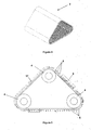
- FIG. 1 An embodiment of automated floor cleaner or cleaning robot 1 is shown in figure 1 .
- the automated floor cleaner has a cleaner body 2 on which a number of individual elements are mounted, as detailed below.
- the elements mounted on the body can be broadly divided into three main sub-groups: cleaning elements; movement elements, and; sensing elements.
- the cleaning robot 1 also contains an integral processor 20 that controls the operations of the cleaning robot 1 (sending commands to the cleaning and movement elements, and receiving feedback and data back from these), and which also receives input from the sensing elements, and external commands from operators or similar.
- the cleaner body 2 appears rectangular from above, and has a chassis 2a that forms the main part of the cleaner body, and a cover or casing 2b that is mounted to the chassis 2a and which covers and protects the other elements mounted thereon. The sides of the cover are angled inwards so that the automated floor cleaner 1 appears pyramid-shaped.
- a pair of drive wheels 7 are mounted to the chassis 2a at the front of the cleaner body 2, at or close to the front corners. Each of the pair of drive wheels 7 is powered by an electric motor 19 (one motor 19 for each of the wheels 7) that is mounted in the cleaner body 2, next to the wheel 7 that it drives.
- the motors 19 can be driven independently so as to allow the floor cleaner 1 to turn and/or corner.
- a pair of caster wheels 8 are mounted at or close to the rear corners of the cleaner body 2. These are undriven, but can rotate freely to allow the floor cleaner 1 to turn and move freely.
- a pair of 30mm caster wheels are used, but a single wheel could also be used in place of the pair, and these could be of any suitable size, for example any size in the range between 25mm and 75mm.
- the main cleaning element is an endless belt 3.
- the endless belt 3 is formed from rubber, and has a smooth inner surface, and bristles 5 formed integrally with the outer surface, which scrub the floor as the belt moves over the floor.
- the endless belt 3 and bristles 5 will be described in detail below.
- the endless belt 3 is mounted on the cleaner body 2 via three rollers 4, the belt 3 passing over the rollers 4.
- the rollers 4 are arranged so that when viewed from the side (perpendicular to the direction of travel of the belt) the belt appears as an equilateral triangle, with rounded corner where the belt passes over the rollers.
- One roller is located at the apex, and the other two form the lower corners.
- the outer surface of that section of the belt between the two lower rollers is in contact with the floor surface - that is, around 1/3 of the total outer surface area of the belt is in contact with the floor surface at any one time.
- the belt 3 continually passes over the rollers 4 in use so that the outer surface of the belt moves across and scrubs the floor.
- a motor 6 is mounted between the rollers 4 (inside the triangle of the belt 3) and drives at least one of the rollers to move the belt 3.
- the upright sides of the triangle form a front belt face and a rear belt face. The belt moves so that that portion of the belt at the front (the front belt face) moves downwards and under the cleaner body 2.
- a sponge 17 is mounted so as to be in contact with the front belt face. As the belt moves, the sponge wipes the belt, the sponge 17 remaining stationary.
- Fluid atomiser or fluid jets 9 are mounted on the cleaner body 2 at the front of the cleaner body 2.
- up to fifteen or more individual jets could be used.
- a single jet could also be used.
- the jet or jets face rearwards and downwards to direct a spray of fluid towards the front belt face so as to soak the sponge 17, which in turn wets the belt 3.
- the fluid jet or jets 9 in this embodiment can spray between 500ml and 1,500ml per hour, depending on the cleaning requirement.
- the fluid jets 9 are fluidically connected to and fed from a tank 10 that is also mounted on the cleaner body 2.
- the tank 10 holds a volume of fluid such as a cleaning fluid or water.
- the tank 10 can be replenished and refilled via a top filling aperture that in use is closed by a cap 15.
- a cleaner pump 11 drives the flow of water from the tank 10 to the jets 9.
- a vacuum pump 12 is mounted on the cleaner body 2 at the rear side of the belt 3, so as to provide a suction force onto the raised external surface of the belt 3 just after that section of the external surface area of the belt 3 moves out of contact with the floor surface, the suction force pulling fluids and particles off the belt.
- the mixture of air, water and particles pulled off the belt is directed through a particulate filter 13 behind or downstream of the vacuum pump 12.
- the particulate filter 13 removes particles from the air and water stream, and in this embodiment has a rating of five microns or above.
- the filter 13 is a carbonate sponge filter or filters. These have been found to provide a greater surface area for trapping particles within the gases/liquid stream.
- the stream is then passed through a UV filter 14, which directs UV light through the stream to kill bacteria and other pathogens. Once the stream has passed through the UV filter, it is directed back to the tank 10 via a secondary assistance pump 18.
- the endless belt 3 is one of the main cleaning elements.
- the belt 3 has a width of between 250mm and 450mm, and an overall length of 730 to 780mm. However, in most variations, it is likely that the belt will have a width of between 270mm and 300mm.
- the belt 3 is formed from rubber, the bristles 5 extending from one side of the main continuous body of the belt 3.
- the bristles 5 are formed integrally with the main body of the belt 3.
- the main continuous body of the belt 3 has a standard cross-sectional depth or thickness at any particular point. Ideally, the depth of the main continuous body of the belt 3 is between 5mm and 12mm (that is, the belt 3 has e.g. a depth of 5mm at all points along the body, or a thickness of 12mm at all points along the body, or any dimension therebetween).
- the inner side of the belt 3 is smooth so as to pass easily over the rollers 4.
- the bristles 5 are integrally formed as part of the belt 3 and extend from the other, or outer, side.
- the bristles 5 are spaced across the width of the belt 3, substantially regularly across the width of the belt, and are arranged in rows perpendicularly across the width of the belt 3.
- the number of bristles 5 in each row is between 50 and 60.
- the rows are formed in groups of six rows, each row spaced approximately 10mm from it's immediate neighbour(s) in the group, with a discrete gap between each group of approximately 15mm.
- Each bristle 5 is substantially circular in cross-section, with a diameter of substantially 2mm.
- the lower half of each bristle is angled rearwards (that is, away from the direction of travel) at an angle of approximately 45 degrees.
- the motor 6 drives the belt 3 at a speed of between 50 and 150 rpm.
- a number of sensors 16 are mounted on the cleaner body 2, and as shown in figure 2 extend through the front of the cover 2b.
- the sensors 16 are a mix of short-range sensors 16a and long range sensors 16b. In the embodiment shown and described, they are infra-red sensors configured to sense the position of the floor cleaner 1 within a location and to transmit data relating to the position to a memory module configured to map and record the position of the floor cleaner during use.
- An RFID reader 22 is also included as part of the floor cleaner 1 of this embodiment.
- the RFID reader is configured to read data from RFID tags close to the floor cleaner.
- the floor cleaner 1 also includes a wireless transmitter 23 that transmits the data received from the RFID tags to a cloud-based server, along with associated time and date information, and any other information as necessary - for example linear and square meters covered during any particular cleaning operation, the time taken, and water and chemical/cleaner usage during the cleaning operation.
- a UV lamp 21 can be mounted on the chassis 2a, aligned so that the light from the UV lamp shines onto the floor.
- the UV light from the lamp assists with sterilisation of the floor surface as it is cleaned.
- the sensors could be ultrasonic rather than infra-red, and GPS could be used instead of or as well as the proximity sensors.
- the belt of the embodiment described above is generally arranged as an equilateral triangular shape in side view.
- the belt could be arranged in other suitable shapes.
- the belt could be arranged as a right-angle or non-regular triangle shape, or with a top portion parallel to the lower or underside portion that is in contact with and extending along the floor surface, with the ends looped over a main pair of rollers - a front and rear roller. That is, the shape made by the belt would appear generally rectangular in side view, with rounded or semi-circular ends.
- the motor 6 drives the belt 3 at a speed of between 50 and 150 rpm.
- the fluid jet or jets 9 spray between 500ml and 1,500ml per hour.
- Operation of the floor cleaner 1 within a room, hall or other bounded or discrete area to be cleaned is as follows: An operator transports the floor cleaner 1 to an area to be cleaned, such as a room or a hall. Entry of the cleaner into the room is recorded via communication/transmission between RFID tags that have been pre-located in the room, and the RFID reader in the floor cleaner 1. Each of the RFID tags serves to uniquely identify the particular area. This is communicated to the floor cleaner 1 on interrogation by the RFID reader. Other information about the location can also be included in the RFID tag as required. The location information is transmitted from the floor cleaner 1 to a cloud-based server, along with time/date of operation information, and other specific cleaning information as detailed below.
- the relative directional or positional information in the following portion of the description in relation to the operation of the floor cleaner 1 should be read as if viewing a regular, rectangular room in plan view. These should not be read as directional or turn indications for the cleaning robot 1 in use, and only as direction indicators relative to the rectangular room in plan view.
- a flow chart showing the general cleaning process and decision points is shown in figure 9 . The operator locates the floor cleaner 1 at the lower-right-hand corner of the room (viewed in plan view), with the floor cleaner 1 aligned so as to travel directly in parallel with the right-hand wall (that is, vertically upwards when viewed in plan view). The floor cleaner 1 is then set in operation.
- step 100 the cleaning robot 1 will read the RFID data from the RFID tag in the room. Once this is completed, the robot will start a cleaning operation (step 101), the cleaning robot 1 moving from the initial position in the lower-right corner to travel along the floor, in parallel with the wall to it's right (upwards in plan view). As the floor cleaner 1 moves, the belt 3 rotates to scrub the floor, the fluid jets 9 spraying the front face of the belt, the floor cleaner 1 creating a cleaned track along the right-hand wall, in parallel with the wall.
- the floor cleaner 1 will continue to travel in this direction until the sensors 16 sense that it is approaching a wall or other obstacle - for example, the far wall of the room, which for a rectangular room viewed in plan view is the wall that forms the horizontal top edge of the room.
- the floor cleaner 1 is programmed to slow down as it approaches this wall. At the point at which the floor cleaner 1 reaches this far wall, it will stop in place.
- the floor cleaner 1 will stop as close in to the far wall as it can, while still being able to manoeuvre in place, with this distance measured by the sensors 16, which feed information back to the central processor 20 so that the central processor 20 can asses the distance and relative positions of the floor cleaner 1 and the wall in front of it.
- the central processor 20 judges that the floor cleaner 1 is close enough to the wall, the central processor 20 will command the floor cleaner 1 to carry out a zero-point turn, or turn/rotate in place, to it's left, or anti-clockwise. That is, the turn takes place about a vertical axis that generally passes through the apex of the pyramid formed by the casing 2b.
- the floor cleaner 1 turns anti-clockwise (viewed in plan) until it is aligned so as to move parallel to the far or top wall, to the left.
- the cleaning robot will assess whether it has reached the far-left wall of the room (decision box 201).
- box 102 represents a turn at the top edge through 180 degrees to starts a downwards track.
- box 102 represents a turn at either end of 180 degrees to face in the opposite direction.
- the processor 20 then instructs the floor cleaner 1 to move forward, and the floor cleaner 1 then moves back towards the lower edge or wall along a path next to the initial or first-created track, the cleaning path the floor cleaner 1 creates on this path overlapping with the initially created path.
- the cleaning robot will also assess whether this return track is shorter than the previous track (decision box 202). If not shorter, it will move on the assess whether it is longer (decision box 203). In this example, the room is empty, so the tracks are the same length. Therefore, on reaching the lower edge or wall, the floor cleaner 1 performs another zero-point turn to it's right, or clockwise through 90 degrees, until it can move parallel with the lower edge or wall.
- the floor cleaner 1 then moves forwards a short distance and makes another right-hand/clockwise turn so that it is facing in the same direction as it was initially facing, back towards the top edge or wall, with the track that it is about to create again overlapping the parallel adjacent track by 2-3cm.
- the floor cleaner 1 will continue to operate in this manner, moving up and down/ across the room to create a series of cleaned strips or tracks in parallel to one another and parallel to the side walls, until it reaches the left-hand wall. That is, when it turns at either the top or the bottom wall, it can move no further to the left, or can only move a shorter distance than it would normally when moving to the left.
- the cleaning robot will move to the lower-left corner (plan view), either by completing it's final track upwards along the left-hand wall, or downwards.
- the description above is for a cleaning process where the room is empty. If the room contains an obstacle of some kind, such as for example a table, desk or bed in the centre of the room, the process is outlined below.
- the relative directional or positional information should be read as if viewing the room in plan view, with all directional information for the robot relative to the room (e.g. the robot turns to the left or right in the room, not the robot's left or right).
- An operator transports the floor cleaner 1 to the room, with entry of the cleaner 1 into the room recorded via communication/transmission between RFID tags in the room, and the RFID reader in the floor cleaner 1, in the same or similar manner to that outlined above (box 100).
- the operator locates the floor cleaner 1 at the lower-right-hand corner of the room, and the processor 20 than instructs the floor cleaner 1 to move forward, the floor cleaner 1 moving forward parallel to the right-hand wall (box 101).
- the floor cleaner 1 turns and moves until it faces back towards the lower edge or wall along a path next to the initial or first-created track, with the cleaning path the floor cleaner 1 creates on this 'return' path overlapping with the initially created path in the same or similar manner to that outlined above (box 102).
- the decision path goes from box 202, to 203, to 201 and back to 102, so on reaching the lower wall, at a point directly adjacent to the start point, the robot will turn in place to the left and start upwards on a track parallel to the tracks already created, and overlapping with the track to it's immediate right.
- the floor cleaner 1 continues moving in this manner to create a series of parallel overlapping clean paths or strips until it encounters an obstacle. If the obstacle is in the approximate centre of the room (for example an operating table or other centrally located table or other item), the floor cleaner 1 will encounter either the lower edge or the upper edge on either an upwards path or a downwards path.
- the sensors 16 will indicate that there is an obstacle, and the processor 20 will instruct the floor cleaner 1 to slow down and then stop in a position as close to the obstacle as possible, while still being able to carry out a zero-point turn.
- the processor 20 will know that the floor cleaner 1 has encountered an obstacle, as the processor 20 continuously monitors and receives feedback from elements such as for example the drive motors 16, and is therefore able to assess distances and times for the parallel cleaning paths, and will therefore know that the current track or strip is shorter than the previous parallel track or strip (decision box 202). In the example shown in figure 7a , the path that the cleaning robot is on will be shorter than the previous path, on the lower side of the table or other central obstacle.
- the processor instructs the cleaning robot 1 to make turns to create parallel clean strips in the same direction - to the left - as before (box 103), along the lower side of the obstacle (the paths shown along the lower edge in figure 7a ).
- the processor 20 is able to assess the 'length' of the obstacle based on how many of the shorter paths it creates before it clears the obstacle and is able to once again create a path as long as the initial path. Once the processor 20 has assessed that the track it is currently on or has just completed is longer than it's previous track (box 204 - path longer? Y/N), it knows that it has cleared the left-hand side of the obstacle.
- the path taken by the robot to move back to this position is shown by the dotted line in figure 7a , and for clarity is shown slightly below the shorter horizontal lines which indicate the path taken by the cleaning robot 1 to track across the room between the longer parallel clean strips.
- the floor cleaner 1 will then continue to operate as previously outlined for an obstacle-free room until it reaches the left-hand wall, at which point it will clean until it is located in the lower-left corner, when it will transmit information relating to the cleaning process in a similar manner to that outlined above, and then deactivate.
- the floor cleaner 1 will move backwards and forwards (up and down in plan view) so as to create a series of short cleaned strips each of the same length, as shown in figure 7b , following the steps of boxes 100, 101 and 102 (read RFIDs, move until the far wall is reached, turn around and position for return strip in parallel to and overlapping with previous strip, to the left of previous strip.
- the processor 20 will recognise that it is creating a longer strip ('N' from decision box 202 - not shorter, and 'Y' from box 203 - strip is longer), and will know from this that it is clear of the obstacle.
- the floor cleaner 1 will turn to the right (box 105), so as to commence the creation of a series of short strips along the top of the obstacle.
- the processor can assess that the floor cleaner 1 has reached the right-hand wall by interrogating the data received from e.g.
- the cleaning robot 1 will move along the wall directly adjacent to the wall.
- the floor cleaner 1 will then continue to operate as previously outlined for an obstacle-free room until it reaches the left-hand wall, at which point it will clean until it is located in the lower-left corner, when it will transmit information relating to the cleaning process in a similar manner to that outlined above, and then deactivate.
- the processor 20 will recognise when it is creating longer or shorter strips than it has on previous runs, and will then subsequently recognise that it is either clear of an obstacle (by creating a subsequent longer run) and that it therefore needs to return to cover the opposite side of the obstacle, or that it has reached the far (left-hand) wall without creating a longer run, but that it's last strip was shorter than its initial strip(s), which indicates that there is an obstacle in the lower-left corner of the room, and that it should transmit data and deactivate.
Landscapes
- Engineering & Computer Science (AREA)
- Physics & Mathematics (AREA)
- General Physics & Mathematics (AREA)
- Aviation & Aerospace Engineering (AREA)
- Radar, Positioning & Navigation (AREA)
- Remote Sensing (AREA)
- Automation & Control Theory (AREA)
- Sustainable Development (AREA)
- Environmental & Geological Engineering (AREA)
- Plasma & Fusion (AREA)
- Life Sciences & Earth Sciences (AREA)
- Electromagnetism (AREA)
- Electric Vacuum Cleaner (AREA)
- Control Of Position, Course, Altitude, Or Attitude Of Moving Bodies (AREA)
Claims (14)
- Automatisierter Bodenreiniger (1), umfassend:einen Reinigerkörper (2);ein Bewegungsmittel (7, 19), das mit dem Reinigerkörper (2) verbunden und so ausgestaltet ist, dass sich der Bodenreiniger (1) bei Verwendung über eine Oberfläche bewegen kann;ein Erfassungsmittel (16), das ausgestaltet ist, die Position des Bodenreinigers (1) innerhalb eines Standorts zu erfassen und Daten bezüglich der Position zu einem Speichermodul (20) zu übermitteln, das ausgestaltet ist, die Position des Bodenreinigers (1) während der Verwendung zu kartieren und aufzuzeichnen;dadurch gekennzeichnet, dass der Bodenreiniger ferner Folgendes umfasst:einen Endlosriemen (3), der mit dem Reinigerkörper (2) verbunden ist und sich von ihm erstreckt, sodass ein Abschnitt des Oberflächenbereichs des Riemens (3) bei Verwendung in Kontakt mit dem Boden steht, um die Bodenfläche bei Verwendung zu reinigen;einen Motor (6), der mit dem Riemen (3) verbunden ist, um den Riemen (3) unabhängig von einer Bewegung des Bodenreinigers (1) über den Boden anzutreiben.
- Automatisierter Bodenreiniger nach Anspruch 1, wobei der Riemen eine Vielzahl von Borsten umfasst, die sich von dem Hauptkörper des Riemens nach außen erstrecken.
- Automatisierter Bodenreiniger nach Anspruch 2, wobei die Borsten über die Breite des Riemens beabstandet sind.
- Automatisierter Bodenreiniger nach Anspruch 3, wobei die Borsten über die Breite des Riemens im Wesentlichen regelmäßig in Reihen beabstandet sind, wobei die Anzahl von Borsten in jeder Reihe im Wesentlichen zwischen 50 und 60 beträgt.
- Automatisierter Bodenreiniger nach Anspruch 4, wobei die Reihen in Gruppen von sechs Reihen mit einem Einzelspalt zwischen jeder Gruppe gebildet sind.
- Automatisierter Bodenreiniger nach Anspruch 4, wobei die Reihen in jeder Gruppe im Wesentlichen 10 mm voneinander beabstandet sind.
- Automatisierter Bodenreiniger nach Anspruch 5 oder 6, wobei der Einzelspalt zwischen jeder Gruppe im Wesentlichen 15 mm beträgt.
- Automatisierter Bodenreiniger nach einem der Ansprüche 2 bis 7, wobei jede Borste im Querschnitt im Wesentlichen kreisförmig ist, mit einem Durchmesser von im Wesentlichen 2 mm.
- Automatisierter Bodenreiniger nach Anspruch 8, wobei im Wesentlichen die äußere Hälfte jeder Borste rückwärts angewinkelt ist.
- Automatisierter Bodenreiniger nach Anspruch 9, wobei der Winkel im Wesentlichen 45 Grad beträgt.
- Automatisierter Bodenreiniger nach einem der Ansprüche 1 bis 10, wobei der Riemen eine Breite von im Wesentlichen zwischen 250 mm und 450 mm aufweist.
- Automatisierter Bodenreiniger nach einem der Ansprüche 1 bis 11, wobei der Hauptkörper des Riemens eine Dicke von im Wesentlichen zwischen 5 mm und 12 mm aufweist.
- Automatisierter Bodenreiniger nach einem der Ansprüche 1 bis 12, wobei der Riemen so angeordnet ist, dass er sich bei Verwendung von dem Reinigerkörper erstreckt, sodass der Abschnitt des Oberflächenbereichs des Riemens, der sich in Kontakt mit dem Boden befindet, im Wesentlichen zwischen 1/3 und 1/2 des gesamten äußeren Oberflächenbereichs des Riemens umfasst.
- Automatisierter Bodenreiniger nach einem der Ansprüche 1 bis 13, wobei ein Reinigungsmittel mit dem Reinigerkörper verbunden und ausgestaltet ist, bei Verwendung in Kontakt mit einer Bodenoberfläche zu stehen, um die Oberfläche zu reinigen, wobei das Reinigungsmittel mindestens zwei Rollen umfasst und wobei die Rollen und der Riemen so angeordnet sind, dass der Riemen über den Rollen verläuft und gespannt gehalten wird.
Applications Claiming Priority (2)
| Application Number | Priority Date | Filing Date | Title |
|---|---|---|---|
| GBGB1510373.2A GB201510373D0 (en) | 2015-06-12 | 2015-06-12 | An automated floor cleaner |
| PCT/GB2016/000115 WO2016198822A1 (en) | 2015-06-12 | 2016-06-07 | An automated floor cleaner |
Publications (2)
| Publication Number | Publication Date |
|---|---|
| EP3307128A1 EP3307128A1 (de) | 2018-04-18 |
| EP3307128B1 true EP3307128B1 (de) | 2019-11-06 |
Family
ID=53784663
Family Applications (1)
| Application Number | Title | Priority Date | Filing Date |
|---|---|---|---|
| EP16729610.2A Active EP3307128B1 (de) | 2015-06-12 | 2016-06-07 | Automatisierter bodenreiniger |
Country Status (4)
| Country | Link |
|---|---|
| US (1) | US10555656B2 (de) |
| EP (1) | EP3307128B1 (de) |
| GB (1) | GB201510373D0 (de) |
| WO (1) | WO2016198822A1 (de) |
Cited By (1)
| Publication number | Priority date | Publication date | Assignee | Title |
|---|---|---|---|---|
| CN111449575A (zh) * | 2020-04-22 | 2020-07-28 | 陈志湘 | 一种口腔科用滤气吸污机 |
Families Citing this family (14)
| Publication number | Priority date | Publication date | Assignee | Title |
|---|---|---|---|---|
| TWI634403B (zh) * | 2017-01-26 | 2018-09-01 | 好樣科技有限公司 | 自動清潔機及其控制方法 |
| US10820772B2 (en) | 2017-09-15 | 2020-11-03 | Omachron Intellectual Property Inc. | Surface cleaning apparatus |
| US12459720B2 (en) | 2017-09-15 | 2025-11-04 | Omachron Intellectual Property Inc. | Non-cyclonic momentum separator and a surface cleaning apparatus |
| AU2019248254A1 (en) * | 2018-04-06 | 2020-11-26 | Lg Electronics Inc. | Mobile robot and mobile robot system |
| KR102249808B1 (ko) | 2018-04-06 | 2021-05-10 | 엘지전자 주식회사 | 이동 로봇 시스템 및 이동 로봇 시스템의 제어 방법 |
| GB2576494B (en) | 2018-08-06 | 2022-03-23 | Dyson Technology Ltd | A mobile robot and method of controlling thereof |
| CN111493743B (zh) * | 2019-01-31 | 2022-03-08 | 好样科技有限公司 | 清洁机及清洁机的路径规划方法 |
| US11553823B2 (en) | 2019-08-02 | 2023-01-17 | International Business Machines Corporation | Leveraging spatial scanning data of autonomous robotic devices |
| CN112720451B (zh) * | 2019-10-28 | 2021-12-03 | 深圳市行知行机器人技术有限公司 | 自动作业机器人及其按规划路径自动作业的控制方法 |
| TWI722641B (zh) * | 2019-11-07 | 2021-03-21 | 福機裝股份有限公司 | 自動清潔裝置 |
| CA3105484A1 (en) * | 2020-01-10 | 2021-07-10 | Bissell Inc. | Autonomous floor cleaner and method for autonomous floor cleaning |
| SE2150497A1 (en) * | 2021-04-22 | 2022-10-23 | Husqvarna Ab | Improved obstacle handling for a robotic work tool |
| CN115919207B (zh) * | 2021-08-17 | 2025-09-02 | 美智纵横科技有限责任公司 | 一种滚刷装置以及机器人 |
| EP4400014A1 (de) * | 2023-01-11 | 2024-07-17 | Versuni Holding B.V. | Feuchtreinigungsgerät und verfahren zu dessen betrieb |
Family Cites Families (6)
| Publication number | Priority date | Publication date | Assignee | Title |
|---|---|---|---|---|
| KR100483548B1 (ko) * | 2002-07-26 | 2005-04-15 | 삼성광주전자 주식회사 | 로봇 청소기와 그 시스템 및 제어 방법 |
| US20050209736A1 (en) | 2002-11-13 | 2005-09-22 | Figla Co., Ltd. | Self-propelled working robot |
| JP2005211499A (ja) | 2004-01-30 | 2005-08-11 | Funai Electric Co Ltd | 自走式掃除機 |
| JP3832593B2 (ja) * | 2004-03-25 | 2006-10-11 | 船井電機株式会社 | 自走式掃除機 |
| CN104248395B (zh) | 2008-04-24 | 2018-06-22 | 艾罗伯特公司 | 用于机器人使能的移动产品的定位、位置控制和导航系统的应用 |
| PL394570A1 (pl) * | 2011-04-15 | 2012-10-22 | Robotics Inventions Spólka Z Ograniczona Odpowiedzialnoscia | Robot do podlóg podniesionych i sposób serwisowania podlóg podniesionych |
-
2015
- 2015-06-12 GB GBGB1510373.2A patent/GB201510373D0/en not_active Ceased
-
2016
- 2016-06-07 US US15/580,171 patent/US10555656B2/en active Active
- 2016-06-07 EP EP16729610.2A patent/EP3307128B1/de active Active
- 2016-06-07 WO PCT/GB2016/000115 patent/WO2016198822A1/en not_active Ceased
Non-Patent Citations (1)
| Title |
|---|
| None * |
Cited By (1)
| Publication number | Priority date | Publication date | Assignee | Title |
|---|---|---|---|---|
| CN111449575A (zh) * | 2020-04-22 | 2020-07-28 | 陈志湘 | 一种口腔科用滤气吸污机 |
Also Published As
| Publication number | Publication date |
|---|---|
| US20180140155A1 (en) | 2018-05-24 |
| GB201510373D0 (en) | 2015-07-29 |
| WO2016198822A1 (en) | 2016-12-15 |
| EP3307128A1 (de) | 2018-04-18 |
| US10555656B2 (en) | 2020-02-11 |
Similar Documents
| Publication | Publication Date | Title |
|---|---|---|
| EP3307128B1 (de) | Automatisierter bodenreiniger | |
| US11376341B2 (en) | Sanitization and cleaning system for objects | |
| US9510715B2 (en) | Robotic vacuum cleaning | |
| CN102083352B (zh) | 用于机器人使能的移动产品的定位、位置控制和导航系统的应用 | |
| JP4542044B2 (ja) | 自律機械 | |
| US10368708B2 (en) | Household robot and method for operating a household robot | |
| US8774970B2 (en) | Trainable multi-mode floor cleaning device | |
| US20250302264A1 (en) | Robotic systems and methods | |
| US10219665B2 (en) | Robotic vacuum cleaner with protruding sidebrush | |
| NL1026023C2 (nl) | Robotreiniger met vloerdesinfecterende functie. | |
| KR102145915B1 (ko) | 살균 기능을 갖는 청소기 | |
| WO2014039076A1 (en) | Robotic room sanitizer | |
| US12478240B2 (en) | Method of controlling a robotic floor cleaning machine | |
| WO2015115889A1 (en) | Method and device for cleaning cubicles | |
| WO2023212871A1 (en) | Robotic systems and methods | |
| EP3903837B1 (de) | Bodenreinigungs- und desinfektionssystem | |
| TW202306522A (zh) | 自動化機器人消毒系統 | |
| Elkmann et al. | Cleaning automation | |
| JP2009207790A (ja) | 拭き取り清掃を行う自走式掃除機 | |
| JPH01293837A (ja) | 清掃ロボット | |
| WO2025202925A1 (en) | Autonomous robot and method for cleaning sensor comprised in autonomous robot | |
| KR20230028676A (ko) | 자주식 모듈을 이용한 침대 토탈관리 시스템 |
Legal Events
| Date | Code | Title | Description |
|---|---|---|---|
| STAA | Information on the status of an ep patent application or granted ep patent |
Free format text: STATUS: THE INTERNATIONAL PUBLICATION HAS BEEN MADE |
|
| PUAI | Public reference made under article 153(3) epc to a published international application that has entered the european phase |
Free format text: ORIGINAL CODE: 0009012 |
|
| STAA | Information on the status of an ep patent application or granted ep patent |
Free format text: STATUS: REQUEST FOR EXAMINATION WAS MADE |
|
| 17P | Request for examination filed |
Effective date: 20180112 |
|
| AK | Designated contracting states |
Kind code of ref document: A1 Designated state(s): AL AT BE BG CH CY CZ DE DK EE ES FI FR GB GR HR HU IE IS IT LI LT LU LV MC MK MT NL NO PL PT RO RS SE SI SK SM TR |
|
| AX | Request for extension of the european patent |
Extension state: BA ME |
|
| DAV | Request for validation of the european patent (deleted) | ||
| DAX | Request for extension of the european patent (deleted) | ||
| STAA | Information on the status of an ep patent application or granted ep patent |
Free format text: STATUS: EXAMINATION IS IN PROGRESS |
|
| 17Q | First examination report despatched |
Effective date: 20181016 |
|
| GRAP | Despatch of communication of intention to grant a patent |
Free format text: ORIGINAL CODE: EPIDOSNIGR1 |
|
| STAA | Information on the status of an ep patent application or granted ep patent |
Free format text: STATUS: GRANT OF PATENT IS INTENDED |
|
| INTG | Intention to grant announced |
Effective date: 20190404 |
|
| GRAJ | Information related to disapproval of communication of intention to grant by the applicant or resumption of examination proceedings by the epo deleted |
Free format text: ORIGINAL CODE: EPIDOSDIGR1 |
|
| STAA | Information on the status of an ep patent application or granted ep patent |
Free format text: STATUS: EXAMINATION IS IN PROGRESS |
|
| GRAS | Grant fee paid |
Free format text: ORIGINAL CODE: EPIDOSNIGR3 |
|
| STAA | Information on the status of an ep patent application or granted ep patent |
Free format text: STATUS: GRANT OF PATENT IS INTENDED |
|
| GRAP | Despatch of communication of intention to grant a patent |
Free format text: ORIGINAL CODE: EPIDOSNIGR1 |
|
| INTC | Intention to grant announced (deleted) | ||
| INTG | Intention to grant announced |
Effective date: 20190902 |
|
| GRAA | (expected) grant |
Free format text: ORIGINAL CODE: 0009210 |
|
| STAA | Information on the status of an ep patent application or granted ep patent |
Free format text: STATUS: THE PATENT HAS BEEN GRANTED |
|
| AK | Designated contracting states |
Kind code of ref document: B1 Designated state(s): AL AT BE BG CH CY CZ DE DK EE ES FI FR GB GR HR HU IE IS IT LI LT LU LV MC MK MT NL NO PL PT RO RS SE SI SK SM TR |
|
| REG | Reference to a national code |
Ref country code: GB Ref legal event code: FG4D |
|
| REG | Reference to a national code |
Ref country code: CH Ref legal event code: EP Ref country code: AT Ref legal event code: REF Ref document number: 1197647 Country of ref document: AT Kind code of ref document: T Effective date: 20191115 |
|
| REG | Reference to a national code |
Ref country code: IE Ref legal event code: FG4D |
|
| REG | Reference to a national code |
Ref country code: DE Ref legal event code: R096 Ref document number: 602016023780 Country of ref document: DE |
|
| REG | Reference to a national code |
Ref country code: NL Ref legal event code: FP |
|
| REG | Reference to a national code |
Ref country code: LT Ref legal event code: MG4D |
|
| PG25 | Lapsed in a contracting state [announced via postgrant information from national office to epo] |
Ref country code: PL Free format text: LAPSE BECAUSE OF FAILURE TO SUBMIT A TRANSLATION OF THE DESCRIPTION OR TO PAY THE FEE WITHIN THE PRESCRIBED TIME-LIMIT Effective date: 20191106 Ref country code: SE Free format text: LAPSE BECAUSE OF FAILURE TO SUBMIT A TRANSLATION OF THE DESCRIPTION OR TO PAY THE FEE WITHIN THE PRESCRIBED TIME-LIMIT Effective date: 20191106 Ref country code: LT Free format text: LAPSE BECAUSE OF FAILURE TO SUBMIT A TRANSLATION OF THE DESCRIPTION OR TO PAY THE FEE WITHIN THE PRESCRIBED TIME-LIMIT Effective date: 20191106 Ref country code: FI Free format text: LAPSE BECAUSE OF FAILURE TO SUBMIT A TRANSLATION OF THE DESCRIPTION OR TO PAY THE FEE WITHIN THE PRESCRIBED TIME-LIMIT Effective date: 20191106 Ref country code: BG Free format text: LAPSE BECAUSE OF FAILURE TO SUBMIT A TRANSLATION OF THE DESCRIPTION OR TO PAY THE FEE WITHIN THE PRESCRIBED TIME-LIMIT Effective date: 20200206 Ref country code: GR Free format text: LAPSE BECAUSE OF FAILURE TO SUBMIT A TRANSLATION OF THE DESCRIPTION OR TO PAY THE FEE WITHIN THE PRESCRIBED TIME-LIMIT Effective date: 20200207 Ref country code: LV Free format text: LAPSE BECAUSE OF FAILURE TO SUBMIT A TRANSLATION OF THE DESCRIPTION OR TO PAY THE FEE WITHIN THE PRESCRIBED TIME-LIMIT Effective date: 20191106 Ref country code: NO Free format text: LAPSE BECAUSE OF FAILURE TO SUBMIT A TRANSLATION OF THE DESCRIPTION OR TO PAY THE FEE WITHIN THE PRESCRIBED TIME-LIMIT Effective date: 20200206 Ref country code: PT Free format text: LAPSE BECAUSE OF FAILURE TO SUBMIT A TRANSLATION OF THE DESCRIPTION OR TO PAY THE FEE WITHIN THE PRESCRIBED TIME-LIMIT Effective date: 20200306 |
|
| PG25 | Lapsed in a contracting state [announced via postgrant information from national office to epo] |
Ref country code: RS Free format text: LAPSE BECAUSE OF FAILURE TO SUBMIT A TRANSLATION OF THE DESCRIPTION OR TO PAY THE FEE WITHIN THE PRESCRIBED TIME-LIMIT Effective date: 20191106 Ref country code: HR Free format text: LAPSE BECAUSE OF FAILURE TO SUBMIT A TRANSLATION OF THE DESCRIPTION OR TO PAY THE FEE WITHIN THE PRESCRIBED TIME-LIMIT Effective date: 20191106 Ref country code: IS Free format text: LAPSE BECAUSE OF FAILURE TO SUBMIT A TRANSLATION OF THE DESCRIPTION OR TO PAY THE FEE WITHIN THE PRESCRIBED TIME-LIMIT Effective date: 20200306 |
|
| PG25 | Lapsed in a contracting state [announced via postgrant information from national office to epo] |
Ref country code: AL Free format text: LAPSE BECAUSE OF FAILURE TO SUBMIT A TRANSLATION OF THE DESCRIPTION OR TO PAY THE FEE WITHIN THE PRESCRIBED TIME-LIMIT Effective date: 20191106 |
|
| PG25 | Lapsed in a contracting state [announced via postgrant information from national office to epo] |
Ref country code: CZ Free format text: LAPSE BECAUSE OF FAILURE TO SUBMIT A TRANSLATION OF THE DESCRIPTION OR TO PAY THE FEE WITHIN THE PRESCRIBED TIME-LIMIT Effective date: 20191106 Ref country code: RO Free format text: LAPSE BECAUSE OF FAILURE TO SUBMIT A TRANSLATION OF THE DESCRIPTION OR TO PAY THE FEE WITHIN THE PRESCRIBED TIME-LIMIT Effective date: 20191106 Ref country code: EE Free format text: LAPSE BECAUSE OF FAILURE TO SUBMIT A TRANSLATION OF THE DESCRIPTION OR TO PAY THE FEE WITHIN THE PRESCRIBED TIME-LIMIT Effective date: 20191106 Ref country code: DK Free format text: LAPSE BECAUSE OF FAILURE TO SUBMIT A TRANSLATION OF THE DESCRIPTION OR TO PAY THE FEE WITHIN THE PRESCRIBED TIME-LIMIT Effective date: 20191106 |
|
| REG | Reference to a national code |
Ref country code: DE Ref legal event code: R097 Ref document number: 602016023780 Country of ref document: DE |
|
| REG | Reference to a national code |
Ref country code: AT Ref legal event code: MK05 Ref document number: 1197647 Country of ref document: AT Kind code of ref document: T Effective date: 20191106 |
|
| PG25 | Lapsed in a contracting state [announced via postgrant information from national office to epo] |
Ref country code: SK Free format text: LAPSE BECAUSE OF FAILURE TO SUBMIT A TRANSLATION OF THE DESCRIPTION OR TO PAY THE FEE WITHIN THE PRESCRIBED TIME-LIMIT Effective date: 20191106 Ref country code: SM Free format text: LAPSE BECAUSE OF FAILURE TO SUBMIT A TRANSLATION OF THE DESCRIPTION OR TO PAY THE FEE WITHIN THE PRESCRIBED TIME-LIMIT Effective date: 20191106 |
|
| PLBE | No opposition filed within time limit |
Free format text: ORIGINAL CODE: 0009261 |
|
| STAA | Information on the status of an ep patent application or granted ep patent |
Free format text: STATUS: NO OPPOSITION FILED WITHIN TIME LIMIT |
|
| 26N | No opposition filed |
Effective date: 20200807 |
|
| PG25 | Lapsed in a contracting state [announced via postgrant information from national office to epo] |
Ref country code: ES Free format text: LAPSE BECAUSE OF FAILURE TO SUBMIT A TRANSLATION OF THE DESCRIPTION OR TO PAY THE FEE WITHIN THE PRESCRIBED TIME-LIMIT Effective date: 20191106 |
|
| PG25 | Lapsed in a contracting state [announced via postgrant information from national office to epo] |
Ref country code: AT Free format text: LAPSE BECAUSE OF FAILURE TO SUBMIT A TRANSLATION OF THE DESCRIPTION OR TO PAY THE FEE WITHIN THE PRESCRIBED TIME-LIMIT Effective date: 20191106 Ref country code: SI Free format text: LAPSE BECAUSE OF FAILURE TO SUBMIT A TRANSLATION OF THE DESCRIPTION OR TO PAY THE FEE WITHIN THE PRESCRIBED TIME-LIMIT Effective date: 20191106 |
|
| PG25 | Lapsed in a contracting state [announced via postgrant information from national office to epo] |
Ref country code: IT Free format text: LAPSE BECAUSE OF FAILURE TO SUBMIT A TRANSLATION OF THE DESCRIPTION OR TO PAY THE FEE WITHIN THE PRESCRIBED TIME-LIMIT Effective date: 20191106 Ref country code: MC Free format text: LAPSE BECAUSE OF FAILURE TO SUBMIT A TRANSLATION OF THE DESCRIPTION OR TO PAY THE FEE WITHIN THE PRESCRIBED TIME-LIMIT Effective date: 20191106 |
|
| PG25 | Lapsed in a contracting state [announced via postgrant information from national office to epo] |
Ref country code: LU Free format text: LAPSE BECAUSE OF NON-PAYMENT OF DUE FEES Effective date: 20200607 |
|
| REG | Reference to a national code |
Ref country code: BE Ref legal event code: MM Effective date: 20200630 |
|
| PG25 | Lapsed in a contracting state [announced via postgrant information from national office to epo] |
Ref country code: BE Free format text: LAPSE BECAUSE OF NON-PAYMENT OF DUE FEES Effective date: 20200630 |
|
| PG25 | Lapsed in a contracting state [announced via postgrant information from national office to epo] |
Ref country code: TR Free format text: LAPSE BECAUSE OF FAILURE TO SUBMIT A TRANSLATION OF THE DESCRIPTION OR TO PAY THE FEE WITHIN THE PRESCRIBED TIME-LIMIT Effective date: 20191106 Ref country code: MT Free format text: LAPSE BECAUSE OF FAILURE TO SUBMIT A TRANSLATION OF THE DESCRIPTION OR TO PAY THE FEE WITHIN THE PRESCRIBED TIME-LIMIT Effective date: 20191106 Ref country code: CY Free format text: LAPSE BECAUSE OF FAILURE TO SUBMIT A TRANSLATION OF THE DESCRIPTION OR TO PAY THE FEE WITHIN THE PRESCRIBED TIME-LIMIT Effective date: 20191106 |
|
| PG25 | Lapsed in a contracting state [announced via postgrant information from national office to epo] |
Ref country code: MK Free format text: LAPSE BECAUSE OF FAILURE TO SUBMIT A TRANSLATION OF THE DESCRIPTION OR TO PAY THE FEE WITHIN THE PRESCRIBED TIME-LIMIT Effective date: 20191106 |
|
| P01 | Opt-out of the competence of the unified patent court (upc) registered |
Effective date: 20230613 |
|
| PGFP | Annual fee paid to national office [announced via postgrant information from national office to epo] |
Ref country code: DE Payment date: 20250626 Year of fee payment: 10 |
|
| PGFP | Annual fee paid to national office [announced via postgrant information from national office to epo] |
Ref country code: GB Payment date: 20250512 Year of fee payment: 10 |
|
| PGFP | Annual fee paid to national office [announced via postgrant information from national office to epo] |
Ref country code: NL Payment date: 20250624 Year of fee payment: 10 |
|
| PGFP | Annual fee paid to national office [announced via postgrant information from national office to epo] |
Ref country code: FR Payment date: 20250624 Year of fee payment: 10 |
|
| PGFP | Annual fee paid to national office [announced via postgrant information from national office to epo] |
Ref country code: IE Payment date: 20250617 Year of fee payment: 10 |
|
| PGFP | Annual fee paid to national office [announced via postgrant information from national office to epo] |
Ref country code: CH Payment date: 20250701 Year of fee payment: 10 |