EP3306838A1 - System und verfahren zum testen von gruppenantennen - Google Patents
System und verfahren zum testen von gruppenantennen Download PDFInfo
- Publication number
- EP3306838A1 EP3306838A1 EP16199018.9A EP16199018A EP3306838A1 EP 3306838 A1 EP3306838 A1 EP 3306838A1 EP 16199018 A EP16199018 A EP 16199018A EP 3306838 A1 EP3306838 A1 EP 3306838A1
- Authority
- EP
- European Patent Office
- Prior art keywords
- signal paths
- signal
- probe
- test
- measurement device
- Prior art date
- Legal status (The legal status is an assumption and is not a legal conclusion. Google has not performed a legal analysis and makes no representation as to the accuracy of the status listed.)
- Granted
Links
- 238000012360 testing method Methods 0.000 title claims abstract description 77
- 238000000034 method Methods 0.000 title claims description 19
- 238000003491 array Methods 0.000 title description 6
- 238000005259 measurement Methods 0.000 claims abstract description 45
- 239000000523 sample Substances 0.000 claims abstract description 28
- 239000011159 matrix material Substances 0.000 claims description 11
- 238000004891 communication Methods 0.000 description 4
- 238000010586 diagram Methods 0.000 description 3
- 230000007423 decrease Effects 0.000 description 2
- 230000001934 delay Effects 0.000 description 2
- 230000003111 delayed effect Effects 0.000 description 2
- 230000001419 dependent effect Effects 0.000 description 1
- 238000011161 development Methods 0.000 description 1
- 230000018109 developmental process Effects 0.000 description 1
- 230000007774 longterm Effects 0.000 description 1
Images


Classifications
-
- H—ELECTRICITY
- H04—ELECTRIC COMMUNICATION TECHNIQUE
- H04B—TRANSMISSION
- H04B17/00—Monitoring; Testing
-
- H—ELECTRICITY
- H04—ELECTRIC COMMUNICATION TECHNIQUE
- H04B—TRANSMISSION
- H04B17/00—Monitoring; Testing
- H04B17/10—Monitoring; Testing of transmitters
- H04B17/11—Monitoring; Testing of transmitters for calibration
- H04B17/12—Monitoring; Testing of transmitters for calibration of transmit antennas, e.g. of the amplitude or phase
-
- G—PHYSICS
- G01—MEASURING; TESTING
- G01R—MEASURING ELECTRIC VARIABLES; MEASURING MAGNETIC VARIABLES
- G01R29/00—Arrangements for measuring or indicating electric quantities not covered by groups G01R19/00 - G01R27/00
- G01R29/08—Measuring electromagnetic field characteristics
- G01R29/10—Radiation diagrams of antennas
-
- H—ELECTRICITY
- H04—ELECTRIC COMMUNICATION TECHNIQUE
- H04B—TRANSMISSION
- H04B17/00—Monitoring; Testing
- H04B17/10—Monitoring; Testing of transmitters
- H04B17/101—Monitoring; Testing of transmitters for measurement of specific parameters of the transmitter or components thereof
- H04B17/102—Power radiated at antenna
-
- H—ELECTRICITY
- H04—ELECTRIC COMMUNICATION TECHNIQUE
- H04B—TRANSMISSION
- H04B17/00—Monitoring; Testing
- H04B17/10—Monitoring; Testing of transmitters
- H04B17/11—Monitoring; Testing of transmitters for calibration
-
- H—ELECTRICITY
- H04—ELECTRIC COMMUNICATION TECHNIQUE
- H04B—TRANSMISSION
- H04B17/00—Monitoring; Testing
- H04B17/30—Monitoring; Testing of propagation channels
- H04B17/309—Measuring or estimating channel quality parameters
- H04B17/364—Delay profiles
-
- H—ELECTRICITY
- H04—ELECTRIC COMMUNICATION TECHNIQUE
- H04B—TRANSMISSION
- H04B7/00—Radio transmission systems, i.e. using radiation field
- H04B7/02—Diversity systems; Multi-antenna system, i.e. transmission or reception using multiple antennas
- H04B7/04—Diversity systems; Multi-antenna system, i.e. transmission or reception using multiple antennas using two or more spaced independent antennas
- H04B7/0413—MIMO systems
-
- H—ELECTRICITY
- H04—ELECTRIC COMMUNICATION TECHNIQUE
- H04L—TRANSMISSION OF DIGITAL INFORMATION, e.g. TELEGRAPHIC COMMUNICATION
- H04L43/00—Arrangements for monitoring or testing data switching networks
- H04L43/12—Network monitoring probes
-
- H—ELECTRICITY
- H04—ELECTRIC COMMUNICATION TECHNIQUE
- H04B—TRANSMISSION
- H04B17/00—Monitoring; Testing
- H04B17/0082—Monitoring; Testing using service channels; using auxiliary channels
- H04B17/0085—Monitoring; Testing using service channels; using auxiliary channels using test signal generators
Definitions
- the invention relates to a system and a method for testing antenna arrays.
- the inventive system and method can be used for calibrating such antenna arrays.
- MIMO Multiple Input Multiple Output
- LTE Long Term Evolution
- US 2016/0269093 A1 discloses a communication method and apparatus using analog and digital beamforming with respect to MIMO. Nevertheless, the aforementioned document does not consider testing or calibrating an antenna array, which is essential for ensuring the proper functioning of the device under test, respectively the wireless communication.
- a system for testing and/or calibrating an antenna array comprises a device under test comprising the antenna array and at least one active radio frequency device for transmitting a test signal being known and always the same or at least partially the same on each of at least two signal paths, and a measurement device comprising at least one probe for receiving the test signal on each of the at least two signal paths.
- said test signal is advantageously a non-repeatable one at least for the time of testing and/or calibrating.
- At least one of amplitude, frequency, phase and spatial dependency changes over time.
- each of the at least two signal paths is unambiguously identifiable.
- the respective signal running from the at least one active radio frequency device to the corresponding antenna is delayed, wherein this delay may not be constant in comparison with the other signal paths.
- the test signal is a chirp signal.
- the at least one probe measures the output of each of the at least two signal paths at a defined time interval.
- the measurement device collects the measurement data with respect to each of the at least two signal paths.
- the measurement device measures the time needed for changing with the position of the at least one probe from one of the at least two signal paths to another one of the at least two signal paths.
- the measurement device calculates the phase of each of the at least two signal paths and/or the phase difference between each pair of the at least two signal paths and/or the amplitude of each of at least two signal paths and/or the amplitude difference between each pair of the at least two signal paths. In other words, this calculation is performed based on measured data with respect to the output of each of the at least two signal paths, time needed for changing with position of the at least one probe from one of the at least two signal paths to another one of the at least two signal paths, and time interval for measurement of each of the at least two signal paths.
- each signal of at least one pair of the at least two signal paths partially or completely comprises the same signal portions.
- the system further comprises a switch matrix for changing the position of the at least one probe from one of the at least two signal paths to another one of the at least two signal paths.
- a method for testing and/or calibrating an antenna array uses a device under test comprising the antenna array and at least one active radio frequency device and a measurement device comprising at least one probe. Furthermore, the method comprises the steps of transmitting a test signal being known and always the same or at least partially the same on each of at least two signal paths from the device under test, and receiving the test signal on each of the at least two signal paths with the aid of the at least one probe of the measurement device.
- the test signal is a non-repeatable one at least for the time of testing and/or calibrating.
- At least one of amplitude, frequency, phase and spatial dependency changes over time.
- each of the at least two signal paths is unambiguously identifiable.
- the respective signal running from the at least one active radio frequency device to the corresponding antenna is delayed, wherein this delay may not be constant in comparison with the other signal paths.
- the test signal is a chirp signal.
- the at least one probe measures the output of each of the at least two signal paths at a defined time interval.
- the measurement device collects the measurement data with respect to each of the at least two signal paths.
- the measurement device measures the time needed for changing with position of the at least one probe from one of the at least two signal paths to another one of the at least two signal paths.
- the measurement device calculates the phase of each of the at least two signal paths and/or the phase difference between each pair of the at least two signal paths. In other words, this calculation is performed based on measured data with respect to the output of each of the at least two signal paths, time needed for changing with position of the at least one probe from one of the at least two signal paths to another one of the at least two signal paths, and time interval for measurement of each of the at least two signal paths.
- each signal of at least one pair of the at least two signal paths partially or completely comprises the same signal portions.
- the system 100 comprises a device under test 1 comprising an antenna array 4, a measurement device 2, preferably a vector network analyzer, comprising a probe 3, and a switch matrix 5.
- the antenna array 4 of the device under test 1 consists of four antennas 4a, 4b, 4c, 4d, which leads to four signal paths, each of which comprises an active radio frequency device 6a, 6b, 6c, 6d, exemplarily a transceiver, an amplifier 7a, 7b, 7c, 7d, and a bandpass 8a, 8b, 8c, 8d.
- each of the antennas 4a, 4b, 4c, 4d of the antenna array 4 of the device under test 1 is connected to the switch matrix 5 coupled to the probe 3 which is connected to the measurement device 2, respectively to the vector network analyzer.
- switching between the signal paths for testing and/or calibrating the antenna array 4 is achieved without changing the physical position of the probe 3.
- a test signal is transmitted on each of the four signal paths.
- said test signal is known, always the same, and a non-repeatable one, preferably a chirp signal or a kind thereof.
- at least one of amplitude, frequency, and phase changes over time.
- the probe 3 measures the output of each of the four signal paths with the aid of the switch matrix 5 at a defined time interval.
- the non-repeatable test signal may be fed into each of the active radio frequency devices 6a, 6b, 6c, 6d, respectively into the transceivers, by the switch matrix 5 itself via connection 9.
- the non-repeatable test signal can be transmitted via a rather low speed connection. Therefore, a cost-intensive implementation of radio frequency ports at the device under test are advantageously not necessary.
- connection 9 between the switch matrix 5 and the transceivers 6a, 6b, 6c, 6d may be an imaginary connection, which advantageously leads to the fact that an electrical connection to the device under test 1 is not required, and thus testing and/or calibrating the antenna array 4 of the device under test 1 is most time-saving and cost-efficient.
- test signal is directly implemented into the device under test 1 with the aid of hardware and/or software. Due to the fact that the test signal is known, always the same, and a non-repeatable one, the trigger condition, respectively the absolute time basis, can then be calculated with the aid of the switch matrix 5 or with the aid of the measurement device 2 or the combination thereof.
- the measurement device 2 collects the corresponding measurement data, wherein the measurement device 2 also measures the time needed for changing with the position of the probe 3 from one of the signal paths to another one of the signal path, respectively the time needed for switching between the signal paths with the aid of the switch matrix 5.
- the antennas of the antenna array can be grouped into different groups, wherein the number of groups is preferably equal to the number of input ports, respectively to the number of probes, of the measurement device.
- the number of groups is preferably equal to the number of input ports, respectively to the number of probes, of the measurement device.
- the measurement device 2 calculates the phase of each of the signal paths and/or the phase difference between each pair of the signal paths.
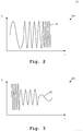
- an amplitude-time diagram 200 of an exemplary test signal 20 is shown.
- a signal is also known as a chirp signal, especially a positive chirp signal due to the increasing frequency.
- Fig. 3 illustrates an amplitude-time diagram 300 of another exemplary test signal 30.
- the Amplitude A decreases over time t
- the frequency of the exemplary test signal 30 also decreases over time t.
- the test signal 30 is a kind of a negative chirp signal.
- Fig. 4 shows a flow chart 400 of the inventive method.
- a device under test comprising an antenna array and at least one active radio frequency device, and a measurement device comprising at least one probe are provided.
- a non-repeatable test signal is transmitted on each of at least two signal paths from the device under test.
- the test signal on each of the at least two signal paths is received with the aid of the at least one probe of the measurement device.
Landscapes
- Physics & Mathematics (AREA)
- Engineering & Computer Science (AREA)
- Computer Networks & Wireless Communication (AREA)
- Signal Processing (AREA)
- Electromagnetism (AREA)
- General Physics & Mathematics (AREA)
- Quality & Reliability (AREA)
- Variable-Direction Aerials And Aerial Arrays (AREA)
- Radio Transmission System (AREA)
Priority Applications (2)
| Application Number | Priority Date | Filing Date | Title |
|---|---|---|---|
| US15/400,314 US10079646B2 (en) | 2016-10-06 | 2017-01-06 | System and method for testing antenna arrays |
| CN201710011102.7A CN107919922B (zh) | 2016-10-06 | 2017-01-06 | 用于测试天线阵列的系统和方法 |
Applications Claiming Priority (1)
| Application Number | Priority Date | Filing Date | Title |
|---|---|---|---|
| EP16192520 | 2016-10-06 |
Publications (3)
| Publication Number | Publication Date |
|---|---|
| EP3306838A1 true EP3306838A1 (de) | 2018-04-11 |
| EP3306838B1 EP3306838B1 (de) | 2019-04-03 |
| EP3306838B8 EP3306838B8 (de) | 2019-06-05 |
Family
ID=57103897
Family Applications (1)
| Application Number | Title | Priority Date | Filing Date |
|---|---|---|---|
| EP16199018.9A Active EP3306838B8 (de) | 2016-10-06 | 2016-11-16 | System und verfahren zum testen von gruppenantennen |
Country Status (3)
| Country | Link |
|---|---|
| US (1) | US10079646B2 (de) |
| EP (1) | EP3306838B8 (de) |
| CN (1) | CN107919922B (de) |
Cited By (1)
| Publication number | Priority date | Publication date | Assignee | Title |
|---|---|---|---|---|
| CN115102640A (zh) * | 2022-06-21 | 2022-09-23 | 深圳市易飞扬通信技术有限公司 | 产品测试方法、装置、计算机设备和存储介质 |
Families Citing this family (3)
| Publication number | Priority date | Publication date | Assignee | Title |
|---|---|---|---|---|
| CN109150331B (zh) * | 2018-06-15 | 2021-05-11 | 上海卫星工程研究所 | 一种卫星多数传通道指标并行自动化测试系统 |
| CN111371513B (zh) * | 2018-12-26 | 2024-04-09 | 是德科技股份有限公司 | 用于测试待测设备的天线阵列的方法及测试系统 |
| EP3748374B8 (de) * | 2019-06-06 | 2023-02-15 | Rohde & Schwarz GmbH & Co. KG | System und verfahren zur kalibrierung von funkfrequenz-testkammern |
Citations (4)
| Publication number | Priority date | Publication date | Assignee | Title |
|---|---|---|---|---|
| US6046697A (en) * | 1997-09-05 | 2000-04-04 | Northern Telecom Limited | Phase control of transmission antennas |
| US20090153394A1 (en) * | 2007-12-17 | 2009-06-18 | Navarro Julio A | Method for accurate auto-calibration of phased array antennas |
| EP2722928A1 (de) * | 2012-10-17 | 2014-04-23 | Nxp B.V. | Testen und Kalibrieren von Gruppenantennensystemen |
| US20160269093A1 (en) | 2012-05-10 | 2016-09-15 | Samsung Electronics Co., Ltd. | Communication method and apparatus using analog and digital hybrid beamforming |
Family Cites Families (3)
| Publication number | Priority date | Publication date | Assignee | Title |
|---|---|---|---|---|
| JP3651430B2 (ja) * | 2001-09-17 | 2005-05-25 | 日本電気株式会社 | アレーアンテナの校正装置及び校正方法 |
| EP2372836B1 (de) * | 2010-03-18 | 2017-05-03 | Alcatel Lucent | Kalibriereinrichtung für ein Antennen-Array |
| JP6252314B2 (ja) * | 2014-03-31 | 2017-12-27 | 富士通株式会社 | フェーズドアレイ送信機,送受信機およびレーダー装置 |
-
2016
- 2016-11-16 EP EP16199018.9A patent/EP3306838B8/de active Active
-
2017
- 2017-01-06 CN CN201710011102.7A patent/CN107919922B/zh active Active
- 2017-01-06 US US15/400,314 patent/US10079646B2/en active Active
Patent Citations (4)
| Publication number | Priority date | Publication date | Assignee | Title |
|---|---|---|---|---|
| US6046697A (en) * | 1997-09-05 | 2000-04-04 | Northern Telecom Limited | Phase control of transmission antennas |
| US20090153394A1 (en) * | 2007-12-17 | 2009-06-18 | Navarro Julio A | Method for accurate auto-calibration of phased array antennas |
| US20160269093A1 (en) | 2012-05-10 | 2016-09-15 | Samsung Electronics Co., Ltd. | Communication method and apparatus using analog and digital hybrid beamforming |
| EP2722928A1 (de) * | 2012-10-17 | 2014-04-23 | Nxp B.V. | Testen und Kalibrieren von Gruppenantennensystemen |
Cited By (1)
| Publication number | Priority date | Publication date | Assignee | Title |
|---|---|---|---|---|
| CN115102640A (zh) * | 2022-06-21 | 2022-09-23 | 深圳市易飞扬通信技术有限公司 | 产品测试方法、装置、计算机设备和存储介质 |
Also Published As
| Publication number | Publication date |
|---|---|
| CN107919922B (zh) | 2021-09-28 |
| EP3306838B1 (de) | 2019-04-03 |
| US10079646B2 (en) | 2018-09-18 |
| US20180102856A1 (en) | 2018-04-12 |
| EP3306838B8 (de) | 2019-06-05 |
| CN107919922A (zh) | 2018-04-17 |
Similar Documents
| Publication | Publication Date | Title |
|---|---|---|
| CN101915909B (zh) | 一种对系统接收通道的幅度及相位进行校准的实现方法 | |
| JP6886984B2 (ja) | Mimo無線端末の無線性能試験方法 | |
| US10079646B2 (en) | System and method for testing antenna arrays | |
| CN108776330B (zh) | 一种fmcw雷达多接收通道的高精度校准方法和装置 | |
| US9246607B2 (en) | Automatic phase calibration | |
| CN102426300A (zh) | 一种星载波束形成接收通道幅相误差校准系统及其方法 | |
| CN103399305B (zh) | 数字阵二次雷达射频通道和天线阵子的幅相校准方法 | |
| CN108988963B (zh) | 一种测试方法、发射设备和测试设备及测试系统 | |
| CN108614247A (zh) | 一种二次雷达通道校准方法 | |
| CN101510806A (zh) | 收发同频的移动终端总全向灵敏度测试方法和装置 | |
| CN110873826B (zh) | 天线阵列测试电路、相控天线阵列及测试其的方法 | |
| CN103188022A (zh) | 一种天线相关性的测试方法和系统 | |
| CN108631886B (zh) | 具有数字静区的测量系统和方法 | |
| US9509346B2 (en) | Circuit and method for a circuit | |
| US10945142B2 (en) | Wireless channel sounder with fast measurement speed and wide dynamic range | |
| CN111656711A (zh) | 用于测试能够确定多个射频信号的相对到达时间或到达角的待测设备(dut)的系统和方法 | |
| US8477866B2 (en) | Calibration method for Tx/Rx path characteristic of channel sounder | |
| Diouf et al. | A 400 Msps SDR platform for prototyping accurate wideband ranging techniques | |
| US10680327B2 (en) | Calibration system and method for calibrating an antenna array | |
| JP7448988B2 (ja) | AiPモジュールの測定システム及びその測定方法 | |
| CN109103600B (zh) | 用于天线阵列的相位校准的系统和方法 | |
| US10285082B2 (en) | Testing device and method for testing a device under test with respect to its beamforming behavior | |
| CN113805042B (zh) | 时延测量装置及测试方法 | |
| US11137501B2 (en) | System for measuring inter channel latencies and method of measuring inter channel latencies | |
| EP3968045A1 (de) | Abbildungssystem und verfahren zur materialcharakterisierung einer probe |
Legal Events
| Date | Code | Title | Description |
|---|---|---|---|
| STAA | Information on the status of an ep patent application or granted ep patent |
Free format text: STATUS: EXAMINATION IS IN PROGRESS |
|
| PUAI | Public reference made under article 153(3) epc to a published international application that has entered the european phase |
Free format text: ORIGINAL CODE: 0009012 |
|
| 17P | Request for examination filed |
Effective date: 20170616 |
|
| AK | Designated contracting states |
Kind code of ref document: A1 Designated state(s): AL AT BE BG CH CY CZ DE DK EE ES FI FR GB GR HR HU IE IS IT LI LT LU LV MC MK MT NL NO PL PT RO RS SE SI SK SM TR |
|
| AX | Request for extension of the european patent |
Extension state: BA ME |
|
| GRAP | Despatch of communication of intention to grant a patent |
Free format text: ORIGINAL CODE: EPIDOSNIGR1 |
|
| STAA | Information on the status of an ep patent application or granted ep patent |
Free format text: STATUS: GRANT OF PATENT IS INTENDED |
|
| INTG | Intention to grant announced |
Effective date: 20181119 |
|
| GRAS | Grant fee paid |
Free format text: ORIGINAL CODE: EPIDOSNIGR3 |
|
| GRAA | (expected) grant |
Free format text: ORIGINAL CODE: 0009210 |
|
| STAA | Information on the status of an ep patent application or granted ep patent |
Free format text: STATUS: THE PATENT HAS BEEN GRANTED |
|
| AK | Designated contracting states |
Kind code of ref document: B1 Designated state(s): AL AT BE BG CH CY CZ DE DK EE ES FI FR GB GR HR HU IE IS IT LI LT LU LV MC MK MT NL NO PL PT RO RS SE SI SK SM TR |
|
| REG | Reference to a national code |
Ref country code: GB Ref legal event code: FG4D |
|
| REG | Reference to a national code |
Ref country code: CH Ref legal event code: EP Ref country code: AT Ref legal event code: REF Ref document number: 1117050 Country of ref document: AT Kind code of ref document: T Effective date: 20190415 |
|
| RBV | Designated contracting states (corrected) |
Designated state(s): AL AT BE BG CY CZ DE DK EE ES FI FR GB GR HR HU IS IT LT LU LV MC MK MT NL NO PL PT RO RS SE SI SK SM TR |
|
| REG | Reference to a national code |
Ref country code: DE Ref legal event code: R096 Ref document number: 602016011824 Country of ref document: DE |
|
| REG | Reference to a national code |
Ref country code: IE Ref legal event code: FG4D |
|
| REG | Reference to a national code |
Ref country code: CH Ref legal event code: PK Free format text: DIE BENENNUNG CH/LI WURDE VOR DER ERTEILUNG ZURUECKGENOMMEN. |
|
| REG | Reference to a national code |
Ref country code: NL Ref legal event code: MP Effective date: 20190403 |
|
| REG | Reference to a national code |
Ref country code: LT Ref legal event code: MG4D |
|
| REG | Reference to a national code |
Ref country code: AT Ref legal event code: MK05 Ref document number: 1117050 Country of ref document: AT Kind code of ref document: T Effective date: 20190403 |
|
| PG25 | Lapsed in a contracting state [announced via postgrant information from national office to epo] |
Ref country code: NL Free format text: LAPSE BECAUSE OF FAILURE TO SUBMIT A TRANSLATION OF THE DESCRIPTION OR TO PAY THE FEE WITHIN THE PRESCRIBED TIME-LIMIT Effective date: 20190403 |
|
| PG25 | Lapsed in a contracting state [announced via postgrant information from national office to epo] |
Ref country code: ES Free format text: LAPSE BECAUSE OF FAILURE TO SUBMIT A TRANSLATION OF THE DESCRIPTION OR TO PAY THE FEE WITHIN THE PRESCRIBED TIME-LIMIT Effective date: 20190403 Ref country code: SE Free format text: LAPSE BECAUSE OF FAILURE TO SUBMIT A TRANSLATION OF THE DESCRIPTION OR TO PAY THE FEE WITHIN THE PRESCRIBED TIME-LIMIT Effective date: 20190403 Ref country code: PT Free format text: LAPSE BECAUSE OF FAILURE TO SUBMIT A TRANSLATION OF THE DESCRIPTION OR TO PAY THE FEE WITHIN THE PRESCRIBED TIME-LIMIT Effective date: 20190803 Ref country code: AL Free format text: LAPSE BECAUSE OF FAILURE TO SUBMIT A TRANSLATION OF THE DESCRIPTION OR TO PAY THE FEE WITHIN THE PRESCRIBED TIME-LIMIT Effective date: 20190403 Ref country code: HR Free format text: LAPSE BECAUSE OF FAILURE TO SUBMIT A TRANSLATION OF THE DESCRIPTION OR TO PAY THE FEE WITHIN THE PRESCRIBED TIME-LIMIT Effective date: 20190403 Ref country code: LT Free format text: LAPSE BECAUSE OF FAILURE TO SUBMIT A TRANSLATION OF THE DESCRIPTION OR TO PAY THE FEE WITHIN THE PRESCRIBED TIME-LIMIT Effective date: 20190403 Ref country code: FI Free format text: LAPSE BECAUSE OF FAILURE TO SUBMIT A TRANSLATION OF THE DESCRIPTION OR TO PAY THE FEE WITHIN THE PRESCRIBED TIME-LIMIT Effective date: 20190403 Ref country code: NO Free format text: LAPSE BECAUSE OF FAILURE TO SUBMIT A TRANSLATION OF THE DESCRIPTION OR TO PAY THE FEE WITHIN THE PRESCRIBED TIME-LIMIT Effective date: 20190703 Ref country code: CZ Free format text: LAPSE BECAUSE OF FAILURE TO SUBMIT A TRANSLATION OF THE DESCRIPTION OR TO PAY THE FEE WITHIN THE PRESCRIBED TIME-LIMIT Effective date: 20190403 |
|
| PG25 | Lapsed in a contracting state [announced via postgrant information from national office to epo] |
Ref country code: RS Free format text: LAPSE BECAUSE OF FAILURE TO SUBMIT A TRANSLATION OF THE DESCRIPTION OR TO PAY THE FEE WITHIN THE PRESCRIBED TIME-LIMIT Effective date: 20190403 Ref country code: GR Free format text: LAPSE BECAUSE OF FAILURE TO SUBMIT A TRANSLATION OF THE DESCRIPTION OR TO PAY THE FEE WITHIN THE PRESCRIBED TIME-LIMIT Effective date: 20190704 Ref country code: PL Free format text: LAPSE BECAUSE OF FAILURE TO SUBMIT A TRANSLATION OF THE DESCRIPTION OR TO PAY THE FEE WITHIN THE PRESCRIBED TIME-LIMIT Effective date: 20190403 Ref country code: BG Free format text: LAPSE BECAUSE OF FAILURE TO SUBMIT A TRANSLATION OF THE DESCRIPTION OR TO PAY THE FEE WITHIN THE PRESCRIBED TIME-LIMIT Effective date: 20190703 Ref country code: LV Free format text: LAPSE BECAUSE OF FAILURE TO SUBMIT A TRANSLATION OF THE DESCRIPTION OR TO PAY THE FEE WITHIN THE PRESCRIBED TIME-LIMIT Effective date: 20190403 |
|
| PG25 | Lapsed in a contracting state [announced via postgrant information from national office to epo] |
Ref country code: IS Free format text: LAPSE BECAUSE OF FAILURE TO SUBMIT A TRANSLATION OF THE DESCRIPTION OR TO PAY THE FEE WITHIN THE PRESCRIBED TIME-LIMIT Effective date: 20190803 Ref country code: AT Free format text: LAPSE BECAUSE OF FAILURE TO SUBMIT A TRANSLATION OF THE DESCRIPTION OR TO PAY THE FEE WITHIN THE PRESCRIBED TIME-LIMIT Effective date: 20190403 |
|
| REG | Reference to a national code |
Ref country code: DE Ref legal event code: R097 Ref document number: 602016011824 Country of ref document: DE |
|
| PG25 | Lapsed in a contracting state [announced via postgrant information from national office to epo] |
Ref country code: DK Free format text: LAPSE BECAUSE OF FAILURE TO SUBMIT A TRANSLATION OF THE DESCRIPTION OR TO PAY THE FEE WITHIN THE PRESCRIBED TIME-LIMIT Effective date: 20190403 Ref country code: SK Free format text: LAPSE BECAUSE OF FAILURE TO SUBMIT A TRANSLATION OF THE DESCRIPTION OR TO PAY THE FEE WITHIN THE PRESCRIBED TIME-LIMIT Effective date: 20190403 Ref country code: RO Free format text: LAPSE BECAUSE OF FAILURE TO SUBMIT A TRANSLATION OF THE DESCRIPTION OR TO PAY THE FEE WITHIN THE PRESCRIBED TIME-LIMIT Effective date: 20190403 Ref country code: EE Free format text: LAPSE BECAUSE OF FAILURE TO SUBMIT A TRANSLATION OF THE DESCRIPTION OR TO PAY THE FEE WITHIN THE PRESCRIBED TIME-LIMIT Effective date: 20190403 |
|
| PLBE | No opposition filed within time limit |
Free format text: ORIGINAL CODE: 0009261 |
|
| STAA | Information on the status of an ep patent application or granted ep patent |
Free format text: STATUS: NO OPPOSITION FILED WITHIN TIME LIMIT |
|
| PG25 | Lapsed in a contracting state [announced via postgrant information from national office to epo] |
Ref country code: SM Free format text: LAPSE BECAUSE OF FAILURE TO SUBMIT A TRANSLATION OF THE DESCRIPTION OR TO PAY THE FEE WITHIN THE PRESCRIBED TIME-LIMIT Effective date: 20190403 Ref country code: IT Free format text: LAPSE BECAUSE OF FAILURE TO SUBMIT A TRANSLATION OF THE DESCRIPTION OR TO PAY THE FEE WITHIN THE PRESCRIBED TIME-LIMIT Effective date: 20190403 |
|
| 26N | No opposition filed |
Effective date: 20200106 |
|
| PG25 | Lapsed in a contracting state [announced via postgrant information from national office to epo] |
Ref country code: TR Free format text: LAPSE BECAUSE OF FAILURE TO SUBMIT A TRANSLATION OF THE DESCRIPTION OR TO PAY THE FEE WITHIN THE PRESCRIBED TIME-LIMIT Effective date: 20190403 |
|
| PG25 | Lapsed in a contracting state [announced via postgrant information from national office to epo] |
Ref country code: SI Free format text: LAPSE BECAUSE OF FAILURE TO SUBMIT A TRANSLATION OF THE DESCRIPTION OR TO PAY THE FEE WITHIN THE PRESCRIBED TIME-LIMIT Effective date: 20190403 |
|
| PG25 | Lapsed in a contracting state [announced via postgrant information from national office to epo] |
Ref country code: LU Free format text: LAPSE BECAUSE OF NON-PAYMENT OF DUE FEES Effective date: 20191116 Ref country code: MC Free format text: LAPSE BECAUSE OF FAILURE TO SUBMIT A TRANSLATION OF THE DESCRIPTION OR TO PAY THE FEE WITHIN THE PRESCRIBED TIME-LIMIT Effective date: 20190403 |
|
| REG | Reference to a national code |
Ref country code: BE Ref legal event code: MM Effective date: 20191130 |
|
| PG25 | Lapsed in a contracting state [announced via postgrant information from national office to epo] |
Ref country code: BE Free format text: LAPSE BECAUSE OF NON-PAYMENT OF DUE FEES Effective date: 20191130 |
|
| PG25 | Lapsed in a contracting state [announced via postgrant information from national office to epo] |
Ref country code: CY Free format text: LAPSE BECAUSE OF FAILURE TO SUBMIT A TRANSLATION OF THE DESCRIPTION OR TO PAY THE FEE WITHIN THE PRESCRIBED TIME-LIMIT Effective date: 20190403 |
|
| PG25 | Lapsed in a contracting state [announced via postgrant information from national office to epo] |
Ref country code: HU Free format text: LAPSE BECAUSE OF FAILURE TO SUBMIT A TRANSLATION OF THE DESCRIPTION OR TO PAY THE FEE WITHIN THE PRESCRIBED TIME-LIMIT; INVALID AB INITIO Effective date: 20161116 Ref country code: MT Free format text: LAPSE BECAUSE OF FAILURE TO SUBMIT A TRANSLATION OF THE DESCRIPTION OR TO PAY THE FEE WITHIN THE PRESCRIBED TIME-LIMIT Effective date: 20190403 |
|
| PG25 | Lapsed in a contracting state [announced via postgrant information from national office to epo] |
Ref country code: MK Free format text: LAPSE BECAUSE OF FAILURE TO SUBMIT A TRANSLATION OF THE DESCRIPTION OR TO PAY THE FEE WITHIN THE PRESCRIBED TIME-LIMIT Effective date: 20190403 |
|
| P01 | Opt-out of the competence of the unified patent court (upc) registered |
Effective date: 20230525 |
|
| PGFP | Annual fee paid to national office [announced via postgrant information from national office to epo] |
Ref country code: GB Payment date: 20231123 Year of fee payment: 8 |
|
| PGFP | Annual fee paid to national office [announced via postgrant information from national office to epo] |
Ref country code: FR Payment date: 20231123 Year of fee payment: 8 Ref country code: DE Payment date: 20231120 Year of fee payment: 8 |