EP3306796A1 - Method of manufacturing linear actuator, and linear actuator - Google Patents
Method of manufacturing linear actuator, and linear actuator Download PDFInfo
- Publication number
- EP3306796A1 EP3306796A1 EP16803352.0A EP16803352A EP3306796A1 EP 3306796 A1 EP3306796 A1 EP 3306796A1 EP 16803352 A EP16803352 A EP 16803352A EP 3306796 A1 EP3306796 A1 EP 3306796A1
- Authority
- EP
- European Patent Office
- Prior art keywords
- movable
- stationary
- facing surface
- side facing
- linear actuator
- Prior art date
- Legal status (The legal status is an assumption and is not a legal conclusion. Google has not performed a legal analysis and makes no representation as to the accuracy of the status listed.)
- Withdrawn
Links
- 238000004519 manufacturing process Methods 0.000 title claims abstract description 28
- 239000000853 adhesive Substances 0.000 claims abstract description 28
- 230000001070 adhesive effect Effects 0.000 claims abstract description 28
- 238000006073 displacement reaction Methods 0.000 claims description 34
- 238000000034 method Methods 0.000 claims description 16
- 238000003780 insertion Methods 0.000 claims description 5
- 230000037431 insertion Effects 0.000 claims description 5
- 238000000926 separation method Methods 0.000 abstract 1
- 230000003014 reinforcing effect Effects 0.000 description 5
- 238000007689 inspection Methods 0.000 description 4
- 238000003466 welding Methods 0.000 description 4
- 239000012790 adhesive layer Substances 0.000 description 3
- 239000000463 material Substances 0.000 description 2
- 230000003287 optical effect Effects 0.000 description 2
- 229920001296 polysiloxane Polymers 0.000 description 2
- 238000009825 accumulation Methods 0.000 description 1
- 238000004026 adhesive bonding Methods 0.000 description 1
- 239000003795 chemical substances by application Substances 0.000 description 1
- 238000005520 cutting process Methods 0.000 description 1
- 230000000694 effects Effects 0.000 description 1
- 239000000696 magnetic material Substances 0.000 description 1
- 239000011347 resin Substances 0.000 description 1
- 229920005989 resin Polymers 0.000 description 1
Images


Classifications
-
- H—ELECTRICITY
- H02—GENERATION; CONVERSION OR DISTRIBUTION OF ELECTRIC POWER
- H02K—DYNAMO-ELECTRIC MACHINES
- H02K33/00—Motors with reciprocating, oscillating or vibrating magnet, armature or coil system
- H02K33/02—Motors with reciprocating, oscillating or vibrating magnet, armature or coil system with armatures moved one way by energisation of a single coil system and returned by mechanical force, e.g. by springs
-
- H—ELECTRICITY
- H02—GENERATION; CONVERSION OR DISTRIBUTION OF ELECTRIC POWER
- H02K—DYNAMO-ELECTRIC MACHINES
- H02K33/00—Motors with reciprocating, oscillating or vibrating magnet, armature or coil system
- H02K33/02—Motors with reciprocating, oscillating or vibrating magnet, armature or coil system with armatures moved one way by energisation of a single coil system and returned by mechanical force, e.g. by springs
- H02K33/04—Motors with reciprocating, oscillating or vibrating magnet, armature or coil system with armatures moved one way by energisation of a single coil system and returned by mechanical force, e.g. by springs wherein the frequency of operation is determined by the frequency of uninterrupted AC energisation
-
- H—ELECTRICITY
- H02—GENERATION; CONVERSION OR DISTRIBUTION OF ELECTRIC POWER
- H02K—DYNAMO-ELECTRIC MACHINES
- H02K15/00—Processes or apparatus specially adapted for manufacturing, assembling, maintaining or repairing of dynamo-electric machines
-
- H—ELECTRICITY
- H02—GENERATION; CONVERSION OR DISTRIBUTION OF ELECTRIC POWER
- H02K—DYNAMO-ELECTRIC MACHINES
- H02K33/00—Motors with reciprocating, oscillating or vibrating magnet, armature or coil system
- H02K33/16—Motors with reciprocating, oscillating or vibrating magnet, armature or coil system with polarised armatures moving in alternate directions by reversal or energisation of a single coil system
-
- H—ELECTRICITY
- H04—ELECTRIC COMMUNICATION TECHNIQUE
- H04M—TELEPHONIC COMMUNICATION
- H04M19/00—Current supply arrangements for telephone systems
- H04M19/02—Current supply arrangements for telephone systems providing ringing current or supervisory tones, e.g. dialling tone or busy tone
- H04M19/04—Current supply arrangements for telephone systems providing ringing current or supervisory tones, e.g. dialling tone or busy tone the ringing-current being generated at the substations
- H04M19/047—Vibrating means for incoming calls
Definitions
- the present invention relates to a manufacturing method of a linear actuator and the linear actuator as well; the linear actuator being provided with a damper member between a movable element and a stationary element for suppressing resonance.
- a linear actuator described in Patent Document 1 is provided with a movable element having a permanent magnet, and a stationary element having a coil.
- the stationary element supports the movable element so as to be movable, by the intermediary of an elastic member, such as a spring component and the like.
- an intensity level and a frequency of a vibration vary according to a driving signal supplied to the coil.
- Patent Document 1 Japanese Patent Publication No. 2006-7161
- a movable element may resonate, depending on a vibration frequency, at a time when the movable element vibrates.
- the present invention relates to a method for manufacturing a linear actuator having a movable element, a stationary element that supports the movable element by an intermediary of a spring member, and damper members inserted between a movable-element-side facing surface of the movable element and a stationary-element-side facing surface of the stationary element; the movable-element-side facing surface and the stationary-element-side facing surface facing each other in a moving direction of the movable element; the method includes: a provision of a first element and a second element to the stationary element; the second element having the stationary-element-side facing surface, and overlapping with the first element at a side opposite to the movable element in the moving direction; supporting the movable element with the first element by the intermediary of the spring member; setting a distance dimension between the movable-element-side facing surface and the stationary-element-side facing surface with a specified dimension corresponding to a length dimension of the damper members, by way
- the distance dimension between the movable-element-side facing surface and the stationary-element-side facing surface is set with the specified dimension. Then, the first element and the second element are fixed to each other by use of the adhesive, in the situation of having the clearance with the clearance dimension after the adjustment.
- the distance dimension between the movable-element-side facing surface and the stationary-element-side facing surface can be set with a dimension corresponding to the length dimension of the damper members, and therefore, it is possible to avoid variations in a stroke and a resonance frequency of the movable element, among manufactured products, due to the damper members inserted between the movable-element-side facing surface and the stationary-element-side facing surface.
- the second element is provided with a through-hole passing through in the moving direction; after supporting the movable element by use of the first element, the second element is held by use of a jig equipped with a distance measuring device that is located at a side opposite to the movable element with respect to the second element; and a relative displacement is made between the first element and the jig in the moving direction so as to relatively move the first element and the second element; and meanwhile, the distance measuring device measures a distance up to the movable element by way of the through-hole in order to set the distance dimension with the specified dimension, based on the distance.
- the second element is provided with the through-hole so that it becomes easy to measure the distance up to the movable element by use of the distance measuring device. Therefore, the distance dimension between the movable-element-side facing surface and the stationary-element-side facing surface can accurately be set with the specified dimension.
- the distance up to the member provided with the movable-element-side facing surface in the movable element is measured.
- a dimension up to the member, which the damper members contact, is measured, and therefore the distance dimension between the movable-element-side facing surface and the stationary-element-side facing surface can further accurately be set with the specified dimension.
- the adhesive is applied to at least one of a first surface that overlaps with the second element in the first element, and a second surface that overlaps with the first element in the second element, before a relative displacement is made between the first element and the second element. According to this arrangement, it becomes easy to fix the first element and the second element to each other by use of the adhesive.
- a shim having a thickness in the moving direction, which gradually changes in a direction perpendicular to the moving direction, may be inserted between the first element and the second element in order to form the clearance between the first element and the second element; and a relative displacement may be made between the first element and the second element in the moving direction, by way of changing an amount of insertion of the shim between the first element and the second element.
- the clearance between the first element and the second element can accurately be adjusted by use of the shim.
- the shim may be removed out of the clearance between the first element and the second element, after the adjustment; and in the meantime, the shim may as well be fixed between the first element and the second element by use of the adhesive.
- a linear actuator includes; a movable element; a stationary element that supports the movable element by an intermediary of a spring member; and damper members inserted between a movable-element-side facing surface of the movable element and a stationary-element-side facing surface of the stationary element; the movable-element-side facing surface and the stationary-element-side facing surface facing each other in a moving direction of the movable element; wherein, the stationary element is provided with a first element supporting the movable element by the intermediary of the spring member, and a second element having the stationary-element-side facing surface, and overlapping with the first element at a side opposite to the movable element in the moving direction; a clearance is formed between the first element and the second element in order to adjust a distance dimension between the movable-element-side facing surface and the stationary-element-side facing surface; and the first element and the second element are fixed by use of an adhesive, in a situation of having the clearance between
- the clearance is provided between the first element supporting the movable element and the second element having the stationary-element-side facing surface in the stationary element; and therefore the distance dimension between the movable-element-side facing surface and the stationary-element-side facing surface can be set with a specified dimension corresponding to a length dimension of the damper members, by way of adjusting a clearance dimension of the clearance. Therefore, it is possible to avoid variations in a stroke and a resonance frequency of the movable element, among manufactured products, due to the damper members inserted between the movable-element-side facing surface and the stationary-element-side facing surface.
- the stationary element is provided with a through-hole for measuring a distance up to the movable element by use of a distance measuring device that is located at a side opposite to the movable element with respect to the stationary element.
- a distance measuring device that is located at a side opposite to the movable element with respect to the stationary element.
- the dimension of the distance between the movable-element-side facing surface of the movable element and the stationary-element-side facing surface of the stationary element, where the damper members are inserted can be made to be the specified dimension. Therefore, it is possible to avoid a variance of the stroke and the resonance frequency of the movable element, due to the damper members inserted between the movable-element-side facing surface and the stationary-element-side facing surface.
- FIG. 1 is a perspective view of a linear actuator according to a first embodiment of the present invention.
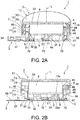
- FIG. 2 includes cross-sectional views of the linear actuator shown in FIG. 1 .
- the cross section of the linear actuator is seen from an obliquely upward direction; and in FIG. 2B , the cross section of the linear actuator is seen from a direction perpendicular to a moving direction of a movable element.
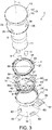
- FIG. 3 is an exploded perspective view of the linear actuator shown in FIG. 1 .
- a linear actuator 1 includes a movable element 2, a stationary element 3, and a spring (spring member) 4 that connects the movable element 2 and the stationary element 3.
- the stationary element 3 supports the movable element 2 in such a way as to be movable, by the intermediary of the spring 4. Between the movable element 2 and the stationary element 3, there are placed three damper members 5 being cylindrically shaped.
- the linear actuator 1 further includes a magnetic drive mechanism 7 in order to move the movable element 2.
- the magnetic drive mechanism 7 is provided with a permanent magnet 8 held by the movable element 2, and a drive coil 9 held by the stationary element 3.
- a moving direction of the movable element 2 is dealt with as a direction of an axis line 'L'.
- the direction of the axis line 'L' is consistent with a central axis line of the permanent magnet 8 mounted on the movable element 2 and a central axis line of the drive coil 9 mounted on the stationary element 3.
- an upside and a downside of the linear actuator 1 are explained as follows, with reference to upward and downward directions in the drawings. That is to say; in the direction of the axis line 'L', a side where the stationary element 3 is positioned is a downside, meanwhile a side where the movable element 2 is positioned is an upside.
- the movable element 2 is provided with the columnar permanent magnet 8 extending in the direction of the axis line 'L' (the moving direction of the movable element 2).
- the permanent magnet 8 is shaped so as to be flattened in such a way as to be short in the direction of the axis line 'L', and the permanent magnet 8 is magnetized with a north pole and a south pole in the direction of the axis line 'L'.
- the permanent magnet 8 is provided with a top end surface and a bottom end surface that are perpendicular to the direction of the axis line 'L'.
- the movable element 2 is provided with a core member 11 that overlaps with the permanent magnet 8 from a downside, and a yoke member 12 that covers up the permanent magnet 8 from an upside as well as an outer circumferential side.
- the permanent magnet 8, the core member 11 and the yoke member 12 are placed coaxially.
- the core member 11 and the yoke member 12 are made of a magnetic material.
- the core member 11 is a circular plate member having a constant thickness.
- a planar shape of the core member 11 is the same as a planar shape of the bottom end surface of the permanent magnet 8.
- the core member 11 is fixed to the bottom end surface of the permanent magnet 8 with an adhesive and the like.
- the core member 11 extends in a direction perpendicular to the axis line 'L'.
- the yoke member 12 includes an upper yoke member 13 and a lower yoke member 14.
- the upper yoke member 13 includes a circular end plate part 15 having a constant thickness, and an upper cylindrical part 16 protruding downward from an outer circumferential edge of the end plate part 15.
- the lower yoke member 14 includes a lower cylindrical part 17 that continues downward from a bottom end edge of the upper cylindrical part 16, and a protrusion plate part 18 protruding toward an inner circumferential side from a bottom end edge of the lower cylindrical part 17.
- the protrusion plate part 18 has a constant thickness, and its planar shape is annular. As shown in FIG.
- the bottom end edge of the upper cylindrical part 16 is provided with cutout parts 19 at three circumferential positions.
- Each of the cutout parts 19 is provided for purpose of sandwiching and holding a movable-element-side connection part 21 of the spring 4, between the upper cylindrical part 16 and the lower cylindrical part 17, at a time of connecting the upper cylindrical part 16 and the lower cylindrical part 17 by welding and the like.
- the yoke member 12 is provided with a magnetic plate 23 having a constant thickness, which is put into the upper yoke member 13 from a downside.
- the magnetic plate 23 is provided with a round center hole 24 at a center position, and three through-holes for welding 25, which are formed at outer circumferential fringe parts around the axis line 'L' at equal angular intervals.
- the magnetic plate 23 is fixed to the end plate part 15 of the upper yoke member 13, by way of welding that is carried out by making use of an open edge part of the three through-holes for welding 25.
- the magnetic plate 23 is laminated on the end plate part 15 in the direction of the axis line 'L'.
- the yoke member 12 is fixed to the permanent magnet 8, by way of bonding a bottom end surface of the magnetic plate 23 to the top end surface of the permanent magnet 8 with an adhesive and the like. Under a situation where the yoke member 12 is fixed to the permanent magnet 8, as shown in FIG. 2 , there is circumferentially formed a gap, having a constant clearance, between an annular outer-circumferential surface of the permanent magnet 8 and both the upper cylindrical part 16 as well as the lower cylindrical part 17.
- the protrusion plate part 18 is placed at a position that partially overlaps with the core member 11. Moreover, there is circumferentially formed a gap, having a constant clearance, between an annular inner-circumferential surface of the protrusion plate part 18 and an annular outer-circumferential surface of the core member 11.
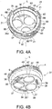
- FIG. 4A is a perspective view showing a situation where a coil bobbin is observed from an upper side; while the coil bobbin around which the drive coil 9 is wound, is provided with the spring 4; and meanwhile FIG. 4B is a perspective view showing a situation where the coil bobbin is observed from a lower side; while the coil bobbin around which the drive coil 9 is wound, is provided with the spring 4.
- the stationary element 3 is provided with a coil bobbin 31 (a first element) around which the drive coil 9 is wound, and a plate-like base 32 (a second element) that overlaps with the coil bobbin 31 from a side opposite to the movable element 2.
- the coil bobbin 31 supports the movable element 2 by the intermediary of the spring 4 in such a way as to be movable in the direction of the axis line 'L'.
- the coil bobbin 31 is made of a resin material. As shown in FIG. 2 , the coil bobbin 31 is provided with a bottom plate part 35 that faces the core member 11 of the movable element 2 in the direction of the axis line 'L', and a cylindrical part 36 that protrudes upward from the bottom plate part 35. An axis line 'L' of the cylindrical part 36 is consistent with an axis line 'L' of the permanent magnet 8.
- the slit 38 is positioned at a bottom of the locating concave part 39.
- the cylindrical part 36 is provided with three spring retainer projections 43 on its annular top end surface 36a, as shown in FIG. 4A .
- the three spring retainer projections 43 are placed around the axis line 'L' at equal angular intervals.
- Each of the spring retainer projections 43 works as a retainer part for retaining a stationary-element-side connection part 45 of the spring 4, and the cylindrical part 36 supports the stationary-element-side connection part 45 from a lower side.
- the cylindrical part 36 is provided with; a tubular torso part 46, wherein the drive coil 9 is wound around an outer circumferential surface of the tubular torso part 46; a lower flange part 47 being annular, which is expanded in its diameter at a lower side of the tubular torso part 46; and an upper flange part 48 being annular, which is expanded in its diameter at an upper side of the tubular torso part 46. Then, in a view from the direction of the axis line 'L', the upper flange part 48 has a larger diameter than the lower flange part 47 has.
- the lower flange part 47 protrudes a little out of an outer circumferential surface of the drive coil 9 toward an outer side in a radial direction, while the upper flange part 48 protrudes quite a little out of the outer circumferential surface of the drive coil 9 toward the outer side in the radial direction, in comparison with the lower flange part 47.
- each of the reinforcing ribs 49 has its outer circumferential surface that overlaps with an outer circumferential surface of the upper flange part 48. Moreover, as shown in FIG.
- each of the reinforcing ribs 49 is provided with; a rectangular leading surface 50 that leads to the annular top end surface 36a at an elevation being the same as the annular top end surface 36a; and a sloping surface 51 that slopes downward from the leading surface 50 toward one side in a circumferential direction.
- An end, at the one side in the circumferential direction, of the sloping surface 51 leads to a top surface of the upper flange part 48.
- the leading surface 50 of each of the reinforcing ribs 49 is displaced with respect to each of the spring retainer projections 43, in a circumferential direction, in such a way that there exists the sloping surface 51 at an outer circumferential side of each of the spring retainer projections 43.
- the base 32 is provided with a disk plate part 55 and a circuit board supporting part 57, being rectangular, which protrudes outward from the disk plate part 55 in a radial direction.
- a circuit board 59 is supported by the circuit board supporting part 57.
- a terminal of the drive coil 9 is connected to the circuit board 59.
- the disk plate part 55 is provided with a locating plate 63.
- the locating plate 63 is formed by way of cutting and raising a part of the disk plate part 55.
- the coil bobbin 31 is installed on the base 32, by way of inserting the locating plate 63 into the locating concave part 39 of the bottom surface 35a of the bottom plate part 35, so as to locate the coil bobbin 31 in a direction perpendicular to the direction of the axis line 'L' as well as a circumferential direction.
- the coil bobbin 31 is fixed to the base 32 by use of an adhesive.
- the bottom plate part 35 stays away from the base in the direction of the axis line 'L'; and between the bottom plate part 35 and the base, there exists an adhesive layer of an adhesive 70 having a certain thickness.
- the adhesive is, for example, of a ultraviolet curable type.
- the spring 4 is a flat spring component, whose thickness direction is oriented in the direction of the axis line 'L', As shown in FIG. 3 and FIG. 4A , the spring 4 is provided with; the movable-element-side connection part 21 connected to the movable element 2 (the yoke member 12); the stationary-element-side connection part 45, being annular, connected to the stationary element 3 (the coil bobbin 31); and a plurality of arm parts 65 connected to the movable-element-side connection part 21 and the stationary-element-side connection part 45.
- the stationary-element-side connection part 45 is placed at an inner circumferential side with respect to the movable-element-side connection part 21 and the arm parts 65; and meanwhile the movable-element-side connection part 21 is placed at an outer circumferential side with respect to the arm parts 65.
- the movable-element-side connection part 21 is divided into three parts in a circumferential direction.
- the arm parts 65 individually stretch in the circumferential direction from the three divided parts of the movable-element-side connection part 21.
- Each divided part of the movable-element-side connection part 21 is fixed to the movable element 2 by way of pinching between the upper yoke member 13 and the lower yoke member 14, while being inserted into each of the cutout parts 19 of the upper yoke member 13.
- retaining holes 66 into which the spring retainer projections 43 of the annular top end surface 36a of the coil bobbin 31 are individually fit.
- the spring 4 is connected to the coil bobbin 31 by way of inserting each of the spring retainer projections 43 into each of the retaining hole 66.
- tubular torso part 46 of the coil bobbin 31 and the drive coil 9 wound around the tubular torso part 46 are placed between an annular inner circumferential surface of the protrusion plate part 18 and an annular outer circumferential surface of the core member 11.
- annular outer circumferential surface of the upper flange part 48 of the coil bobbin 31 faces an inner circumferential surface of the lower cylindrical part 17 of the yoke member 12 across a narrow space thereof.
- the upper flange part 48 of the coil bobbin 31 and the lower cylindrical part 17 of the yoke member 12 make up a first stopper mechanism to restrict a movable range of the movable element 2 at a time when the movable element 2 moves due to an external force in a direction perpendicular to the axis line 'L'.
- the upper flange part 48 of the coil bobbin 31 and the protrusion plate part 18 of the yoke member 12 make up a second stopper mechanism to restrict a movable range of the movable element 2 at a time when the movable element 2 moves upward due to an external force.
- a length of each of the damper members 5 in the direction of the axis line 'L' is equal to a specified dimension 'S' to be described later, as shown in FIG. 2B .
- each of the damper members 5 is placed between the movable element 2 and the stationary element 3, while being inserted through each of the holes 37 for inserting the damper members, the holes 37 being provided in the bottom plate part 35 of the coil bobbin 31.
- a clearance is individually formed between the opening section edges of the holes 37 for inserting the damper members in the bottom plate part 35 and the damper members 5.
- each of the damper members 5 makes its top end surface contact with a bottom surface 11a (a movable-element-side facing surface) of the core member 11 of the movable element 2, and makes its bottom end surface contact with a top surface 32a (a stationary-element-side facing surface) of the base 32 of the stationary element 3.
- the damper members 5 of the present embodiment are made of silicone gel having a needle entering level of 90 to 110.
- the needle entering level shows a value of an entered depth of a 1/4-cone needle stressed for five seconds, with a total load of 9.38 grams at 25 degrees Celsius, as specified in JIS-K-2207 or JIS-K-2220; wherein the entered depth being expressed in 1/10 mm. The smaller the value is, the harder the material is.
- fixing the damper members 5 to the core member 11 as well as fixing the damper members 5 to the base 32 are carried out by making use of the adhesive 70, a gluing agent, or an adherence property of the silicone gel.
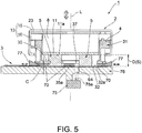
- FIG. 5 is an explanatory drawing of a method for manufacturing the linear actuator 1.
- the movable element 2 is supported by the coil bobbin 31 by the intermediary of the spring 4.
- the base 32 is held by a base holding jig 76 provided with a laser displacement meter 75 (distance measuring device).
- the adhesive 70 is applied to a plurality of spots on the bottom surface 35a of the bottom plate part 35 of the coil bobbin 31. Then, in a situation where the direction of the axis line 'L' of the coil bobbin 31 (i.e., the moving direction of the movable element 2) is orientated to a vertical direction, the coil bobbin 31 is placed onto the base 32.
- the locating plate 63 of the base 32 is inserted into the locating concave part 39 of the bottom surface 35a in the bottom plate part 35 of the coil bobbin 31, so that the coil bobbin 31 is located in a direction perpendicular to the direction of the axis line 'L' as well as in a circumferential direction, with respect to the base 32.
- the damper members 5 are inserted between the bottom surface 11a of the core member 11 of the movable element 2 and the top surface 32a of the base 32.
- a plurality of shims 77 are inserted between the base 32 and the coil bobbin 31 (the bottom plate part 35) so as to form a clearance 'C' between the base 32 and the coil bobbin 31.
- Each of the shims 77 is shaped to be like a wedge, in such a way that a thickness in a direction of the axis line 'L' gradually increases from an inner circumferential side toward an outer circumferential side.
- the shims 77 are individually placed around the axis line 'L' at equal angular intervals.
- the shims 77 are individually moved at the same time from an outer circumferential side toward an inner circumferential side.
- the coil bobbin 31 is shifted in the direction of the axis line 'L'.
- the laser displacement meter 75 measures a distance up to the movable element 2 (the core member 11).
- a distance dimension 'D' between the bottom surface 11a of the core member 11 and the top surface 32a of the base 32 is set with the specified dimension 'S' that is the same as the length of the damper members 5 in the direction of the axis line 'L'.
- the adhesive 70 is hardened to fix the coil bobbin 31 to the base 32.
- the bottom plate part 35 and the base are separated from each other in the direction of the axis line 'L', and there exists an adhesive layer of the adhesive 70, having a certain thickness, between the bottom plate part 35 and the base.
- the shims 77 are removed in a manufacturing step where the coil bobbin 31 and the base 32 are fixed to each other by use of the adhesive 70.
- a state shown in FIG. 2B is materialized so as to complete the linear actuator 1.
- the distance dimension 'D' between the bottom surface 11a of the core member 11 and the top surface 32a of the base 32 can be set with the specified dimension 'S' that is the same as the length of the damper members 5 in the direction of the axis line 'L'. Therefore, it is possible to avoid variations in a stroke and a resonance frequency of the movable element 2, among manufactured products, due to the damper members 5 inserted between the bottom surface 11a of the core member 11 and the top surface 32a of the base 32.
- the distance dimension 'D' from the bottom surface 11a of the core member 11 to the top surface 32a of the base 32 is a value as a result of a calculation, in which a thickness of the end plate part 15 of the yoke member 12, a thickness of the magnetic plate 23, a thickness of the permanent magnet 8, and a thickness of the first core member 11 are subtracted from a total dimension of summing a height of the coil bobbin 31, a thickness of the spring 4, and a height from the spring 4 to a top surface of the end plate part 15 of the yoke member 12; and therefore , the value as a result of a calculation includes accumulation of dimensional tolerances of the components described above.
- the dimension accuracies of the components must be improved so that manufacturing costs of the components increase.
- the laser displacement meter 75 measures the distance up to the movable element 2 (the core member 11) that is one of the members which the damper members 5 contact, and then a clearance dimension of the clearance 'C' between the coil bobbin 31 and the base 32 in the direction of the axis line 'L' is adjusted according to the distance, in such a way that the distance dimension 'D' from the bottom surface 11a of the core member 11 to the top surface 32a of the base 32 is set with the specified dimension 'S'.
- the dimension from the bottom surface 11a of the core member 11 of the movable element 2 to the top surface 32a of the base 32 can be set with the specified dimension 'S' corresponding to the length dimension of the damper members 5.
- a displacement meter of a mechanical type for measuring a distance by use of a measuring rod and the like may be used instead of such a displacement meter of an optical type.
- a measuring rod is made to contact the movable element 2 by way of the through-hole 64, in order to measure the distance.
- FIG. 6 is an explanatory drawing of another method for manufacturing the linear actuator 1.
- a positional relationship between the movable element 2, under conditions of being held by the movable-element-side holding jig 79, and the coil bobbin 31 is the same as a positional relationship between the movable element 2, under conditions where the coil bobbin 31 supports the movable element 2 while the direction of the axis line 'L' (the moving direction of the movable element 2) being consistent with a vertical direction, and the coil bobbin 31.
- the inspection light beam 75a is launched from the laser displacement meter 75 in a direction of the axis line 'L', in such a way as to be radiated onto the bottom surface 11a of the core member 11, by way of the through-hole 64 of the base 32 and one of the holes 37 for inserting the damper members of the coil bobbin 31.
- the laser displacement meter 75 measures a distance up to the bottom surface 11a of the core member 11.
- the laser displacement meter 75 measures a distance up to the movable element 2 (the core member 11). Then, based on the distance that is output from the laser displacement meter 75; a distance dimension 'D' between the bottom surface 11a of the core member 11 and the top surface 32a of the base 32 is set with the specified dimension 'S' that is the same as the length of the damper members 5 in the direction of the axis line 'L'.
- the adhesive 70 is hardened to fix the coil bobbin 31 to the base 32.
- the bottom plate part 35 and the base are separated from each other in the direction of the axis line 'L', and there exists an adhesive layer of the adhesive 70, having a certain thickness, between the bottom plate part 35 and the base.
- a state shown in FIG. 2B is materialized so as to complete the linear actuator 1.
- the distance dimension 'D' between the bottom surface 11a of the core member 11 and the top surface 32a of the base 32 can be set with the specified dimension 'S' that is the same as the length of the damper members 5 in the direction of the axis line 'L'. Therefore, it is possible to avoid variations in a stroke and a resonance frequency of the movable element 2, among manufactured products, due to the damper members 5 inserted between the bottom surface 11a of the core member 11 and the top surface 32a of the base 32.
Landscapes
- Engineering & Computer Science (AREA)
- Power Engineering (AREA)
- Manufacturing & Machinery (AREA)
- Reciprocating, Oscillating Or Vibrating Motors (AREA)
- Signal Processing (AREA)
Abstract
Description
- The present invention relates to a manufacturing method of a linear actuator and the linear actuator as well; the linear actuator being provided with a damper member between a movable element and a stationary element for suppressing resonance.
- As a device for notifying of an incoming call and the like of a mobile phone by way of a vibration, there is proposed a liner actuator. A linear actuator described in
Patent Document 1 is provided with a movable element having a permanent magnet, and a stationary element having a coil. The stationary element supports the movable element so as to be movable, by the intermediary of an elastic member, such as a spring component and the like. In the case of the linear actuator described in the document, an intensity level and a frequency of a vibration vary according to a driving signal supplied to the coil. - Patent Document 1: Japanese Patent Publication No.
2006-7161 - In a linear actuator, sometimes a movable element may resonate, depending on a vibration frequency, at a time when the movable element vibrates.
- In such a situation, it is conceivable for suppressing resonance to insert a damper member, which is extendable in a moving direction of the movable element, between a movable-element-side facing surface of the movable element and a stationary-element-side facing surface of a stationary element; the movable-element-side facing surface and the stationary-element-side facing surface facing each other in the moving direction of the movable element. Unfortunately, in this case, without controlling a dimension of a distance between the movable-element-side facing surface and the stationary-element-side facing surface where the damper member is inserted, in such a way as to make the dimension of the distance constant, a stroke and a resonance frequency of the movable element vary among manufactured products, due to the damper member inserted between the facing surfaces.
- With the issue described above being taken into consideration, it is an issue of the present invention to provide a manufacturing method of a linear actuator and the linear actuator as well; the linear actuator being able to avoid variations in a stroke and a resonance frequency of the movable element, among manufactured products, due to the damper member inserted between the movable element and the stationary element.
- In order to solve the issue described above, the present invention relates to a method for manufacturing a linear actuator having a movable element, a stationary element that supports the movable element by an intermediary of a spring member, and damper members inserted between a movable-element-side facing surface of the movable element and a stationary-element-side facing surface of the stationary element; the movable-element-side facing surface and the stationary-element-side facing surface facing each other in a moving direction of the movable element; the method includes: a provision of a first element and a second element to the stationary element; the second element having the stationary-element-side facing surface, and overlapping with the first element at a side opposite to the movable element in the moving direction; supporting the movable element with the first element by the intermediary of the spring member; setting a distance dimension between the movable-element-side facing surface and the stationary-element-side facing surface with a specified dimension corresponding to a length dimension of the damper members, by way of making a relative displacement between the first element and the second element in the moving direction, in a situation where a clearance is formed between the first element and the second element in the moving direction; and fixing the first element and the second element to each other by use of an adhesive, in the situation of having the clearance between the first element and the second element.
- In the present invention, by way of adjusting a clearance dimension of the clearance provided between the first element supporting the movable element and the second element having the stationary-element-side facing surface, the distance dimension between the movable-element-side facing surface and the stationary-element-side facing surface is set with the specified dimension. Then, the first element and the second element are fixed to each other by use of the adhesive, in the situation of having the clearance with the clearance dimension after the adjustment. According to the present invention, the distance dimension between the movable-element-side facing surface and the stationary-element-side facing surface can be set with a dimension corresponding to the length dimension of the damper members, and therefore, it is possible to avoid variations in a stroke and a resonance frequency of the movable element, among manufactured products, due to the damper members inserted between the movable-element-side facing surface and the stationary-element-side facing surface.
- In the present invention, it is preferable that the second element is provided with a through-hole passing through in the moving direction; after supporting the movable element by use of the first element, the second element is held by use of a jig equipped with a distance measuring device that is located at a side opposite to the movable element with respect to the second element; and a relative displacement is made between the first element and the jig in the moving direction so as to relatively move the first element and the second element; and meanwhile, the distance measuring device measures a distance up to the movable element by way of the through-hole in order to set the distance dimension with the specified dimension, based on the distance. According to this arrangement, the second element is provided with the through-hole so that it becomes easy to measure the distance up to the movable element by use of the distance measuring device. Therefore, the distance dimension between the movable-element-side facing surface and the stationary-element-side facing surface can accurately be set with the specified dimension.
- In the present invention, it is preferable that the distance up to the member provided with the movable-element-side facing surface in the movable element is measured. According to this arrangement, a dimension up to the member, which the damper members contact, is measured, and therefore the distance dimension between the movable-element-side facing surface and the stationary-element-side facing surface can further accurately be set with the specified dimension.
- In the present invention, it is preferable that the adhesive is applied to at least one of a first surface that overlaps with the second element in the first element, and a second surface that overlaps with the first element in the second element, before a relative displacement is made between the first element and the second element. According to this arrangement, it becomes easy to fix the first element and the second element to each other by use of the adhesive.
- In the present invention, a shim having a thickness in the moving direction, which gradually changes in a direction perpendicular to the moving direction, may be inserted between the first element and the second element in order to form the clearance between the first element and the second element; and a relative displacement may be made between the first element and the second element in the moving direction, by way of changing an amount of insertion of the shim between the first element and the second element. According to this arrangement, the clearance between the first element and the second element can accurately be adjusted by use of the shim.
- In this situation, the shim may be removed out of the clearance between the first element and the second element, after the adjustment; and in the meantime, the shim may as well be fixed between the first element and the second element by use of the adhesive.
- Then, in the present invention, a linear actuator includes; a movable element; a stationary element that supports the movable element by an intermediary of a spring member; and damper members inserted between a movable-element-side facing surface of the movable element and a stationary-element-side facing surface of the stationary element; the movable-element-side facing surface and the stationary-element-side facing surface facing each other in a moving direction of the movable element; wherein, the stationary element is provided with a first element supporting the movable element by the intermediary of the spring member, and a second element having the stationary-element-side facing surface, and overlapping with the first element at a side opposite to the movable element in the moving direction; a clearance is formed between the first element and the second element in order to adjust a distance dimension between the movable-element-side facing surface and the stationary-element-side facing surface; and the first element and the second element are fixed by use of an adhesive, in a situation of having the clearance between the first element and the second element.
- In the present invention, the clearance is provided between the first element supporting the movable element and the second element having the stationary-element-side facing surface in the stationary element; and therefore the distance dimension between the movable-element-side facing surface and the stationary-element-side facing surface can be set with a specified dimension corresponding to a length dimension of the damper members, by way of adjusting a clearance dimension of the clearance. Therefore, it is possible to avoid variations in a stroke and a resonance frequency of the movable element, among manufactured products, due to the damper members inserted between the movable-element-side facing surface and the stationary-element-side facing surface.
- In the present invention, it is preferable that the stationary element is provided with a through-hole for measuring a distance up to the movable element by use of a distance measuring device that is located at a side opposite to the movable element with respect to the stationary element. According to this arrangement, it becomes easy to measure the distance up to the movable element by use of the distance measuring device; and therefore the distance dimension between the movable-element-side facing surface and the stationary-element-side facing surface can accurately be set with the specified dimension.
- In the present invention, the linear actuator may include a shim having a thickness in the moving direction, which gradually changes in a direction perpendicular to the moving direction; and the shim may be inserted between the first element and the second element, and fixed by use of the adhesive. With such a shim provided, the clearance between the first element and the second element can accurately be adjusted by way of adjusting an amount of insertion of the shim between the first element and the second element.
- According to the present invention, the dimension of the distance between the movable-element-side facing surface of the movable element and the stationary-element-side facing surface of the stationary element, where the damper members are inserted, can be made to be the specified dimension. Therefore, it is possible to avoid a variance of the stroke and the resonance frequency of the movable element, due to the damper members inserted between the movable-element-side facing surface and the stationary-element-side facing surface.
-
-
FIG. 1 is a perspective view of a linear actuator according to a first embodiment of the present invention. -
FIG. 2 includes cross-sectional views of the linear actuator shown inFIG. 1 . -
FIG. 3 is an exploded perspective view of the linear actuator shown inFIG. 1 . -
FIG. 4 includes perspective views showing a coil bobbin, a driving coil, and a spring. -
FIG. 5 is an explanatory drawing of a method for manufacturing the linear actuator shown inFIG. 1 . -
FIG. 6 is an explanatory drawing of another method for manufacturing the linear actuator shown inFIG. 1 . - With reference to the drawings, a linear actuator according to an embodiment of the present invention is explained below.
-
FIG. 1 is a perspective view of a linear actuator according to a first embodiment of the present invention.FIG. 2 includes cross-sectional views of the linear actuator shown inFIG. 1 . InFIG. 2A , the cross section of the linear actuator is seen from an obliquely upward direction; and inFIG. 2B , the cross section of the linear actuator is seen from a direction perpendicular to a moving direction of a movable element.FIG. 3 is an exploded perspective view of the linear actuator shown inFIG. 1 . - As shown in
FIG. 1 through FIG. 3 , alinear actuator 1 includes amovable element 2, astationary element 3, and a spring (spring member) 4 that connects themovable element 2 and thestationary element 3. Thestationary element 3 supports themovable element 2 in such a way as to be movable, by the intermediary of thespring 4. Between themovable element 2 and thestationary element 3, there are placed threedamper members 5 being cylindrically shaped. Thelinear actuator 1 further includes amagnetic drive mechanism 7 in order to move themovable element 2. Themagnetic drive mechanism 7 is provided with apermanent magnet 8 held by themovable element 2, and adrive coil 9 held by thestationary element 3. In the following explanation, a moving direction of themovable element 2 is dealt with as a direction of an axis line 'L'. The direction of the axis line 'L' is consistent with a central axis line of thepermanent magnet 8 mounted on themovable element 2 and a central axis line of thedrive coil 9 mounted on thestationary element 3. For the purpose of convenience, an upside and a downside of thelinear actuator 1 are explained as follows, with reference to upward and downward directions in the drawings. That is to say; in the direction of the axis line 'L', a side where thestationary element 3 is positioned is a downside, meanwhile a side where themovable element 2 is positioned is an upside. - The
movable element 2 is provided with the columnarpermanent magnet 8 extending in the direction of the axis line 'L' (the moving direction of the movable element 2). Thepermanent magnet 8 is shaped so as to be flattened in such a way as to be short in the direction of the axis line 'L', and thepermanent magnet 8 is magnetized with a north pole and a south pole in the direction of the axis line 'L'. Thepermanent magnet 8 is provided with a top end surface and a bottom end surface that are perpendicular to the direction of the axis line 'L'. - In the meantime, the
movable element 2 is provided with acore member 11 that overlaps with thepermanent magnet 8 from a downside, and ayoke member 12 that covers up thepermanent magnet 8 from an upside as well as an outer circumferential side. Thepermanent magnet 8, thecore member 11 and theyoke member 12 are placed coaxially. Thecore member 11 and theyoke member 12 are made of a magnetic material. - As show in
FIG. 3 , thecore member 11 is a circular plate member having a constant thickness. A planar shape of thecore member 11 is the same as a planar shape of the bottom end surface of thepermanent magnet 8. Thecore member 11 is fixed to the bottom end surface of thepermanent magnet 8 with an adhesive and the like. Thecore member 11 extends in a direction perpendicular to the axis line 'L'. - The
yoke member 12 includes anupper yoke member 13 and alower yoke member 14. As shown inFIG. 2 , theupper yoke member 13 includes a circularend plate part 15 having a constant thickness, and an uppercylindrical part 16 protruding downward from an outer circumferential edge of theend plate part 15. Thelower yoke member 14 includes a lowercylindrical part 17 that continues downward from a bottom end edge of the uppercylindrical part 16, and aprotrusion plate part 18 protruding toward an inner circumferential side from a bottom end edge of the lowercylindrical part 17. Theprotrusion plate part 18 has a constant thickness, and its planar shape is annular. As shown inFIG. 1 , the bottom end edge of the uppercylindrical part 16 is provided withcutout parts 19 at three circumferential positions. Each of thecutout parts 19 is provided for purpose of sandwiching and holding a movable-element-side connection part 21 of thespring 4, between the uppercylindrical part 16 and the lowercylindrical part 17, at a time of connecting the uppercylindrical part 16 and the lowercylindrical part 17 by welding and the like. - Moreover, as shown in
FIG. 2 andFIG. 3 , theyoke member 12 is provided with amagnetic plate 23 having a constant thickness, which is put into theupper yoke member 13 from a downside. Themagnetic plate 23 is provided with around center hole 24 at a center position, and three through-holes for welding 25, which are formed at outer circumferential fringe parts around the axis line 'L' at equal angular intervals. Themagnetic plate 23 is fixed to theend plate part 15 of theupper yoke member 13, by way of welding that is carried out by making use of an open edge part of the three through-holes for welding 25. Thus, themagnetic plate 23 is laminated on theend plate part 15 in the direction of the axis line 'L'. - The
yoke member 12 is fixed to thepermanent magnet 8, by way of bonding a bottom end surface of themagnetic plate 23 to the top end surface of thepermanent magnet 8 with an adhesive and the like. Under a situation where theyoke member 12 is fixed to thepermanent magnet 8, as shown inFIG. 2 , there is circumferentially formed a gap, having a constant clearance, between an annular outer-circumferential surface of thepermanent magnet 8 and both the uppercylindrical part 16 as well as the lowercylindrical part 17. Meanwhile, at a time when a situation of theyoke member 12 being fixed to thepermanent magnet 8 is observed from a lateral direction perpendicular to the direction of the axis line 'L', theprotrusion plate part 18 is placed at a position that partially overlaps with thecore member 11. Moreover, there is circumferentially formed a gap, having a constant clearance, between an annular inner-circumferential surface of theprotrusion plate part 18 and an annular outer-circumferential surface of thecore member 11. - Next, the
stationary element 3 is explained with reference toFIG. 2 through FIG. 4 .FIG. 4A is a perspective view showing a situation where a coil bobbin is observed from an upper side; while the coil bobbin around which thedrive coil 9 is wound, is provided with thespring 4; and meanwhileFIG. 4B is a perspective view showing a situation where the coil bobbin is observed from a lower side; while the coil bobbin around which thedrive coil 9 is wound, is provided with thespring 4. As shown inFIG. 2 andFIG. 3 , thestationary element 3 is provided with a coil bobbin 31 (a first element) around which thedrive coil 9 is wound, and a plate-like base 32 (a second element) that overlaps with thecoil bobbin 31 from a side opposite to themovable element 2. Thecoil bobbin 31 supports themovable element 2 by the intermediary of thespring 4 in such a way as to be movable in the direction of the axis line 'L'. - The
coil bobbin 31 is made of a resin material. As shown inFIG. 2 , thecoil bobbin 31 is provided with abottom plate part 35 that faces thecore member 11 of themovable element 2 in the direction of the axis line 'L', and acylindrical part 36 that protrudes upward from thebottom plate part 35. An axis line 'L' of thecylindrical part 36 is consistent with an axis line 'L' of thepermanent magnet 8. - As shown in
FIG. 4A , threeholes 37 for inserting the damper members are formed in thebottom plate part 35. Theholes 37 for the damper members are individually provided around the axis line 'L' at equal angular intervals. Each of theholes 37 for inserting the damper members is an opening section having a larger diameter than thedamper members 5 have. Therefore, as shown inFIG. 2 ; under a situation where thedamper members 5 are individually positioned at inner circumferential sides of theholes 37 for inserting the damper members, a clearance is individually formed between thedamper members 5 and opening section edges of theholes 37 for inserting the damper members in thebottom plate part 35. Meanwhile, aslit 38, which linearly stretches in a circumferential direction, is formed between two of theholes 37 for inserting the damper members, which are neighboring in a circumferential direction. - As shown in
FIG. 4B , in abottom surface 35a of thebottom plate part 35, at a position corresponding to each slit 38, there is provided a locatingconcave part 39 stretching along theslit 38. Theslit 38 is positioned at a bottom of the locatingconcave part 39. - The
cylindrical part 36 is provided with threespring retainer projections 43 on its annulartop end surface 36a, as shown inFIG. 4A . The threespring retainer projections 43 are placed around the axis line 'L' at equal angular intervals. Each of thespring retainer projections 43 works as a retainer part for retaining a stationary-element-side connection part 45 of thespring 4, and thecylindrical part 36 supports the stationary-element-side connection part 45 from a lower side. - Moreover, as shown in
FIG. 2 , thecylindrical part 36 is provided with; atubular torso part 46, wherein thedrive coil 9 is wound around an outer circumferential surface of thetubular torso part 46; alower flange part 47 being annular, which is expanded in its diameter at a lower side of thetubular torso part 46; and anupper flange part 48 being annular, which is expanded in its diameter at an upper side of thetubular torso part 46. Then, in a view from the direction of the axis line 'L', theupper flange part 48 has a larger diameter than thelower flange part 47 has. Accordingly, in a situation where thedrive coil 9 is wound around thetubular torso part 46; thelower flange part 47 protrudes a little out of an outer circumferential surface of thedrive coil 9 toward an outer side in a radial direction, while theupper flange part 48 protrudes quite a little out of the outer circumferential surface of thedrive coil 9 toward the outer side in the radial direction, in comparison with thelower flange part 47. - Between the annular
top end surface 36a of an outer circumferential surface of thecylindrical part 36 and theupper flange part 48, there are provided three reinforcingribs 49 that reinforce theupper flange part 48. The three reinforcingribs 49 are provided around the axis line 'L' at equal angular intervals. In a view from the direction of the axis line 'L', each of the reinforcingribs 49 has its outer circumferential surface that overlaps with an outer circumferential surface of theupper flange part 48. Moreover, as shown inFIG. 3 , each of the reinforcingribs 49 is provided with; a rectangular leadingsurface 50 that leads to the annulartop end surface 36a at an elevation being the same as the annulartop end surface 36a; and asloping surface 51 that slopes downward from the leadingsurface 50 toward one side in a circumferential direction. An end, at the one side in the circumferential direction, of the slopingsurface 51 leads to a top surface of theupper flange part 48. The leadingsurface 50 of each of the reinforcingribs 49 is displaced with respect to each of thespring retainer projections 43, in a circumferential direction, in such a way that there exists the slopingsurface 51 at an outer circumferential side of each of thespring retainer projections 43. - As shown in
FIG. 3 , thebase 32 is provided with adisk plate part 55 and a circuitboard supporting part 57, being rectangular, which protrudes outward from thedisk plate part 55 in a radial direction. Acircuit board 59 is supported by the circuitboard supporting part 57. A terminal of thedrive coil 9 is connected to thecircuit board 59. - The
disk plate part 55 is provided with a locatingplate 63. The locatingplate 63 is formed by way of cutting and raising a part of thedisk plate part 55. Thecoil bobbin 31 is installed on thebase 32, by way of inserting the locatingplate 63 into the locatingconcave part 39 of thebottom surface 35a of thebottom plate part 35, so as to locate thecoil bobbin 31 in a direction perpendicular to the direction of the axis line 'L' as well as a circumferential direction. - Meanwhile, the
disk plate part 55 is provided with a through-hole 64 that passes through in the direction of the axis line 'L'. At a time of being viewed from the direction of the axis line 'L' in a situation where thecoil bobbin 31 is located and installed on thebase 32, the through-hole 64 is formed at a position that overlaps with an opening section of one of theholes 37 for inserting the damper members. In the meantime, as shown inFIG. 2A , the through-hole 64 is formed at the position that does not overlap with one of thedamper members 5 placed at an inner circumferential side of the one of theholes 37 for inserting the damper members. - The
coil bobbin 31 is fixed to thebase 32 by use of an adhesive. In a situation where thecoil bobbin 31 is fixed to thebase 32, thebottom plate part 35 stays away from the base in the direction of the axis line 'L'; and between thebottom plate part 35 and the base, there exists an adhesive layer of an adhesive 70 having a certain thickness. The adhesive is, for example, of a ultraviolet curable type. - The
spring 4 is a flat spring component, whose thickness direction is oriented in the direction of the axis line 'L', As shown inFIG. 3 andFIG. 4A , thespring 4 is provided with; the movable-element-side connection part 21 connected to the movable element 2 (the yoke member 12); the stationary-element-side connection part 45, being annular, connected to the stationary element 3 (the coil bobbin 31); and a plurality ofarm parts 65 connected to the movable-element-side connection part 21 and the stationary-element-side connection part 45. The stationary-element-side connection part 45 is placed at an inner circumferential side with respect to the movable-element-side connection part 21 and thearm parts 65; and meanwhile the movable-element-side connection part 21 is placed at an outer circumferential side with respect to thearm parts 65. - The movable-element-
side connection part 21 is divided into three parts in a circumferential direction. Thearm parts 65 individually stretch in the circumferential direction from the three divided parts of the movable-element-side connection part 21. Each divided part of the movable-element-side connection part 21 is fixed to themovable element 2 by way of pinching between theupper yoke member 13 and thelower yoke member 14, while being inserted into each of thecutout parts 19 of theupper yoke member 13. - In the stationary-element-
side connection part 45, there are formed retainingholes 66 into which thespring retainer projections 43 of the annulartop end surface 36a of thecoil bobbin 31 are individually fit. Thespring 4 is connected to thecoil bobbin 31 by way of inserting each of thespring retainer projections 43 into each of the retaininghole 66. - In a situation where the stationary-element-
side connection part 45 of thespring 4 is connected to thecoil bobbin 31, and meanwhile the movable-element-side connection part 21 is connected to theyoke member 12; thepermanent magnet 8 of themovable element 2 is positioned at an inner circumferential side of thecoil bobbin 31 of thestationary element 3, as shown inFIG. 2 . In the meantime, theprotrusion plate part 18 of theyoke member 12 is located between thelower flange part 47 and theupper flange part 48 of thecoil bobbin 31. Thus, thetubular torso part 46 of thecoil bobbin 31 and thedrive coil 9 wound around thetubular torso part 46 are placed between an annular inner circumferential surface of theprotrusion plate part 18 and an annular outer circumferential surface of thecore member 11. Moreover, an annular outer circumferential surface of theupper flange part 48 of thecoil bobbin 31 faces an inner circumferential surface of the lowercylindrical part 17 of theyoke member 12 across a narrow space thereof. - Under this situation, the
upper flange part 48 of thecoil bobbin 31 and the lowercylindrical part 17 of theyoke member 12 make up a first stopper mechanism to restrict a movable range of themovable element 2 at a time when themovable element 2 moves due to an external force in a direction perpendicular to the axis line 'L'. In the meantime, theupper flange part 48 of thecoil bobbin 31 and theprotrusion plate part 18 of theyoke member 12 make up a second stopper mechanism to restrict a movable range of themovable element 2 at a time when themovable element 2 moves upward due to an external force. - A length of each of the
damper members 5 in the direction of the axis line 'L' is equal to a specified dimension 'S' to be described later, as shown inFIG. 2B . As shown inFIG. 2A , each of thedamper members 5 is placed between themovable element 2 and thestationary element 3, while being inserted through each of theholes 37 for inserting the damper members, theholes 37 being provided in thebottom plate part 35 of thecoil bobbin 31. Incidentally, a clearance is individually formed between the opening section edges of theholes 37 for inserting the damper members in thebottom plate part 35 and thedamper members 5. As shown inFIG. 2B , each of thedamper members 5 makes its top end surface contact with abottom surface 11a (a movable-element-side facing surface) of thecore member 11 of themovable element 2, and makes its bottom end surface contact with atop surface 32a (a stationary-element-side facing surface) of thebase 32 of thestationary element 3. - Incidentally, the
damper members 5 of the present embodiment are made of silicone gel having a needle entering level of 90 to 110. The needle entering level shows a value of an entered depth of a 1/4-cone needle stressed for five seconds, with a total load of 9.38 grams at 25 degrees Celsius, as specified in JIS-K-2207 or JIS-K-2220; wherein the entered depth being expressed in 1/10 mm. The smaller the value is, the harder the material is. Incidentally, fixing thedamper members 5 to thecore member 11 as well as fixing thedamper members 5 to the base 32 are carried out by making use of the adhesive 70, a gluing agent, or an adherence property of the silicone gel. -
FIG. 5 is an explanatory drawing of a method for manufacturing thelinear actuator 1. At a time of manufacturing thelinear actuator 1, as shown inFIG. 5 , themovable element 2 is supported by thecoil bobbin 31 by the intermediary of thespring 4. In the meantime, thebase 32 is held by abase holding jig 76 provided with a laser displacement meter 75 (distance measuring device). - In a situation where the
base holding jig 76 holds thebase 32, thelaser displacement meter 75 is placed at a side opposite to themovable element 2 with respect to thebase 32. Meanwhile, thelaser displacement meter 75 is located at a position that enables aninspection light beam 75a (laser) from thelaser displacement meter 75 to be radiated to themovable element 2 by way of the through-hole 64 provided to thebase 32. In the present embodiment, theinspection light beam 75a is launched from thelaser displacement meter 75 in a direction of the axis line 'L', in such a way as to be radiated onto thebottom surface 11a of thecore member 11, by way of the through-hole 64 of thebase 32 and one of theholes 37 for inserting the damper members of thecoil bobbin 31. In such a way, thelaser displacement meter 75 measures a distance from thelaser displacement meter 75 to thebottom surface 11a of thecore member 11. - Next, the adhesive 70 is applied to a plurality of spots on the
bottom surface 35a of thebottom plate part 35 of thecoil bobbin 31. Then, in a situation where the direction of the axis line 'L' of the coil bobbin 31 (i.e., the moving direction of the movable element 2) is orientated to a vertical direction, thecoil bobbin 31 is placed onto thebase 32. At the time of placing thecoil bobbin 31 onto thebase 32, the locatingplate 63 of thebase 32 is inserted into the locatingconcave part 39 of thebottom surface 35a in thebottom plate part 35 of thecoil bobbin 31, so that thecoil bobbin 31 is located in a direction perpendicular to the direction of the axis line 'L' as well as in a circumferential direction, with respect to thebase 32. - Meanwhile, at the of time of placing the
coil bobbin 31 onto thebase 32, thedamper members 5 are inserted between thebottom surface 11a of thecore member 11 of themovable element 2 and thetop surface 32a of thebase 32. Moreover, at the of time of placing thecoil bobbin 31 onto thebase 32, a plurality ofshims 77 are inserted between the base 32 and the coil bobbin 31 (the bottom plate part 35) so as to form a clearance 'C' between the base 32 and thecoil bobbin 31. Each of theshims 77 is shaped to be like a wedge, in such a way that a thickness in a direction of the axis line 'L' gradually increases from an inner circumferential side toward an outer circumferential side. Theshims 77 are individually placed around the axis line 'L' at equal angular intervals. - Subsequently, the
shims 77 are individually moved at the same time from an outer circumferential side toward an inner circumferential side. Thus, by way of changing an amount of insertion of theshims 77 into a space between the base 32 and thecoil bobbin 31 in this way, thecoil bobbin 31 is shifted in the direction of the axis line 'L'. Meanwhile, in parallel with changing the amount of insertion of theshims 77, thelaser displacement meter 75 measures a distance up to the movable element 2 (the core member 11). Then, based on the distance that is output from thelaser displacement meter 75; a distance dimension 'D' between thebottom surface 11a of thecore member 11 and thetop surface 32a of thebase 32 is set with the specified dimension 'S' that is the same as the length of thedamper members 5 in the direction of the axis line 'L'. - Subsequently, the adhesive 70 is hardened to fix the
coil bobbin 31 to thebase 32. In a situation where thecoil bobbin 31 is fixed to thebase 32, thebottom plate part 35 and the base are separated from each other in the direction of the axis line 'L', and there exists an adhesive layer of the adhesive 70, having a certain thickness, between thebottom plate part 35 and the base. In the meantime, according to the present embodiment; theshims 77 are removed in a manufacturing step where thecoil bobbin 31 and the base 32 are fixed to each other by use of the adhesive 70. Thus, a state shown inFIG. 2B is materialized so as to complete thelinear actuator 1. - According to the present embodiment, the distance dimension 'D' between the
bottom surface 11a of thecore member 11 and thetop surface 32a of the base 32 can be set with the specified dimension 'S' that is the same as the length of thedamper members 5 in the direction of the axis line 'L'. Therefore, it is possible to avoid variations in a stroke and a resonance frequency of themovable element 2, among manufactured products, due to thedamper members 5 inserted between thebottom surface 11a of thecore member 11 and thetop surface 32a of thebase 32. - In other words, the distance dimension 'D' from the
bottom surface 11a of thecore member 11 to thetop surface 32a of thebase 32 is a value as a result of a calculation, in which a thickness of theend plate part 15 of theyoke member 12, a thickness of themagnetic plate 23, a thickness of thepermanent magnet 8, and a thickness of thefirst core member 11 are subtracted from a total dimension of summing a height of thecoil bobbin 31, a thickness of thespring 4, and a height from thespring 4 to a top surface of theend plate part 15 of theyoke member 12; and therefore , the value as a result of a calculation includes accumulation of dimensional tolerances of the components described above. Accordingly, it is not easy to obtain an accuracy of the distance dimension 'D' from thebottom surface 11a of thecore member 11 themovable element 2 to thetop surface 32a of thebase 32, based on dimension accuracies of the components described above. In the meantime, for obtaining the accuracy of the distance dimension 'D' from thebottom surface 11a of thecore member 11 of themovable element 2 to thetop surface 32a of thebase 32, based on the dimension accuracies of the components described above, the dimension accuracies of the components must be improved so that manufacturing costs of the components increase. - On the other hand, according to the present embodiment; the
laser displacement meter 75 measures the distance up to the movable element 2 (the core member 11) that is one of the members which thedamper members 5 contact, and then a clearance dimension of the clearance 'C' between thecoil bobbin 31 and the base 32 in the direction of the axis line 'L' is adjusted according to the distance, in such a way that the distance dimension 'D' from thebottom surface 11a of thecore member 11 to thetop surface 32a of thebase 32 is set with the specified dimension 'S'. Therefore, without any relation to the dimensional tolerances of the components, the dimension from thebottom surface 11a of thecore member 11 of themovable element 2 to thetop surface 32a of the base 32 can be set with the specified dimension 'S' corresponding to the length dimension of thedamper members 5. - Furthermore, according to the present embodiment; a distance between the
bottom surface 11a of thecore member 11 and thetop surface 32a of thebase 32 is set with the specified dimension 'S' that is the same as the length dimension of thedamper members 5, and therefore a stroke of themovable element 2 can be secured. - Incidentally, though the
shims 77 inserted between thecoil bobbin 31 and the base 32 in a manufacturing step of manufacturing thelinear actuator 1 are removed in the embodiment described above, theseshims 77 may remain fixed to thecoil bobbin 31 and the base 32 by use of the adhesive 70, without being removed. - Moreover, though the distance up to the
movable element 2 is measured by use of thelaser displacement meter 75 in the embodiment described above, a displacement meter of a mechanical type for measuring a distance by use of a measuring rod and the like may be used instead of such a displacement meter of an optical type. In such a case, a measuring rod is made to contact themovable element 2 by way of the through-hole 64, in order to measure the distance. - Next, another method for manufacturing the
linear actuator 1 without using theshims 77 is explained with reference toFIG. 6. FIG. 6 is an explanatory drawing of another method for manufacturing thelinear actuator 1. - At a time of manufacturing the
linear actuator 1 by way of the manufacturing method of the present embodiment; at first, themovable element 2 is supported by thecoil bobbin 31 by the intermediary of thespring 4. Then, thecoil bobbin 31 supporting themovable element 2 is held by a movable-element-side holding jig 79, in a situation where themovable element 2 does not move in the direction of the axis line 'L'. Furthermore, a situation is made in such a way that the adhesive 70 is applied to a plurality of spots on thebottom surface 35a of thebottom plate part 35 of thecoil bobbin 31. At this time, a positional relationship between themovable element 2, under conditions of being held by the movable-element-side holding jig 79, and thecoil bobbin 31 is the same as a positional relationship between themovable element 2, under conditions where thecoil bobbin 31 supports themovable element 2 while the direction of the axis line 'L' (the moving direction of the movable element 2) being consistent with a vertical direction, and thecoil bobbin 31. - In parallel with the conditions described above, the
base 32 is held by thebase holding jig 76 provided with the laser displacement meter 75 (distance measuring device). In a situation where thebase 32 is held by thebase holding jig 76, thelaser displacement meter 75 is placed at a side opposite to themovable element 2 with respect to thebase 32. Meanwhile, thelaser displacement meter 75 is located at a position that enables aninspection light beam 75a (laser) from thelaser displacement meter 75 to be radiated to themovable element 2 by way of the through-hole 64 provided to thebase 32. Theinspection light beam 75a is launched from thelaser displacement meter 75 in a direction of the axis line 'L', in such a way as to be radiated onto thebottom surface 11a of thecore member 11, by way of the through-hole 64 of thebase 32 and one of theholes 37 for inserting the damper members of thecoil bobbin 31. In such a way, thelaser displacement meter 75 measures a distance up to thebottom surface 11a of thecore member 11. - Then, in a situation where a clearance 'C' is formed between the
coil bobbin 31 and the base 32 in the direction of the axis line 'L'; a relative displacement in the direction of the axis line 'L' is made between the movable-element-side holding jig 79 and thebase holding jig 76 so as to relatively move thecoil bobbin 31 and the base 32 in the direction of the axis line 'L'. In the present embodiment, while thebase holding jig 76 is kept stationary, the movable-element-side holding jig 79 is moved in relation to thebase holding jig 76. Moreover, in parallel with the relative displacement between the movable-element-side holding jig 79 and thebase holding jig 76, thelaser displacement meter 75 measures a distance up to the movable element 2 (the core member 11). Then, based on the distance that is output from thelaser displacement meter 75; a distance dimension 'D' between thebottom surface 11a of thecore member 11 and thetop surface 32a of thebase 32 is set with the specified dimension 'S' that is the same as the length of thedamper members 5 in the direction of the axis line 'L'. - Subsequently, the adhesive 70 is hardened to fix the
coil bobbin 31 to thebase 32. In a situation where thecoil bobbin 31 is fixed to thebase 32, thebottom plate part 35 and the base are separated from each other in the direction of the axis line 'L', and there exists an adhesive layer of the adhesive 70, having a certain thickness, between thebottom plate part 35 and the base. Thus, a state shown inFIG. 2B is materialized so as to complete thelinear actuator 1. - According to the manufacturing method of the present embodiment as well, the distance dimension 'D' between the
bottom surface 11a of thecore member 11 and thetop surface 32a of the base 32 can be set with the specified dimension 'S' that is the same as the length of thedamper members 5 in the direction of the axis line 'L'. Therefore, it is possible to avoid variations in a stroke and a resonance frequency of themovable element 2, among manufactured products, due to thedamper members 5 inserted between thebottom surface 11a of thecore member 11 and thetop surface 32a of thebase 32. Furthermore, according to the present embodiment; a distance between thebottom surface 11a of thecore member 11 and thetop surface 32a of thebase 32 is set with the specified dimension 'S' that is the same as the length dimension of thedamper members 5, and therefore a stroke of themovable element 2 can be secured. - Incidentally, according to the manufacturing method of the present embodiment as well, a displacement meter of a mechanical type may be used instead of the displacement meter of the optical type.
-
- 1. linear actuator
- 2. movable element
- 3. stationary element
- 4. spring (spring member)
- 5. damper members
- 11. core member
- 11a. bottom surface of the core member (movable-element-side facing surface)
- 31. coil bobbin (first element)
- 32. base (second element)
- 32a. top surface of the base (stationary-element-side facing surface, i.e., second surface)
- 35a. bottom surface the bottom plate part (first surface)
- 64. through-hole
- 70. adhesive
- 75. laser displacement meter (distance measuring device)
- 76. base holding jig (jig)
- 77. shims
- 'C' clearance
- 'D' distant dimension
- 'L' axis line (moving direction)
- 'S' specified dimension
Claims (9)
- A method for manufacturing a linear actuator having a movable element, a stationary element that supports the movable element by an intermediary of a spring member, and damper members inserted between a movable-element-side facing surface of the movable element and a stationary-element-side facing surface of the stationary element; the movable-element-side facing surface and the stationary-element-side facing surface facing each other in a moving direction of the movable element; the method comprising:a provision of a first element and a second element to the stationary element; the second element having the stationary-element-side facing surface, and overlapping with the first element at a side opposite to the movable element in the moving direction;supporting the movable element with the first element by the intermediary of the spring member;setting a distance dimension between the movable-element-side facing surface and the stationary-element-side facing surface with a specified dimension corresponding to a length dimension of the damper members, by way of making a relative displacement between the first element and the second element in the moving direction, in a situation where a clearance is formed between the first element and the second element in the moving direction; andfixing the first element and the second element to each other by use of an adhesive, in the situation of having the clearance between the first element and the second element.
- The method for manufacturing a linear actuator according to claim 1;
wherein, the second element is provided with a through-hole passing through in the moving direction;
after supporting the movable element by use of the first element, the second element is held by use of a jig equipped with a distance measuring device that is located at a side opposite to the movable element with respect to the second element; and
a relative displacement is made between the first element and the jig in the moving direction so as to relatively move the first element and the second element; and meanwhile, the distance measuring device measures a distance up to the movable element by way of the through-hole in order to set the distance dimension with the specified dimension, based on the distance. - The method for manufacturing a linear actuator according to claim 2;
wherein, the distance measuring device measures a distance up to a member provided with the movable-element-side facing surface in the movable element. - The method for manufacturing a linear actuator according to any one of claim 1 through claim 3;
wherein, the adhesive is applied to at least one of a first surface that overlaps with the second element in the first element, and a second surface that overlaps with the first element in the second element, before a relative displacement is made between the first element and the second element. - The method for manufacturing a linear actuator according to any one of claim 1 through claim 4;
wherein, a shim having a thickness in the moving direction, which gradually changes in a direction perpendicular to the moving direction, is inserted between the first element and the second element in order to form the clearance between the first element and the second element; and
a relative displacement is made between the first element and the second element in the moving direction, by way of changing an amount of insertion of the shim between the first element and the second element. - The method for manufacturing a linear actuator according to claim 5;
wherein, the shim is fixed between the first element and the second element by use of the adhesive. - A linear actuator comprising:a movable element;a stationary element that supports the movable element by an intermediary of a spring member; anddamper members inserted between a movable-element-side facing surface of the movable element and a stationary-element-side facing surface of the stationary element; the movable-element-side facing surface and the stationary-element-side facing surface facing each other in a moving direction of the movable element;wherein, the stationary element is provided with a first element supporting the movable element by the intermediary of the spring member, and a second element having the stationary-element-side facing surface, and overlapping with the first element at a side opposite to the movable element in the moving direction;a clearance is formed between the first element and the second element in order to adjust a distance dimension between the movable-element-side facing surface and the stationary-element-side facing surface; andthe first element and the second element are fixed by use of an adhesive, in a situation of having the clearance between the first element and the second element.
- The linear actuator according to claim 7;
wherein, the stationary element is provided with a through-hole for measuring a distance up to the movable element by use of a distance measuring device that is located at a side opposite to the movable element with respect to the stationary element. - The linear actuator according to either of claim 7 or claim 8;
wherein, the linear actuator includes a shim having a thickness in the moving direction, which gradually changes in a direction perpendicular to the moving direction; and
the shim is inserted between the first element and the second element, and fixed by use of the adhesive.
Applications Claiming Priority (2)
| Application Number | Priority Date | Filing Date | Title |
|---|---|---|---|
| JP2015111644A JP6517591B2 (en) | 2015-06-01 | 2015-06-01 | Method of manufacturing linear actuator and linear actuator |
| PCT/JP2016/066095 WO2016194918A1 (en) | 2015-06-01 | 2016-06-01 | Method of manufacturing linear actuator, and linear actuator |
Publications (2)
| Publication Number | Publication Date |
|---|---|
| EP3306796A1 true EP3306796A1 (en) | 2018-04-11 |
| EP3306796A4 EP3306796A4 (en) | 2018-12-19 |
Family
ID=57441264
Family Applications (1)
| Application Number | Title | Priority Date | Filing Date |
|---|---|---|---|
| EP16803352.0A Withdrawn EP3306796A4 (en) | 2015-06-01 | 2016-06-01 | Method of manufacturing linear actuator, and linear actuator |
Country Status (6)
| Country | Link |
|---|---|
| US (1) | US20180083521A1 (en) |
| EP (1) | EP3306796A4 (en) |
| JP (1) | JP6517591B2 (en) |
| KR (1) | KR20180013855A (en) |
| CN (1) | CN107534374B (en) |
| WO (1) | WO2016194918A1 (en) |
Families Citing this family (5)
| Publication number | Priority date | Publication date | Assignee | Title |
|---|---|---|---|---|
| JP6715465B2 (en) * | 2017-04-19 | 2020-07-01 | パナソニックIpマネジメント株式会社 | Vibration type linear actuator, hair treatment machine and method of manufacturing vibration type linear actuator |
| JP7186010B2 (en) * | 2018-04-16 | 2022-12-08 | 日本電産サンキョー株式会社 | Actuator manufacturing method |
| JP7219103B2 (en) * | 2019-01-31 | 2023-02-07 | 日本電産サンキョー株式会社 | Manufacturing method of damper member |
| JP7339021B2 (en) * | 2019-05-30 | 2023-09-05 | ニデックインスツルメンツ株式会社 | actuator |
| US12627198B2 (en) * | 2023-03-06 | 2026-05-12 | Lanto Electronic Limited | Damper device and electronic apparatus |
Family Cites Families (11)
| Publication number | Priority date | Publication date | Assignee | Title |
|---|---|---|---|---|
| CA2258762C (en) * | 1996-06-21 | 2002-12-31 | Sanyo Electric Co., Ltd. | Notifying vibration generator and portable communications device wherein the generator is used |
| JP3560041B2 (en) * | 1996-09-11 | 2004-09-02 | Necトーキン株式会社 | Vibration actuator for voice and low frequency vibration generation |
| JPH11275846A (en) * | 1998-03-19 | 1999-10-08 | Tokin Corp | Vibration actuator |
| JPH11341780A (en) * | 1998-05-21 | 1999-12-10 | Tokin Corp | Vibration actuator |
| JP2003211087A (en) * | 2002-01-22 | 2003-07-29 | Nec Tokin Corp | Vibration actuator and display device |
| JP2006075734A (en) * | 2004-09-09 | 2006-03-23 | Namiki Precision Jewel Co Ltd | Flat vibration actuator |
| EP2355544A1 (en) * | 2009-12-21 | 2011-08-10 | Nxp B.V. | Suspension member for a vibration actuator |
| WO2013137578A1 (en) * | 2012-03-16 | 2013-09-19 | 크레신 주식회사 | Linear oscillator |
| JP6036143B2 (en) * | 2012-10-11 | 2016-11-30 | ミツミ電機株式会社 | Power generator |
| JP5889259B2 (en) * | 2013-02-18 | 2016-03-22 | 日本電産コパル株式会社 | Linear vibration actuator |
| CN204205904U (en) * | 2014-09-30 | 2015-03-11 | 浙江省东阳市诚基电机有限公司 | A kind of horizontal vibration motor |
-
2015
- 2015-06-01 JP JP2015111644A patent/JP6517591B2/en active Active
-
2016
- 2016-06-01 KR KR1020177029492A patent/KR20180013855A/en not_active Withdrawn
- 2016-06-01 US US15/562,756 patent/US20180083521A1/en not_active Abandoned
- 2016-06-01 WO PCT/JP2016/066095 patent/WO2016194918A1/en not_active Ceased
- 2016-06-01 EP EP16803352.0A patent/EP3306796A4/en not_active Withdrawn
- 2016-06-01 CN CN201680024944.XA patent/CN107534374B/en not_active Expired - Fee Related
Also Published As
| Publication number | Publication date |
|---|---|
| EP3306796A4 (en) | 2018-12-19 |
| JP2016226196A (en) | 2016-12-28 |
| US20180083521A1 (en) | 2018-03-22 |
| KR20180013855A (en) | 2018-02-07 |
| CN107534374B (en) | 2019-11-29 |
| WO2016194918A1 (en) | 2016-12-08 |
| JP6517591B2 (en) | 2019-05-22 |
| CN107534374A (en) | 2018-01-02 |
Similar Documents
| Publication | Publication Date | Title |
|---|---|---|
| EP3280037A1 (en) | Linear actuator and method for manufacturing linear actuator | |
| US20180083521A1 (en) | Manufacturing method of linear actuator, and linear actuator | |
| EP3176930A1 (en) | Linear actuator | |
| JP5564353B2 (en) | Lens drive device | |
| KR101504005B1 (en) | Lens module | |
| EP3121946A1 (en) | Linear actuator | |
| EP3477833B1 (en) | A linear actuator having an elastic injection-molded frame | |
| US11194226B2 (en) | Lens driving device, camera device, and electronic apparatus | |
| KR20110078488A (en) | Voice coil motor | |
| EP2154558A1 (en) | Optical scanning actuator | |
| KR102771690B1 (en) | Lens moving apparatus and camera module including the same | |
| CN101840049A (en) | Lens driver | |
| JP6307379B2 (en) | Linear actuator | |
| KR101807633B1 (en) | Vibration motor | |
| US12046974B2 (en) | Actuator | |
| US11506727B2 (en) | Magnetic field generating unit, position detecting device and method of manufacturing magnetic field generating unit | |
| KR101696927B1 (en) | Voice coil motor | |
| KR101068124B1 (en) | Voice Coil Motor for Camera Module | |
| JP2022103082A (en) | Lens driving device, camera device, and electronic apparatus | |
| CN103018008B (en) | The inspection method of inspection fixture and lens driving apparatus | |
| JP5637754B2 (en) | Lens holding device | |
| JP2012027044A (en) | Lens driving device and camera module incorporated with lens drive device | |
| KR20150087611A (en) | Camera module and method for auto focus thereof | |
| JP6307378B2 (en) | Linear actuator | |
| JP2019105492A (en) | Electrodynamic detector and method for manufacturing the same |
Legal Events
| Date | Code | Title | Description |
|---|---|---|---|
| STAA | Information on the status of an ep patent application or granted ep patent |
Free format text: STATUS: THE INTERNATIONAL PUBLICATION HAS BEEN MADE |
|
| PUAI | Public reference made under article 153(3) epc to a published international application that has entered the european phase |
Free format text: ORIGINAL CODE: 0009012 |
|
| STAA | Information on the status of an ep patent application or granted ep patent |
Free format text: STATUS: REQUEST FOR EXAMINATION WAS MADE |
|
| 17P | Request for examination filed |
Effective date: 20170928 |
|
| AK | Designated contracting states |
Kind code of ref document: A1 Designated state(s): AL AT BE BG CH CY CZ DE DK EE ES FI FR GB GR HR HU IE IS IT LI LT LU LV MC MK MT NL NO PL PT RO RS SE SI SK SM TR |
|
| AX | Request for extension of the european patent |
Extension state: BA ME |
|
| DAV | Request for validation of the european patent (deleted) | ||
| DAX | Request for extension of the european patent (deleted) | ||
| A4 | Supplementary search report drawn up and despatched |
Effective date: 20181120 |
|
| RIC1 | Information provided on ipc code assigned before grant |
Ipc: H02K 33/16 20060101ALI20181114BHEP Ipc: H02K 33/02 20060101AFI20181114BHEP Ipc: H02K 15/00 20060101ALI20181114BHEP |
|
| STAA | Information on the status of an ep patent application or granted ep patent |
Free format text: STATUS: EXAMINATION IS IN PROGRESS |
|
| 17Q | First examination report despatched |
Effective date: 20200121 |
|
| STAA | Information on the status of an ep patent application or granted ep patent |
Free format text: STATUS: THE APPLICATION HAS BEEN WITHDRAWN |
|
| 18W | Application withdrawn |
Effective date: 20200318 |