JP6715465B2 - Vibration type linear actuator, hair treatment machine and method of manufacturing vibration type linear actuator - Google Patents
Vibration type linear actuator, hair treatment machine and method of manufacturing vibration type linear actuator Download PDFInfo
- Publication number
- JP6715465B2 JP6715465B2 JP2017082964A JP2017082964A JP6715465B2 JP 6715465 B2 JP6715465 B2 JP 6715465B2 JP 2017082964 A JP2017082964 A JP 2017082964A JP 2017082964 A JP2017082964 A JP 2017082964A JP 6715465 B2 JP6715465 B2 JP 6715465B2
- Authority
- JP
- Japan
- Prior art keywords
- core
- linear actuator
- base
- claw portion
- permanent magnet
- Prior art date
- Legal status (The legal status is an assumption and is not a legal conclusion. Google has not performed a legal analysis and makes no representation as to the accuracy of the status listed.)
- Active
Links
Images


Classifications
-
- H—ELECTRICITY
- H02—GENERATION; CONVERSION OR DISTRIBUTION OF ELECTRIC POWER
- H02K—DYNAMO-ELECTRIC MACHINES
- H02K33/00—Motors with reciprocating, oscillating or vibrating magnet, armature or coil system
- H02K33/16—Motors with reciprocating, oscillating or vibrating magnet, armature or coil system with polarised armatures moving in alternate directions by reversal or energisation of a single coil system
-
- B—PERFORMING OPERATIONS; TRANSPORTING
- B26—HAND CUTTING TOOLS; CUTTING; SEVERING
- B26B—HAND-HELD CUTTING TOOLS NOT OTHERWISE PROVIDED FOR
- B26B19/00—Clippers or shavers operating with a plurality of cutting edges, e.g. hair clippers, dry shavers
- B26B19/28—Drive layout for hair clippers or dry shavers, e.g. providing for electromotive drive
- B26B19/282—Motors without a rotating central drive shaft, e.g. linear motors
-
- B—PERFORMING OPERATIONS; TRANSPORTING
- B26—HAND CUTTING TOOLS; CUTTING; SEVERING
- B26B—HAND-HELD CUTTING TOOLS NOT OTHERWISE PROVIDED FOR
- B26B19/00—Clippers or shavers operating with a plurality of cutting edges, e.g. hair clippers, dry shavers
- B26B19/28—Drive layout for hair clippers or dry shavers, e.g. providing for electromotive drive
- B26B19/288—Balance by opposing oscillation
-
- H—ELECTRICITY
- H02—GENERATION; CONVERSION OR DISTRIBUTION OF ELECTRIC POWER
- H02K—DYNAMO-ELECTRIC MACHINES
- H02K33/00—Motors with reciprocating, oscillating or vibrating magnet, armature or coil system
- H02K33/02—Motors with reciprocating, oscillating or vibrating magnet, armature or coil system with armatures moved one way by energisation of a single coil system and returned by mechanical force, e.g. by springs
- H02K33/04—Motors with reciprocating, oscillating or vibrating magnet, armature or coil system with armatures moved one way by energisation of a single coil system and returned by mechanical force, e.g. by springs wherein the frequency of operation is determined by the frequency of uninterrupted AC energisation
- H02K33/06—Motors with reciprocating, oscillating or vibrating magnet, armature or coil system with armatures moved one way by energisation of a single coil system and returned by mechanical force, e.g. by springs wherein the frequency of operation is determined by the frequency of uninterrupted AC energisation with polarised armatures
-
- H—ELECTRICITY
- H02—GENERATION; CONVERSION OR DISTRIBUTION OF ELECTRIC POWER
- H02K—DYNAMO-ELECTRIC MACHINES
- H02K7/00—Arrangements for handling mechanical energy structurally associated with dynamo-electric machines, e.g. structural association with mechanical driving motors or auxiliary dynamo-electric machines
- H02K7/04—Balancing means
-
- H—ELECTRICITY
- H02—GENERATION; CONVERSION OR DISTRIBUTION OF ELECTRIC POWER
- H02K—DYNAMO-ELECTRIC MACHINES
- H02K7/00—Arrangements for handling mechanical energy structurally associated with dynamo-electric machines, e.g. structural association with mechanical driving motors or auxiliary dynamo-electric machines
- H02K7/10—Structural association with clutches, brakes, gears, pulleys or mechanical starters
- H02K7/104—Structural association with clutches, brakes, gears, pulleys or mechanical starters with eddy-current brakes
Description
本発明は、振動型リニアアクチュエータ、体毛処理機及び振動型リニアアクチュエータの製造方法に関する。 The present invention relates to a vibration type linear actuator, a hair treatment machine, and a method of manufacturing a vibration type linear actuator.
従来、電動バリカン及び電動シェーバーなどには、可動刃を振動させるための振動型リニアアクチュエータが備えられている。振動型リニアアクチュエータには、コア、コイルボビン及び巻線を備えた電磁石である固定子と、固定子に対して可動する可動子とが設けられている。ここで、コアには外方に突出した複数の突部が形成されており、この突部を、可動子と一体化された支持部に嵌め込むことで、可動子が保持している永久磁石とコアとを位置決めしている。 Conventionally, an electric hair clipper, an electric shaver, and the like are equipped with a vibration-type linear actuator for vibrating a movable blade. The vibration linear actuator is provided with a stator that is an electromagnet including a core, a coil bobbin, and a winding, and a mover that is movable with respect to the stator. Here, the core is formed with a plurality of outwardly projecting protrusions, and by fitting the protrusions into a support portion integrated with the mover, the permanent magnet held by the mover is retained. And the core are positioned.
ところで、各部品の個体差によって寸法にばらつきが生じているのが実状であり、単にコアの突部を支持部に嵌め込んだとしても、永久磁石とコアとの位置決めにもばらつきが発生してしまう。永久磁石とコアとの位置関係がばらつくと、振動型リニアアクチュエータの個体ごとの性能ばらつきの原因となる。 By the way, the actual situation is that there are variations in dimensions due to individual differences in each component, and even if the protrusions of the core are simply fitted into the support portions, variations occur in the positioning of the permanent magnets and the core. I will end up. Variations in the positional relationship between the permanent magnets and the core cause variations in the performance of the vibration-type linear actuators.
そこで、本発明は、部品に個体差があったとしても、永久磁石とコアとの位置決めの正確性を高めて、振動型リニアアクチュエータの個体ごとの性能ばらつきを抑制することを目的とする。 Therefore, an object of the present invention is to improve the accuracy of positioning the permanent magnet and the core even if there are individual differences in the parts, and suppress the performance variation among the individual vibration linear actuators.
上記目的を達成するため、本発明の一態様に係る振動型リニアアクチュエータは、電磁石を有する電磁コアブロックと、電磁石に対して所定の間隔をあけて対向するように永久磁石を保持する磁性ブロックとを備え、電磁コアブロックは、電磁石をなすコア及びコイルボビンと、コア及びコイルボビンを保持する基台とを一体的に備え、磁性ブロックは、永久磁石と、永久磁石を揺動自在に保持するとともに、電磁コアブロックを保持するフレームとを備え、フレームには、永久磁石と電磁石との位置関係が調整されるように電磁コアブロックを案内するためのガイド部が形成されており、ガイド部内で基台がフレームに固定されている。 In order to achieve the above object, a vibrating linear actuator according to an aspect of the present invention includes an electromagnetic core block having an electromagnet, and a magnetic block holding a permanent magnet so as to face the electromagnet at a predetermined interval. The electromagnetic core block integrally includes a core and a coil bobbin that form an electromagnet, and a base that holds the core and the coil bobbin, and the magnetic block holds the permanent magnet and the permanent magnet swingably. A frame for holding the electromagnetic core block is provided, and a guide portion for guiding the electromagnetic core block is formed in the frame so that the positional relationship between the permanent magnet and the electromagnet is adjusted. Is fixed to the frame.
また、本発明の一態様に係る体毛処理機は、上記振動型リニアアクチュエータと、振動型リニアアクチュエータに接続された可動刃とを備える。 A hair treatment machine according to one aspect of the present invention includes the above-described vibration-type linear actuator and a movable blade connected to the vibration-type linear actuator.
また、本発明の一態様に係る振動型アクチュエータの製造方法は、上記振動型リニアアクチュエータの製造方法であって、コア及びコイルボビンを基台に組み付けることで電磁コアブロックを組み立ててから、当該電磁コアブロックをフレームのガイド部によって案内させることで、永久磁石と電磁石との位置関係を調整した後に、基台をガイド部内でフレームに固定する。 A method of manufacturing a vibration-type actuator according to an aspect of the present invention is the method of manufacturing a vibration-type linear actuator, wherein the core and the coil bobbin are assembled to a base to assemble an electromagnetic core block, and then the electromagnetic core is assembled. By guiding the block by the guide portion of the frame, the positional relationship between the permanent magnet and the electromagnet is adjusted, and then the base is fixed to the frame within the guide portion.
本発明によれば、部品に個体差があったとしても、永久磁石とコアとの位置決めの正確性を高めることができ、振動型リニアアクチュエータの個体ごとの性能ばらつきを抑制することができる。 According to the present invention, even if there are individual differences in parts, it is possible to improve the accuracy of positioning the permanent magnet and the core, and it is possible to suppress performance variations among individual vibration type linear actuators.
以下では、本発明の実施の形態に係る体毛処理機及び振動型リニアアクチュエータについて、図面を用いて詳細に説明する。なお、以下に説明する実施の形態は、いずれも本発明の好ましい一具体例を示すものである。したがって、以下の実施の形態で示される数値、形状、材料、構成要素、構成要素の配置及び接続形態などは、一例であり、本発明を限定する趣旨ではない。よって、以下の実施の形態における構成要素のうち、本発明の最上位概念を示す独立請求項に記載されていない構成要素については、任意の構成要素として説明される。 Hereinafter, a hair treatment machine and a vibration type linear actuator according to an embodiment of the present invention will be described in detail with reference to the drawings. It should be noted that each of the embodiments described below shows a preferred specific example of the present invention. Therefore, the numerical values, shapes, materials, constituent elements, arrangement of constituent elements, connection forms, and the like shown in the following embodiments are examples, and are not intended to limit the present invention. Therefore, among the constituent elements in the following embodiments, the constituent elements that are not described in the independent claims showing the highest concept of the present invention are described as arbitrary constituent elements.
また、各図は、模式図であり、必ずしも厳密に図示されたものではない。また、各図において、同じ構成部材については同じ符号を付している。 In addition, each drawing is a schematic diagram and is not necessarily strictly illustrated. Further, in each drawing, the same reference numerals are given to the same constituent members.
[体毛処理機]
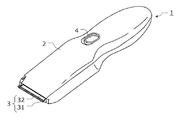
まず、実施の形態に係る体毛処理機について説明する。図1は、実施の形態に係る体毛処理機1の概略構成を示す斜視図である。体毛処理機1は、例えば電動バリカンであり、ケース2と、ブレードユニット3と、スイッチ4とを備えている。ケース2には、ブレードユニット3を駆動するための振動型リニアアクチュエータ100(図2等参照)が収容されている。
[Body treatment machine]
First, the hair treatment machine according to the embodiment will be described. FIG. 1 is a perspective view showing a schematic configuration of a hair treatment machine 1 according to an embodiment. The hair treatment machine 1 is, for example, an electric hair clipper, and includes a
ブレードユニット3は、ケース2の先端部分に取り付けられている。ブレードユニット3は、髪をカットする役割を持つ。具体的には、ブレードユニット3は、固定刃31及び可動刃32を含む。固定刃31は、ケース2の先端部分に固定されている。可動刃32は、振動型リニアアクチュエータ100の出力軸500(図2等参照)に接続されている。また、固定刃31及び可動刃32は、対向する面で相互に接触している。可動刃32は、振動型リニアアクチュエータ100により、固定刃31に対して往復運動する。この往復運動によってブレードユニット3が髪をカットする。
The
[振動型リニアアクチュエータ]
次に、振動型リニアアクチュエータ100について詳細に説明する。
[Vibration type linear actuator]
Next, the vibration
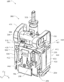
図2は、実施の形態に係る振動型リニアアクチュエータの概略構成を示す斜視図である。図3は、実施の形態に係る振動型リニアアクチュエータの概略構成を示す正面図である。図4は、実施の形態に係る振動型リニアアクチュエータの概略構成を示す側面図である。図5は、実施の形態に係る振動型リニアアクチュエータの概略構成を示す背面図である。図6は、実施の形態に係る振動型リニアアクチュエータの概略構成を示す分解斜視図である。 FIG. 2 is a perspective view showing a schematic configuration of the vibration type linear actuator according to the embodiment. FIG. 3 is a front view showing a schematic configuration of the vibration type linear actuator according to the embodiment. FIG. 4 is a side view showing a schematic configuration of the vibration type linear actuator according to the embodiment. FIG. 5 is a rear view showing a schematic configuration of the vibration linear actuator according to the embodiment. FIG. 6 is an exploded perspective view showing a schematic configuration of the vibration type linear actuator according to the embodiment.
なお、図2〜図6では、X軸方向を可動刃32の振動方向とし、Y軸方向を可動刃32と固定刃31との並び方向とし、Z軸方向を出力軸500の軸方向とした三次元の直交座標系で各部を図示している。なお、使用態様によってはZ軸方向が上下方向にならない場合も考えられるが、以下では説明の便宜のため、Z軸方向を上下方向として説明する。
2 to 6, the X-axis direction is the vibration direction of the
図2〜図6に示す振動型リニアアクチュエータ100は、電磁コアブロック200と、磁性ブロック300とを備えている。
The vibration
[電磁コアブロック]
電磁コアブロック200は、電磁石をなす電磁部210と、電磁部210を保持する基台250とを備えている。
[Electromagnetic core block]
The
電磁部210は、コイルボビン220と、コイル230と、コア240とを備えている。
The
図6に示すように、コイルボビン220は、絶縁体によって角筒状に形成されている。このコイルボビン220には、導電性のコイル230が巻き付けられている。コイルボビン220の下端部には、コア240と基台250との相対的な移動を規制する規制突起221が形成されている。具体的には、規制突起221は、コイルボビン220の下端部における一縁辺に形成されている。規制時における規制突起221と、各部との位置関係については、後述する。
As shown in FIG. 6, the
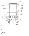
図7は、実施の形態に係るコア240と基台250との組立前の状態を示す分解斜視図である。図8は、実施の形態に係るコア240と基台250との組み立て後の状態を示す部分断面図である。なお、図8においては、電磁部210におけるコイルボビン220とコイル230との外形を二点鎖線で示している。
FIG. 7 is an exploded perspective view showing a state before assembling
図7及び図8に示すように、コア240は、基部241と、三本の柱部242、243、244と、二本の脚部245、246とを備えており、これらが磁性体によって一体的に形成されている。
As shown in FIGS. 7 and 8, the
基部241は、平板状に形成されており、この基部241の上面には、三本の柱部242、243、244が所定の間隔をあけて設けられている。他方、基部241の下面には、二本の脚部245、246が所定の間隔をあけて設けられている。三本の柱部242、243、244のうち、両端の柱部242、244は、二本の脚部245、246に対して上下方向(Z軸方向)で対向している。また、中央の柱部243には、コイルボビン220が取り付けられる。この状態で、コイル230に交流電流が供給されると、コア240の各柱部242、243、244には磁力が発生する。ここで、コイル230には交流電流が供給されているので、各柱部242、243、244の先端面242a、243a、244aでは、N極とS極とが周期的に入れ替わることになる。
The
また、二本の脚部245、246のそれぞれの外側面には、Z軸方向に交差するように外方に向けて突出した複数の第一爪部247が形成されている。具体的には、複数の第一爪部247は、Y軸方向に所定の間隔をあけて配置されて、X軸方向に沿って突出している。
Further, a plurality of
基台250は、例えば絶縁体から形成されており、コア240を支持する台座260と、台座260から立設する四本のガイド柱270とを一体的に備えている。
The
台座260には、コア240の二本の脚部245、246を係止する係止部261が形成されている。具体的には、係止部261は、二本の脚部245、246が挿通される挿通部262と、コア240の基部241を下方から支持する支持部263とを備えている。挿通部262内においては、二本の脚部245、246の各第一爪部247のZ軸方向の経路となる複数のスリット264が形成されている。複数のスリット264は、Z軸方向に貫通している。複数のスリット264の間の部分は、第二爪部265である。複数の第二爪部265は、Z軸方向に交差するように内方に向けて突出している。具体的には、複数の第二爪部265は、Y軸方向に所定の間隔をあけて配置されて、X軸方向に沿って突出している。
The
図8に示すように、複数の第二爪部265の下方には、各第一爪部247の水平方向の経路となる空間266が形成されている。組立時に複数の第一爪部247が空間266内を水平方向に移動する際には、コア240の基部241も支持部263の上面に沿って移動する。この移動によって、複数の第一爪部247と複数の第二爪部265とが対向することで、第二爪部265が第一爪部247に係合した状態となる。この第一爪部247が第二爪部265に係合する位置を係合位置とする。係合位置まで第一爪部247を案内する係合経路は、スリット264と空間266とによって形成されている。つまり、基台250には、係合経路が形成されている。
As shown in FIG. 8, a
第二爪部265が第一爪部247に係合した状態では、コア240が第二爪部265と支持部263とによってロックされるため、コア240の上下方向への移動が規制されている。この状態で、コイルボビン220がコア240に組み付けられると、コア240と基台250との間に規制突起221が嵌合する。具体的には、規制突起221は、コア240の基部241と、基台250の台座260との、Y軸方向における間に嵌合する。これにより、規制突起221は、第一爪部247が係合位置から移動しないようにコア240の移動を規制している。
In the state where the
四本のガイド柱270は、上面視で仮想的な矩形の各角部に対応する位置に配置されている。四本のガイド柱270は、Z軸方向に沿うように台座260から立設している。四本のガイド柱270は、後述する磁性ブロック300に備わるフレーム400によって案内される部位である。
The four
[磁性ブロック]
図2〜図6に示すように、磁性ブロック300は、フレーム400と、出力軸500と、一対の永久磁石301、302と、一対のバックヨーク303、304と、一対の錘305、306と、接続部309とを備えている。
[Magnetic block]
As shown in FIGS. 2 to 6, the
フレーム400は、出力軸500と、一対の永久磁石301、302と、一対のバックヨーク303、304と、一対の錘305、306と、接続部309とを保持するとともに、電磁コアブロック200を保持する。具体的には、フレーム400は、例えば樹脂により一体成形されており、互いに異なる位相で揺動する第一保持部410及び第二保持部420と、第一保持部410及び第二保持部420を連結する一対の連結バネ431、432と、電磁コアブロック200を保持する第三保持部440とを備えている。
The
第一保持部410は、一組の永久磁石301、バックヨーク303及び錘305と、出力軸500とを保持している。具体的には、第一保持部410は、X軸方向に延在する長尺板状の第一固定部411と、第一固定部411の両端部から垂れ下がり、第三保持部440に連結された一対の第一バネ部412、413とを備えている。
The
第一固定部411には、下方から永久磁石301、バックヨーク303、出力軸500という順でこれらが載置されて、ネジ止めされている。具体的には、第一固定部411には、長板状の永久磁石301を第一固定部411とで挟んで固定するように、バックヨーク303がネジ止めされている。この第一固定部411を介して、永久磁石301と電磁部210とが上下方向に所定の間隔をあけて対向している。
On the
出力軸500は、本体部510と、軸部520と、錘支持部530とを備えている。
The
本体部510は、第一固定部411に連結される部位であり、クランク状に形成されている。本体部510の中央部には、開口部511が形成されている。
The
軸部520は、本体部510の上側の一端部から上方に向けて突出した略円柱状の部位である。この軸部520には、可動刃32が接続されているので、第一保持部410の揺動に連動して可動刃32も連動することになる。
The
錘支持部530は、本体部510の他端部から下方に向けて垂れ下がった部位である。この錘支持部530は、錘305を支持している。
The
第二保持部420は、他の組の永久磁石302、バックヨーク304及び錘306を保持している。また、錘306は、接続部309を介してバックヨーク304に接続されている。
The
第二保持部420は、X軸方向に延在する長尺板状の第二固定部421と、第二固定部421の両端部から垂れ下がり、第三保持部440に連結された一対の第二バネ部422、423とを備えている。第二保持部420は、第一保持部410に対してY軸方向で隣り合っている。
The
第二固定部421には、下方から永久磁石302、バックヨーク304、接続部309及び錘306という順でこれらが載置されて、ネジ止めされている。具体的には、第二固定部421には、長板状の永久磁石302を第二固定部421とで挟んで固定するように、バックヨーク304がネジ止めされている。この第二固定部421を介して、永久磁石302と電磁部210とが上下方向に所定の間隔をあけて対向している。なお、永久磁石301と永久磁石302とは、互いの極性が反転するように配置されている。例えば、X軸方向において、永久磁石301の負側端部がN極、正側端部がS極の場合、永久磁石302の負側端部がS極、正側端部がN極となるように、永久磁石301、302を配置する。
On the
また、接続部309はバックヨーク304に対してネジ止めされている。また、接続部309は、出力軸500の開口部511を通過するように延在しており、その先端部に錘306がネジ止めされている。これにより、錘306は、第一保持部410の第一固定部411に対向した位置に配置されている。
The connecting
一対の連結バネ431、432は、偏平に湾曲した板バネであり、第一保持部410と第二保持部420とを揺動自在に連結している。具体的には、一対の連結バネ431、432のうち、一方の連結バネ431は、第一保持部410の第一固定部411の一端部と、第二保持部420の第二固定部421の一端部とを連結している。また、他方の連結バネ432は、第一保持部410の第一固定部411の他端部と、第二保持部420の第二固定部421の他端部とを連結している。
The pair of connection springs 431 and 432 are flat springs that are flatly curved, and swingably connect the
第三保持部440は、上面視矩形状の開口441を有する枠体である。この第三保持部440における開口441をなす部分が、電磁コアブロック200を案内するためのガイド部450である。具体的には、ガイド部450は、開口441をなす内壁面であり、Z軸方向に沿って連続して形成されている。矩形状の開口441の各角部には、基台250の各ガイド柱270が対応する。つまり、開口441の各角部において、各ガイド柱270は、ガイド部450である内壁面に沿ってZ軸方向に案内されることになる。Z軸方向は案内方向に相当する。そして、組立時においては、ガイド部450に沿って電磁コアブロック200の基台250が案内されることで、永久磁石301、302と、電磁部210(電磁石)とのZ軸方向での位置関係を調整することが可能である。そして、このガイド部450内において、基台250がフレーム400に固定されている。
The
第三保持部440には、第一保持部410の第一バネ部412、413と、第二保持部420の第二バネ部422、423とが連結されている。このため、第一バネ部412、413及び第二バネ部422、423は、第三保持部440との連結箇所を起点にして揺れ動く。
To the
[動作]
次に、振動型リニアアクチュエータ100の動作について説明する。
[motion]
Next, the operation of the vibration type
電磁石をなす電磁部210のコイル230に交流電流が供給されると、コア240の各柱部242、243、244の先端面242a、243a、244aでは、N極とS極とが周期的に入れ替わる。
When an alternating current is supplied to the
一方、第一保持部410で保持された永久磁石301と、第二保持部420で保持された永久磁石302とは、互いの極性が反転するように配置されている。このため、電磁部210と永久磁石301、302との電磁力によって、永久磁石301と永久磁石302とには、X軸方向に沿った互いに逆方向の移動力が周期的に作用する。これによって、第一保持部410と第二保持部420とが逆位相で揺動する。そして、第一保持部410に保持されている出力軸500も同様に揺動するために、可動刃32もX軸方向に往復運動することになる。
On the other hand, the
[製造方法]
次に、振動型リニアアクチュエータ100の製造方法について説明する。
[Production method]
Next, a method for manufacturing the vibration
まず、電磁コアブロック200の組み立て手順について説明する。図9は、実施の形態に係る電磁コアブロック200の組立方法の一工程を示す斜視図である。また、図10は、図9と同工程での実施の形態に係る電磁コアブロック200の状態を示す部分断面図である。なお、ここでは、作業者が組み立てを行う場合を例示するが、組立装置が組み立てを行ってもよい。
First, the procedure for assembling the
まず、作業者は、基台250に対してコア240を組み付ける。具体的には、作業者は、図7に示す状態から、コア240の各第一爪部247が、基台250のスリット264を通過するように、コア240の脚部245、246を、基台250の挿通部262に挿通する。これにより、基台250とコア240とが図9及び図10に示す状態となる。
First, the worker attaches the core 240 to the
次いで、作業者は、コア240をY軸方向にスライドさせると、各第一爪部247が空間266内を移動して係合位置に到達する(図8参照)。係合位置では、第二爪部265が第一爪部247に係合することにより、コア240が第二爪部265と支持部263とによってロックされるため、コア240の上下方向への移動が規制される。
Next, when the worker slides the
その後、作業者は、コイル230が巻き付けられたコイルボビン220を、コア240の柱部243に取り付けると、コイルボビン220の規制突起221が、コア240と基台250との間に嵌合する。これにより、規制突起221は、第一爪部247が係合位置から移動しないようにコア240の移動を規制する。また、規制突起221がコア240と基台250との間に嵌合することで、コイルボビン220と、コイル230と、コア240とが一体化されて、電磁部210をなす。
After that, when the worker attaches the
次いで、電磁コアブロック200と磁性ブロック300との組み立て手順について説明する。
Next, a procedure for assembling the
まず、作業者は、フレーム400に対して、出力軸500と、一対の永久磁石301、302と、一対のバックヨーク303、304と、一対の錘305、306と、接続部309とを組み付ける。
First, the worker assembles the
その後、作業者は、フレーム400の第三保持部440の開口441内に、電磁コアブロック200を挿入する。このとき、開口441の各角部において、電磁コアブロック200の各ガイド柱270を、ガイド部450である内壁面に沿ってZ軸方向に案内させる。つまり、電磁コアブロック200は、ガイド部450によって水平方向の移動が規制された状態で、Z軸方向に案内される。作業者は、電磁コアブロック200をガイド部450によってZ軸方向に移動させることで、電磁部210と一対の永久磁石301、302とのZ軸方向における位置関係を調整する。これにより、各部品に個体差があったとしても、電磁部210と一対の永久磁石301、302とのZ軸方向の位置決めを正確に行うことができる。
Then, the worker inserts the
位置決め後においては、作業者は、フレーム400における第三保持部440と電磁コアブロック200とを固定する。具体的には、第三保持部440と、電磁コアブロック200の基台250とが重なる部分(図3及び図5における溶着位置S)を、例えばレーザー溶接などによって溶着する。これにより、フレーム400のガイド部450内で基台250がフレーム400に固定される。なお、フレーム400とガイド部450との接合には、溶着以外にも、接着または圧着などを採用することが可能である。
After the positioning, the operator fixes the
ここでは、フレーム400と電磁コアブロック200との組付け前に、フレーム400に対して、一対の永久磁石301、302と、一対のバックヨーク303、304と、一対の錘305、306と、接続部309とが組み付けられている場合を例示した。しかしながら、フレーム400と電磁コアブロック200とが固定された後に、フレーム400に対して、一対の永久磁石301、302と、一対のバックヨーク303、304と、一対の錘305、306と、接続部309とを組み付けてもよい。
Here, before the
[効果など]
以上のように、本実施の形態に係る振動型リニアアクチュエータ100によれば、電磁石(電磁部210)を有する電磁コアブロック200と、電磁石に対して所定の間隔をあけて対向するように永久磁石301、302を保持する磁性ブロック300とを備え、電磁コアブロック200は、電磁石をなすコア240及びコイルボビン220と、コア240及びコイルボビン220を保持する基台250とを一体的に備え、磁性ブロック300は、永久磁石301、302と、永久磁石301、302を揺動自在に保持するとともに、電磁コアブロック200を保持するフレーム400とを備え、フレーム400には、永久磁石301、302と電磁石との位置関係が調整されるように電磁コアブロック200を案内するためのガイド部450が形成されており、ガイド部450内で基台250がフレーム400に固定されている。
[Effects]
As described above, according to the vibration
また、本実施の形態に係る体毛処理機1によれば、上記振動型リニアアクチュエータ100と、前記振動型リニアアクチュエータ100に接続された可動刃32とを備えている。
Further, the hair treatment machine 1 according to the present embodiment includes the vibrating
本実施の形態に係る振動型リニアアクチュエータ100の製造方法によれば、コア240及びコイルボビン220を基台250に組み付けることで電磁コアブロック200を組み立ててから、当該電磁コアブロック200をフレーム400のガイド部450によって案内させることで、永久磁石301、302と電磁石との位置関係を調整した後に、基台250をガイド部450内でフレーム400に固定する。
According to the method of manufacturing the vibration
この構成によれば、組立時において、フレーム400のガイド部450で電磁コアブロック200を案内することで、永久磁石301、302と電磁石とのZ軸方向の位置関係を調整することができるので、各部品に個体差があったとしても、電磁石と一対の永久磁石301、302との位置決めを正確に行うことができる。したがって、振動型リニアアクチュエータ100の個体ごとの性能ばらつきを抑制することができる。
With this configuration, by guiding the
また、電磁石と一対の永久磁石301、302とのZ軸方向の位置関係を調整することで、振動性能も所望のものに調整することが可能である。
Further, by adjusting the positional relationship in the Z-axis direction between the electromagnet and the pair of
また、コア240には、ガイド部450による案内方向(上下方向、Z軸方向)に対して交差する方向に突出した第一爪部247が形成されており、基台250には、第一爪部247に係合してコア240の案内方向における移動を規制するように前記交差する方向に吐出した第二爪部265と、第一爪部247を、第二爪部265に係合する係合位置まで案内する係合経路(スリット264、空間266)とが形成されている。
Further, the
この構成によれば、コア240の第一爪部247を、係合経路を介して係合位置まで移動させれば、基台250の第二爪部265が第一爪部247に係合して、コア240の案内方向(Z軸方向)への移動を規制することができる。これにより、コア240と基台250とのZ軸方向への位置関係が安定化する。したがって、基台250をフレーム400に固定するだけで、コア240と一対の永久磁石301、302とのZ軸方向の位置関係を維持することができる。
According to this configuration, when the
また、コイルボビン220には、コア240と基台250との間に嵌合して、第一爪部247が係合位置から移動しないように当該コア240の移動を規制する規制突起221が形成されている。
Further, the
この構成によれば、規制突起221は、第一爪部247が係合位置から移動しないように当該コア240の移動を規制する。つまり、コイルボビン220をコア240に取り付けるだけで、規制突起221によってコア240の移動を規制することができる。したがって、コア240のガタツキを抑制することができる。
According to this configuration, the
また、規制突起221がコア240と基台250との間に嵌合しているので、コア240、基台250及びコイルボビン220の一体性を高めることができる。
Further, since the
[その他]
以上、本発明に係る体毛処理機及び振動型リニアアクチュエータについて、上記実施の形態に基づいて説明したが、本発明は、上記実施の形態に限定されるものではない。
[Other]
The hair treatment machine and the vibration type linear actuator according to the present invention have been described above based on the above embodiment, but the present invention is not limited to the above embodiment.
例えば、上記実施の形態では、体毛処理機として電動バリカンを例示して説明したが、体毛処理機は、体毛を処理する機器であれば如何なるものであってもよい。電動バリカン以外としては、例えば電動シェーバーなどが挙げられる。 For example, in the above embodiment, the electric hair clipper was described as an example of the body hair treatment machine, but the body hair treatment machine may be any apparatus as long as it is a device for treating body hair. Other than the electric clipper, for example, an electric shaver or the like can be cited.
その他、各実施の形態に対して当業者が思いつく各種変形を施して得られる形態や、本発明の趣旨を逸脱しない範囲で各実施の形態における構成要素及び機能を任意に組み合わせることで実現される形態も本発明に含まれる。 In addition, it can be realized by making various modifications to those skilled in the art by those skilled in the art, or by arbitrarily combining the components and functions of each embodiment without departing from the spirit of the present invention. The form is also included in the present invention.
1 体毛処理機
2 ケース
3 ブレードユニット
4 スイッチ
31 固定刃
32 可動刃
100 振動型リニアアクチュエータ
200 電磁コアブロック
210 電磁部(電磁石)
220 コイルボビン
221 規制突起
230 コイル
240 コア
241 基部
242、243、244 柱部
242a、243a、244a 先端面
245、246 脚部
247 第一爪部
250 基台
260 台座
261 係止部
262 挿通部
263 支持部
264 スリット(係合経路)
265 第二爪部
266 空間(係合経路)
270 ガイド柱
300 磁性ブロック
301、302 永久磁石
303、304 バックヨーク
305、306 錘
309 接続部
400 フレーム
410 第一保持部
411 第一固定部
421 第二固定部
412、413 第一バネ部
422、423 第二バネ部
420 第二保持部
431、432 連結バネ
440 第三保持部
441 開口
450 ガイド部
500 出力軸
510 本体部
511 開口部
520 軸部
530 錘支持部
S 溶着位置
1
220
265
270
Claims (5)
前記電磁石に対して所定の間隔をあけて対向するように永久磁石を保持する磁性ブロックとを備え、
前記電磁コアブロックは、
前記電磁石をなすコア及びコイルボビンと、
前記コア及びコイルボビンを保持する基台とを一体的に備え、
前記磁性ブロックは、
前記永久磁石と、
前記永久磁石を揺動自在に保持するとともに、前記電磁コアブロックを保持するフレームとを備え、
前記フレームには、前記永久磁石と前記電磁石との位置関係が調整されるように前記電磁コアブロックを案内するためのガイド部が形成されており、
前記ガイド部内で前記基台が前記フレームに固定されており、
前記コアには、前記ガイド部による案内方向に対して交差する方向に突出した第一爪部が形成されており、
前記基台には、
前記第一爪部に係合して前記コアの前記案内方向における移動を規制するように前記交差する方向に吐出した第二爪部と、
前記第一爪部を、前記第二爪部に係合する係合位置まで案内する係合経路と、
前記第二爪部と前記第一爪部とが係合した状態では、前記第二爪部とともに前記コアをロックする支持部とが形成されている
振動型リニアアクチュエータ。 An electromagnetic core block having an electromagnet,
A magnetic block that holds a permanent magnet so as to face the electromagnet at a predetermined interval,
The electromagnetic core block,
A core and a coil bobbin forming the electromagnet,
Integrally provided with a base for holding the core and the coil bobbin,
The magnetic block is
With the permanent magnet,
A frame for holding the permanent magnet swingably and holding the electromagnetic core block;
The frame is formed with a guide portion for guiding the electromagnetic core block so that the positional relationship between the permanent magnet and the electromagnet is adjusted,
The base is fixed to the frame in the guide portion ,
The core is formed with a first claw portion projecting in a direction intersecting a guide direction of the guide portion,
On the base,
A second claw portion which is discharged in the intersecting direction so as to regulate the movement of the core in the guide direction by engaging the first claw portion;
An engagement path that guides the first claw portion to an engagement position that engages with the second claw portion,
A vibrating linear actuator having a support portion that locks the core together with the second claw portion when the second claw portion and the first claw portion are engaged with each other .
請求項1に記載の振動型リニアアクチュエータ。 The coil bobbin is formed with a restricting protrusion that is fitted between the core and the base to restrict the movement of the core so that the first claw portion does not move from the engagement position. The vibration-type linear actuator according to Item 1 .
前記電磁石に対して所定の間隔をあけて対向するように永久磁石を保持する磁性ブロックとを備え、 A magnetic block that holds a permanent magnet so as to face the electromagnet at a predetermined interval,
前記電磁コアブロックは、 The electromagnetic core block,
前記電磁石をなすコア及びコイルボビンと、 A core and a coil bobbin forming the electromagnet,
前記コア及びコイルボビンを保持する基台とを一体的に備え、 Integrally provided with a base that holds the core and the coil bobbin,
前記磁性ブロックは、 The magnetic block is
前記永久磁石と、 With the permanent magnet,
前記永久磁石を揺動自在に保持するとともに、前記電磁コアブロックを保持するフレームとを備え、 A frame for holding the permanent magnet swingably and holding the electromagnetic core block;
前記フレームには、前記永久磁石と前記電磁石との位置関係が調整されるように前記電磁コアブロックを案内するためのガイド部が形成されており、 The frame is formed with a guide portion for guiding the electromagnetic core block so that the positional relationship between the permanent magnet and the electromagnet is adjusted.
前記ガイド部内で前記基台が前記フレームに固定されており、 The base is fixed to the frame in the guide portion,
前記コアには、前記ガイド部による案内方向に対して交差する方向に突出した第一爪部が形成されており、 The core is formed with a first claw portion projecting in a direction intersecting a guide direction of the guide portion,
前記基台には、 On the base,
前記第一爪部に係合して前記コアの前記案内方向における移動を規制するように前記交差する方向に吐出した第二爪部と、 A second claw portion that is discharged in the intersecting direction so as to restrict the movement of the core in the guide direction by engaging the first claw portion;
前記第一爪部を、前記第二爪部に係合する係合位置まで案内する係合経路とが形成されており、 An engagement path that guides the first claw portion to an engagement position that engages with the second claw portion is formed,
前記コイルボビンには、前記コアと前記基台との間に嵌合して、前記第一爪部が前記係合位置から移動しないように当該コアの移動を規制する規制突起が形成されている The coil bobbin is formed with a restricting protrusion that is fitted between the core and the base to restrict the movement of the core so that the first claw portion does not move from the engagement position.
振動型リニアアクチュエータ。 Vibration type linear actuator.
前記振動型リニアアクチュエータに接続された可動刃とを備える
体毛処理機。 A vibration type linear actuator according to any one of claims 1 to 3,
A hair treatment machine, comprising: a movable blade connected to the vibrating linear actuator.
前記コア及び前記コイルボビンを前記基台に組み付けることで前記電磁コアブロックを組み立ててから、当該電磁コアブロックを前記フレームの前記ガイド部によって案内させることで、前記永久磁石と前記電磁石との位置関係を調整した後に、前記基台を前記ガイド部内で前記フレームに固定する
振動型リニアアクチュエータの製造方法。 It is a manufacturing method of the vibration type linear actuator according to any one of claims 1 to 3,
By assembling the electromagnetic core block by assembling the core and the coil bobbin to the base, by guiding the electromagnetic core block by the guide portion of the frame, the positional relationship between the permanent magnet and the electromagnet A method of manufacturing a vibration-type linear actuator, wherein the base is fixed to the frame in the guide portion after adjustment.
Priority Applications (5)
| Application Number | Priority Date | Filing Date | Title |
|---|---|---|---|
| JP2017082964A JP6715465B2 (en) | 2017-04-19 | 2017-04-19 | Vibration type linear actuator, hair treatment machine and method of manufacturing vibration type linear actuator |
| EP18165931.9A EP3393019B1 (en) | 2017-04-19 | 2018-04-05 | Oscillatory linear actuator, hair cutting device, and method of manufacturing oscillatory linear actuator |
| US15/947,919 US10688673B2 (en) | 2017-04-19 | 2018-04-09 | Oscillatory linear actuator, hair cutting device, and method of manufacturing oscillatory linear actuator |
| KR1020180040961A KR20180117535A (en) | 2017-04-19 | 2018-04-09 | Vibrating type linear actuator, hair handling machine, and method of manufacturing vibrating type linear actuator |
| CN201810339935.0A CN108736684B (en) | 2017-04-19 | 2018-04-16 | Vibration type linear actuator, method of manufacturing the same, and body hair processor |
Applications Claiming Priority (1)
| Application Number | Priority Date | Filing Date | Title |
|---|---|---|---|
| JP2017082964A JP6715465B2 (en) | 2017-04-19 | 2017-04-19 | Vibration type linear actuator, hair treatment machine and method of manufacturing vibration type linear actuator |
Publications (2)
| Publication Number | Publication Date |
|---|---|
| JP2018182978A JP2018182978A (en) | 2018-11-15 |
| JP6715465B2 true JP6715465B2 (en) | 2020-07-01 |
Family
ID=61952561
Family Applications (1)
| Application Number | Title | Priority Date | Filing Date |
|---|---|---|---|
| JP2017082964A Active JP6715465B2 (en) | 2017-04-19 | 2017-04-19 | Vibration type linear actuator, hair treatment machine and method of manufacturing vibration type linear actuator |
Country Status (5)
| Country | Link |
|---|---|
| US (1) | US10688673B2 (en) |
| EP (1) | EP3393019B1 (en) |
| JP (1) | JP6715465B2 (en) |
| KR (1) | KR20180117535A (en) |
| CN (1) | CN108736684B (en) |
Families Citing this family (3)
| Publication number | Priority date | Publication date | Assignee | Title |
|---|---|---|---|---|
| JP6112383B2 (en) * | 2012-06-28 | 2017-04-12 | パナソニックIpマネジメント株式会社 | Mobile device |
| JP6793366B2 (en) * | 2017-04-19 | 2020-12-02 | パナソニックIpマネジメント株式会社 | Vibration type linear actuator and cutting device |
| JP6765079B2 (en) * | 2017-04-19 | 2020-10-07 | パナソニックIpマネジメント株式会社 | Vibration type linear actuator and hair treatment machine |
Family Cites Families (14)
| Publication number | Priority date | Publication date | Assignee | Title |
|---|---|---|---|---|
| JP3266757B2 (en) * | 1995-05-26 | 2002-03-18 | 松下電工株式会社 | Vibration type linear actuator |
| JP3556418B2 (en) * | 1996-12-04 | 2004-08-18 | 株式会社東芝 | Method and apparatus for removing vibration sensor in furnace |
| DE60115989T2 (en) * | 2000-06-07 | 2006-09-21 | Matsushita Electric Works, Ltd., Kadoma | Linear vibration device |
| JP2005185067A (en) | 2003-12-22 | 2005-07-07 | Matsushita Electric Works Ltd | Vibration-type linear actuator and hair cutter provided with the same |
| JP3928619B2 (en) | 2003-12-26 | 2007-06-13 | 松下電工株式会社 | Vibration type linear actuator |
| JP4487650B2 (en) | 2004-06-14 | 2010-06-23 | パナソニック電工株式会社 | Vibrating linear actuator and reciprocating electric shaver using the same |
| JP4497227B2 (en) * | 2008-04-24 | 2010-07-07 | パナソニック電工株式会社 | Vibration type linear actuator |
| JP2011227195A (en) * | 2010-04-16 | 2011-11-10 | Canon Electronics Inc | Magnetic driver, manufacturing method thereof, light adjusting device, and optical instrument |
| JP5624417B2 (en) * | 2010-09-27 | 2014-11-12 | パナソニック株式会社 | Vibration type linear actuator |
| JP6023691B2 (en) * | 2013-11-18 | 2016-11-09 | 日本電産コパル株式会社 | Vibration actuator |
| WO2015154026A1 (en) * | 2014-04-04 | 2015-10-08 | Systems, Machines, Automation Components Corporation | Methods and apparatus for compact series linear actuators |
| CN203827149U (en) * | 2014-05-15 | 2014-09-10 | 浙江鼎铃电器有限公司 | Electromagnetic alternating linear vibrating motor |
| JP6517591B2 (en) * | 2015-06-01 | 2019-05-22 | 日本電産サンキョー株式会社 | Method of manufacturing linear actuator and linear actuator |
| CN205097224U (en) * | 2015-11-18 | 2016-03-23 | 温州市恒美电器有限公司 | Power device of magnetic suspension razor |
-
2017
- 2017-04-19 JP JP2017082964A patent/JP6715465B2/en active Active
-
2018
- 2018-04-05 EP EP18165931.9A patent/EP3393019B1/en active Active
- 2018-04-09 KR KR1020180040961A patent/KR20180117535A/en not_active Application Discontinuation
- 2018-04-09 US US15/947,919 patent/US10688673B2/en active Active
- 2018-04-16 CN CN201810339935.0A patent/CN108736684B/en active Active
Also Published As
| Publication number | Publication date |
|---|---|
| CN108736684B (en) | 2022-07-19 |
| EP3393019B1 (en) | 2020-07-01 |
| EP3393019A1 (en) | 2018-10-24 |
| JP2018182978A (en) | 2018-11-15 |
| KR20180117535A (en) | 2018-10-29 |
| US20180304480A1 (en) | 2018-10-25 |
| US10688673B2 (en) | 2020-06-23 |
| CN108736684A (en) | 2018-11-02 |
Similar Documents
| Publication | Publication Date | Title |
|---|---|---|
| JP6715465B2 (en) | Vibration type linear actuator, hair treatment machine and method of manufacturing vibration type linear actuator | |
| US11052553B2 (en) | Oscillatory linear actuator and hair cutting device | |
| JP2014107996A (en) | Vibration generator | |
| KR102629397B1 (en) | Vibration type linear actuator and cutting device | |
| CN108880168B (en) | Vibration-type linear actuator and cutting device | |
| KR102352503B1 (en) | Drive for an xy-table and xy-table | |
| JP6181836B2 (en) | Vibration generator | |
| JP2003010783A (en) | Linear vibration motor (2) | |
| JP6423911B2 (en) | Vibration generator | |
| JP5118359B2 (en) | Actuator | |
| JP2003348813A (en) | Vibration linear actuator | |
| JP6234355B2 (en) | Holder with vibrator and vibration generator | |
| JP2017185495A (en) | Vibration generator | |
| JP2017127872A (en) | Vibration generator | |
| JP3736296B2 (en) | Vibration type linear actuator | |
| KR102352502B1 (en) | Xy-table | |
| JP2018130031A (en) | Vibration generator | |
| JP2018157635A (en) | Linear actuator | |
| KR20170011718A (en) | Apparatus for generating vibration |
Legal Events
| Date | Code | Title | Description |
|---|---|---|---|
| A621 | Written request for application examination |
Free format text: JAPANESE INTERMEDIATE CODE: A621 Effective date: 20190509 |
|
| A131 | Notification of reasons for refusal |
Free format text: JAPANESE INTERMEDIATE CODE: A131 Effective date: 20200303 |
|
| A977 | Report on retrieval |
Free format text: JAPANESE INTERMEDIATE CODE: A971007 Effective date: 20200228 |
|
| A521 | Request for written amendment filed |
Free format text: JAPANESE INTERMEDIATE CODE: A523 Effective date: 20200413 |
|
| TRDD | Decision of grant or rejection written | ||
| A01 | Written decision to grant a patent or to grant a registration (utility model) |
Free format text: JAPANESE INTERMEDIATE CODE: A01 Effective date: 20200512 |
|
| A61 | First payment of annual fees (during grant procedure) |
Free format text: JAPANESE INTERMEDIATE CODE: A61 Effective date: 20200521 |
|
| R151 | Written notification of patent or utility model registration |
Ref document number: 6715465 Country of ref document: JP Free format text: JAPANESE INTERMEDIATE CODE: R151 |