EP3306344A1 - Flying sensor - Google Patents
Flying sensor Download PDFInfo
- Publication number
- EP3306344A1 EP3306344A1 EP16192915.3A EP16192915A EP3306344A1 EP 3306344 A1 EP3306344 A1 EP 3306344A1 EP 16192915 A EP16192915 A EP 16192915A EP 3306344 A1 EP3306344 A1 EP 3306344A1
- Authority
- EP
- European Patent Office
- Prior art keywords
- data
- sensor
- uav
- profiler
- flying
- Prior art date
- Legal status (The legal status is an assumption and is not a legal conclusion. Google has not performed a legal analysis and makes no representation as to the accuracy of the status listed.)
- Withdrawn
Links
- 230000000007 visual effect Effects 0.000 claims abstract description 32
- 230000005540 biological transmission Effects 0.000 claims abstract description 23
- 238000001514 detection method Methods 0.000 claims abstract description 4
- 230000004807 localization Effects 0.000 claims abstract description 4
- 238000013507 mapping Methods 0.000 claims abstract description 4
- 238000004891 communication Methods 0.000 claims description 5
- 238000013500 data storage Methods 0.000 claims description 4
- 238000013459 approach Methods 0.000 claims description 2
- 238000005259 measurement Methods 0.000 description 5
- 238000000034 method Methods 0.000 description 5
- 238000012876 topography Methods 0.000 description 5
- 238000010276 construction Methods 0.000 description 2
- 238000012986 modification Methods 0.000 description 2
- 230000004048 modification Effects 0.000 description 2
- 230000003287 optical effect Effects 0.000 description 2
- 241001596784 Pegasus Species 0.000 description 1
- 230000001133 acceleration Effects 0.000 description 1
- 239000003795 chemical substances by application Substances 0.000 description 1
- 230000001419 dependent effect Effects 0.000 description 1
- 230000005484 gravity Effects 0.000 description 1
- 239000011796 hollow space material Substances 0.000 description 1
- 238000012544 monitoring process Methods 0.000 description 1
- 239000011435 rock Substances 0.000 description 1
- XLYOFNOQVPJJNP-UHFFFAOYSA-N water Substances O XLYOFNOQVPJJNP-UHFFFAOYSA-N 0.000 description 1
Images

Classifications
-
- G—PHYSICS
- G01—MEASURING; TESTING
- G01C—MEASURING DISTANCES, LEVELS OR BEARINGS; SURVEYING; NAVIGATION; GYROSCOPIC INSTRUMENTS; PHOTOGRAMMETRY OR VIDEOGRAMMETRY
- G01C15/00—Surveying instruments or accessories not provided for in groups G01C1/00 - G01C13/00
- G01C15/002—Active optical surveying means
-
- B—PERFORMING OPERATIONS; TRANSPORTING
- B64—AIRCRAFT; AVIATION; COSMONAUTICS
- B64D—EQUIPMENT FOR FITTING IN OR TO AIRCRAFT; FLIGHT SUITS; PARACHUTES; ARRANGEMENT OR MOUNTING OF POWER PLANTS OR PROPULSION TRANSMISSIONS IN AIRCRAFT
- B64D47/00—Equipment not otherwise provided for
-
- B—PERFORMING OPERATIONS; TRANSPORTING
- B64—AIRCRAFT; AVIATION; COSMONAUTICS
- B64U—UNMANNED AERIAL VEHICLES [UAV]; EQUIPMENT THEREFOR
- B64U10/00—Type of UAV
- B64U10/10—Rotorcrafts
- B64U10/13—Flying platforms
- B64U10/14—Flying platforms with four distinct rotor axes, e.g. quadcopters
-
- B—PERFORMING OPERATIONS; TRANSPORTING
- B64—AIRCRAFT; AVIATION; COSMONAUTICS
- B64U—UNMANNED AERIAL VEHICLES [UAV]; EQUIPMENT THEREFOR
- B64U50/00—Propulsion; Power supply
- B64U50/20—Transmission of mechanical power to rotors or propellers
-
- G—PHYSICS
- G01—MEASURING; TESTING
- G01S—RADIO DIRECTION-FINDING; RADIO NAVIGATION; DETERMINING DISTANCE OR VELOCITY BY USE OF RADIO WAVES; LOCATING OR PRESENCE-DETECTING BY USE OF THE REFLECTION OR RERADIATION OF RADIO WAVES; ANALOGOUS ARRANGEMENTS USING OTHER WAVES
- G01S17/00—Systems using the reflection or reradiation of electromagnetic waves other than radio waves, e.g. lidar systems
- G01S17/02—Systems using the reflection of electromagnetic waves other than radio waves
- G01S17/06—Systems determining position data of a target
- G01S17/42—Simultaneous measurement of distance and other co-ordinates
-
- G—PHYSICS
- G01—MEASURING; TESTING
- G01S—RADIO DIRECTION-FINDING; RADIO NAVIGATION; DETERMINING DISTANCE OR VELOCITY BY USE OF RADIO WAVES; LOCATING OR PRESENCE-DETECTING BY USE OF THE REFLECTION OR RERADIATION OF RADIO WAVES; ANALOGOUS ARRANGEMENTS USING OTHER WAVES
- G01S17/00—Systems using the reflection or reradiation of electromagnetic waves other than radio waves, e.g. lidar systems
- G01S17/86—Combinations of lidar systems with systems other than lidar, radar or sonar, e.g. with direction finders
-
- G—PHYSICS
- G01—MEASURING; TESTING
- G01S—RADIO DIRECTION-FINDING; RADIO NAVIGATION; DETERMINING DISTANCE OR VELOCITY BY USE OF RADIO WAVES; LOCATING OR PRESENCE-DETECTING BY USE OF THE REFLECTION OR RERADIATION OF RADIO WAVES; ANALOGOUS ARRANGEMENTS USING OTHER WAVES
- G01S17/00—Systems using the reflection or reradiation of electromagnetic waves other than radio waves, e.g. lidar systems
- G01S17/88—Lidar systems specially adapted for specific applications
- G01S17/89—Lidar systems specially adapted for specific applications for mapping or imaging
-
- G—PHYSICS
- G01—MEASURING; TESTING
- G01S—RADIO DIRECTION-FINDING; RADIO NAVIGATION; DETERMINING DISTANCE OR VELOCITY BY USE OF RADIO WAVES; LOCATING OR PRESENCE-DETECTING BY USE OF THE REFLECTION OR RERADIATION OF RADIO WAVES; ANALOGOUS ARRANGEMENTS USING OTHER WAVES
- G01S17/00—Systems using the reflection or reradiation of electromagnetic waves other than radio waves, e.g. lidar systems
- G01S17/88—Lidar systems specially adapted for specific applications
- G01S17/93—Lidar systems specially adapted for specific applications for anti-collision purposes
- G01S17/933—Lidar systems specially adapted for specific applications for anti-collision purposes of aircraft or spacecraft
-
- G—PHYSICS
- G01—MEASURING; TESTING
- G01S—RADIO DIRECTION-FINDING; RADIO NAVIGATION; DETERMINING DISTANCE OR VELOCITY BY USE OF RADIO WAVES; LOCATING OR PRESENCE-DETECTING BY USE OF THE REFLECTION OR RERADIATION OF RADIO WAVES; ANALOGOUS ARRANGEMENTS USING OTHER WAVES
- G01S7/00—Details of systems according to groups G01S13/00, G01S15/00, G01S17/00
- G01S7/48—Details of systems according to groups G01S13/00, G01S15/00, G01S17/00 of systems according to group G01S17/00
- G01S7/4808—Evaluating distance, position or velocity data
-
- G—PHYSICS
- G01—MEASURING; TESTING
- G01S—RADIO DIRECTION-FINDING; RADIO NAVIGATION; DETERMINING DISTANCE OR VELOCITY BY USE OF RADIO WAVES; LOCATING OR PRESENCE-DETECTING BY USE OF THE REFLECTION OR RERADIATION OF RADIO WAVES; ANALOGOUS ARRANGEMENTS USING OTHER WAVES
- G01S7/00—Details of systems according to groups G01S13/00, G01S15/00, G01S17/00
- G01S7/48—Details of systems according to groups G01S13/00, G01S15/00, G01S17/00 of systems according to group G01S17/00
- G01S7/481—Constructional features, e.g. arrangements of optical elements
- G01S7/4811—Constructional features, e.g. arrangements of optical elements common to transmitter and receiver
- G01S7/4813—Housing arrangements
-
- G—PHYSICS
- G01—MEASURING; TESTING
- G01S—RADIO DIRECTION-FINDING; RADIO NAVIGATION; DETERMINING DISTANCE OR VELOCITY BY USE OF RADIO WAVES; LOCATING OR PRESENCE-DETECTING BY USE OF THE REFLECTION OR RERADIATION OF RADIO WAVES; ANALOGOUS ARRANGEMENTS USING OTHER WAVES
- G01S7/00—Details of systems according to groups G01S13/00, G01S15/00, G01S17/00
- G01S7/48—Details of systems according to groups G01S13/00, G01S15/00, G01S17/00 of systems according to group G01S17/00
- G01S7/481—Constructional features, e.g. arrangements of optical elements
- G01S7/4817—Constructional features, e.g. arrangements of optical elements relating to scanning
-
- G—PHYSICS
- G05—CONTROLLING; REGULATING
- G05D—SYSTEMS FOR CONTROLLING OR REGULATING NON-ELECTRIC VARIABLES
- G05D1/00—Control of position, course, altitude or attitude of land, water, air or space vehicles, e.g. using automatic pilots
- G05D1/0094—Control of position, course, altitude or attitude of land, water, air or space vehicles, e.g. using automatic pilots involving pointing a payload, e.g. camera, weapon, sensor, towards a fixed or moving target
-
- B—PERFORMING OPERATIONS; TRANSPORTING
- B64—AIRCRAFT; AVIATION; COSMONAUTICS
- B64U—UNMANNED AERIAL VEHICLES [UAV]; EQUIPMENT THEREFOR
- B64U2101/00—UAVs specially adapted for particular uses or applications
- B64U2101/30—UAVs specially adapted for particular uses or applications for imaging, photography or videography
- B64U2101/32—UAVs specially adapted for particular uses or applications for imaging, photography or videography for cartography or topography
Definitions
- the present invention relates to a Flying Sensor according to claim 1.
- a suitable scanning device may be a scanner system, in particular a profiler, which allows for capturing a surface structure by guiding a measuring beam in a scanning manner over the surface and by capturing the spatial position of surface points in the scanning area with a distance measurement relating to the points and linking the measurement with angle information gathered at the time of the measuring beam emission. From the angle and distance information, so called range images of the scanned surfaces may be reconstructed.
- a profiler for capturing topographies may also be realised by an electro-optical distance meter, which is guided over a surface area in a scanning manner and which may use laser light.
- the correlation of the measurement points of the distance meter on the one hand, to the surface to be captured on the other hand, may e.g. take place by overlaying the scanned area with a reference model of the surface.
- a laser distance meter as a surface profiler is for example utilised in the "LEICA Pegasus: Two" system of Leica Geosystems AG.
- Fields of application of such surface profilers or systems are e.g. the documentation of structures or the surveying of mines and tunnels. In the latter application, gathering a profile of the hollow space, detecting and measuring of surface variations - like cracks, cavities, gravel nests, detachments or water damages, as well as detecting and measuring of infrastructure - like contact wires, poles and traffic lights - are of particular interest.
- the profiler is usually mounted to a vehicle in such a way that the scanning movement of the measuring beam - in a first scanning direction - takes place about an axis which is essentially parallel to the direction of movement of the vehicle, wherein the direction of movement of the vehicle is a second scanning direction.
- profilers known from prior art are not practicable, or so only under some losses.
- a similar problem is represented by surveying tasks in canyons, for a vertical surface of a building, or for a wall of rock, wherein a "ground” for linearly guiding the profiler by a vehicle is not available.
- the invention relates to a Flying Sensor which comprises an unmanned aerial vehicle (UAV) and at least one profiler being mounted on the UAV.
- At least one profiler comprises a base, a scanning unit for providing Light Detection And Ranging (LiDAR) data, the scanning unit mounted on the base and comprising a shaft carrying a deflector, the shaft being mounted in the scanning unit and rotatable about a rotation axis, a first transmitter configured to transmit a first transmission beam via the deflector towards a setting, a first receiver configured to receive a first reception beam reflected from the setting via the deflector, a visual sensor for providing visual data, the visual sensor comprising one or more cameras, a pose sensor for providing pose data, the pose sensor comprising an Inertial Measuring Unit (IMU) and a Global Navigation Satellite System (GNSS) sensor or a Pseudo GNSS sensor, a computer configured to compute a 3D point cloud of the setting with a Simultaneous Localisation and Ma
- the scanning unit may further comprise a second transmitter configured to transmit a second transmission beam via the deflector towards a setting and a second receiver configured to receive a second reception beam reflected from the setting via the deflector, in particular wherein the second transmission beam is transmitted in the opposite direction relative to the first transmission beam.
- At least one of the first transmission beam and the second transmission beam may be a transmission beam fan, in particular wherein at least one of the first reception beam and the second reception beam is a reception beam fan.
- the profiler may further comprise at least one add-on scanning unit configured just as the scanning unit according as described herein.
- the UAV may comprise a plurality of propellers, an aviation unit for providing aviation data, the aviation data comprising data regarding at least one of a height, a velocity, an orientation and a position of the UAV, and a control unit for controlling the propellers based at least on the aviation data.
- the profiler may further comprise a data interface for a connection with the control unit of the UAV, such that the computer of the profiler is provided with the aviation data.
- the SLAM algorithm may then be further based on the aviation data.
- the profiler may be configured to be mounted by the base, on one of an upper side, a lateral side, and a bottom side of the UAV.
- the scanning unit may be mounted to the base by one of a pivot joint (109), a gimbal joint, and a ball joint, in particular wherein the according joint may be motorized and controllable by the computer.
- the Flying Sensor may further comprise a data storage device for storing at least one of the LiDar data, the visual data, the pose data, the aviation data and the 3D point cloud, the data storage device in particular being ejectable.
- the Flying Sensor may further comprise a wireless communication unit, in particular wherein the computer may be configured to receive commands by a remote control via the wireless communication unit.
- Said remote control may have a graphical user interface (GUI) configured to show a live image provided by the visual sensor.
- GUI graphical user interface
- the base may comprise a battery for providing a stand-alone energy supply to the profiler.
- the base further may comprise a power interface for a connection with the UAV to obtain electric power from a battery of the UAV, or to provide electric power to a battery of the UAV.
- the control unit may be configured to control the propellers further based on the LiDar data, the visual data and the pose data, in particular wherein the control unit is configured to perform at least one of a landing approach, a collision avoidance, hovering, and automatic height control based at least in part on the LiDar data, the visual data and the pose data.
- the at least one camera of the visual sensor may be a regular CCD or CMOS camera known in the art, or in particular one of a thermal infrared camera, and a hyperspectral camera.
- the computer is configured to colourise the 3D point cloud by use of at least the visual data.
- the Flying Sensor may comprise a Magnetometer, a compass, an accelerometer, and/or a gyroscope. ***
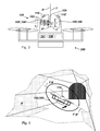
- FIG. 1 shows a first embodiment of a Flying Sensor according to the invention.
- the Flying Sensor comprises an unmanned aerial vehicle (UAV) 200 and a profiler 100, which is adapted to be mounted on the UAV.
- the profiler 100 is configured for operation during a flight of the UAV.
- the profiler 100 has a base 101 and a scanning unit 102, which are shown in figure 1 as being separate elements.
- the base 101 can also be understood as the upper/lower part of the scanning unit 102, such that the profiler and the scanning unit by definition of this application are one structural element.
- the base 101 is designed for being attachable to the UAV 200. That could be achieved, for example, by a snap-in construction, or mounting elements like screws, clamps or straps.
- the base 101 may comprise a battery for energy supply, or the base 101 may be connected to the UAV 200 via an electrical port to obtain electric power from a battery of the UAV, or the base 101 may comprise a battery for energy supply and may be connected to the UAV 200 via an electrical port to provide electric power to a battery of the UAV.
- a port also information may be exchanged, e.g. acceleration data, height data, position data or tilt data.
- the profiler in particular the body 101 (as is exemplarily shown in Figure 1 ) or alternatively the scanning unit 102, comprises a computer 107, a pose sensor 108 and optionally a wireless communication unit 111.
- the pose sensor 108 comprises an Inertial Measuring Unit (IMU) and a Global Navigation Satellite System (GNSS) sensor, which may also be a Pseudo-GNSS sensor for application of the flying sensor in a tunnel where satellite signals cannot be received directly.
- the pose sensor 108 is configured to measure the position and orientation of the flying sensor.
- the scanning unit 102 comprises a motorised shaft 103 which is mounted and motorised, so that it can be rotated under control of the computer 107 about the axis of rotation A.
- a beam deflection unit (deflector) 104 is attached to the shaft 103, and is - in the shown embodiment - protruding out of the scanning unit 102.
- the shown slit of the scanning unit 102 may be sealed by a transparent hood window comprised by the scanning unit 102.
- the scanning unit 102 furthermore comprises a first transmitter 105 and a first receiver 106, which are both shown in figure 1 as being in one box.
- the transmitter 105 and the receiver 106 may, however, also be embodied as two separate units, e.g. wherein the transmission beam T and the reception beam R are separated by a beam splitter, which is known in the art.
- Generated transmission beams T are directed at the deflector 104 which deflects the transmission beams T towards the setting.
- the reflected transmission beams T come back from the environment (by reflection from a surface of the setting) as reception beams R and are deflected by the deflector 104 "back" towards the beam receiver 106.
- a time-of-flight measuring principle a plurality of points is measured. With the distance to the points and the angle of the shaft under which they were measured, LiDAR data are generated by the scanning unit 102, which is also referred to as main scanning unit herein.
- the rotation of the shaft 103 is sensed by an angle encoder or e.g by monitoring the voltage of the motor of the shaft via a hall sensor.
- the base 101 and the scanning unit 102 may be rotatable relative to each other.
- either the base 101 or the scanning unit 102 may comprise a motor (and optionally a gearing) to perform such a relative rotation.
- the rotation may be controlled by the computer 107, and may e.g. be dependent on a current flight path.
- the profiler 100 further has a visual sensor comprising a camera 110 which may be arranged on the scanning unit 102 (as shown), on the base 101 or on the UAV 200.
- the at least one camera has a defined position and defined orientation relative to the point of origin (nodal point) of the profiler.
- the data gathered by the visual sensor are one input for a Simultaneous Localisation and Mapping (SLAM) algorithm (process) performed by the computer 107.
- the other inputs are data gathered by the pose sensor 108 and the LiDAR data gathered by the scanning unit 102.
- SLAM Simultaneous Localisation and Mapping
- a 3D point cloud P of the setting is built up.
- the pose data measured by the pose sensor and the visual data of the visual sensor are helping to store the LiDAR points in a correct spatial correlation.
- the gathered 3D point cloud P may furthermore be coloured or "coated” with texture that has been captured from the topography.
- the profiler according to the invention is significantly light in weight compared to generic devices known from prior art, with having a weight of about 300 grams. Such a weight is unmatched in prior art and makes the profiler especially suitable for usage on an UAV.
- FIG 2 shows the first embodiment of the Flying Sensor shown in figure 1 , while performing a surveying flight along the façade of a row of houses.
- LiDAR Light Detection and Ranging
- Such LiDAR data may be coordinates of the measured single points linked with angle positions of the shaft 103.
- the straight arrow the direction of flight is indicated, and the dashed circular arrow indicates the performed rotation about axis A of a single measuring beam (T, R), i.e. the transmission beam T and the reception beam R are proceeding along the beam axis B, which is rotating.
- the shown beams (T, R) are actually one beam at different rotatory positions.
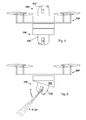
- Figure 3 shows a further embodiment of the Flying Sensor. This configuration may be useful for scanning ceilings in a building or walls in a tunnel. Accordingly, as is not shown in the figures, the profiler 100 may also be mounted at any lateral side of the UAV 200.
- the visual sensor may have more than one camera (110, 110') in order to provide a larger range of view.
- a camera preferably has a wide angle lens providing very small focal length and therewith a coverage of 120°, or up to 180°, or even more.
- a range overlap of two cameras may be used to improve the SLAM process and therewith the construction of the 3D point cloud.
- the scanning unit of the profiler 100 may furthermore have second transmitter 105' and second receiver 106' which are managing a second measuring beam (second reception beam R', second transmission beam T'), which is guided to the opposite direction relative to the first measuring beam (first reception beam R, first transmission beam T).
- the deflector 104 is configured to enable this double side reflection by its inclined surface serving as a mirror from both sides.
- the shaft 103 and the deflector 104 are hollow for allowing the second measuring beam R', T' to pass through and reach the inner side of said mirror. Once reflected, the second transmission beam T' exits the deflector 104 through an incorporated hole or window and in the same manner, second reception beam R' enters the deflector 104 in order to get reflected back to the second receiver 106'.
- Figure 4 shows the Flying Sensor of figure 3 while surveying a tunnel.
- first (T,R) and second (T',R') measuring beam are directed at opposite directions, thereby allowing the scanning unit to collect twice as much points (or the same amount of points in half the time, allowing a faster flying speed of the UAV).
- the data from the visual sensor, from the pose sensor 108 and from the scanning unit 102 are serving as input for the SLAM process which builds up the referenced point cloud P.
- the circular arrow indicates the rotation of the two beams.
- the straight arrow indicates the flight direction of the flying sensor.
- figure 5 shows a Flying Sensor wherein a profiler 100' is mounted on the upper side of a UAV 200 and another profiler 100 is mounted on the bottom side of the UAV 200, in order to provide a 360 degree profiling range lateral to the flight path.
- This configuration may optionally also be interpreted as the profiler 100 comprising an add-on scanning unit 102', wherein no second visual sensor, no second pose sensor and no second computer would exist, but only an additional scanning unit just like the one described above.
- the add-on scanning unit may have its own base or share the base of the main scanning unit.
- each point cloud obtained by an according profiler is registered relative to the other point cloud(s) within the SLAM process, such that - in a single coordinate system - an overall point cloud P is the result.
- the arrangement according to figure 5 can also be understood as being one profiler mounted on the UAV, said profiler comprising two scanning units.
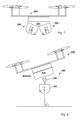
- FIG 6 shows another embodiment of the Flying sensor according to the invention.
- the base 101 of the profiler 100 is designed to let the scanning unit 102 have an inclined orientation with respect to the UAV 200. This can, for example, compensate the tilted orientation of the UAV relative to the ground during a horizontal flight, in order to achieve an orthogonal orientation of the profiler relative to the ground at a specific flight velocity causing a specific inclination of the UAV (compare to figure 8 , where the compensated inclination is variable).
- the base 101 may furthermore comprise servomotors.
- the beam fan T'', R'' is a so called multi-beam which may be generated with the transmitter 105 and/or the deflector 104, wherein each beam of the multi-beam can be distinguished by the receiver 106.
- the circular arrow indicates the rotation of the multi-beam.
- Figure 7 shows a double arrangement of the embodiment of figure 6 .
- the two profilers 100, 100' may be oriented such that their scanning light tracks cross each other. Again, such arrangement may be embodied as one profile with two scanning units, meaning that a pose sensor and/or visual sensor may exist only one time.
- Figure 8 shows a Flying Sensor according to the invention, comprising a joint 109 for swivelling the scanning unit 102, for example passively by gravity alone, or actively by a motor.
- An exemplary purpose may be to achieve an orthogonal orientation of the scanning unit 102 relative to the ground, no matter the current orientation of the UAV, as indicated in figure 7 .
- the joint may also be a gimbal joint (a.k.a. cardan joint) allowing more manoeuvres to the UAV while keeping the orientation of the scanning unit constant.
Landscapes
- Engineering & Computer Science (AREA)
- Physics & Mathematics (AREA)
- Remote Sensing (AREA)
- Radar, Positioning & Navigation (AREA)
- General Physics & Mathematics (AREA)
- Computer Networks & Wireless Communication (AREA)
- Aviation & Aerospace Engineering (AREA)
- Electromagnetism (AREA)
- Mechanical Engineering (AREA)
- Chemical & Material Sciences (AREA)
- Combustion & Propulsion (AREA)
- Automation & Control Theory (AREA)
- Optical Radar Systems And Details Thereof (AREA)
- Control Of Position, Course, Altitude, Or Attitude Of Moving Bodies (AREA)
Abstract
The invention relates to a Flying Sensor which comprises an unmanned aerial vehicle (UAV) and at least one profiler being mounted on the UAV. At least one profiler comprises a base, a scanning unit for providing Light Detection And Ranging (LiDAR) data, the scanning unit mounted on the base and comprising a shaft carrying a deflector, the shaft being mounted in the scanning unit and rotatable about a rotation axis, a first transmitter configured to transmit a first transmission beam via the deflector towards a setting, a first receiver configured to receive a first reception beam reflected from the setting via the deflector, a visual sensor for providing visual data, the visual sensor comprising one or more cameras, a pose sensor for providing pose data, the pose sensor comprising an Inertial Measuring Unit (IMU) and a Global Navigation Satellite System (GNSS) sensor or a Pseudo GNSS sensor, a computer configured to compute a 3D point cloud of the setting with a Simultaneous Localisation and Mapping (SLAM) algorithm based on the LiDar data, the visual data and the pose data.
Description
- The present invention relates to a Flying Sensor according to claim 1.
- For capturing topographies, e.g. for the purpose of surveying, checking or documentation, optical devices are commonly used which work with optical measuring beams for scanning a surface and capturing of the topography by the distance measurement to points on the sensed surface. A suitable scanning device may be a scanner system, in particular a profiler, which allows for capturing a surface structure by guiding a measuring beam in a scanning manner over the surface and by capturing the spatial position of surface points in the scanning area with a distance measurement relating to the points and linking the measurement with angle information gathered at the time of the measuring beam emission. From the angle and distance information, so called range images of the scanned surfaces may be reconstructed.
- A profiler for capturing topographies may also be realised by an electro-optical distance meter, which is guided over a surface area in a scanning manner and which may use laser light.
- The correlation of the measurement points of the distance meter on the one hand, to the surface to be captured on the other hand, may e.g. take place by overlaying the scanned area with a reference model of the surface.
- A laser distance meter as a surface profiler is for example utilised in the "LEICA Pegasus: Two" system of Leica Geosystems AG.
- Fields of application of such surface profilers or systems are e.g. the documentation of structures or the surveying of mines and tunnels. In the latter application, gathering a profile of the hollow space, detecting and measuring of surface variations - like cracks, cavities, gravel nests, detachments or water damages, as well as detecting and measuring of infrastructure - like contact wires, poles and traffic lights - are of particular interest.
- In linearly passable hollow spaces, such as rooms, corridors, mines, tunnels, canyons or alleys, the profiler is usually mounted to a vehicle in such a way that the scanning movement of the measuring beam - in a first scanning direction - takes place about an axis which is essentially parallel to the direction of movement of the vehicle, wherein the direction of movement of the vehicle is a second scanning direction.
- However, in case the ground of said topography is not equipped with an adequate travel way, such as a sealed street or railway tracks, profilers known from prior art are not practicable, or so only under some losses. A similar problem is represented by surveying tasks in canyons, for a vertical surface of a building, or for a wall of rock, wherein a "ground" for linearly guiding the profiler by a vehicle is not available.
- The invention relates to a Flying Sensor which comprises an unmanned aerial vehicle (UAV) and at least one profiler being mounted on the UAV. At least one profiler comprises a base, a scanning unit for providing Light Detection And Ranging (LiDAR) data, the scanning unit mounted on the base and comprising a shaft carrying a deflector, the shaft being mounted in the scanning unit and rotatable about a rotation axis, a first transmitter configured to transmit a first transmission beam via the deflector towards a setting, a first receiver configured to receive a first reception beam reflected from the setting via the deflector, a visual sensor for providing visual data, the visual sensor comprising one or more cameras, a pose sensor for providing pose data, the pose sensor comprising an Inertial Measuring Unit (IMU) and a Global Navigation Satellite System (GNSS) sensor or a Pseudo GNSS sensor, a computer configured to compute a 3D point cloud of the setting with a Simultaneous Localisation and Mapping (SLAM) algorithm based on the LiDar data, the visual data and the pose data.
- The scanning unit may further comprise a second transmitter configured to transmit a second transmission beam via the deflector towards a setting and a second receiver configured to receive a second reception beam reflected from the setting via the deflector, in particular wherein the second transmission beam is transmitted in the opposite direction relative to the first transmission beam.
- At least one of the first transmission beam and the second transmission beam may be a transmission beam fan, in particular wherein at least one of the first reception beam and the second reception beam is a reception beam fan.
- The profiler may further comprise at least one add-on scanning unit configured just as the scanning unit according as described herein.
- The UAV may comprise a plurality of propellers, an aviation unit for providing aviation data, the aviation data comprising data regarding at least one of a height, a velocity, an orientation and a position of the UAV, and a control unit for controlling the propellers based at least on the aviation data.
- The profiler may further comprise a data interface for a connection with the control unit of the UAV, such that the computer of the profiler is provided with the aviation data. The SLAM algorithm may then be further based on the aviation data.
- The profiler may be configured to be mounted by the base, on one of an upper side, a lateral side, and a bottom side of the UAV.
- The scanning unit may be mounted to the base by one of a pivot joint (109), a gimbal joint, and a ball joint, in particular wherein the according joint may be motorized and controllable by the computer.
- The Flying Sensor may further comprise a data storage device for storing at least one of the LiDar data, the visual data, the pose data, the aviation data and the 3D point cloud, the data storage device in particular being ejectable.
- The Flying Sensor may further comprise a wireless communication unit, in particular wherein the computer may be configured to receive commands by a remote control via the wireless communication unit. Said remote control may have a graphical user interface (GUI) configured to show a live image provided by the visual sensor.
- The base may comprise a battery for providing a stand-alone energy supply to the profiler. The base further may comprise a power interface for a connection with the UAV to obtain electric power from a battery of the UAV, or to provide electric power to a battery of the UAV.
- The control unit may be configured to control the propellers further based on the LiDar data, the visual data and the pose data, in particular wherein the control unit is configured to perform at least one of a landing approach, a collision avoidance, hovering, and automatic height control based at least in part on the LiDar data, the visual data and the pose data.
- The at least one camera of the visual sensor may be a regular CCD or CMOS camera known in the art, or in particular one of a thermal infrared camera, and a hyperspectral camera.
- In one embodiment of the Flying Sensor according to invention, the computer is configured to colourise the 3D point cloud by use of at least the visual data. Further, the Flying Sensor may comprise a Magnetometer, a compass, an accelerometer, and/or a gyroscope.
*** - In the following, the invention will be described in detail by referring to exemplary embodiments that are accompanied by figures, in which:
- Fig. 1:
- shows a first embodiment of the profiler according to the invention, and, respectively, a first embodiment of a UAV according to the invention comprising a profiler;
- Fig. 2:
- shows the first embodiment of the profiler according to
figure 1 during a surveying flight, and, respectively, the first embodiment of the UAV according tofigure 1 ; - Fig. 3:
- shows a second embodiment of the profiler according to the invention, and, respectively, a second embodiment of a UAV according to the invention comprising a profiler;
- Fig. 4:
- shows the second embodiment of the profiler during a surveying flight, and, respectively, the second embodiment of the UAV according to
figure 2 ; - Fig. 5:
- shows a third embodiment of the profiler according to the invention comprising two scanning units, and, respectively, a third embodiment of the UAV according to the invention comprising two profilers;
- Fig. 6:
- shows a fourth embodiment of the profiler according to the invention, and, respectively, a forth embodiment of the UAV according to the invention comprising a profiler;
- Fig. 7:
- shows a fifth embodiment of the profiler according to the invention comprising two scanning units, and, respectively, a fifth embodiment of the UAV according to the invention comprising two profilers;
- Fig. 8:
- shows a sixth embodiment of the profiler according to the invention, and, respectively, a sixth embodiment of the UAV according to the invention comprising a profiler;
-
Figure 1 shows a first embodiment of a Flying Sensor according to the invention. The Flying Sensor comprises an unmanned aerial vehicle (UAV) 200 and aprofiler 100, which is adapted to be mounted on the UAV. Theprofiler 100 is configured for operation during a flight of the UAV. - The
profiler 100 has abase 101 and ascanning unit 102, which are shown infigure 1 as being separate elements. In another embodiment, thebase 101 can also be understood as the upper/lower part of thescanning unit 102, such that the profiler and the scanning unit by definition of this application are one structural element. Either way, thebase 101 is designed for being attachable to the UAV 200. That could be achieved, for example, by a snap-in construction, or mounting elements like screws, clamps or straps. Thebase 101 may comprise a battery for energy supply, or thebase 101 may be connected to the UAV 200 via an electrical port to obtain electric power from a battery of the UAV, or thebase 101 may comprise a battery for energy supply and may be connected to theUAV 200 via an electrical port to provide electric power to a battery of the UAV. By said port, also information may be exchanged, e.g. acceleration data, height data, position data or tilt data. - The profiler, in particular the body 101 (as is exemplarily shown in
Figure 1 ) or alternatively thescanning unit 102, comprises acomputer 107, apose sensor 108 and optionally awireless communication unit 111. Thepose sensor 108 comprises an Inertial Measuring Unit (IMU) and a Global Navigation Satellite System (GNSS) sensor, which may also be a Pseudo-GNSS sensor for application of the flying sensor in a tunnel where satellite signals cannot be received directly. Thepose sensor 108 is configured to measure the position and orientation of the flying sensor. - The
scanning unit 102 comprises amotorised shaft 103 which is mounted and motorised, so that it can be rotated under control of thecomputer 107 about the axis of rotation A. A beam deflection unit (deflector) 104 is attached to theshaft 103, and is - in the shown embodiment - protruding out of thescanning unit 102. In another embodiment, however, the shown slit of thescanning unit 102 may be sealed by a transparent hood window comprised by thescanning unit 102. - The
scanning unit 102 furthermore comprises a first transmitter 105 and a first receiver 106, which are both shown infigure 1 as being in one box. The transmitter 105 and the receiver 106 may, however, also be embodied as two separate units, e.g. wherein the transmission beam T and the reception beam R are separated by a beam splitter, which is known in the art. - Generated transmission beams T are directed at the
deflector 104 which deflects the transmission beams T towards the setting. The reflected transmission beams T come back from the environment (by reflection from a surface of the setting) as reception beams R and are deflected by thedeflector 104 "back" towards the beam receiver 106. By a time-of-flight measuring principle, a plurality of points is measured. With the distance to the points and the angle of the shaft under which they were measured, LiDAR data are generated by thescanning unit 102, which is also referred to as main scanning unit herein. For continuously tracking the angle measurement, the rotation of theshaft 103 is sensed by an angle encoder or e.g by monitoring the voltage of the motor of the shaft via a hall sensor. - In a further embodiment, the
base 101 and thescanning unit 102 may be rotatable relative to each other. For this, either the base 101 or thescanning unit 102 may comprise a motor (and optionally a gearing) to perform such a relative rotation. The rotation may be controlled by thecomputer 107, and may e.g. be dependent on a current flight path. - The
profiler 100 further has a visual sensor comprising acamera 110 which may be arranged on the scanning unit 102 (as shown), on the base 101 or on theUAV 200. The at least one camera has a defined position and defined orientation relative to the point of origin (nodal point) of the profiler. The data gathered by the visual sensor are one input for a Simultaneous Localisation and Mapping (SLAM) algorithm (process) performed by thecomputer 107. The other inputs are data gathered by thepose sensor 108 and the LiDAR data gathered by thescanning unit 102. In a combined SLAM process, a 3D point cloud P of the setting is built up. In particular, the pose data measured by the pose sensor and the visual data of the visual sensor are helping to store the LiDAR points in a correct spatial correlation. - With means of the visual data of the
camera 110, the gathered 3D point cloud P may furthermore be coloured or "coated" with texture that has been captured from the topography. - The profiler according to the invention is significantly light in weight compared to generic devices known from prior art, with having a weight of about 300 grams. Such a weight is unmatched in prior art and makes the profiler especially suitable for usage on an UAV.
-
Figure 2 shows the first embodiment of the Flying Sensor shown infigure 1 , while performing a surveying flight along the façade of a row of houses. Thereby, Light Detection and Ranging (LiDAR) data are recorded having a range of more than 180° with regard to the axis A. Such LiDAR data may be coordinates of the measured single points linked with angle positions of theshaft 103. With the straight arrow, the direction of flight is indicated, and the dashed circular arrow indicates the performed rotation about axis A of a single measuring beam (T, R), i.e. the transmission beam T and the reception beam R are proceeding along the beam axis B, which is rotating. The shown beams (T, R) are actually one beam at different rotatory positions. -
Figure 3 shows a further embodiment of the Flying Sensor. This configuration may be useful for scanning ceilings in a building or walls in a tunnel. Accordingly, as is not shown in the figures, theprofiler 100 may also be mounted at any lateral side of theUAV 200. - The visual sensor may have more than one camera (110, 110') in order to provide a larger range of view. A camera preferably has a wide angle lens providing very small focal length and therewith a coverage of 120°, or up to 180°, or even more. A range overlap of two cameras may be used to improve the SLAM process and therewith the construction of the 3D point cloud.
- The scanning unit of the
profiler 100 may furthermore have second transmitter 105' and second receiver 106' which are managing a second measuring beam (second reception beam R', second transmission beam T'), which is guided to the opposite direction relative to the first measuring beam (first reception beam R, first transmission beam T). Thedeflector 104 is configured to enable this double side reflection by its inclined surface serving as a mirror from both sides. Theshaft 103 and thedeflector 104 are hollow for allowing the second measuring beam R', T' to pass through and reach the inner side of said mirror. Once reflected, the second transmission beam T' exits thedeflector 104 through an incorporated hole or window and in the same manner, second reception beam R' enters thedeflector 104 in order to get reflected back to the second receiver 106'. By simultaneously sending out two measuring beams, the resolution of the obtained 3D point cloud can be increased. -
Figure 4 shows the Flying Sensor offigure 3 while surveying a tunnel. As is indicated with the point-dashed line, first (T,R) and second (T',R') measuring beam are directed at opposite directions, thereby allowing the scanning unit to collect twice as much points (or the same amount of points in half the time, allowing a faster flying speed of the UAV). The data from the visual sensor, from thepose sensor 108 and from thescanning unit 102 are serving as input for the SLAM process which builds up the referenced point cloud P. The circular arrow indicates the rotation of the two beams. The straight arrow indicates the flight direction of the flying sensor. - As a further embodiment of the invention,
figure 5 shows a Flying Sensor wherein a profiler 100' is mounted on the upper side of aUAV 200 and anotherprofiler 100 is mounted on the bottom side of theUAV 200, in order to provide a 360 degree profiling range lateral to the flight path. This configuration, however, may optionally also be interpreted as theprofiler 100 comprising an add-on scanning unit 102', wherein no second visual sensor, no second pose sensor and no second computer would exist, but only an additional scanning unit just like the one described above. The add-on scanning unit may have its own base or share the base of the main scanning unit. - In case of more than one profiler mounted to a UAV, each point cloud obtained by an according profiler is registered relative to the other point cloud(s) within the SLAM process, such that - in a single coordinate system - an overall point cloud P is the result.
- As an alternative, the arrangement according to
figure 5 can also be understood as being one profiler mounted on the UAV, said profiler comprising two scanning units. -
Figure 6 shows another embodiment of the Flying sensor according to the invention. Thebase 101 of theprofiler 100 is designed to let thescanning unit 102 have an inclined orientation with respect to theUAV 200. This can, for example, compensate the tilted orientation of the UAV relative to the ground during a horizontal flight, in order to achieve an orthogonal orientation of the profiler relative to the ground at a specific flight velocity causing a specific inclination of the UAV (compare tofigure 8 , where the compensated inclination is variable). To modify the inclination, thebase 101 may furthermore comprise servomotors. - The beam fan T'', R'' is a so called multi-beam which may be generated with the transmitter 105 and/or the
deflector 104, wherein each beam of the multi-beam can be distinguished by the receiver 106. The circular arrow indicates the rotation of the multi-beam. -
Figure 7 shows a double arrangement of the embodiment offigure 6 . The twoprofilers 100, 100' may be oriented such that their scanning light tracks cross each other. Again, such arrangement may be embodied as one profile with two scanning units, meaning that a pose sensor and/or visual sensor may exist only one time. -
Figure 8 shows a Flying Sensor according to the invention, comprising a joint 109 for swivelling thescanning unit 102, for example passively by gravity alone, or actively by a motor. An exemplary purpose may be to achieve an orthogonal orientation of thescanning unit 102 relative to the ground, no matter the current orientation of the UAV, as indicated infigure 7 . The joint may also be a gimbal joint (a.k.a. cardan joint) allowing more manoeuvres to the UAV while keeping the orientation of the scanning unit constant. - Although the invention is illustrated above, partly with reference to some preferred embodiments, it must be understood that numerous modifications and combinations of different features of the embodiments can be made. All of these modifications lie within the scope of the appended claims.
Claims (15)
- A Flying Sensor comprising an unmanned aerial vehicle (UAV) (200) and at least one profiler (100) being mounted on the UAV, wherein the at least one profiler comprises• a base (101),• a scanning unit (102) for providing Light Detection And Ranging (LiDAR) data, the scanning unit mounted on the base and comprising□ a shaft (103) carrying a deflector (104), the shaft being mounted in the scanning unit and rotatable about a rotation axis (A),□ a first transmitter (105) configured to transmit a first transmission beam (T, T'') via the deflector towards a setting,□ a first receiver (106) configured to receive a first reception beam (R, R'') reflected from the setting via the deflector,• a visual sensor for providing visual data, the visual sensor comprising one or more cameras (110, 110'),• a pose sensor (108) for providing pose data, the pose sensor comprising□ an Inertial Measuring Unit (IMU) and□ a Global Navigation Satellite System (GNSS) sensor or a Pseudo GNSS sensor,• a computer (107) configured to compute a 3D point cloud (P) of the setting with a Simultaneous Localisation and Mapping (SLAM) algorithm based on the LiDar data, the visual data and the pose data.
- The Flying Sensor according to claim 1, wherein
the scanning unit (102) comprises• a second transmitter (105') configured to transmit a second transmission beam (T') via the deflector towards a setting and• a second receiver (106') configured to receive a second reception beam (R') reflected from the setting via the deflector,in particular wherein the second transmission beam is transmitted in the opposite direction relative to the first transmission beam. - The Flying Sensor according to claim 1 or 2, wherein at least one of the first transmission beam (T) and the second transmission beam (T') is a transmission beam fan (T''), in particular wherein at least one of the first reception beam (R) and the second reception beam (R') is a reception beam fan (R'').
- The Flying Sensor according to any of the preceding claims, wherein
the profiler further comprises at least one add-on scanning unit (102') configured just as the scanning unit (102) according to any of the preceding claims. - The Flying Sensor according to any of the preceding claims, wherein
the UAV comprises• a plurality of propellers,• an aviation unit for providing aviation data, the aviation data comprising data regarding at least one of□ a height,□ a velocity,□ an orientation and□ a positionof the UAV, and• a control unit for controlling the propellers based at least on the aviation data. - The Flying Sensor according to claim 5, wherein• the profiler further comprises a data interface for a connection with the control unit of the UAV, such that the computer of the profiler is provided with the aviation data, and• the SLAM algorithm is further based on the aviation data.
- The Flying Sensor according to any of the preceding claims, wherein
by the base, the profiler is configured to be mounted on one of• an upper side,• a lateral side, and• a bottom sideof the UAV. - The Flying Sensor according to any of the preceding claims, wherein
the scanning unit (102) is mounted to the base by one of• a pivot joint (109),• a gimbal joint, and• a ball joint,in particular wherein the according joint is motorized and controllable by the computer. - The Flying Sensor according to any of the preceding claims, further comprising
a data storage device for storing at least one of the LiDar data, the visual data, the pose data, the aviation data and the 3D point cloud,
the data storage device in particular being ejectable. - The Flying Sensor according to any of the preceding claims, further comprising
a wireless communication unit (111), in particular wherein the computer is configured to receive commands by a remote control via the wireless communication unit. - The Flying Sensor according to claim 10, wherein the remote control has a graphical user interface (GUI) configured to show a live image provided by the visual sensor.
- The Flying Sensor according to any of the preceding claims, wherein
the base (101) comprises a battery for providing a stand-alone energy supply to the profiler. - The Flying Sensor according to claim 12, wherein the base comprises a power interface for a connection with the UAV• to obtain electric power from a battery of the UAV, or• to provide electric power to a battery of the UAV.
- The Flying Sensor according to any of claims 6 to 13,
wherein
the control unit is configured to control the propellers further based on the LiDar data, the visual data and the pose data,
in particular wherein the control unit is configured to perform at least one of• a landing approach,• a collision avoidance,• hovering, and• automatic height controlbased at least in part on the LiDar data, the visual data and the pose data. - The Flying Sensor according to any of the preceding claims, wherein
the at least one camera of the visual sensor is one of• a thermal infrared camera, and• a hyperspectral camera.
Priority Applications (5)
| Application Number | Priority Date | Filing Date | Title |
|---|---|---|---|
| EP16192915.3A EP3306344A1 (en) | 2016-10-07 | 2016-10-07 | Flying sensor |
| EP17192472.3A EP3306346B1 (en) | 2016-10-07 | 2017-09-21 | Flying sensor |
| US15/727,629 US10640209B2 (en) | 2016-10-07 | 2017-10-08 | Flying sensor |
| CN202110319387.7A CN113029117B (en) | 2016-10-07 | 2017-10-09 | Flight sensor |
| CN201710930141.7A CN107941204B (en) | 2016-10-07 | 2017-10-09 | Flight sensor |
Applications Claiming Priority (1)
| Application Number | Priority Date | Filing Date | Title |
|---|---|---|---|
| EP16192915.3A EP3306344A1 (en) | 2016-10-07 | 2016-10-07 | Flying sensor |
Publications (1)
| Publication Number | Publication Date |
|---|---|
| EP3306344A1 true EP3306344A1 (en) | 2018-04-11 |
Family
ID=57113214
Family Applications (2)
| Application Number | Title | Priority Date | Filing Date |
|---|---|---|---|
| EP16192915.3A Withdrawn EP3306344A1 (en) | 2016-10-07 | 2016-10-07 | Flying sensor |
| EP17192472.3A Active EP3306346B1 (en) | 2016-10-07 | 2017-09-21 | Flying sensor |
Family Applications After (1)
| Application Number | Title | Priority Date | Filing Date |
|---|---|---|---|
| EP17192472.3A Active EP3306346B1 (en) | 2016-10-07 | 2017-09-21 | Flying sensor |
Country Status (3)
| Country | Link |
|---|---|
| US (1) | US10640209B2 (en) |
| EP (2) | EP3306344A1 (en) |
| CN (2) | CN113029117B (en) |
Cited By (9)
| Publication number | Priority date | Publication date | Assignee | Title |
|---|---|---|---|---|
| CN108303710A (en) * | 2018-06-12 | 2018-07-20 | 江苏中科院智能科学技术应用研究院 | Drawing method is built in the more scene positioning of unmanned plane based on three-dimensional laser radar |
| CN108562289A (en) * | 2018-06-07 | 2018-09-21 | 南京航空航天大学 | Quadrotor laser radar air navigation aid in continuous polygon geometry environment |
| CN109358638A (en) * | 2018-09-10 | 2019-02-19 | 南京航空航天大学 | Unmanned plane vision barrier-avoiding method based on distributed maps |
| CN110954101A (en) * | 2019-11-13 | 2020-04-03 | 南昌大学 | Debugging method for laser positioning of unmanned aerial vehicle by using Vicon |
| WO2020124508A1 (en) * | 2018-12-20 | 2020-06-25 | Sz Dji Technology Co. , Ltd. | Position determination method and device based on pose data |
| CN113267788A (en) * | 2021-05-14 | 2021-08-17 | 武汉理工大学 | Data acquisition and processing method and device for laser SLAM |
| WO2022116156A1 (en) * | 2020-12-04 | 2022-06-09 | 深圳市优必选科技股份有限公司 | Visual positioning method, robot, and storage medium |
| CN115167529A (en) * | 2022-09-08 | 2022-10-11 | 北京煜邦电力技术股份有限公司 | Monitoring method and system, unmanned aerial vehicle, mobile terminal and storage medium |
| CN118289245A (en) * | 2024-06-05 | 2024-07-05 | 安徽开源路桥有限责任公司 | Unmanned aerial vehicle laser point cloud high-efficient collection equipment |
Families Citing this family (44)
| Publication number | Priority date | Publication date | Assignee | Title |
|---|---|---|---|---|
| US10737770B2 (en) * | 2015-02-23 | 2020-08-11 | Arif Mir Jalal ogly PASHAYEV | Method and device for increasing the stability and maneuverability of unmanned aerial vehicles (UAV) using a gyroscopic effect |
| JP6688901B2 (en) * | 2016-10-17 | 2020-04-28 | エスゼット ディージェイアイ テクノロジー カンパニー リミテッドSz Dji Technology Co.,Ltd | Three-dimensional shape estimation method, three-dimensional shape estimation system, flying object, program, and recording medium |
| CN116699635A (en) * | 2016-11-10 | 2023-09-05 | 莱卡地球系统公开股份有限公司 | Laser scanner |
| SG11202009468WA (en) * | 2018-03-26 | 2020-10-29 | Univ Singapore Technology & Design | Aerial vehicles, methods of imaging a tunnel and methods of imaging a shaft |
| JP7448485B2 (en) | 2018-05-01 | 2024-03-12 | コモンウェルス サイエンティフィック アンド インダストリアル リサーチ オーガナイゼーション | Methods and systems used in point cloud coloring |
| US20210216071A1 (en) * | 2018-05-25 | 2021-07-15 | Emesent IP Pty Ltd. | Mapping and Control System for an Aerial Vehicle |
| US20210262448A1 (en) * | 2018-06-21 | 2021-08-26 | Vestas Wind Systems A/S | A wind turbine blade, a method of controlling a wind turbine, a control system, and a wind turbine |
| CN109459023B (en) * | 2018-09-18 | 2021-07-16 | 武汉三体机器人有限公司 | Unmanned aerial vehicle vision SLAM-based auxiliary ground robot navigation method and device |
| GB2578289A (en) * | 2018-10-15 | 2020-05-06 | Q Bot Ltd | Sensor apparatus |
| CN109341706B (en) * | 2018-10-17 | 2020-07-03 | 张亮 | Method for manufacturing multi-feature fusion map for unmanned vehicle |
| WO2020088414A1 (en) * | 2018-10-29 | 2020-05-07 | SZ DJI Technology Co., Ltd. | A movable object performing real-time mapping using a payload assembly |
| CN112955713A (en) | 2018-10-29 | 2021-06-11 | 大疆科技股份有限公司 | Techniques for real-time mapping in a movable object environment |
| CN109556598B (en) * | 2018-11-23 | 2021-01-19 | 西安交通大学 | Autonomous mapping and navigation positioning method based on ultrasonic sensor array |
| CN109357772A (en) * | 2018-12-10 | 2019-02-19 | 国网浙江义乌市供电有限公司 | A kind of transformer equipment infrared thermal imaging method of data capture based on SLAM technology |
| EP3671261A1 (en) | 2018-12-21 | 2020-06-24 | Leica Geosystems AG | 3d surveillance system comprising lidar and multispectral imaging for object classification |
| US11099463B2 (en) * | 2019-01-03 | 2021-08-24 | Viettel Group | Two-axis direct drive mechanical mechanism |
| CN111279219A (en) * | 2019-01-09 | 2020-06-12 | 深圳市大疆创新科技有限公司 | Scanning module, distance measuring device and mobile platform |
| EP3693698A1 (en) | 2019-02-05 | 2020-08-12 | Leica Geosystems AG | Measuring device with event-based camera |
| US10979644B2 (en) * | 2019-02-06 | 2021-04-13 | International Business Machines Corporation | 3D surface estimation and prediction to boost fidelity of realtime LiDAR model generation |
| CN110091991A (en) * | 2019-04-15 | 2019-08-06 | 中国建筑第八工程局有限公司 | Gravity self-balancing laser range finder for small drone |
| CN110068335B (en) * | 2019-04-23 | 2021-07-30 | 中国人民解放军国防科技大学 | Unmanned aerial vehicle cluster real-time positioning method and system under GPS rejection environment |
| CN110243381B (en) * | 2019-07-11 | 2020-10-30 | 北京理工大学 | Cooperative sensing monitoring method for air-ground robot |
| CN110501712B (en) * | 2019-09-05 | 2022-06-28 | 北京百度网讯科技有限公司 | Method, device and equipment for determining position attitude data in unmanned driving |
| DE102019129600B4 (en) * | 2019-11-04 | 2023-11-02 | Evitado Technologies GmbH | Portable sensor system |
| CN111288963B (en) * | 2020-02-18 | 2021-11-23 | 中国电建集团西北勘测设计研究院有限公司 | High-risk deformable body GNSS monitoring terminal non-contact throwing device and method |
| CN111624590B (en) * | 2020-05-13 | 2023-07-21 | 飒铂智能科技有限责任公司 | Unmanned aerial vehicle target confirmation method and system |
| US11662056B2 (en) * | 2020-05-25 | 2023-05-30 | Viettel Group | Two-axis direct-drive rotation mechanism for observation device |
| CN112179401A (en) * | 2020-08-20 | 2021-01-05 | 唐山哈船科技有限公司 | Unmanned aerial vehicle detecting system of ocean harbour safety |
| CN112173104A (en) * | 2020-09-03 | 2021-01-05 | 昆明理工大学 | Inspection robot based on four-rotor aircraft |
| IL277712B2 (en) * | 2020-09-29 | 2024-06-01 | Rafael Advanced Defense Systems Ltd | Armed aerial platform |
| CN112381942B (en) * | 2020-11-03 | 2024-04-02 | 华南理工大学 | Building three-dimensional temperature model building method based on unmanned aerial vehicle infrared image |
| CN112558081A (en) * | 2020-11-18 | 2021-03-26 | 国网智能科技股份有限公司 | Laser radar system based on wireless communication network and working method thereof |
| WO2022141537A1 (en) * | 2020-12-31 | 2022-07-07 | 深圳市大疆创新科技有限公司 | Photographing device, gimbal assembly, unmanned aerial vehicle and unmanned aerial vehicle kit |
| IT202100011498A1 (en) * | 2021-05-06 | 2021-08-06 | Dronus S R L | Localization system and relative procedure |
| IT202100011504A1 (en) * | 2021-05-06 | 2021-08-06 | Dronus S R L | Locating system with epicyclic motion and relative procedure |
| IT202100011501A1 (en) * | 2021-05-06 | 2021-08-06 | Dronus S R L | Localization system with tilting motion and relative procedure |
| CN113503875B (en) * | 2021-09-10 | 2021-12-14 | 江苏霆升科技有限公司 | Data association graph establishing method based on extended features |
| RU209611U1 (en) * | 2021-11-23 | 2022-03-17 | Федеральное государственное казенное военное образовательное учреждение высшего образования "ВОЕННАЯ АКАДЕМИЯ МАТЕРИАЛЬНО-ТЕХНИЧЕСКОГО ОБЕСПЕЧЕНИЯ имени генерала армии А.В. Хрулева" Министерства обороны Российской Федерации | Unmanned aerial vehicle for detecting dangerous and foreign objects on the railway |
| CN114435613B (en) * | 2022-02-21 | 2024-03-08 | 山东省国土测绘院 | Camera gesture adjustment and measurement system based on unmanned aerial vehicle survey and drawing |
| CN114802732A (en) * | 2022-05-11 | 2022-07-29 | 沈阳飞机设计研究所扬州协同创新研究院有限公司 | Coaxial double-rotor unmanned aerial vehicle |
| CN114964156B (en) * | 2022-05-19 | 2023-06-20 | 云南数科林业规划设计有限公司 | Stable three-dimensional topography mapping device |
| CN115339629B (en) * | 2022-09-01 | 2023-06-23 | 扬州宇安电子科技有限公司 | Antenna scanning period measuring device capable of automatically adjusting gesture according to surrounding environment change |
| CN115320848B (en) * | 2022-10-13 | 2022-12-30 | 电子科技大学 | Unmanned aerial vehicle system with keep away barrier function |
| CN116908810B (en) * | 2023-09-12 | 2023-12-12 | 天津大学四川创新研究院 | Method and system for measuring earthwork of building by carrying laser radar on unmanned aerial vehicle |
Citations (8)
| Publication number | Priority date | Publication date | Assignee | Title |
|---|---|---|---|---|
| US20120267472A1 (en) * | 2009-06-08 | 2012-10-25 | Elta Systems Ltd. | Air vehicle |
| US20140071234A1 (en) * | 2012-09-10 | 2014-03-13 | Marshall Reed Millett | Multi-dimensional data capture of an environment using plural devices |
| US20140111812A1 (en) * | 2012-05-22 | 2014-04-24 | Korea Institute Of Industrial Technology | 3d scanning system and method of obtaining 3d image |
| WO2015189126A1 (en) * | 2014-06-10 | 2015-12-17 | Fraunhofer-Gesellschaft zur Förderung der angewandten Forschung e.V. | Imaging device having airworthy carrier device |
| US20160033643A1 (en) * | 2012-10-05 | 2016-02-04 | Faro Technologies, Inc. | Registration calculation between three-dimensional (3d) scans based on two-dimensional (2d) scan data from a 3d scanner |
| WO2016123201A1 (en) * | 2015-01-27 | 2016-08-04 | The Trustees Of The University Of Pennsylvania | Systems, devices, and methods for robotic remote sensing for precision agriculture |
| AU2016201290A1 (en) * | 2015-02-27 | 2016-09-15 | Smart Infrastructure Asset Management Australia Research And Development Pty Ltd | Local Positioning System for an Unmanned Aerial Vehicle |
| US20160291136A1 (en) * | 2015-03-31 | 2016-10-06 | Amazon Technologies, Inc. | Modular LIDAR System |
Family Cites Families (8)
| Publication number | Priority date | Publication date | Assignee | Title |
|---|---|---|---|---|
| AT413452B (en) | 2003-11-18 | 2006-03-15 | Riegl Laser Measurement Sys | DEVICE FOR RECORDING AN OBJECT ROOM |
| DE102004033928B4 (en) | 2004-07-14 | 2007-12-20 | Fraunhofer-Gesellschaft zur Förderung der angewandten Forschung e.V. | Scanning device for measuring the contours of an object |
| US9070101B2 (en) * | 2007-01-12 | 2015-06-30 | Fatdoor, Inc. | Peer-to-peer neighborhood delivery multi-copter and method |
| EP2511656A1 (en) * | 2011-04-14 | 2012-10-17 | Hexagon Technology Center GmbH | Measuring system for determining the 3D coordinates of an object surface |
| CN202600150U (en) | 2012-05-17 | 2012-12-12 | 北京必威易激光科技有限公司 | Intelligent low-altitude remote sensing surveying and mapping system |
| JP2014098603A (en) | 2012-11-14 | 2014-05-29 | Toshiba Corp | Three-dimensional model generation device |
| CN104268935A (en) | 2014-09-18 | 2015-01-07 | 华南理工大学 | Feature-based airborne laser point cloud and image data fusion system and method |
| EP3220160B9 (en) * | 2016-03-14 | 2020-03-04 | Riegl Laser Measurement Systems GmbH | Flying device with laser scanner |
-
2016
- 2016-10-07 EP EP16192915.3A patent/EP3306344A1/en not_active Withdrawn
-
2017
- 2017-09-21 EP EP17192472.3A patent/EP3306346B1/en active Active
- 2017-10-08 US US15/727,629 patent/US10640209B2/en active Active
- 2017-10-09 CN CN202110319387.7A patent/CN113029117B/en active Active
- 2017-10-09 CN CN201710930141.7A patent/CN107941204B/en active Active
Patent Citations (8)
| Publication number | Priority date | Publication date | Assignee | Title |
|---|---|---|---|---|
| US20120267472A1 (en) * | 2009-06-08 | 2012-10-25 | Elta Systems Ltd. | Air vehicle |
| US20140111812A1 (en) * | 2012-05-22 | 2014-04-24 | Korea Institute Of Industrial Technology | 3d scanning system and method of obtaining 3d image |
| US20140071234A1 (en) * | 2012-09-10 | 2014-03-13 | Marshall Reed Millett | Multi-dimensional data capture of an environment using plural devices |
| US20160033643A1 (en) * | 2012-10-05 | 2016-02-04 | Faro Technologies, Inc. | Registration calculation between three-dimensional (3d) scans based on two-dimensional (2d) scan data from a 3d scanner |
| WO2015189126A1 (en) * | 2014-06-10 | 2015-12-17 | Fraunhofer-Gesellschaft zur Förderung der angewandten Forschung e.V. | Imaging device having airworthy carrier device |
| WO2016123201A1 (en) * | 2015-01-27 | 2016-08-04 | The Trustees Of The University Of Pennsylvania | Systems, devices, and methods for robotic remote sensing for precision agriculture |
| AU2016201290A1 (en) * | 2015-02-27 | 2016-09-15 | Smart Infrastructure Asset Management Australia Research And Development Pty Ltd | Local Positioning System for an Unmanned Aerial Vehicle |
| US20160291136A1 (en) * | 2015-03-31 | 2016-10-06 | Amazon Technologies, Inc. | Modular LIDAR System |
Non-Patent Citations (2)
| Title |
|---|
| "SCAN-COPTER Commercial brochure", 3 May 2014 (2014-05-03), XP055204359, Retrieved from the Internet <URL:http://www.scan-copter.com/SC_datasheet.pdf> [retrieved on 20150723] * |
| PETER DORNINGER ET AL: "Scan-Copter 2.0 a product of 4D-IT GmbH & von-oben e.U. High-Quality 3D Documentation supported by UAV Strength by Cooperation 3D Documentation Multimedia Applications Data Processing Sensor Integration UAV Development Professional Photographer Documentation Multimedia Productions", 14 May 2014 (2014-05-14), XP055204327, Retrieved from the Internet <URL:http://scan-copter.4d-it.com/SC_info.pdf> [retrieved on 20150723] * |
Cited By (12)
| Publication number | Priority date | Publication date | Assignee | Title |
|---|---|---|---|---|
| CN108562289A (en) * | 2018-06-07 | 2018-09-21 | 南京航空航天大学 | Quadrotor laser radar air navigation aid in continuous polygon geometry environment |
| CN108562289B (en) * | 2018-06-07 | 2021-11-26 | 南京航空航天大学 | Laser radar navigation method for four-rotor aircraft in continuous multilateral geometric environment |
| CN108303710A (en) * | 2018-06-12 | 2018-07-20 | 江苏中科院智能科学技术应用研究院 | Drawing method is built in the more scene positioning of unmanned plane based on three-dimensional laser radar |
| CN109358638A (en) * | 2018-09-10 | 2019-02-19 | 南京航空航天大学 | Unmanned plane vision barrier-avoiding method based on distributed maps |
| WO2020124508A1 (en) * | 2018-12-20 | 2020-06-25 | Sz Dji Technology Co. , Ltd. | Position determination method and device based on pose data |
| CN110954101A (en) * | 2019-11-13 | 2020-04-03 | 南昌大学 | Debugging method for laser positioning of unmanned aerial vehicle by using Vicon |
| WO2022116156A1 (en) * | 2020-12-04 | 2022-06-09 | 深圳市优必选科技股份有限公司 | Visual positioning method, robot, and storage medium |
| CN113267788A (en) * | 2021-05-14 | 2021-08-17 | 武汉理工大学 | Data acquisition and processing method and device for laser SLAM |
| CN113267788B (en) * | 2021-05-14 | 2023-12-26 | 武汉理工大学 | Data acquisition and processing method and device for laser SLAM |
| CN115167529A (en) * | 2022-09-08 | 2022-10-11 | 北京煜邦电力技术股份有限公司 | Monitoring method and system, unmanned aerial vehicle, mobile terminal and storage medium |
| CN115167529B (en) * | 2022-09-08 | 2022-12-13 | 北京煜邦电力技术股份有限公司 | Monitoring method and system, unmanned aerial vehicle, mobile terminal and storage medium |
| CN118289245A (en) * | 2024-06-05 | 2024-07-05 | 安徽开源路桥有限责任公司 | Unmanned aerial vehicle laser point cloud high-efficient collection equipment |
Also Published As
| Publication number | Publication date |
|---|---|
| CN113029117B (en) | 2023-06-02 |
| EP3306346B1 (en) | 2023-05-10 |
| CN107941204B (en) | 2021-04-27 |
| CN113029117A (en) | 2021-06-25 |
| US10640209B2 (en) | 2020-05-05 |
| US20180099744A1 (en) | 2018-04-12 |
| EP3306346A1 (en) | 2018-04-11 |
| CN107941204A (en) | 2018-04-20 |
Similar Documents
| Publication | Publication Date | Title |
|---|---|---|
| US10640209B2 (en) | Flying sensor | |
| US20220124303A1 (en) | Methods and systems for selective sensor fusion | |
| US20230365129A1 (en) | Apparatus and methods for obstacle detection | |
| US9671094B2 (en) | Laser scanning apparatus and method of use | |
| JP7077013B2 (en) | 3D information processing unit, device equipped with 3D information processing unit, unmanned aerial vehicle, notification device, moving object control method using 3D information processing unit, and program for moving object control processing | |
| JP5882951B2 (en) | Aircraft guidance system and aircraft guidance method | |
| ES2876449T3 (en) | Multi-sensor environment mapping | |
| JP2018055695A (en) | Method of controlling unmanned aircraft in given environment, method for generating map of given environment, system, program, and communication terminal | |
| US20200117197A1 (en) | Obstacle detection assembly for a drone, drone equipped with such an obstacle detection assembly and obstacle detection method | |
| Holz et al. | Towards multimodal omnidirectional obstacle detection for autonomous unmanned aerial vehicles | |
| JP2019016197A (en) | Moving entity induction system | |
| JP2022057277A (en) | Surveying system | |
| CN110945510A (en) | Method for spatial measurement by means of a measuring vehicle | |
| JP6681105B2 (en) | Flying body | |
| JP2023140509A (en) | surveying system | |
| JP6631900B1 (en) | Flying object | |
| US20220230550A1 (en) | 3d localization and mapping systems and methods | |
| JP2023048409A (en) | Survey system | |
| JP2023140508A (en) | surveying system |
Legal Events
| Date | Code | Title | Description |
|---|---|---|---|
| PUAI | Public reference made under article 153(3) epc to a published international application that has entered the european phase |
Free format text: ORIGINAL CODE: 0009012 |
|
| AK | Designated contracting states |
Kind code of ref document: A1 Designated state(s): AL AT BE BG CH CY CZ DE DK EE ES FI FR GB GR HR HU IE IS IT LI LT LU LV MC MK MT NL NO PL PT RO RS SE SI SK SM TR |
|
| AX | Request for extension of the european patent |
Extension state: BA ME |
|
| STAA | Information on the status of an ep patent application or granted ep patent |
Free format text: STATUS: THE APPLICATION IS DEEMED TO BE WITHDRAWN |
|
| 18D | Application deemed to be withdrawn |
Effective date: 20181012 |