EP3306074A2 - Engine unit and straddled vehicle - Google Patents
Engine unit and straddled vehicle Download PDFInfo
- Publication number
- EP3306074A2 EP3306074A2 EP17193476.3A EP17193476A EP3306074A2 EP 3306074 A2 EP3306074 A2 EP 3306074A2 EP 17193476 A EP17193476 A EP 17193476A EP 3306074 A2 EP3306074 A2 EP 3306074A2
- Authority
- EP
- European Patent Office
- Prior art keywords
- detection
- rotor
- detection object
- variation
- control device
- Prior art date
- Legal status (The legal status is an assumption and is not a legal conclusion. Google has not performed a legal analysis and makes no representation as to the accuracy of the status listed.)
- Granted
Links
- 238000001514 detection method Methods 0.000 claims abstract description 383
- 238000004804 winding Methods 0.000 claims abstract description 267
- 239000007858 starting material Substances 0.000 claims abstract description 92
- 230000001133 acceleration Effects 0.000 claims abstract description 52
- 230000005291 magnetic effect Effects 0.000 claims description 81
- 238000002485 combustion reaction Methods 0.000 claims description 29
- 230000008859 change Effects 0.000 claims description 16
- 239000000696 magnetic material Substances 0.000 claims description 5
- 230000001747 exhibiting effect Effects 0.000 claims description 2
- 230000006866 deterioration Effects 0.000 abstract description 6
- 230000001629 suppression Effects 0.000 abstract description 4
- 230000000875 corresponding effect Effects 0.000 description 180
- 238000003708 edge detection Methods 0.000 description 16
- 230000005540 biological transmission Effects 0.000 description 8
- 230000001276 controlling effect Effects 0.000 description 7
- 230000004907 flux Effects 0.000 description 7
- 239000000446 fuel Substances 0.000 description 7
- XEEYBQQBJWHFJM-UHFFFAOYSA-N Iron Chemical compound [Fe] XEEYBQQBJWHFJM-UHFFFAOYSA-N 0.000 description 6
- 230000000630 rising effect Effects 0.000 description 6
- 230000007246 mechanism Effects 0.000 description 5
- 230000006835 compression Effects 0.000 description 4
- 238000007906 compression Methods 0.000 description 4
- 238000010586 diagram Methods 0.000 description 4
- 230000006870 function Effects 0.000 description 3
- 229910052742 iron Inorganic materials 0.000 description 3
- 230000035945 sensitivity Effects 0.000 description 3
- 238000006243 chemical reaction Methods 0.000 description 2
- 239000003638 chemical reducing agent Substances 0.000 description 2
- 239000003302 ferromagnetic material Substances 0.000 description 2
- 230000005669 field effect Effects 0.000 description 2
- 230000014509 gene expression Effects 0.000 description 2
- 230000006872 improvement Effects 0.000 description 2
- 238000002347 injection Methods 0.000 description 2
- 239000007924 injection Substances 0.000 description 2
- 230000004048 modification Effects 0.000 description 2
- 238000012986 modification Methods 0.000 description 2
- 230000002035 prolonged effect Effects 0.000 description 2
- 239000004065 semiconductor Substances 0.000 description 2
- 238000004904 shortening Methods 0.000 description 2
- 230000006978 adaptation Effects 0.000 description 1
- 230000004075 alteration Effects 0.000 description 1
- 238000001816 cooling Methods 0.000 description 1
- 230000002596 correlated effect Effects 0.000 description 1
- 230000000694 effects Effects 0.000 description 1
- 239000002184 metal Substances 0.000 description 1
- 229910052751 metal Inorganic materials 0.000 description 1
- 238000000034 method Methods 0.000 description 1
- 230000008569 process Effects 0.000 description 1
- 238000009877 rendering Methods 0.000 description 1
- 230000004044 response Effects 0.000 description 1
- 238000007493 shaping process Methods 0.000 description 1
Images


Classifications
-
- H—ELECTRICITY
- H02—GENERATION; CONVERSION OR DISTRIBUTION OF ELECTRIC POWER
- H02P—CONTROL OR REGULATION OF ELECTRIC MOTORS, ELECTRIC GENERATORS OR DYNAMO-ELECTRIC CONVERTERS; CONTROLLING TRANSFORMERS, REACTORS OR CHOKE COILS
- H02P6/00—Arrangements for controlling synchronous motors or other dynamo-electric motors using electronic commutation dependent on the rotor position; Electronic commutators therefor
- H02P6/14—Electronic commutators
- H02P6/16—Circuit arrangements for detecting position
-
- F—MECHANICAL ENGINEERING; LIGHTING; HEATING; WEAPONS; BLASTING
- F02—COMBUSTION ENGINES; HOT-GAS OR COMBUSTION-PRODUCT ENGINE PLANTS
- F02N—STARTING OF COMBUSTION ENGINES; STARTING AIDS FOR SUCH ENGINES, NOT OTHERWISE PROVIDED FOR
- F02N11/00—Starting of engines by means of electric motors
- F02N11/08—Circuits or control means specially adapted for starting of engines
- F02N11/0848—Circuits or control means specially adapted for starting of engines with means for detecting successful engine start, e.g. to stop starter actuation
-
- G—PHYSICS
- G01—MEASURING; TESTING
- G01P—MEASURING LINEAR OR ANGULAR SPEED, ACCELERATION, DECELERATION, OR SHOCK; INDICATING PRESENCE, ABSENCE, OR DIRECTION, OF MOVEMENT
- G01P3/00—Measuring linear or angular speed; Measuring differences of linear or angular speeds
- G01P3/42—Devices characterised by the use of electric or magnetic means
- G01P3/44—Devices characterised by the use of electric or magnetic means for measuring angular speed
- G01P3/48—Devices characterised by the use of electric or magnetic means for measuring angular speed by measuring frequency of generated current or voltage
- G01P3/481—Devices characterised by the use of electric or magnetic means for measuring angular speed by measuring frequency of generated current or voltage of pulse signals
- G01P3/487—Devices characterised by the use of electric or magnetic means for measuring angular speed by measuring frequency of generated current or voltage of pulse signals delivered by rotating magnets
-
- F—MECHANICAL ENGINEERING; LIGHTING; HEATING; WEAPONS; BLASTING
- F02—COMBUSTION ENGINES; HOT-GAS OR COMBUSTION-PRODUCT ENGINE PLANTS
- F02N—STARTING OF COMBUSTION ENGINES; STARTING AIDS FOR SUCH ENGINES, NOT OTHERWISE PROVIDED FOR
- F02N11/00—Starting of engines by means of electric motors
- F02N11/04—Starting of engines by means of electric motors the motors being associated with current generators
-
- F—MECHANICAL ENGINEERING; LIGHTING; HEATING; WEAPONS; BLASTING
- F02—COMBUSTION ENGINES; HOT-GAS OR COMBUSTION-PRODUCT ENGINE PLANTS
- F02N—STARTING OF COMBUSTION ENGINES; STARTING AIDS FOR SUCH ENGINES, NOT OTHERWISE PROVIDED FOR
- F02N11/00—Starting of engines by means of electric motors
- F02N11/08—Circuits or control means specially adapted for starting of engines
- F02N2011/0881—Components of the circuit not provided for by previous groups
- F02N2011/0896—Inverters for electric machines, e.g. starter-generators
-
- F—MECHANICAL ENGINEERING; LIGHTING; HEATING; WEAPONS; BLASTING
- F02—COMBUSTION ENGINES; HOT-GAS OR COMBUSTION-PRODUCT ENGINE PLANTS
- F02N—STARTING OF COMBUSTION ENGINES; STARTING AIDS FOR SUCH ENGINES, NOT OTHERWISE PROVIDED FOR
- F02N2200/00—Parameters used for control of starting apparatus
- F02N2200/02—Parameters used for control of starting apparatus said parameters being related to the engine
- F02N2200/021—Engine crank angle
-
- F—MECHANICAL ENGINEERING; LIGHTING; HEATING; WEAPONS; BLASTING
- F02—COMBUSTION ENGINES; HOT-GAS OR COMBUSTION-PRODUCT ENGINE PLANTS
- F02N—STARTING OF COMBUSTION ENGINES; STARTING AIDS FOR SUCH ENGINES, NOT OTHERWISE PROVIDED FOR
- F02N2250/00—Problems related to engine starting or engine's starting apparatus
- F02N2250/04—Reverse rotation of the engine
-
- F—MECHANICAL ENGINEERING; LIGHTING; HEATING; WEAPONS; BLASTING
- F02—COMBUSTION ENGINES; HOT-GAS OR COMBUSTION-PRODUCT ENGINE PLANTS
- F02P—IGNITION, OTHER THAN COMPRESSION IGNITION, FOR INTERNAL-COMBUSTION ENGINES; TESTING OF IGNITION TIMING IN COMPRESSION-IGNITION ENGINES
- F02P7/00—Arrangements of distributors, circuit-makers or -breakers, e.g. of distributor and circuit-breaker combinations or pick-up devices
- F02P7/06—Arrangements of distributors, circuit-makers or -breakers, e.g. of distributor and circuit-breaker combinations or pick-up devices of circuit-makers or -breakers, or pick-up devices adapted to sense particular points of the timing cycle
- F02P7/067—Electromagnetic pick-up devices, e.g. providing induced current in a coil
- F02P7/0675—Electromagnetic pick-up devices, e.g. providing induced current in a coil with variable reluctance, e.g. depending on the shape of a tooth
-
- H—ELECTRICITY
- H02—GENERATION; CONVERSION OR DISTRIBUTION OF ELECTRIC POWER
- H02P—CONTROL OR REGULATION OF ELECTRIC MOTORS, ELECTRIC GENERATORS OR DYNAMO-ELECTRIC CONVERTERS; CONTROLLING TRANSFORMERS, REACTORS OR CHOKE COILS
- H02P6/00—Arrangements for controlling synchronous motors or other dynamo-electric motors using electronic commutation dependent on the rotor position; Electronic commutators therefor
- H02P6/08—Arrangements for controlling the speed or torque of a single motor
Landscapes
- Engineering & Computer Science (AREA)
- General Physics & Mathematics (AREA)
- Combustion & Propulsion (AREA)
- Mechanical Engineering (AREA)
- General Engineering & Computer Science (AREA)
- Physics & Mathematics (AREA)
- Chemical & Material Sciences (AREA)
- Power Engineering (AREA)
- Control Of Motors That Do Not Use Commutators (AREA)
- Electric Propulsion And Braking For Vehicles (AREA)
- Control Of Electric Motors In General (AREA)
- Control Of Ac Motors In General (AREA)
- Connection Of Motors, Electrical Generators, Mechanical Devices, And The Like (AREA)
- Permanent Magnet Type Synchronous Machine (AREA)
Abstract
Description
- The present teaching relates to an engine unit and a straddled vehicle.
- For example,
WO 2015/093554 A1 shows an engine unit mountable to a straddled vehicle. The engine unit includes a four-stroke engine body, a starter motor, and a control device. The starter motor includes a rotor and a stator. The rotor is rotated along with rotation of a crankshaft of the engine body. The stator includes stator windings. The control device includes a plurality of detection object parts and a rotor position detection device. The plurality of detection object parts are provided on an outer surface of the rotor. The rotor position detection device includes a detection-purpose winding. As the detection object parts move along with rotation of the rotor, a magnetic state changes so that an electrical signal flowing in the detection-purpose winding varies. The control device firstly performs on/off-operation of switching parts at predefined timings. As a result of the on/off-operation of the switching parts, a current flowing in the stator windings varies. The control device then performs on/off-operation of the switching parts at timings that are based on a variation in the electrical signal flowing in the detection-purpose winding. Thus, the control device is able to accelerate forward rotation of the crankshaft. - The rotor position detection device of
WO 2015/093554 A1 , which performs detection with the detection-purpose winding, has an excellent heat resistance. It is therefore not necessary that a special heat shield structure for protecting the rotor position detection device be provided in the engine unit. Accordingly, the engine unit ofWO 2015/093554 A1 improves early-start ability of the four-stroke engine and mountability thereof to vehicle, irrespective of how the engine is cooled. - In an engine unit, there is a demand for further improvement in early-start ability with suppression of deterioration in mountability to vehicle.
- An object of the present teaching is to provide an engine unit having its early-start ability further improved with suppression of deterioration in mountability to vehicle. Another object of the present teaching is to provide a vehicle equipped with such an engine unit.
- The present inventors conducted studies on engine start. A conceivable way to improve early-start ability is to accelerate forward rotation of a crankshaft at an early stage. For example, it is conceivable that a cycle of variation in a current flowing in stator windings is shortened at an early stage.
- Shortening the cycle of variation in the current flowing in the stator windings at an early stage, however, makes it likely that rotation of a rotor, which rotates in conjunction with a crankshaft, cannot follow a varication in the current flowing in the stator windings.
- For example, in a case where rotation of the rotor fails to follow a variation in the current flowing in the stator windings, a series of operations need be redone. Here, if it takes time to detect a situation where rotation of the rotor fails to follow, a time period before the redo of operations is started is prolonged. A time period before engine start is prolonged.
- Simply increasing output power characteristics of a starter motor is one conceivable way to accelerate forward rotation of the crankshaft at an early stage. Increasing the output power characteristics of the starter motor requires a size increase of the starter motor or a battery. This deteriorates mountability to vehicle.
- The present inventors conducted studies on how to accelerate forward rotation of the crankshaft at an early stage without increasing the output power characteristics of the starter motor.
- At a time of engine start, the rotor of the starter motor and the crankshaft start to rotate from their stopped state. At the time of engine start, therefore, the rotation speed of the crankshaft and the rotor is low.
- On/off operation of switching parts is controlled based mainly on a timing at which a signal varies, the signal indicating detection of a detection object part which is moving along with forward rotation of the rotor. A timing of detection of the detection object part corresponds to a specific position of the rotor. At a time of engine start, unlike while the starter motor is generating power for example, the rotor has a low rotation speed, which prolongs the interval of detection of the detection object part. The accuracy of a rotor position control is likely to be low accordingly.
- The present inventors considered more precisely controlling a variation in a current flowing in the stator windings.
- To increase the accuracy of controlling, the present inventors considered increasing the number of detection object parts arranged in the rotor. The detection object part is, for example, a protruding portion arranged on an outer side of a yoke of the rotor.
- A waveform of an electrical signal variation corresponding to a detection object part that is added for the number increase is identical to a waveform of an electrical signal variation corresponding to a detection object part that is originally provided before the number increase. It is therefore difficult to distinguish the electrical signal variations from each other. For example, it is difficult to determine which of a control corresponding to the detection object part that is originally provided and a control corresponding to the detection object part that is added is to be performed at a timing when a certain electrical signal variation after the rotor starts rotation.
- The present inventors also considered increasing the number of detection devices. For example, providing a plurality of detection devices at different positions enables different position information to be obtained from a single detection object part.
- Increasing the number of detection devices, however, leads to an increase in the number of component parts of the engine unit. Moreover, a space for arranging the added detection devices needs to be ensured in the engine unit. In conclusion, increasing the number of detection devices, as well as providing means for detecting the position at a high accuracy for example, deteriorates mountability of the engine unit to the straddled vehicle.
- The present inventors conducted more detailed studies on a signal indicating that a detection device detects a detection object part.
- The detection device outputs a signal according to passing of the detection object part through a position where the detection device performs detection. More specifically, an electrical signal flowing in a detection-purpose winding indicates a range from start to termination of passing of the detection object part. A signal variation indicating start of passing of the detection object part corresponds to a forward end of the detection object part with respect to a direction in which the detection object part moves. A signal variation indicating termination of the passing corresponds to a rearward end of the detection object part.
- The present inventors conceived of using both a signal variation corresponding to the forward end of one detection object part and a signal variation corresponding to the rearward end of the same detection object part. Accordingly, twice the information is obtained about a rotor state.
- In addition, a signal variation corresponding to the forward end of the detection object part and a signal variation corresponding to the rearward end of the detection object part appear in the form of different types of variations in the detection-purpose winding. It is therefore easy to distinguish the signal variation corresponding to the forward end of the detection object part from the signal variation corresponding to the rearward end of the detection object part. The distinction is made because a timing of a variation that is newly obtained is recognized as a timing applied to a rotor position different from a rotor position to which a timing of a previous variation is applied. The accuracy of controlling is improved accordingly. This enables a more precise control of a variation in the current flowing in the stator windings.
- As above, a more precise control is enabled by using both the signal variation corresponding to the forward end of the detection object part and the signal variation corresponding to the rearward end of the detection object part.
- Using both of the signal variations corresponding to the forward and rearward ends of the detection object part makes it easy that a variation in the current supplied to the stator windings is precisely adapted to rotation of the rotor. Particularly at a time of engine start, the rotation speed of the rotor is low. At this time, followability of rotation of the rotor can be improved by the precise control using both of the signal variations corresponding to the forward and rearward ends. This makes it possible that, for example, a cycle of performing on/off operation of the switching part be shortened at an early stage, to accelerate rotation of the rotor at an early stage.
- In addition, for example, using both of the signal variations corresponding to the forward and rearward ends of the detection object part also allows desynchronization (step out) of the rotor to be detected at an early stage. In a case of desynchronization of the rotor, therefore, a control of the current supplied to the stator winding can be redone at an early stage. The redoing at the early stage improves the followability of rotation of the rotor.
- The present teaching is a teaching accomplished based on the findings described above.
- To solve the problems described above, the present teaching adopts the following configurations.
- (1) An engine unit mountable to a straddled vehicle, the engine unit including:
- a four-stroke engine body in which a high-load region and a low-load region occur during four strokes in a state where combustion is stopped, the high-load region having a high load on rotation of the crankshaft, the low-load region having a lower load on rotation of the crankshaft than that of the high-load region;
- a starter motor including a stator, a rotor, and a plurality of detection object parts, the stator having a stator core that is provided with a plurality of teeth arranged at intervals with respect to a circumferential direction and multi-phase stator windings that are wound on the plurality of teeth, the rotor having a permanent magnet part provided outside the stator with respect to a radial direction and a back yoke portion provided outside the permanent magnet part with respect to the radial direction, the permanent magnet part having a plurality of magnetic pole faces arranged in the circumferential direction on a surface of the permanent magnet part opposed to the stator, the rotor configured to be rotated along with rotation of the crankshaft, the plurality of detection object parts provided on an outer surface of the rotor and arranged at intervals with respect to the circumferential direction, each of the plurality of detection object parts extending from its forward end toits rearward end with respect to a direction of its movement along with rotation of the rotor;
- a rotor position detection device arranged at a position allowed to be opposed to each of the plurality of detection object parts with an air gap therebetween during rotation of the rotor, the rotor position detection device including a detection-purpose winding provided separately from the stator winding, the detection-purpose winding configured such that an electrical signal flows therethrough, the electrical signal exhibiting different waveforms between when corresponding to the forward end and when corresponding to the rearward end, the difference caused due to a magnetic state change caused by movement of the plurality of detection object parts;
- an inverter connected to the multi-phase stator windings and including a plurality of switching parts that control, by on/off-operation thereof, a current flowing between the multi-phase stator windings and a battery; and
- a control device that controls an operation of the starter motor by controlling the plurality of switching parts,
- the control device configured to shift from a start control mode to an acceleration control mode, the start control mode being a mode for performing on/off-operation of the plurality of switching parts at predefined timings in a state where the crankshaft is stopped such that a current is supplied to the multi-phase stator windings to start forward rotation of the crankshaft, the acceleration control mode being a mode for performing on/off-operation of the plurality of switching parts at timings based on an electrical signal flowing in the detection-purpose winding of the rotor position detection device such that a current is supplied to the multi-phase stator windings to accelerate forward rotation of the crankshaft, the electrical signal varying due to a magnetic state change caused by movement of the plurality of detection object parts along with forward rotation of the crankshaft, the control device configured to cause rotation of the rotor to follow a variation in a current flowing in the multi-phase stator windings by controlling on/off-operation of the plurality of switching parts based on both a timing of a variation corresponding to the forward end of the detection object part and a timing of a variation corresponding to the rearward end of the detection object part among variations in the electrical signal flowing in the detection-purpose winding in at least part of a time period during which at least one of the start control mode and the acceleration control mode is performed.
a plurality of detection object parts are provided on an outer surface of the rotor. Each of the detection object parts has a forward end and a rearward end. The rotor position detection device is arranged at a position allowed to be opposed to each of the plurality of detection object parts with an air gap therebetween during rotation of the rotor. The rotor position detection device includes a detection-purpose winding provided separately from the stator winding. The detection-purpose winding allows an electrical signal to flow therethrough when opposed to the plurality of detection object parts during rotation of the rotor. The electrical signal contains a variation corresponding to the forward end of the detection object part and a variation corresponding to the rearward end of the detection object part. The control device causes rotation of the rotor to follow a variation in a current flowing in the multi-phase stator windings by controlling on/off-operation of the switching parts based on both a timing of a variation corresponding to the forward end of the detection object part and a timing of a variation corresponding to the rearward end of the detection object part.
The control device shifts from a start control mode to an acceleration control mode. In the start control mode, the control device performs on/off-operation of the switching parts at predefined timings such that a current is supplied to the multi-phase stator windings to start forward rotation of the crankshaft from its stopped state. In the acceleration control mode, the control device performs on/off-operation of the switching parts at timings based on an electrical signal flowing in the detection-purpose winding such that a current is supplied to the multi-phase stator windings to accelerate forward rotation of the crankshaft.
The control device controls on/off-operation of the switching parts based on both a timing of a variation corresponding to the forward end and a timing of a variation corresponding to the rearward end among variations in the electrical signal. Among variations in the electrical signal flowing in the detection-purpose winding, a variation corresponding to the forward end and a variation corresponding to the rearward end are detected as different types of variations. A variation corresponding to the forward end and a variation corresponding to the rearward end is easily distinguished from each other. It is therefore possible that a control at a timing of a variation corresponding to the rearward end is performed distinctively from a control at a timing of a variation corresponding to the forward end. For example, as for a control of a current variation in the stator winding, a control at a timing of a variation corresponding to the rearward end can be applied to a control in a phase different from that for the forward end. As a result, the control device is able to control the switching parts at a timing of a variation in the electrical signal corresponding to each of the forward and rearward ends. The switching parts are controlled with a high accuracy.
The control with a high accuracy improves followability of rotation of the rotor to a current supplied to the stator windings. Particularly when the rotation speed of the rotor is low at a time of engine start, the current supplied to the stator windings is controlled with a high accuracy based on signal timings corresponding to both of the forward and rearward ends, which improves the followability of rotation of the rotor. Thus, the rotor is likely to follow even though a cycle of variation in the current supplied to the stator windings is shortened at an early stage for the purpose of increasing the rotation speed of the starter motor at an early stage. Accordingly, rotation of the crankshaft can be accelerated at an early stage.
As a result, in a four-stroke engine body having a high-load region and a low-load region and having such characteristics that a torque required for rotating a crankshaft largely varies, it is easy for the crankshaft to overcome a load in the high-load region in a shorter time.
The electrical signal containing both a variation corresponding to the forward end and a variation corresponding to the rearward end is outputted from a single rotor position detection device. This enables a control to be performed with a high accuracy while suppressing an increase in the number of component parts.
Accordingly, the configuration of (1) is able to improve early-start ability of the engine while suppressing a deterioration in mountability to vehicle. - (2) The engine unit of (1), in which
in at least part of a time period during which the acceleration control mode is performed, the control device performs on/off-operation of the plurality of switching parts so as to control a current flowing in the stator winding such that a variation in the current is repeated, and performs on/off-operation of the plurality of switching parts so as to correct a variation phase of the current at both a timing of a variation corresponding to the forward end of the detection object part and a timing of a variation corresponding to the rearward end of the detection object part among variations in the electrical signal flowing in the detection-purpose winding.
In the configuration of (2), among variations in the electrical signal flowing in the detection-purpose winding, a variation corresponding to the forward end and a variation corresponding to the rearward end are detected as different types of variations. It is easy to distinguish an electrical signal variation corresponding to the forward end and an electrical signal variation corresponding to the rearward end from each other. It is therefore possible that, in phases of the variation in the current flowing in the stator winding, a phase in a region corresponding to the forward end is corrected at a timing of a variation corresponding to the forward end of the detection object part, while in phases of the variation in the current flowing in the stator winding, a phase in a region corresponding to the rearward end is corrected with a high accuracy at a timing of a variation corresponding to the forward end of the detection object part.
In a case of, for example, increasing the number of detection object parts provided in the rotor to increase the frequency of an electrical signal variation corresponding to one end of the detection object part, variations appear as the same type of variation. It is not easy to distinguish a region to which each variation is applied. It is therefore difficult to use these variations to correct the variation phase of the current flowing in the stator winding.
In this respect, the configuration of (2) enables the phase of the current flowing in the stator winding to be controlled more precisely by using both of the forward and rearward ends of the detection object part. Thus, rotation of the rotor is likely to follow even though a cycle of variation in the current flowing in the stator winding is shortened. Accordingly, the early-start ability of the engine is further improved. - (3) The engine unit of (1) or (2), in which
in at least part of at least one of time periods during which the start control mode and the acceleration control mode are performed, the control device performs on/off-operation of the plurality of switching parts so as to control a current flowing in the stator winding such that a cycle of variation in the current changes over time, and detects occurrence of desynchronization of the rotor by comparing, against a variation phase of the current flowing in the stator winding, both a timing of a variation corresponding to the forward end of the detection object part and a timing of a variation corresponding to the rearward end of the detection object part among variations in the electrical signal flowing in the detection-purpose winding.
The rotor, which is rotated along with rotation of the crankshaft, has a high load on rotation. Particularly in a four-stroke engine body having a high-load region and a low-load region, a load in the high-load region increases by a large increment. If desynchronization occurs, acceleration of rotation of the crankshaft cannot be continued easily.
In the configuration of (3), among variations in the electrical signal flowing in the detection-purpose winding, a variation corresponding to the forward end of the detection object part and a variation corresponding to the rearward end of the detection object part are detected as different types of variations. It is easy to distinguish a variation corresponding to the forward end and a variation corresponding to the rearward end from each other. It is therefore possible to adopt distinct conditions in comparing, against a variation phase of the current flowing in the stator winding, both a timing of a variation corresponding to the forward end and a timing of a variation corresponding to the rearward end among variations in the electrical signal. This enables desynchronization of the rotor to be detected at an early stage. - (4) The engine unit of (3), in which
the control device detects occurrence of desynchronization of the rotor based on both: a result of comparison between a timing of a variation corresponding to the forward end of the detection object part among variations in the electrical signal and a forward end correspondence range which corresponds to the forward end in the variation phase of the current flowing in the stator winding; and a result of comparison between a timing of a variation corresponding to the rearward end of the detection object part among variations in the electrical signal and a rearward end correspondence range which corresponds to the rearward end in the variation phase of the current flowing in the stator winding, the rearward end correspondence range being different from the forward end correspondence range.
In the configuration of (4), a range of a current variation phase in the stator winding to be compared with a timing of a variation corresponding to the forward end among variations in the electrical signal is different from a range of a current variation phase in the stator winding to be compared with a timing of a variation corresponding to the rearward end among variations in the electrical signal. Of the current variation phase in the stator winding, different ranges are used for comparison with timings of variations in the electrical signal flowing in the detection-purpose winding. This enables desynchronization to be detected at an earlier stage. - (5) The engine unit of (3) or (4), in which
in a time period during which the start control mode is performed, the control device controls on/off-operation of the plurality of switching parts such that a cycle of variation in the current flowing in the stator winding is gradually shortened over time from a predefined initial cycle, and upon detection of occurrence of desynchronization of the rotor, controls the plurality of switching parts such that a variation in the current flowing in the stator winding is re-started from the initial cycle.
In the configuration of (5), upon detection of occurrence of desynchronization of the rotor, a variation in the current flowing in the stator winding is re-started from a predefined initial cycle. Accordingly, the early-start ability of the engine is further improved. - (6) The engine unit of any one of (1) to (5), in which
the rotor position detection device includes a core made of a magnetic material and having the detection-purpose winding wound thereon, the core having a detection end face that is opposed to each of the plurality of detection object parts with an air gap therebetween during rotation of the rotor, and
the plurality of detection object parts are formed such that the width of each of the detection object parts and the interval between the respective detection object parts with respect to the circumferential direction satisfy a relationship of (width of the detection object part) < (width of the interval between the detection object parts) < [(width of the detection object part) + (width of the detection end face)×2].
In the configuration of (6), a large change in the magnetic state starts at a timing when the detection object part and the detection end face start to overlap in the circumferential direction and at a timing when the overlap between the detection object part and the detection end face terminates. In the configuration of (6), for example, when the rotor is rotated at a constant speed, there is a small difference between the time interval from an electrical signal variation corresponding to the forward end to an electrical signal variation corresponding to the rearward end and the time interval from an electrical signal variation corresponding to the rearward end to an electrical signal variation corresponding to the forward end. This enables detection of desynchronization based on the electrical signal variations corresponding to the forward and rearward ends and correction of the current variation phase to be performed with a further high accuracy. Accordingly, the early-start ability of the engine is further improved. - (7) The engine unit of (6), in which
the plurality of detection object parts are formed such that the width of each of the detection object parts and the interval between the respective detection object parts with respect to the circumferential direction substantially satisfy a relationship of (width of the interval between the detection object parts) = (width of the detection object part) + (width of the detection end face).
In the configuration of (7), for example, when the rotor is rotated at a constant speed, the time interval from an electrical signal variation corresponding to the forward end to an electrical signal variation corresponding to the rearward end is substantially equal to the time interval from an electrical signal variation corresponding to the rearward end to an electrical signal variation corresponding to the forward end. This enables detection of desynchronization and correction of the current variation phase to be performed with a further high accuracy. Accordingly, the early-start ability of the engine is further improved. - (8) The engine unit of any one of (2) to (7), in which
in both the start control mode and the acceleration control mode, the control device causes a sinusoidal current to flow in the stator winding by performing on/off-operation of the plurality of switching parts with a cycle shorter than a cycle of variation in the current flowing in the stator winding.
In the configuration of (8), the current variation phase is corrected at both a timing of a variation corresponding to the forward end of the detection object part and a timing of a variation corresponding to the rearward end of the detection object part among variations in the electrical signal flowing in the detection-purpose winding. This enables the current flowing in the stator winding to be controlled precisely. The waveform of the current flowing in the stator winding is approximated to an ideal sinusoidal wave. As a result, efficient conversion of power into rotational power is enabled. A torque outputted from the starter motor increases. Accordingly, the early-start ability of the engine is further improved. - (9) A straddled vehicle including the engine unit of any one of (1) to (8).
- The straddled vehicle of (9), which is equipped with the engine unit having early-start ability of the engine improved with suppression of deterioration in mountability to vehicle, is able to start running at an early stage.
- The engine unit of the present teaching is mounted to a straddled vehicle. Examples of the straddled vehicle of the present teaching include motorcycles, motor tricycles, and ATVs (All-Terrain Vehicles).
- The four-stroke engine body of the present teaching, in operation, repeats an intake stroke, a compression stroke, a combustion stroke (expansion stroke), and an exhaust stroke.
- The starter motor of the present teaching includes a permanent magnet. The starter motor of the present teaching is a motor of radial gap type. The starter motor of the present teaching may function as a generator that is driven by the engine body. The starter motor of the present teaching includes a motor of interior permanent magnet type (IPM type) in which the permanent magnet of the rotor is embedded in a yoke, and a motor of surface permanent magnet type (SPM type) in which the permanent magnet is exposed from a yoke.
- The starter motor of the present teaching includes the rotor that is rotated along with rotation of the crankshaft. The rotor may be attached to the crankshaft with interposition of a power transmission mechanism, for example. The rotor may be connected to the crankshaft with interposition of neither a variable ratio transmission nor a clutch, for example.
- The inverter of the present teaching includes the plurality of switching parts by which a current flowing between the battery and the permanent magnet type rotary electric machine is controlled. The inverter includes a bridge inverter composed of a plurality of switching parts, for example. The switching parts are transistors, for example. The switching parts include FETs (Field Effect Transistors), thyristors, and IGBTs (Insulated Gate Bipolar Transistors), for example.
- The detection object part of the present teaching is provided on the outer surface of the rotor. The detection object part may be made of a magnetic material such as iron, etc. The detection object part is, for example, a portion formed so as to protrude from the outer surface of the rotor through a stamping process. In another example, the detection object part may be a magnetic material piece attached to the rotor. The detection object part may be made of a permanent magnet, for example. The detection object part may be provided on a cylindrical portion of the rotor, for example. The detection object part may be provided on a disk-shaped portion of the rotor, for example.
- The detection object parts have the same positional relationship relative to corresponding magnetic pole face pairs, for example. Each detection object part is arranged corresponding to a magnetic pole pair, and the relative positional relationship between each detection object part and the corresponding magnetic pole face pair is the same for the plurality of detection object parts.
- The rotor position detection device of the present teaching includes the detection-purpose winding. The rotor position detection device includes a permanent magnet, for example. In this case, the rotor position detection device detects the detection object part based on magnetic effects involved in a change in magnetic resistance of a magnetic path that passes through the permanent magnet and the detection-purpose winding. It is not always necessary that the rotor position detection device includes a permanent magnet. The rotor position detection device may be a device configured such that the detection-purpose winding is always rendered conducting and a conduction current varies in accordance with a change in inductance caused by passing of the detection object part. It may be also possible that the rotor position detection device detects the detection object part based on magnetic effects involved in a change in magnetic fluxes received from a permanent magnet which acts as the detection object part. In the present teaching, the electrical signal flowing in the detection-purpose winding varies in accordance with the forward and rearward ends of the detection object part.
- The control device of the present teaching includes one rotor position detection device. The present teaching, however, is also applicable to a configuration having two or more rotor position detection devices, for example.
- A state where rotation of the rotor follows a vary in the current flowing in the multi-phase stator windings means a state where the rotor is rotated along with rotation of a magnetic field caused by a variation in the current flowing in the stator windings. The state where rotation of the rotor follows a current variation includes, for example, a state where rotation of the rotor is in synchronization with a current variation. The state where rotation of the rotor is in synchronization with a current variation means a state where the relationship between a current variation phase and the rotation position of the rotor are within a limited range. The state where rotation of the rotor follows a current variation is not limited to the state where they are in synchronization for example, but includes a state where the rotor is rotated through a certain angle in one cycle of the current variation. The state where rotation of the rotor follows a current variation includes a state where, when the rotor is desynchronized (steps out), a current variation is redone for rotation so that the rotor is rotated. Desynchronization (step out) of the rotor includes a state where the angle through which the rotor is rotated in one cycle of the current variation is less than a certain angle. Desynchronization of the rotor includes a state where, for example, rotation of the rotor is stopped irrespective of a current variation. Desynchronization of the rotor includes a state where the rotor makes reverse rotation.
- For example, the control device of the present teaching may control on/off-operation of the switching parts based on both a timing of a variation corresponding to the forward end and a timing of a variation corresponding to the rearward end in both of time periods during which the start control mode and the acceleration control mode are performed. Alternatively, the control device may control on/off-operation of the switching parts based on both a timing of a variation corresponding to the forward end and a timing of a variation corresponding to the rearward end in a time period during which only either one of the start control mode and the acceleration control mode is performed. Alternatively, the control device may control on/off-operation of the switching parts based on both a timing of a variation corresponding to the forward end and a timing of a variation corresponding to the rearward end in part of a time period during which the start control mode is performed. Alternatively, the control device may control on/off-operation of the switching parts based on both a timing of a variation corresponding to the forward end and a timing of a variation corresponding to the rearward end throughout a time period during which the start control mode is performed. Alternatively, the control device may control on/off-operation of the switching parts based on both a timing of a variation corresponding to the forward end and a timing of a variation corresponding to the rearward end in part of a time period during which the acceleration control mode is performed. Alternatively, the control device may control on/off-operation of the switching parts based on both a timing of a variation corresponding to the forward end and a timing of a variation corresponding to the rearward end throughout a time period during which the acceleration control mode is performed.
- In the present teaching, the current variation phase means the position within one cycle of the current which repeatedly varies. The phase is expressed in the form of the angle from a certain reference point in one cycle of the repetition, the one cycle corresponding to 360 degrees. Adjusting or correcting the phase means displacing, on the time axis, a waveform of a current or voltage that repeatedly varies relative to a waveform of a cycle that would be obtained if the cycle before the adjustment or correction continued.
- The forward end correspondence range and the rearward end correspondence range are ranges of the current variation phase predefined as a reference for detecting desynchronization.
- In the present teaching, the rearward end correspondence range is a range different from the forward end correspondence range. It, however, may be acceptable that the rearward end correspondence range and the forward end correspondence range partially overlap. It may be also acceptable that the rearward end correspondence range and the forward end correspondence range do not overlap at all.
- The control device may perform such a control as to cause a sinusoidal current to flow in the stator windings by performing on/off-operation of the switching parts, for example. The control device may perform such a control as to cause a square-wave current to flow in the stator windings by performing on/off-operation of the switching parts, for example. In a case of, for example, performing such a control as to cause a square-wave current to flow in the stator windings, the control device performs on/off-operation of the plurality of switching parts at timings based on a 120-degree conduction scheme. The 120-degree conduction scheme is a scheme in which a pause in conduction is provided in each phase of the multi-phase stator windings and intermittent conduction is performed with a conduction angle of less than 180 degrees.
- In a case of performing such a control as to cause a sinusoidal current to flow in the stator windings, for example, the control device performs on/off-operation of the switching parts with a duty that varies in the shape of a sinusoidal wave over time. Such a control as to cause a sinusoidal current to flow in the stator windings is based on a 180-degree conduction scheme. In a case of performing such a control as to cause a sinusoidal current to flow in the stator windings, for example, the control device may perform on/off-operation of the plurality of switching parts at timings based on a vector control scheme.
- The present teaching provides improvement in early-start ability of an engine while suppressing deterioration in mountability of the engine to a vehicle.
-
- [
FIG. 1] FIG. 1 is a partial cross-sectional view schematically showing an outline configuration of an engine unit according to an embodiment of the present teaching. - [
FIG. 2] FIG. 2 is an illustrative diagram schematically showing the relationship between a crank angle position and a required torque at a time of engine start. - [
FIG. 3] FIG. 3 is a cross-sectional view of a starter motor shown inFIG. 1 , as sectioned perpendicular to its rotation axis line. - [
FIG. 4] FIG. 4(A) shows, on an enlarged scale, a part of a rotor position detection device and a part of a rotor when a detection object part and a detection end face start to overlap in a circumferential direction; andFIG. 4(B) shows, on an enlarged scale, a part of the rotor position detection device and a part of the rotor when the overlap between the detection object part and the detection end face in the circumferential direction terminates. - [
FIG. 5] FIG. 5 is a block diagram showing a basic electrical configuration of the engine unit shown inFIG. 1 . - [
FIG. 6] FIG. 6 shows graphs of an electrical signal flowing in a detection-purpose winding and an output signal of a both edge detection unit. - [
FIG. 7] FIG. 7 is a flowchart illustrating an operation of the engine unit shown inFIG. 5 . - [
FIG. 8] FIG. 8 is a flowchart illustrating an operation of the engine unit, the operation following a control shown inFIG. 7 . - [
FIG. 9] FIG. 9 contains graphs illustrating an exemplary relationship between an electrical angle and the duty of switching parts. - [
FIG. 10] FIG. 10(A) is a graph schematically showing a variation in a current flowing in the stator windings;FIG. 10(B) shows a first positional relationship between the rotor and a stator;FIG. 10(C) shows a second positional relationship between the rotor and the stator; -
FIG. 10(D) shows a third positional relationship between the rotor and the stator; andFIG. 10(E) shows a fourth positional relationship between the rotor and the stator. - [
FIG. 11] FIG. 11 shows the positional relationship between the rotor and the stator when desynchronization is occurring. - [
FIG. 12] FIG. 12 is a timing chart showing exemplary current and voltage at a time of starting an engine body. - [
FIG. 13] FIG. 13 shows an external appearance of a straddled vehicle equipped with the engine unit. - Hereunder, the present teaching is described based on preferred embodiments with reference to the drawings.
-
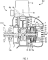
FIG. 1 is a partial cross-sectional view schematically showing an outline configuration of an engine unit EU according to an embodiment of the present teaching. The engine unit EU of this embodiment is a four-stroke engine unit for use in vehicle. - The engine unit EU is a unit mounted to a straddled vehicle 1 (see
FIG. 13 ), for example. The engine unit EU includes a four-stroke engine body 10 and astarter motor 20. The four-stroke engine body 10 is a single-cylinder four-stroke engine including one cylinder. Hereinafter, the four-stroke engine body is simply referred to as an engine body. In theengine body 10, the relationship shown inFIG. 2 is established between a crank angle position and a required torque. The required torque means a torque required for rotating acrankshaft 15. -
FIG. 2 is an illustrative diagram schematically showing the relationship between the crank angle position and the required torque at a time of engine start. The relationship between the crank angle position and the required torque shown inFIG. 2 is under a state where combustion is stopped. - The
engine body 10 has, during four strokes, a high-load region TH in which a high load is put on rotation of thecrankshaft 15 and a low-load region TL in which a load put on rotation of thecrankshaft 15 is lower than that of the high-load region TH. The high-load region means a region in one combustion cycle of theengine body 10 where a load torque is higher than an average value Av of the load torque over the one combustion cycle. From the viewpoint of the rotation angle of thecrankshaft 15, the low-load region TL is equal to or wider than the high-load region TH. To be specific, the low-load region TL is wider than the high-load region TH. In other words, a rotation angle region corresponding to the low-load region TL is wider than a rotation angle region corresponding to the high-load region TH. During rotation, theengine body 10 repeats four strokes, namely, an intake stroke, a compression stroke, an expansion stroke, and an exhaust stroke. The compression stroke overlaps the high-load region TH. - One combustion cycle of the
engine body 10 includes one intake stroke, one compression stroke, one expansion stroke, and one exhaust stroke. - As shown in
FIG. 1 , the engine unit EU includes thestarter motor 20. Thestarter motor 20 is a three-phase brushless motor. At a time of engine start, thestarter motor 20 starts theengine body 10 by driving thecrankshaft 15 in forward rotation. - The
starter motor 20 is attached to thecrankshaft 15 of theengine body 10. In this embodiment, thestarter motor 20 is attached to thecrankshaft 15 without interposition of a power transmission mechanism (such as a belt, a chain, a gear, a speed reducer, or a speed increaser). In the present teaching, thestarter motor 20 is configured such that forward rotation of thestarter motor 20 causes forward rotation of thecrankshaft 15. In the present teaching, it is preferable that the rotation axis line of thestarter motor 20 is substantially coincident with the rotation axis line of thecrankshaft 15. It is also preferable that thestarter motor 20 is attached to thecrankshaft 15 without interposition of any power transmission mechanism, as illustrated in this embodiment. - The
engine body 10 includes a crankcase 11, acylinder 12, apiston 13, a connectingrod 14, and thecrankshaft 15. Thepiston 13 is arranged in thecylinder 12 such that thepiston 13 is freely movable to and fro. - The
crankshaft 15 is rotatably arranged in thecrank case 11. The connectingrod 14 connects thepiston 13 and thecrankshaft 15 to each other. Acylinder head 16 is attached to an upper portion of thecylinder 12. Thecylinder 12, thecylinder head 16, and thepiston 13 define a combustion chamber. Thecrankshaft 15 is supported on thecrank case 11 via a pair ofbearings 17 in a freely rotatable manner. Thestarter motor 20 is attached to oneend portion 15a of thecrankshaft 15. A transmission CVT is attached to theother end portion 15b of thecrankshaft 15. The transmission CVT changes the gear ratio which is the ratio of an output rotation speed to an input rotation speed. - The engine unit EU is provided with a throttle valve SV and a
fuel injector device 18. The throttle valve SV adjusts the amount of air to be supplied to the combustion chamber. The degree of opening of the throttle valve SV is adjusted in accordance with an operation on an acceleration operator, for example. Thefuel injector device 18 injects a fuel, to supply the fuel to the combustion chamber. Theengine body 10 has aspark plug 19. - The
engine body 10 outputs rotational power through thecrankshaft 15. The rotational power of thecrankshaft 15 is transmitted to awheel 3b (seeFIG. 13 ) via the transmission CVT. The straddled vehicle 1 (seeFIG. 13 ) is driven by thewheel 3b that receives the rotational power outputted from theengine body 10 through thecrankshaft 15. -
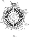
FIG. 3 is a cross-sectional view of thestarter motor 20 shown inFIG. 1 , as sectioned perpendicular to its rotation axis line. Thestarter motor 20 is described with reference toFIGS. 1 and3 . - The
starter motor 20 is a three-phase brushless motor of permanent magnet type. Thestarter motor 20 of this embodiment is a motor of radial gap type. Thestarter motor 20 is a motor of outer rotor type. - The
starter motor 20 includes arotor 30 and astator 40. Therotor 30 is an outer rotor. Thestator 40 is an inner stator. Therotor 30 includes arotor body part 31. Therotor body part 31 is made of, for example, a ferromagnetic material. Therotor body part 31 is in the shape of a cylinder with a bottom. Therotor body part 31 includes acylindrical boss portion 32, a disk-shapedbottom wall portion 33, and aback yoke portion 34 having a cylindrical shape. Thebottom wall portion 33 and theback yoke portion 34 are integrally formed. Here, it may also be acceptable that thebottom wall portion 33 and theback yoke portion 34 are formed as separate parts. Thebottom wall portion 33 and theback yoke portion 34 are secured to thecrankshaft 15 via thecylindrical boss portion 32. A winding to which a current is supplied is not provided in therotor 30. - The
rotor 30 includes apermanent magnet part 37. Therotor 30 includes a plurality ofmagnetic pole portions 37a. The plurality ofmagnetic pole portions 37a are formed by thepermanent magnet part 37. The plurality ofmagnetic pole portions 37a are provided on an inner circumferential surface of theback yoke portion 34. In this embodiment, thepermanent magnet part 37 includes a plurality of permanent magnets. The plurality ofmagnetic pole portions 37a are provided in the plurality of permanent magnets, respectively. - The
permanent magnet part 37 may alternatively be configured as a single annular permanent magnet. In such a configuration, the single permanent magnet is magnetized such that the plurality ofmagnetic pole portions 37a appear side by side on the inner circumferential surface. - The plurality of
magnetic pole portions 37a are provided such that N pole and S pole appear alternately with respect to the circumferential direction of thestarter motor 20. In this embodiment, the number of magnetic poles of therotor 30 opposed to thestator 40 is twenty-four. The number of magnetic poles of therotor 30 means the number of magnetic poles opposed to thestator 40. No magnetic material is arranged between themagnetic pole portions 37a and thestator 40. The permanent magnets of therotor 30 are opposed to thestator 40 with only an air gap therebetween. Themagnetic pole portions 37a are provided outside thestator 40 with respect to the radial direction of thestarter motor 20. Theback yoke portion 34 is provided outside themagnetic pole portions 37a with respect to the radial direction. The number ofmagnetic pole portions 37a included in thestarter motor 20 is more than the number ofteeth 43. - A cooling fan F is provided to the
bottom wall portion 33 of therotor 30. - The
stator 40 includes a stator core ST and a plurality of stator windings W. The stator core ST includes a plurality ofteeth 43 arranged at intervals with respect to the circumferential direction. The plurality ofteeth 43 integrally extend from the stator core ST toward radially outside. In this embodiment, eighteenteeth 43 in total are arranged at intervals with respect to the circumferential direction. In other words, the stator core ST has eighteen slots SL in total that are arranged at intervals with respect to the circumferential direction. Theteeth 43 are arranged at equal intervals with respect to the circumferential direction. - The number of
magnetic pole portions 37a included in therotor 30 is more than the number ofteeth 43. The number ofmagnetic pole portions 37a is equal to 4/3 of the number of slots. - The stator winding W is wound around each of the
teeth 43. That is, the multi-phase stator windings W are arranged through the slots SL. In the state shown inFIG. 3 , the stator windings W are in the slots SL. Each of the multi-phase stator windings W belongs to any of U-phase, V-phase, and W-phase. The stator windings W are arranged in the order of V-phase, U-phase, and W-phase, for example. A manner in which the stator winding W is wound may be, though not particularly limited, either concentrated winding or distributed winding, and it preferably is concentrated winding. - The
starter motor 20 is connected to thecrankshaft 15 of theengine body 10. Therotor 30 is connected to thecrankshaft 15 such that therotor 30 is rotated along with rotation of thecrankshaft 15. More specifically, therotor 30 is connected to thecrankshaft 15 such that therotor 30 is rotated with its speed ratio fixed relative to thecrankshaft 15. - In this embodiment, the
rotor 30 is attached to thecrankshaft 15 without interposition of a power transmission mechanism (such as a belt, a chain, a gear, a speed reducer, or a speed increaser). Therotor 30 is rotated with a speed ratio of 1:1 relative to thecrankshaft 15. Thestarter motor 20 is configured such that therotor 30 is driven in forward rotation at a time of combustion operation of theengine body 10. - At a time of engine start, the
starter motor 20 drives thecrankshaft 15 in forward rotation to start theengine body 10. - The
rotor 30 is described in more detail. Thepermanent magnet part 37 is provided outside thestator 40 with respect to the radial direction of thestarter motor 20. Theback yoke portion 34 is provided outside thepermanent magnet part 37 with respect to the radial direction. Thepermanent magnet part 37 includes, on its surface facing thestator 40, a plurality of magnetic pole faces 37a. The magnetic pole faces 37a are arranged side by side in the circumferential direction of thestarter motor 20. Each of the magnetic pole faces 37a has N pole or S pole. N pole and S pole are arranged alternately with respect to the circumferential direction of thestarter motor 20. The magnetic pole faces 37a of thepermanent magnet part 37 face thestator 40. In this embodiment, a plurality of magnets are arranged in the circumferential direction of thestarter motor 20, and each of the plurality of magnets is disposed with its S pole and N pole lining up in the radial direction of thestarter motor 20. One S pole and one N pole adjacent to each other with respect to the circumferential direction constitute a magneticpole face pair 37p. The number of magneticpole face pairs 37p is 1/2 of the number of magnetic pole faces 37a. In this embodiment, therotor 30 includes twenty-four magnetic pole faces 37a which are opposed to thestator 40. The number of magneticpole face pairs 37p included in therotor 30 is twelve. In the figure, twelve magnetic pole face pairs 37p corresponding to twelve magnet pairs are shown. For clarity of the figure, however, only onepair 37p is given the reference sign. The number of magnetic pole faces 37a included in thestarter motor 20 is more than 2/3 of the number ofteeth 43. The number of magnetic pole faces 37a included in thestarter motor 20 is equal to or more than 4/3 of the number ofteeth 43. - The
rotor 30 includes, on its outer surface, a plurality ofdetection object parts 38 for detection of the rotation position of therotor 30. Magnetic effects are used to detect the plurality ofdetection object parts 38. The plurality ofdetection object parts 38 arranged at intervals with respect to the circumferential direction are provided on the outer surface of therotor 30. In this embodiment, the plurality ofdetection object parts 38 are provided on an outer circumferential surface of therotor 30 at intervals with respect to the circumferential direction. The plurality ofdetection object parts 38 are arranged on an outer circumferential surface of theback yoke portion 34 having a cylindrical shape. Each of the plurality ofdetection object parts 38 protrudes from the outer circumferential surface of theback yoke portion 34, outward with respect to the radial direction Y of thestarter motor 20. The widths of the plurality ofdetection object parts 38 are equal with respect to the circumferential direction. Each of the plurality ofdetection object parts 38 has a shape extending from itsforward end 38a to itsrearward end 38b with respect to the circumferential direction. Thebottom wall portion 33, theback yoke portion 34, and thedetection object parts 38 are integrally formed by, for example, stamping a metal plate such as an iron plate. Thus, thedetection object parts 38 are made of a ferromagnetic material. A detailed description of how thedetection object parts 38 are arranged is given later. - The engine unit EU is provided with a rotor
position detection device 50. The rotorposition detection device 50 is a device that detects the position of therotor 30. The rotorposition detection device 50 is provided at a position allowed to be opposed to the plurality ofdetection object parts 38. The rotorposition detection device 50 is not simultaneously opposed to the plurality ofdetection object parts 38, but is opposed to one after another of the plurality ofdetection object parts 38. That is, the rotorposition detection device 50 is arranged at such a position that the plurality ofdetection object parts 38 sequentially comes into opposition against the rotorposition detection device 50. The rotorposition detection device 50 is opposed to a path through which thedetection object parts 38 pass along with rotation of therotor 30. The rotorposition detection device 50 is arranged at a position distant from thestator 40. In this embodiment, the rotorposition detection device 50 is arranged such that theback yoke portion 34 and thepermanent magnet part 37 of therotor 30 are located between the rotorposition detection device 50 and thestator 40 with the stator windings W with respect to the radial direction of thecrankshaft 15. The rotorposition detection device 50, which is arranged outside therotor 30 with respect to the radial direction of thestarter motor 20, is oriented to the outer circumferential surface of therotor 30. - The rotor
position detection device 50 includes a detection-purpose winding 51. The detection-purpose winding 51 is a winding provided independently of the stator windings W of thestator 40. The stator windings Ware supplied with a current for driving therotor 30 of thestarter motor 20 by an electromagnetic force, whereas the detection-purpose winding 51 is not supplied with the current for driving therotor 30 of thestarter motor 20. The stator windings W produce magnetic fluxes for driving therotor 30, whereas the detection-purpose winding 51 does not produce any magnetic flux for driving therotor 30. The rotorposition detection device 50 has a higher heat resistance than a Hall IC or an MR sensor which uses a semiconductor device to detect the position. This can eliminate the need to provide a special heat shield structure for protecting the semiconductor device from engine heat. - An electrical signal flowing in the detection-purpose winding 51 varies as a magnetic state changes due to movement of the plurality of
detection object parts 38 along with rotation of thecrankshaft 15. The rotorposition detection device 50 also includes a detection-purpose magnet 52 and acore 53. Thecore 53 is an elongated rod-like member made of, for example, iron. The detection-purpose winding 51 is wound on thecore 53. The detection-purpose magnet 52 is provided at one end of thecore 53. Thecore 53 has, at the other end thereof, adetection end face 53a. Thedetection end face 53a, during rotation of therotor 30, comes into opposition against each of the plurality ofdetection object parts 38 with an air gap therebetween. The detection-purpose winding 51 functions as a pick-up coil that detects thedetection object parts 38. - As the
rotor 30 rotates, thedetection object parts 38 provided on the outer circumferential surface of theback yoke portion 34 come close to or away from thecore 53, and at that time, a magnetic flux linked with the detection-purpose winding 51 is changed. In accordance with this change, a voltage generated by an electromotive force occurring in the detection-purpose winding 51 varies. As a result, an electrical signal according to the detection-purpose winding 51 flows in the detection-purpose winding 51. - With this mechanism, the detection-purpose winding 51 magnetically detects the
detection object parts 38. The detection-purpose winding 51 detects thedetection object parts 38 afterrotor 30 starts rotation. In other words, the rotorposition detection device 50 starts to detect the rotation position of therotor 30, after thecrankshaft 15 starts rotation. During rotation of therotor 30, the rotorposition detection device 50 magnetically detects thedetection object parts 38 one after another by the detection-purpose winding 51. More specifically, the rotorposition detection device 50 detects the opposite ends of eachdetection object part 38 with respect to the circumferential direction, that is, theforward end 38a and therearward end 38b. The detection-purpose winding 51 of the rotorposition detection device 50 outputs an electrical signal to a control device CT (seeFIG. 5 ). - Here, referring to
FIG. 3 , a description is given of arrangement of thedetection object parts 38 of therotor 30. In this embodiment, the plurality ofdetection object parts 38 are provided on the outer surface of therotor 30, and the positions of the plurality ofdetection object parts 38 have substantially the same positional relationship relative to the corresponding magnetic pole face pairs 37p, respectively. Thus, the forward ends 38a of the plurality ofdetection object parts 38 are arranged at positions having substantially the same positional relationship relative to the corresponding magnetic pole face pairs 37p, respectively, and the rearward ends 38b of the plurality ofdetection object parts 38 are arranged at positions having substantially the same positional relationship relative to the corresponding magnetic pole face pairs 37p, respectively. Here, the position of theforward end 38a and the position of therearward end 38b have different positional relationships relative to the corresponding magneticpole face pair 37p. - In
FIG. 3 , the dashed and dotted lines indicate specified positions with respect to the circumferential direction, which are defined in advance. Each of the specified positions is a position in the magneticpole face pair 37p including two magnetic poles (S pole and N pole) adjacent to each other with respect to the circumferential direction. The specified positions are substantially identical in terms of their locations in corresponding ones of the plurality of magnetic pole facespairs 37p. The specified positions represent substantially the same electrical angle phase in corresponding ones of the magnetic pole face pairs 37p. The electrical angle is a rotation angle based on a cycle of repetition of the magneticpole face pair 37p. The entirety of the magneticpole face pair 37p corresponds to 360 degrees in electrical angle. Each of the plurality ofdetection object parts 38 is arranged at the specified position in each of the magnetic pole face pairs 37p. Since the plurality ofdetection object parts 38 have substantially the same positional relationship relative to the magnetic pole face pairs 37p, correlating a variation in the electrical signal in the detection-purpose winding 51 with the electrical angle of thestarter motor 20 is easy. To be specific, both an electrical signal variation corresponding to theforward end 38a of thedetection object part 38 and an electrical signal variation corresponding to therearward end 38b thereof can be easily correlated with the electrical angle of thestarter motor 20. As the specified position where the plurality ofdetection object parts 38 are arranged, positions other than the positions shown inFIG. 3 , that is, positions offset from the positions indicated by the dashed and dotted lines inFIG. 3 , can be employed as long as such positions have substantially the same positional relationship relative to the corresponding magnetic pole face pairs 37p of the plurality ofdetection object parts 38. As shown inFIG. 3 , not all of the plurality ofdetection object parts 38 are arranged at equal intervals. There are positions (specified positions) located at equal intervals, and a position (blank position) having nodetection object part 38 arranged therein. - In this embodiment, the plurality of
detection object parts 38 provided on the outer surface of therotor 30 are at angular intervals of [360 degrees / (a positive divisor of the number of magnetic pole face pairs, the positive divisor greater than one)] with respect to the circumferential direction. The 360 degrees represent the mechanical angle. The rotorposition detection device 50 is provided at a position allowed to be opposed to each of the plurality ofdetection object parts 38 during rotation of therotor 30. The plurality ofdetection object parts 38 provided on the outer surface of therotor 30 are at angular intervals of [360 degrees / (the positive divisor of the number of magnetic pole face pairs, the positive divisor greater than one)] with respect to the circumferential direction. In the example shown inFIG. 3 , the number equal to the number of magnetic pole face pairs is selected as (the positive divisor of the number of magnetic pole face pairs, the positive divisor greater than one). Thus, more specifically, the plurality ofdetection object parts 38 provided on the outer surface of therotor 30 are at angular intervals of [360 degrees / (the number of magnetic pole face pairs)] with respect to the circumferential direction. In the example shown inFIG. 3 , the number of magnetic pole face pairs is twelve. The plurality ofdetection object parts 38 provided on therotor 30 are at angular intervals of [360 degrees / 12]. The plurality ofdetection object parts 38 provided on the outer surface of therotor 30 are at angular intervals of 30 degrees. - The specified positions indicated by the dashed and dotted lines in
FIG. 3 represent angular intervals of 30 degrees. Since the plurality ofdetection object parts 38 are provided at angular intervals of [360 degrees / (the positive divisor of the number of magnetic pole face pairs, the positive divisor greater than one)] with respect to the circumferential direction, correlating a variation in the electrical signal in the detection-purpose winding 51 with the electrical angle of thestarter motor 20 is easy. - In this embodiment, the
rotor 30 is provided with elevendetection object parts 38, the number of which is one less than the number of the specified positions. The elevendetection object parts 38 are arranged at eleven of the twelve specified positions, respectively. That is, the plurality ofdetection object parts 38 provided on the outer surface of therotor 30 are arranged at positions that are spaced by a plurality of substantially equal intervals and one interval different from the plurality of substantially equal intervals. The one interval different from the plurality of substantially equal intervals is wider than each of the plurality of intervals. The rotorposition detection device 50 is provided at a position allowed to be opposed to the plurality ofdetection object parts 38 during rotation of therotor 30. The plurality ofdetection object parts 38 are spaced by the plurality of equal intervals and the one different interval. In the example shown inFIG. 3 , the elevendetection object parts 38 are arranged at positions that are spaced by a plurality of intervals of 30 degrees and one interval of 60 degrees which is different from the plurality of intervals of 30 degrees. That is, the plurality of (twelve) specified positions on the outer surface of therotor 30 are at equal intervals or at substantially equal intervals with respect to the circumferential direction of thecrankshaft 15. The angular interval between twodetection object parts 38 that are arranged at, among the plurality of specified positions, the two specified positions each adjacent to the position (blank position) having nodetection object part 38 arranged therein with respect to the circumferential direction is twice the angular interval between any of the other detection objectparts 38. Since one of the intervals of the plurality ofdetection object parts 38 is different from the others, a reference position in one rotation of thecrankshaft 15 can be detected. -
FIGS. 4(A) and 4(B) show a part of the rotorposition detection device 50 and a part of therotor 30 on an enlarged scale.FIG. 4(A) shows a state where thedetection object part 38 and thedetection end face 53a start to overlap in the circumferential direction.FIG. 4(B) shows a state where the overlap between thedetection object part 38 and thedetection end face 53a in the circumferential direction terminates. -
FIG. 4(A) shows theback yoke portion 34 and thedetection object parts 38 of therotor 30. Each of thedetection object parts 38 has theforward end 38a and therearward end 38b. Theforward end 38a and therearward end 38b are ends of thedetection object part 38 with respect to the circumferential direction. Theforward end 38a is located forward with respect to a direction in which thedetection object parts 38 move along with rotation of therotor 30. Therearward end 38b is located rearward with respect to the direction in which thedetection object parts 38 move. - As shown in
FIG. 4(A) , twodetection object parts 38 adjacent to each other have aninterval 34a therebetween. - With respect to the circumferential direction, a width W2 of the
detection object part 38 and a width W1 of theinterval 34a between thedetection object parts 38 satisfy the following relationship:
- More specifically, the width W2 of the
detection object part 38 and the width W1 of theinterval 34a between thedetection object parts 38 substantially satisfy the following relationship:
- In the situation shown in
FIG. 4(A) , theforward end 38a of thedetection object part 38 overlaps oneend 53d of thedetection end face 53a with respect to the circumferential direction. In the situation shown inFIG. 4(B) , on the other hand, therearward end 38b of thedetection object part 38 overlaps theother end 53e of thedetection end face 53a with respect to the circumferential direction. - The rotor
position detection device 50 uses, for detection, a change in the magnetic flux linked with the detection-purpose winding 51 wound on thecore 53. The magnetic flux changes in accordance with a change in the magnetic resistance of a magnetic path including thecore 53. A change in the magnetic resistance of the magnetic path depends mainly on the shortest distance between the core 53 and thedetection object part 38. The shortest distance between the core 53 and thedetection object part 38 exhibits the greatest change in the situation shown inFIG. 4(A) and the situation shown inFIG. 4(B) . In the situation shown inFIG. 4(A) and the situation shown inFIG. 4(B) , the magnetic flux linked with the detection-purpose winding 51 exhibits the maximum change. - As shown in
FIG. 4(A) , at a time when thedetection object part 38 and thedetection end face 53a start to overlap in the circumferential direction, the electrical signal in the detection-purpose winding 51 varies in accordance with theforward end 38a of the detection object part 38 (see a signal D1 at time t1 inFIG. 6 ). As shown inFIG. 4(B) , at a time when the overlap between thedetection object part 38 and thedetection end face 53a in the circumferential direction terminates, the electrical signal in the detection-purpose winding 51 varies in accordance with therearward end 38b of the detection object part 38 (see the signal D1 at time t2 inFIG. 6 ). In the situation shown inFIG. 4(A) , theforward end 38a of thedetection object part 38 is detected. In the situation shown inFIG. 4(B) , therearward end 38b of thedetection object part 38 is detected. - When considered based on the rotation angle of the
rotor 30, a position where the electrical signal flowing in the detection-purpose winding 51 varies in accordance with therearward end 38b of thedetection object part 38 is approximated to the midpoint between the variations corresponding to two forward ends 38a adjacent to each other with therearward end 38b interposed therebetween. For example, when therotor 30 is rotated at a constant speed, the electrical signal flowing in the detection-purpose winding 51 has a small difference between the time interval from a signal variation corresponding to theforward end 38a to a signal variation corresponding to therearward end 38b and the time interval from a signal variation corresponding to therearward end 38b to a signal variation corresponding to theforward end 38a. - In more detail, the time interval from a signal variation corresponding to the
forward end 38a to a signal variation corresponding to therearward end 38b is substantially equal to the time interval from a signal variation corresponding to therearward end 38b to a signal variation corresponding to theforward end 38a. In other words, the ratio between the time interval from a signal variation corresponding to theforward end 38a to a signal variation corresponding to therearward end 38b and the time interval from a signal variation corresponding to therearward end 38b to a signal variation corresponding to theforward end 38a is substantially 50:50. The time interval between a signal variation corresponding to theforward end 38a and a signal variation corresponding to therearward end 38b is equalized. Detection of desynchronization or correction of the phase of a current variation, which will be described later, is performed based on a timing when the equalized time interval changes. This enables detection of desynchronization or correction of the phase of a current variation to be performed with an further high accuracy. As a result, early-start ability of the engine is further improved. -
FIG. 5 is a block diagram showing a basic electrical configuration of the engine unit EU shown inFIG. 1 . - The engine unit EU includes the
engine body 10, thestarter motor 20, the rotorposition detection device 50, aninverter 61, and the control device CT. Thespark plug 19 and abattery 4 are connected to the control device CT. - The engine unit EU includes the rotor
position detection device 50 and theinverter 61. - The
inverter 61 includes a plurality of switchingparts 611 to 616. Theinverter 61 includes six switchingparts 611 to 616. The switchingparts 611 to 616 constitute a three-phase bridge inverter. The plurality of switchingparts 611 to 616, which are connected to the respective phases of the multi-phase stator windings W, selectively allow or block the passing of a current between the multi-phase stator windings W and thebattery 4. More specifically, when thestarter motor 20 functions as a starter motor, a current flowing in each of the multi-phase stator windings W is controlled based on on/off-operation of the switchingparts 611 to 616. - Each of the switching
parts 611 to 616 has a switching element. The switching element is, for example, a transistor and in more detail, an FET (Field Effect Transistor). - The control device CT includes a
starter control unit 62, acombustion control unit 63, and a bothedge detection unit 66. - The
starter control unit 62 controls on/off-operation of each of the switchingparts 611 to 616, to control the operation of thestarter motor 20. - The
starter control unit 62 includes astart control unit 621, anacceleration control unit 622, an on/off-operation storage unit 623, and aninitial operation unit 624. Thecombustion control unit 63 and thestarter control unit 62 including thestart control unit 621 and theacceleration control unit 622 are implemented by a computer (not shown) and control software executable by the computer. Thus, below-described operations performed respectively by thecombustion control unit 63 and thestarter control unit 62 including thestart control unit 621, theacceleration control unit 622, the on/off-operation storage unit 623, and theinitial operation unit 624 can be considered as operations performed by the control device CT. - The
combustion control unit 63 and thestarter control unit 62 including thestart control unit 621 and theacceleration control unit 622 may be partially or entirely implemented by a wired logic which is an electronic circuit. Thestarter control unit 62 and thecombustion control unit 63 may be, for example, either configured as separate devices placed at a distance from each other, or integrated as a single device. - The on/off-
operation storage unit 623 is formed of, for example, a memory. The on/off-operation storage unit 623 stores data relating to on/off-operation of the plurality of switchingparts 611 to 616. To be more specific, the on/off-operation storage unit 623 stores a map of information used when the control device CT controls thestarter motor 20 and theengine body 10, and software containing the information. Theinitial operation unit 624 is formed of an electronic circuit. Theinitial operation unit 624 generates an electrical signal for performing on/off-operation of the plurality of switchingparts 611 to 616 when thecrankshaft 15 is in a stopped state. The control device CT may concurrently operate both the on/off-operation storage unit 623 and theinitial operation unit 624, or may operate one of the on/off-operation storage unit 623 and theinitial operation unit 624. - The
combustion control unit 63 controls injection of thefuel injector device 18, to control the combustion operation of theengine body 10. Thecombustion control unit 63 directs thespark plug 19 to perform an ignition operation, to control the combustion operation of theengine body 10. - A
starter switch 6 for starting theengine body 10 is connected to thestarter control unit 62. Thestarter switch 6 is actuated by the rider at a time of starting theengine body 10. - The both
edge detection unit 66 detects variations in the electrical signal flowing in the detection-purpose winding 51 of the rotorposition detection device 50, the variations corresponding to both theforward end 38a and therearward end 38b of thedetection object part 38. The bothedge detection unit 66 is, for example, a waveform shaping circuit connected to the detection-purpose winding 51. The bothedge detection unit 66 includes, for example, a circuit for differentiating the electrical signal flowing in the detection-purpose winding 51 and a circuit for limiting the amplitude thereof. -
FIG. 6 shows graphs of an electrical signal flowing in the detection-purpose winding 51 and an output signal of the bothedge detection unit 66. The horizontal axis of the graphs represents time elapse. - In
FIG. 6 , the solid line D1 indicates an electrical signal flowing in the detection-purpose winding 51 while therotor 30 is rotating. At time t1, an electrical signal D1 flowing in the detection-purpose winding 51 exhibits a negative value. The negative value means a variation corresponding to theforward end 38a of the detection object part 38 (seeFIG. 4 ). At time t2, the electrical signal D1 flowing in the detection-purpose winding 51 exhibits a positive value. The positive value means a variation corresponding to therearward end 38b of the detection object part 38 (seeFIG. 4 ). - The both
edge detection unit 66 converts the electrical signal D1 into a binary output signal D2 which is easily identifiable by thestarter control unit 62 and thecombustion control unit 63. The bothedge detection unit 66 outputs the output signal D2 corresponding to the electrical signal D1 flowing in the detection-purpose winding 51. The bothedge detection unit 66 outputs a rising edge signal as a signal representing a variation corresponding to theforward end 38a of thedetection object part 38. The bothedge detection unit 66 outputs a falling edge signal as a signal representing a variation corresponding to therearward end 38b of thedetection object part 38. As a result of signal processing performed by the bothedge detection unit 66, a gap is caused between a peak timing of the electrical signal D1 flowing in the detection-purpose winding 51 and an edge timing of the output signal D2. It, however, is easy to perform the processing in consideration of the gap, because the gap between the timings occurs in the same direction. Thus, the rising edge signal of the output signal D2 is treated substantially as a signal representing a variation corresponding to theforward end 38a of thedetection object part 38. The falling edge signal of the output signal D2 is treated substantially as a signal representing a variation corresponding to therearward end 38b of thedetection object part 38. - The
starter control unit 62 and thecombustion control unit 63 control on/off-operation of the switchingparts 611 to 616, based on the variation corresponding to theforward end 38a of thedetection object part 38 and the variation corresponding to therearward end 38b of thedetection object part 38, the variations included in the electrical signal D1 flowing in the detection-purpose winding 51. Thestarter control unit 62 and thecombustion control unit 63, actually, control on/off-operation of the switchingparts 611 to 616, based on the rising edge corresponding to theforward end 38a of thedetection object part 38 and the falling edge corresponding to therearward end 38b of thedetection object part 38, the rising and falling edges included in the output signal D2 of the bothedge detection unit 66. -
FIGS. 7 and8 are flowcharts illustrating operations of the engine unit EU shown inFIG. 5 . The engine unit EU is controlled by the control device CT.FIG. 7 mainly shows a control in a start control mode.FIG. 8 shows a control following the control shown inFIG. 7 .FIG. 8 mainly shows a control in an acceleration control mode. - First, an outline of the operation is described.
- In response to reception of a start instruction under a state where rotation of the
crankshaft 15 is stopped (S11), the control device CT directs thestarter motor 20 to drive thecrankshaft 15 in forward rotation. The control device CT thus starts theengine body 10. - In starting the
engine body 10, the control device CT shifts from the start control mode (S12 to S19) in which forward rotation of thecrankshaft 15 is started to the acceleration control mode (S31 to S43) in which forward rotation of thecrankshaft 15 is accelerated. More specifically, the start control unit 621 (FIG. 5 ) executes rotation start processing (S12 to S19), and then theacceleration control unit 622 executes acceleration control processing (S31 to S43). - An operation in the start control mode is described with reference to
FIG. 7 . - When the start instruction is received (S11), the control device CT sets a speed initial value as a speed target value (S12). The speed initial value is a target value at a time point of starting rotation of the
crankshaft 15. The speed target value is, for example, set to be "0" as the speed initial value. - Then, the control device CT controls ramp driving (S13). To be exact, the
start control unit 621 of thestarter control unit 62 controls the ramp driving. - In the ramp driving (S13), the control device CT performs on/off-operation of the plurality of switching
parts 611 to 616 at predefined timings in the state where thecrankshaft 15 is stopped. To be exact, thestart control unit 621 performs on/off-operation of the plurality of switchingparts 611 to 616 at predefined timings in the state where thecrankshaft 15 is stopped. In this manner, the control device CT supplies a current to the multi-phase stator windings W, to start forward rotation of thecrankshaft 15. - In the ramp driving (S13), the control device CT performs on/off-operation of the switching
parts 611 to 616 based on an open-loop control. In other words, the control device CT sequentially renders the multi-phase stator windings W conducting at predefined timings, without performing a feedback control based on the position of therotor 30. The control device CT does not bring the conduction of the stator windings W into synchronization with the position of therotor 30. - The control device CT of this embodiment performs sine wave drive of the stator windings W. In the sine wave drive, the control device CT performs on/off-operation of the plurality of switching
parts 611 to 616 such that a sinusoidal current flows in each stator winding W of thestarter motor 20. The control device CT causes the sinusoidal current to flow in the stator windings W by dynamically changing the duty cycle of the switchingparts 611 to 616 corresponding to the respective stator windings W. The control device CT causes the sinusoidal current to flow in the stator windings W by performing on/off-operation of the switchingparts 611 to 616 with a cycle shorter than one cycle in electrical angle. - In detail, the control device CT includes an electrical angle counter indicating the electrical angle. The electrical angle represents the position of the
rotor 30 based on the magneticpole face pair 37p. The electrical angle is the rotation angle based on the cycle of repetition of the magneticpole face pair 37p. The entirety of the magneticpole face pair 37p corresponds to 360 degrees in electrical angle. - In the ramp driving (S13) in the start control mode, the control device CT increases an electrical angle counter value. For example, the control device CT repeatedly increases the electrical angle counter value from 0 to 360. The electrical angle counter value increases in the shape of a ramp.
- In more detail, the control device CT increases the electrical angle counter value into a value corresponding to the speed target value. As the speed target value, the initial value is set in step S12 mentioned above. The control device CT increases the speed target value as time elapses. In the ramp driving (S13) in the start control mode, the speed target value does not reflect the actual rotation speed of the
rotor 30. In the start control mode, the speed target value increases as time elapses, irrespective of the actual rotation speed of therotor 30. In the start control mode, the speed target value is a target value of the rotation speed of therotor 30. - As the electrical angle counter value increases into a value corresponding to the speed target value, the increment speed of the electrical angle counter also increases. Performing on/off-operation of the switching
parts 611 to 616 with a duty cycle corresponding to the electrical angle counter value causes the current flowing in the stator windings W to vary. The cycle of variation is gradually shortened over time. - More specifically, the control device CT performs on/off-operation of the switching
parts 611 to 616 in a duty cycle pattern corresponding to the electrical angle counter value. The pattern is, for example, a pattern in which paths of currents flowing in the stator windings W of U-phase, V-phase, and W-phase are sequentially switched. The control device CT performs on/off-operation of the switchingparts 611 to 616 such that a sinusoidal current flows in the stator windings W, for example. -
FIG. 9 contains graphs illustrating an exemplary relationship between the electrical angle and the duty of the switchingparts 611 to 616. -
FIG. 9 shows the correspondence relationship among the electrical angle AGL, an on/off-operation pattern Vsup of the V-phase switching part for example, and the current flowing in the stator windings W. On/off of the switching part represents the duty cycle. For example, the electrical angle AGL and the on/off-operation pattern are stored in association with the on/off-operation storage unit 623. The on/off-operation storage unit 623 stores such a duty cycle pattern that a sinusoidal voltage is generated in accordance with an increase in the electrical angle AGL. - The control device CT refers to the on/off-
operation storage unit 623, to perform on/off-operation of the switching part with the duty corresponding to the electrical angle AGL. The on/off duty cycle of the switching part dynamically changes in accordance with an increase in the electrical angle (electrical angle counter value). - The control device CT causes a sinusoidal current to flow in the stator windings W by performing on/off-operation of the switching
parts 611 to 616 with a cycle shorter than one cycle (360 degrees) in electrical angle. - The on/off-
operation storage unit 623 stores U-phase and W-phase patterns in addition to the V-phase pattern. - This is how the control device CT supplies a current to the multi-phase stator windings W by performing on/off-operation of the plurality of switching
parts 611 to 616 at predefined timings based on the data stored in the on/off-operation storage unit 623. - Causing the sinusoidal current to flow in the stator windings W enables efficient conversion of power into rotational power. As a result, the torque outputted from the
starter motor 20 increases. - It may be possible that the control device CT performs on/off-operation of the switching
parts 611 to 616 at predefined timings without reading out the data from the on/off-operation storage unit 623. For example, information about time and states of the plurality of switching parts may be included in the program of the control device CT. It may be possible that the control device performs on/off-operation of the plurality of switching parts at predefined timings by calculating a mathematical expression indicating a timing. It may be possible that the control device performs on/off-operation of the plurality of switching parts at predefined timings by using an electronic circuit (wired logic). For example, theinitial operation unit 624 is an electronic circuit for generating a timing signal for performing on/off-operation of the switchingparts 611 to 616. Theinitial operation unit 624 outputs a signal at a timing with its cycle shortened over time. Theinitial operation unit 624 may output a signal for performing on/off-operation of the plurality of switchingparts 611 to 616. In other words, the control device CT may perform on/off-operation of the switchingparts 611 to 616 at predefined timings based on the signal outputted from theinitial operation unit 624. - In the ramp driving (S13) in the start control mode, the on/off state of the switching
parts 611 to 616 and the on/off duty cycle are dynamically changed. The electrical angle (electrical angle counter value) based on which on/off-operation is performed, however, does not reflect actual rotation of therotor 30. The on/off-operation timings of the switchingparts 611 to 616 are defined irrespective of the position information of therotor 30. Thus, the switchingparts 611 to 616 are operated at predefined timings. -
FIG. 10(A) is a graph schematically showing a variation in the current flowing in the stator windings W.FIGS. 10(B) to 10(E) show positional relationships between therotor 30 and thestator 40.FIG. 10(B) shows a first positional relationship.FIG. 10(C) shows a second positional relationship.FIG. 10(D) shows a third positional relationship.FIG. 10(E) shows a fourth positional relationship. - The horizontal axis in
FIGS. 10(B) to 10(E) represents the electrical angle. It should be noted that the horizontal axis shows a range of 180 to 360 degrees in electrical angle. The horizontal axis inFIGS. 10(B) to 10(E) also represents the phase of the current flowing in the stator windings W. The horizontal axis inFIGS. 10(B) to 10(E) also represents time in a state where therotor 30 is rotated at a constant speed. -
FIG. 10(A) also shows a forward end correspondence range L1 and a rearward end correspondence range L2 which serve as a standard of comparison of phases for detecting desynchronization. - When the control device CT performs the sinusoidal-wave driving of the stator windings W, currents Iv, lu, and Iw as illustrated in
FIG. 10(A) flow in the stator windings W (Wv, Wu, and Ww) of V-phase, U-phase, and W-phase, respectively. When a positive current flows in stator windings W, theteeth 43 having the stator windings W wound thereon serve as S poles. When a negative current flows in stator windings W, theteeth 43 serve as N pole. - Each of
FIGS. 10(B) to 10(E) shows a V-phase stator winding Wv, a U-phase stator winding Wu, and an W-phase stator winding Ww that are arranged side by side. -
FIG. 10(B) shows the positional relationship at a current phase Q31 ofFIG. 10(A). FIG. 10(C) shows the positional relationship at a current phase Q32 ofFIG. 10(A). FIG. 10(D) shows the positional relationship at a current phase Q33 ofFIG. 10(A). FIG. 10(E) shows the positional relationship at a current phase Q34 ofFIG. 10(A). FIGS. 10(B) to 10(E) show the positional relationships in a case where therotor 30 follows a current variation in the stator windings W. - Referring to
FIG. 10(B) , at the phase Q31, thetooth 43 having the V-phase stator winding Wv wound thereon serves as N pole, and thetooth 43 having the W-phase stator winding Ww wound thereon serve as S pole. This causes a force in the forward rotation direction to act on therotor 30. - Referring to
FIG. 10(C) , at the phase Q32, thetooth 43 having the U-phase stator winding Wu wound thereon serve as S pole instead of thetooth 43 having the W-phase stator winding Ww wound thereon. This further causes a force in the forward rotation direction to act on therotor 30, as indicated by the arrow. - Referring to
FIG. 10(D) , at the phase Q32, thetooth 43 having the W-phase stator winding Ww wound thereon serve as N pole instead of thetooth 43 having the V-phase stator winding Wv wound thereon. This further causes a force in the forward rotation direction to act on therotor 30. - In the middle of the
rotor 30 rotating from the state ofFIG. 10(C) into the state ofFIG. 10(D) , therearward end 38b of thedetection object part 38 is detected by the rotorposition detection device 50. In other words, in a case of therotor 30 following, the electrical signal flowing in the detection-purpose winding 51 varies in accordance with therearward end 38b at a phase Qa which is before the phase Q33. - In this manner, the control device CT performs on/off-operation of the plurality of switching
parts 611 to 616 at predefined timings based on the data stored in the on/off-operation storage unit 623 in the state where thecrankshaft 15 is stopped. The control device CT thus supplies a current to the multi-phase stator windings W, to start forward rotation of thecrankshaft 15. This enables forward rotation of thecrankshaft 15 to be started even in a state where the electrical signal in the detection-purpose winding 51 does not vary, which typically is the state where thecrankshaft 15 is stopped. - Here, the control device CT may use the
initial operation unit 624 instead of referring to the data stored in the on/off-operation storage unit 623, to start rotation of thecrankshaft 15. In this case, the control device CT performs on/off-operation of the plurality of switchingparts 611 to 616 at predefined timings based on the electrical signal generated by theinitial operation unit 624 in the state where thecrankshaft 15 is stopped. The control device CT thus supplies a current to the multi-phase stator windings W, to start forward rotation of thecrankshaft 15. - The
initial operation unit 624 is, for example, a circuit that outputs a signal for performing on/off-operation of the switchingparts 611 to 616 based on the electrical angle counter value. - In the ramp driving (S13) in the start control mode, the control device CT controls the current flowing in the stator windings W such that the cycle of variation in the current flowing in the multi-phase stator windings W, which in in the form of a sinusoidal wave, is shortened over time as the speed target value increases.
- Since the control device CT drives the
crankshaft 15 in forward rotation while shortening the cycle of variation in the current of the multi-phase stator windings W, the rotation speed of thecrankshaft 15 can be gradually increased. - In the state where the
crankshaft 15 and therotor 30 are stopped, the electrical signal flowing in the detection-purpose winding 51 of the rotorposition detection device 50 does not vary. That is, in the state where thecrankshaft 15 and therotor 30 are stopped, the rotorposition detection device 50 outputs no signal. - As the plurality of
detection object parts 38 are moved along with rotation of thecrankshaft 15 and therotor 30, the electrical signal flowing in the detection-purpose winding 51 of the rotorposition detection device 50 varies. - The control device CT determines whether or not the rotation speed of the
rotor 30 exceeds a detection-allowed speed that allows the rotorposition detection device 50 to perform detection (S14). The detection-allowed speed is a lower limit of the speed that allows the rotorposition detection device 50 to perform stable detection. - If the rotation speed of the
rotor 30 does not exceed the detection-allowed speed (S14:No), the control device CT continues the ramp driving (S13). - If the rotation speed of the
rotor 30 exceeds the detection-allowed speed (S14:Yes), the control device CT controls on/off-operation of the plurality of switching parts based on the electrical signal flowing in the detection-purpose winding 51 of the rotorposition detection device 50. To be specific, in the start control mode, the control device CT detects desynchronization of therotor 30 based on the electrical signal flowing in the detection-purpose winding 51 (S15 to S18). Upon detection of desynchronization, the control device CT redoes the control from the setting of the speed initial value as the speed target value (S12). - In steps S15 to S18 mentioned above, the control device CT detects desynchronization based on both a timing of a variation corresponding to the
forward end 38a of thedetection object part 38 and a timing of a variation corresponding to therearward end 38b of thedetection object part 38, among variations in the electrical signal flowing in the detection-purpose winding 51. - The control device CT compares both the timing of the variation corresponding to the
forward end 38a of thedetection object part 38 and the timing of the variation corresponding to therearward end 38b of thedetection object part 38 among variations in the electrical signal flowing in the detection-purpose winding 51, against a variation phase of the current flowing in the stator windings W. Based on this comparison, the control device CT detects occurrence of desynchronization of therotor 30. - In more detail, the control device CT detects occurrence of desynchronization based on a result of comparison of the timing of the variation corresponding to the
forward end 38a of thedetection object part 38 among variations in the electrical signal against the forward end correspondence range L1 which corresponds to theforward end 38a in a variation phase of the sinusoidal current flowing in the stator windings W. Moreover, the control device CT detects occurrence of desynchronization of therotor 30 based on a result of comparison of the timing of the variation corresponding to therearward end 38b of thedetection object part 38 among variations in the electrical signal against the rearward end correspondence range L2 which corresponds to therearward end 38b in a variation phase of the sinusoidal current flowing in the stator windings W. The rearward end correspondence range L2 is a range different from the forward end correspondence range L1. - In detecting occurrence of desynchronization, the control device CT determines whether or not the
forward end 38a of thedetection object part 38 is detected (S15). In detail, the control device CT determines whether or not a variation corresponding to theforward end 38a of thedetection object part 38 is occurring in the electrical signal flowing in the detection-purpose winding 51. In more detail, the control device CT determines whether or not the output signal (D2 inFIG. 6 ) of the both edge detection unit 66 (seeFIG. 5 ) has a rising edge. - If the
forward end 38a is not detected (S15:No), the control device CT determines whether or not therearward end 38b of thedetection object part 38 is detected (S17). If neither theforward end 38a nor therearward end 38b is detected (S17:No), the control device CT repeats the ramp driving (S13), detection of theforward end 38a, and detection of therearward end 38b. That is, the control device CT continues the ramp driving (S13). - If, in step S15, the
forward end 38a is detected (S15:Yes), the control device CT compares a timing of a variation corresponding to theforward end 38a against a variation phase of the current flowing in the stator windings W. In detail, the control device CT compares a timing of a variation corresponding to theforward end 38a against the forward end correspondence range L1 (FIG. 10(A) ) which corresponds to the forward end in the variation phase of the current flowing in the stator windings W (S16). More specifically, the control device CT determines whether or not a timing of a variation corresponding to theforward end 38a is within the forward end correspondence range L1. - In step S16, the control device CT obtains the electrical angle value at the timing of the variation corresponding to the
forward end 38a. The electrical angle value thus obtained indicates a timing of a variation corresponding to theforward end 38a in the variation phase of the current flowing in the stator windings W. - The control device CT determines whether or not the electrical angle value indicating the timing corresponding to the
forward end 38a is within the forward end correspondence range L1. - The forward end correspondence range L1 is a range allowable as a timing corresponding to the
forward end 38a when desynchronization of therotor 30 is not occurring. The forward end correspondence range L1 is expressed in the form of the electrical angle. The forward end correspondence range L1 is determined in accordance with the position of the rotorposition detection device 50 and the position of thedetection object part 38. The width of the forward end correspondence range L1 is set in accordance with the sensitivity level of detection of desynchronization. The forward end correspondence range L1 is, for example, a range from 0 to 180 degrees. - The control device CT determines whether or not the electrical angle value indicating the timing corresponding to the
forward end 38a is within the forward end correspondence range L1. This is how the control device CT determines whether or not rotation of therotor 30 follows the current in the stator windings W. In other words, the control device CT determines whether or not theforward end 38a is detected at a timing of the phase of the current flowing in the stator windings W obtained in a case of therotor 30 following. - If, as a result of comparison made in step S16, the electrical angle value indicating the timing of the variation corresponding to the
forward end 38a is not within the forward end correspondence range, the control device CT determines that desynchronization occurs (S16:No). - Upon detection of occurrence of desynchronization, the control device CT controls the plurality of switching parts such that a variation in the current flowing in the stator windings is re-started from a predefined initial cycle. To be specific, the control device CT sets the speed initial value as the speed target value (S12), and then performs the ramp driving control (S13). Consequently, a variation in the current flowing in the stator windings changes from a cycle corresponding to the speed initial value. That is, rotation of the
rotor 30 is redone. Upon occurrence of desynchronization, rotation of therotor 30 is redone, so that rotation of therotor 30 follows the variation in the current to the stator windings W. - If, in step S17, the
rearward end 38b is detected (S17:Yes), the control device CT compares a timing of a variation corresponding to therearward end 38b against the rearward end correspondence range L2 (FIG. 10(A) ) which corresponds to the rearward end in the variation phase of the current flowing in the stator windings W (S18). More specifically, the control device CT determines whether or not a timing of a variation corresponding to therearward end 38b is within the rearward end correspondence range L2. - In step S18, the control device CT obtains the electrical angle value at the timing of the variation corresponding to the
rearward end 38b. The electrical angle value thus obtained indicates a timing of a variation corresponding to therearward end 38b in the variation phase of the current flowing in the stator windings W. The control device CT determines whether or not the obtained electrical angle value, which means the electrical angle value indicating the timing of the variation corresponding to therearward end 38b, is within the rearward end correspondence range L2. - The rearward end correspondence range L2 is a range allowable as a timing corresponding to the
rearward end 38b when desynchronization of therotor 30 is not occurring. The rearward end correspondence range L2 is a range different from the forward end correspondence range L1. The rearward end correspondence range L2 is expressed in the form of the electrical angle. The rearward end correspondence range L2 as well as the forward end correspondence range L1 is set in accordance with the position of the rotorposition detection device 50 and the sensitivity level of detection of desynchronization, etc. It may be acceptable that the rearward end correspondence range L2 and the forward end correspondence range L1 partially overlap. The rearward end correspondence range is, for example, a range from 180 to 360 degrees. - The control device CT determines whether or not the electrical angle value indicating the timing corresponding to the
rearward end 38b is within the rearward end correspondence range L2. This is how the control device CT determines whether or not rotation of therotor 30 follows the current in the stator windings W. In other words, the control device CT determines whether or not therearward end 38b is detected at a timing of the phase of the current flowing in the stator windings W obtained in a case of therotor 30 following. - In this embodiment, as shown in
FIG. 6 , among variations in the electrical signal flowing in the detection-purpose winding 51, a variation corresponding to theforward end 38a and a variation corresponding to therearward end 38b are clearly distinguished from each other. The control device CT detects occurrence of desynchronization in the forward end correspondence range L1 and the rearward end correspondence range L2 which are different from each other. - If, as a result of comparison made in step S18, the electrical angle value indicating the timing of the variation corresponding to the
rearward end 38b is not within the rearward end correspondence range, the control device CT determines that desynchronization occurs (S18:No). - Upon detection of occurrence of desynchronization, the control device CT controls the plurality of switching parts such that a variation in the current flowing in the stator windings is re-started from a predefined initial cycle. This control is the same as the control performed upon determination that desynchronization occurs in step S16 mentioned above.
- Upon occurrence of desynchronization, rotation of the
rotor 30 is redone, so that rotation of therotor 30 follows the variation in the current to the stator windings W. -
FIG. 11 shows the positional relationship between therotor 30 and thestator 40 when desynchronization is occurring. - The positional relationship shown in
FIG. 11 shows a state where therotor 30 makes reverse rotation from the position shown inFIG. 10(C) , instead of rotating to the position shown inFIG. 10(D) . - When, for example, the
rotor 30 makes normal rotation from the state shown inFIG. 10(C) to the state shown inFIG. 10(D) , therearward end 38b of thedetection object part 38 is detected by the rotorposition detection device 50. - When, on the other hand, the
rotor 30 makes reverse rotation halfway and returns to the position shown inFIG. 11 , therearward end 38b of thedetection object part 38 is not detected by the rotorposition detection device 50 at a phase (the phase Qa inFIG. 10(A) ) in the originally assumed current phase. Therearward end 38b of thedetection object part 38 is then detected at a timing different from the originally assumed timing. If therotor 30 continues the reverse rotation, theforward end 38a is detected. In this case, theforward end 38a is detected as a "rearward end" of thedetection object part 38 in the reverse rotation direction. - As a result, the electrical angle at a time when the
rearward end 38b of thedetection object part 38 is detected is not included in the rearward end correspondence range (L2 inFIG. 10(A) ). In step S18 ofFIG. 7 , therefore, it is determined that the timing of the variation corresponding to therearward end 38b is not within the rearward end correspondence range (S18:No). That is, it is determined that desynchronization occurs. - The control device CT is able to detect desynchronization at an early stage by comparing electrical signal variations corresponding to both the
forward end 38a and therearward end 38b of thedetection object part 38 against the variation phase of the current flowing in the stator windings W. The control device CT, therefore, redoes rotation of therotor 30 at an early stage. - In the manner described above, followability of rotation of the
rotor 30 to a variation in the current flowing in the stator winding W is improved in the start control. - If the timing of the electrical signal variation corresponding to the
forward end 38a is within the forward end correspondence range (S16:Yes) or if the timing of the electrical signal variation corresponding to therearward end 38b is within the rearward end correspondence range (S18:Yes), the control device CT counts the number of times the determination is made that the timing is within each correspondence range (L1, L2). If the counted number of times is greater than a predefined threshold value, the control device CT shifts to the acceleration control (seeFIG. 8 ). - That is, if the number of times the
forward end 38a and therearward end 38b are detected is greater than the predefined threshold value in a situation where no desynchronization occurs, the control device CT shifts to the acceleration control. The threshold is, for example, a value equal to or greater than one. In this case, at least when desynchronization does not occur with respect to either theforward end 38a nor therearward end 38b, the control device CT shifts to the acceleration control (S35 inFIG. 8 ). - In the acceleration control shown in
FIG. 8 , the control device CT performs synchronization driving (S31). To be exact, thestart control unit 621 of thestarter control unit 62 performs the synchronization driving. The control device CT makes a control for performing on/off-operation of the switchingparts 611 to 616. The control device CT performs a feedback control based on the rotation speed of therotor 30, to sequentially render the multi-phase stator windings W rendering at timings based on the rotation speed of therotor 30. - In the synchronization driving (S31), like in the ramp driving (S13 of
FIG. 7 ) in the start control mode, the control device CT performs sinusoidal-wave driving of the stator windings W. The control device CT increases the electrical angle counter value. In the synchronization driving (S31), however, the control device CT increases the electrical angle counter value into a value corresponding to the actual rotation speed of therotor 30. - The control device CT performs detection of desynchronization which is the same as the detection of desynchronization in the start control shown in
FIG. 7 . In each of steps S35 to S38 inFIG. 8 , the control device CT performs the same processing as in steps S15 to S18 ofFIG. 7 . In the acceleration control, the control device CT compares both the timing of the variation corresponding to theforward end 38a of thedetection object part 38 and the timing of the variation corresponding to therearward end 38b of thedetection object part 38 among variations in the electrical signal flowing in the detection-purpose winding 51 against the variation phase of the current flowing in the stator windings W. The control device CT thus detects occurrence of desynchronization of therotor 30 at an early stage. - Since processing in respective steps S35 to S38 is the same as that of steps S15 to S18 in the start control, descriptions thereof are omitted. Depending on the sensitivity level of detection, the forward end correspondence range in the acceleration control may be a range different from the forward end correspondence range in the start control. The same applies to the rearward end correspondence range.
- In the acceleration control shown in
FIG. 8 , upon detection of occurrence of desynchronization (S36:No or S38:No), the control device CT controls the plurality of switching parts such that a variation in the current flowing in the stator windings is re-started from a predefined initial cycle ("A" inFIG. 8 andFIG. 7 ). To be specific, the control device CT sets the speed initial value as the speed target value (S12 ofFIG. 7 ). Then, the control device CT performs the ramp driving control (S13 ofFIG. 7 ). Consequently, a variation in the current flowing in the stator windings changes from a cycle corresponding to the speed initial value. That is, rotation of therotor 30 is redone. Upon occurrence of desynchronization, rotation of therotor 30 is redone at an early stage, so that rotation of therotor 30 follows the variation in the current to the stator windings W at an early stage. This increases the followability of rotation of the rotor. - In a case where desynchronization is detected in the acceleration control which is subsequent to the start control, it is highly likely that the
rotor 30 is rotating so as to follow a variation in the current flowing in the stator windings. In the acceleration control, therefore, it may be possible that rotation is not redone immediately after desynchronization is detected, but rotation is redone if the number of times desynchronization is detected exceeds a predefined value. - In the acceleration control shown in
FIG. 8 , if occurrence of desynchronization is not detected (S36:Yes or S38:Yes), the control device CT performs phase correction (S41). - The control device CT performs the phase correction in accordance with both the detection of the
forward end 38a of the detection object part 38 (S35:Yes) and the detection of therearward end 38b of the detection object part 38 (S37:Yes). - Upon detection of the
forward end 38a of thedetection object part 38, the control device CT performs the phase correction (S41) so as to correct the electrical angle counter value into a value corresponding to theforward end 38a (S41). Upon detection of therearward end 38b of thedetection object part 38, the control device CT performs the phase correction so as to correct the electrical angle counter value into a value corresponding to therearward end 38b (S41). - The electrical angle counter value indicates the variation phase of the current flowing in the stator winding W. As a result of the phase correction, the electrical angle counter value is corrected in accordance with the position of the
rotor 30. - The control device CT performs a feedback control based on the position of the
rotor 30, to bring the phase of the current flowing in the stator windings W into conformity with the position of therotor 30. This brings rotation of therotor 30 into synchronization with a variation in the current flowing in the stator winding W. - Precisely controlling the current flowing in the stator windings W approximates the waveform of the current flowing in the stator winding W to an ideal sinusoidal waveform.
- In the acceleration control, the control device CT starts the combustion operation of the engine body 10 (S17). To be exact, the
combustion control unit 63 starts the combustion operation of theengine body 10. In the combustion operation, if thecrankshaft 15 is in a predefined injection position, the control device CT directs thefuel injector device 18 to inject the fuel. If thecrankshaft 15 is in a predefined ignition position, the control device CT directs thespark plug 19 to perform the ignition operation. In this manner, the control device CT controls the combustion operation of theengine body 10. - In the acceleration control, the control device CT determines whether or not the rotation speed of the
rotor 30 is higher than a predefined start completion speed (S43). The start completion speed is a speed higher than a rotation speed that enables theengine body 10 to operate without thecrankshaft 15 being rotated by thestarter motor 20. The start completion speed is, for example, a speed higher than the idling rotation speed of theengine body 10. - If the rotation speed of the
rotor 30 is equal to or less than the predefined start completion speed (S43:No), the control device CT continues the synchronization driving. - If the rotation speed of the
rotor 30 is higher than the predefined start completion speed, the control device CT terminates the acceleration control (S44). - The control device CT of this embodiment controls on/off-operation of the switching
parts 611 to 616 based on both the timing of the variation corresponding to theforward end 38a of thedetection object part 38 and the timing of the variation corresponding to therearward end 38b of thedetection object part 38 among variations in the electrical signal flowing in the detection-purpose winding 51. Among variations in the electrical signal, the variation corresponding to theforward end 38a and the variation corresponding to therearward end 38b can be detected as different types of variations. Accordingly, on/off-operation of the switchingparts 611 to 616 can be controlled at the position of therotor 30 corresponding to theforward end 38a of thedetection object part 38 and the position of therotor 30 corresponding to therearward end 38b of thedetection object part 38. A current to be supplied to the stator windings W is controlled more precisely. - The highly accurate control improves the followability of rotation of the
rotor 30 to a variation in the current supplied to the stator windings W. Therotor 30, therefore, is capable of easy following, even when a current to be supplied to the stator winding W is controlled such that the rotation speed of thestarter motor 20 increases at an early stage. As a result, rotation of thecrankshaft 15 can be accelerated in a shorter time. -
FIG. 12 is a timing chart showing exemplary current and voltage at a time of starting theengine body 10. -
FIG. 12 illustrates a current Iv that flows in the V-phase stator windings W. InFIG. 12 , moreover, an electrical signal Vp indicating detection of thedetection object part 38 of therotor 30 detected by the rotorposition detection device 50, an electrical angle counter value AGL of the control device CT, and the rotation speed of therotor 30 are shown in the form of a voltage level. These waveforms are shown on the same time axis (horizontal axis). InFIG.12 , P1 represents a period of the rotation start control mode, and P2 represents a period of the acceleration control mode. The electrical angle counter value AGL represents the phase of a current flowing in the stator windings W. The electrical angle counter value AGL is internal data counted by the control device CT. - At time t41, the control device CT starts rotation of the
crankshaft 15. In the ramp driving in the rotation start control mode (S13 ofFIG. 7 ), the control device CT counts the electrical angle counter value AGL as time elapses. The electrical angle counter value AGL increases over time by a predefined increment, irrespective of the position of therotor 30. - The control device CT performs on/off-operation of the switching
parts 611 to 616 at predefined timings. The control device CT performs on/off-operation of the switchingparts 611 to 616 with a duty cycle corresponding to the electrical angle counter value AGL. The electrical angle counter value AGL increases over time by a predefined increment, irrespective of the position of therotor 30. Accordingly, on/off-operation of the switchingparts 611 to 616 is also performed at predefined timings. In more detail, the control device CT performs on/off-operation of the switchingparts 611 to 616 in a preset duty cycle pattern. - As a consequence, the sinusoidal current Iv as illustrated in
FIG. 12 flows in the V-phase stator windings W. It should be noted that a current also flows in each of U-phase and W-phase stator windings W in accordance with the electrical angle counter value AGL, the current being offset from the current flowing in the V-phase stator windings W. - As indicated by the cycle of the current Iv in
FIG. 12 , a period in which thestarter control unit 62 sequentially renders the stator windings W conducting in the start control (P1) is longer than a period in which thestarter control unit 62 sequentially renders them conducting in the acceleration control (P2). This makes it easy that therotor 30 starts rotation following the sequential conduction. Thestarter control unit 62 performs such a control that, in the start control (P1), the multi-phase stator windings W are sequentially rendered conducting at timings whose interval is gradually shortened. - After the
rotor 30 starts rotation, the detection-purpose winding 51 of the rotorposition detection device 50 detects thedetection object part 38.FIG. 12 illustrates an output signal Vp of the bothedge detection unit 66. The output signal Vp of the bothedge detection unit 66 represents a variation in the electrical signal in the detection-purpose winding 51, as has been described above with reference toFIG. 6 . The output signal Vp of the bothedge detection unit 66 is described as the electrical signal Vp of the detection-purpose winding 51. - The control device CT shifts from the control mode for starting rotation of the
crankshaft 15 to the control mode for accelerating the rotation of thecrankshaft 15, based on the electrical signal in the detection-purpose winding 51 of the rotorposition detection device 50, the electrical signal varying depending on a magnetic state change caused by movement of the plurality ofdetection object parts 38. - At times t42, t43 in the start control (P1), the electrical signal Vp in the detection-purpose winding 51 varies. At times t42, t43, the control device CT performs detection of desynchronization of the
rotor 30. Since desynchronization of therotor 30 is not detected, the control device CT shifts from the start control (P1) to the acceleration control (P2). The control device CT performs on/off-operation of the plurality of switchingparts 611 to 616 at timings that are based on an electrical signal flowing in the detection-purpose winding 51 of the rotorposition detection device 50, the electrical signal varying depending on a magnetic state change caused when the plurality ofdetection object parts 38 move along with forward rotation of thecrankshaft 15. - At time t44 in the acceleration control (P2), the electrical signal Vp in the detection-purpose winding 51 varies in accordance with the
forward end 38a of thedetection object part 38. The electrical signal Vp includes a rising edge at time t44. The control device CT performs detection of desynchronization by comparing the timing of the variation in the electrical signal Vp with a phase range of the current Iv corresponding to theforward end 38a. In addition, the control device CT corrects the electrical angle counter value AGL at time t44 in the acceleration control (P2). Thus, the control device CT performs on/off-operation of the plurality of switchingparts 611 to 616 at a timing when the electrical signal Vp in the detection-purpose winding 51 varies in accordance with theforward end 38a of thedetection object part 38. - At time t45 in the acceleration control (P2), the electrical signal Vp in the detection-purpose winding 51 varies in accordance with the
rearward end 38b of thedetection object part 38. The electrical signal Vp includes a falling edge at time t45. The control device CT performs detection of desynchronization by comparing the timing of the variation in the electrical signal Vp with a phase range of the current Iv corresponding to therearward end 38b. - In addition, the control device CT corrects the electrical angle counter value AGL at time t45 in the acceleration control (P2). Thus, the control device CT performs on/off-operation of the plurality of switching
parts 611 to 616 at a timing when the electrical signal Vp in the detection-purpose winding 51 varies in accordance with therearward end 38b of thedetection object part 38. - Even after time t45 in the acceleration control (P2), the control device CT corrects the electrical angle counter value AGL at both of timings when the electrical signal Vp in the detection-purpose winding 51 varies in accordance with the
forward end 38a and therearward end 38b of thedetection object part 38, respectively. - The control device CT performs detection of desynchronization and correction of the electrical angle counter value AGL in the acceleration control (P2), until the rotation speed exceeds the start completion speed. At positions corresponding to the
forward end 38a and therearward end 38b, respectively, the control device corrects the electrical angle counter value AGL based on timings of variations in the electrical signal Vp corresponding to the forward end and the rearward end, respectively. The electrical angle counter value AGL is controlled with a high accuracy. - Particularly when the rotation speed of the rotor is low at a time of engine start, the control is performed at a timing corresponding to each of the
forward end 38a and therearward end 38b. Since the control is performed with a high accuracy, the followability of rotation of therotor 30 is improved. Accordingly, a drive torque of thestarter motor 20 increases. This enables therotor 30 to follow even though a current to be supplied to the stator windings varies quickly. Rotation of the crankshaft is accelerated at an early stage. - In the
engine body 10 having a high-load region and a low-load region, a torque required at a time of engine start largely varies. At a time of engine start of theengine body 10 having a high-load region and a low-load region, the control with a high accuracy is performed using each of theforward end 38a and therearward end 38b, so that rotation of the crankshaft is accelerated at an early stage. - It may be possible that the control device CT accelerates forward rotation of the
crankshaft 15 in a predefined time period after completion of start of theengine body 10. In this case, forward rotation of thecrankshaft 15 caused by the combustion operation of theengine body 10 can be more stabilized. In addition, forward rotation of thecrankshaft 15 can be accelerated more promptly. -
FIG. 13 shows an external appearance of the straddledvehicle 1 equipped with the engine unit EU. - The straddled
vehicle 1 shown inFIG. 13 includes the above-described engine unit EU, avehicle body 2,wheels battery 4. The engine unit EU mounted to the straddledvehicle 1 drives thewheel 3b which is a drive wheel, to rotate thewheel 3b so that the straddledvehicle 1 travels. - The straddled
vehicle 1 shown inFIG. 13 is equipped with the engine unit EU having an improved early-start ability of the engine. The straddledvehicle 1, therefore, is able to start running at an early stage. - Less power is required for rotating the
crankshaft 15 in order to start theengine body 10 of the engine unit EU. Moreover, it is less likely that, after thecrankshaft 15 is stopped, the crankshaft needs to make reverse rotation to a position where the rotational load is low. - It should be understood that the terms and expressions used in the above embodiments are for descriptions and not to be construed in a limited manner, do not eliminate any equivalents of features shown and mentioned herein, and allow various modifications falling within the claimed scope of the present teaching. The present teaching may be embodied in many different forms. The present disclosure is to be considered as providing embodiments of the principles of the teaching. The embodiments are described herein with the understanding that such embodiments are not intended to limit the teaching to preferred embodiments described herein and/or illustrated herein. The embodiments described herein are not limiting. The present teaching includes any and all embodiments having equivalent elements, modifications, omissions, combinations, adaptations and/or alterations as would be appreciated by those in the art based on the present disclosure.
- The limitations in the claims are to be interpreted broadly based on the language employed in the claims and not limited to embodiments described in the present specification or during the prosecution of the present application. The present teaching is to be interpreted broadly based on the language employed in the claims.
-
- 1
- straddled vehicle
- 4
- battery
- 10
- four-stroke engine body
- 15
- crankshaft
- 20
- starter motor
- 30
- rotor
- 34
- back yoke portion
- 38
- detection object part
- 38a
- forward end
- 38b
- rearward end
- 40
- stator
- 50
- rotor position detection device
- 51
- detection-purpose winding
- 53
- core
- 60
- control unit
- 61
- inverter
- 611 to 616
- switching part
- EU
- engine unit
- CT
- control device
- W
- stator winding
Claims (9)
- An engine unit (EU) mountable to a straddled vehicle (1), the engine unit (EU) comprising:a four-stroke engine body (10) configured such that, during four strokes in a state where combustion is stopped, a high-load region (TH) and a low-load region (TL) occur, the high-load region (TH) having a high load on rotation of the crankshaft (15), the low-load region (TL) having a lower load on rotation of the crankshaft (15) than that of the high-load region (TH);a starter motor (20) including a stator (40), a rotor (30), and a plurality of detection object parts (38), the stator (40) having a stator core (ST) that is provided with a plurality of teeth (43) arranged at intervals with respect to a circumferential direction and multi-phase stator windings (W) that are wound on the plurality of teeth (43), the rotor (30) having a permanent magnet part (37) provided outside the stator (40) with respect to a radial direction and a back yoke portion (34) provided outside the permanent magnet part (37) with respect to the radial direction, the permanent magnet part (37) having a plurality of magnetic pole faces (37a) arranged in the circumferential direction on a surface of the permanent magnet part (37) opposed to the stator (40), the rotor (30) configured to be rotated along with rotation of the crankshaft (15), the plurality of detection object parts (38) provided on an outer surface of the rotor (30) and arranged at intervals with respect to the circumferential direction, each of the plurality of detection object parts (38) extending from its forward end (38a) to its rearward end (38b) with respect to a direction of its movement along with rotation of the rotor (30);a rotor position detection device (50) arranged at a position allowed to be opposed to each of the plurality of detection object parts (38) with an air gap therebetween during rotation of the rotor (30), the rotor position detection device (50) including a detection-purpose winding (51) provided separately from the stator winding (W), the detection-purpose winding (51) configured such that an electrical signal (D1) flows therethrough, the electrical signal (D1) exhibiting different waveforms between when corresponding to the forward end (38a) and when corresponding to the rearward end (38b), the difference caused due to a magnetic state change caused by movement of the plurality of detection object parts (38);an inverter (61) connected to the multi-phase stator windings (W) and including a plurality of switching parts (611-616) that control, by on/off-operation thereof, a current flowing between the multi-phase stator windings (W) and a battery; anda control device (CT) that controls an operation of the starter motor (20) by controlling the plurality of switching parts (611-616),the control device (CT) configured to shift from a start control mode to an acceleration control mode, the start control mode being a mode for performing on/off-operation of the plurality of switching parts (611-616) at predefined timings in a state where the crankshaft (15) is stopped such that a current is supplied to the multi-phase stator windings (W) to start forward rotation of the crankshaft (15), the acceleration control mode being a mode for performing on/off-operation of the plurality of switching parts (611-616) at timings based on an electrical signal (D1) flowing in the detection-purpose winding (51) of the rotor position detection device (50) such that a current is supplied to the multi-phase stator windings (W) to accelerate forward rotation of the crankshaft (15), the electrical signal (D1) varying due to a magnetic state change caused by movement of the plurality of detection object parts (38) along with forward rotation of the crankshaft (15),characterized in thatthe control device (CT) configured to cause rotation of the rotor (30) to follow a variation in a current flowing in the multi-phase stator windings (W) by controlling on/off-operation of the plurality of switching parts (611-616) based on both a timing of a variation corresponding to the forward end (38a) of the detection object part (38) and a timing of a variation corresponding to the rearward end (38b) of the detection object part (38) among variations in the electrical signal (D1) flowing in the detection-purpose winding (51) in at least part of a time period during which at least one of the start control mode and the acceleration control mode is performed.
- The engine unit (EU) according to claim 1, wherein
in at least part of a time period during which the acceleration control mode is performed, the control device (CT) performs on/off-operation of the plurality of switching parts (611-616) so as to control a current flowing in the stator winding such that a variation in the current is repeated, and performs on/off-operation of the plurality of switching parts (611-616) so as to correct a variation phase of the current at both a timing of a variation corresponding to the forward end (38a) of the detection object part (38) and a timing of a variation corresponding to the rearward end (38b) of the detection object part (38) among variations in the electrical signal (D1) flowing in the detection-purpose winding (51). - The engine unit (EU) according to claim 1 or 2, wherein
in at least part of at least one of time periods during which the start control mode and the acceleration control mode are performed, the control device (CT) performs on/off-operation of the plurality of switching parts (611-616) so as to control a current flowing in the stator winding such that a cycle of variation in the current changes over time, and detects occurrence of desynchronization of the rotor (30) by comparing, against a variation phase of the current flowing in the stator winding, both a timing of a variation corresponding to the forward end (38a) of the detection object part (38) and a timing of a variation corresponding to the rearward end (38b) of the detection object part (38) among variations in the electrical signal (D1) flowing in the detection-purpose winding (51). - The engine unit (EU) according to claim 3, wherein
the control device (CT) detects occurrence of desynchronization of the rotor (30) based on both: a result of comparison between a timing of a variation corresponding to the forward end (38a) of the detection object part (38) among variations in the electrical signal (D1) and a forward end correspondence range which corresponds to the forward end in the variation phase of the current flowing in the stator winding; and a result of comparison between a timing of a variation corresponding to the rearward end (38b) of the detection object part (38) among variations in the electrical signal (D1) and a rearward end correspondence range which corresponds to the rearward end in the variation phase of the current flowing in the stator winding, the rearward end correspondence range being different from the forward end correspondence range. - The engine unit (EU) according to claim 3 or 4, wherein
in a time period during which the start control mode is performed, the control device (CT) controls on/off-operation of the plurality of switching parts (611-616) such that a cycle of variation in the current flowing in the stator winding is gradually shortened over time from a predefined initial cycle, and upon detection of occurrence of desynchronization of the rotor (30), controls the plurality of switching parts (611-616) such that a variation in the current flowing in the stator winding is re-started from the initial cycle. - The engine unit (EU) according to any one of claims 1 to 5, wherein
the rotor position detection device (50) includes a core (53) made of a magnetic material and having the detection-purpose winding (51) wound thereon, the core (53) having a detection end face (53a) that is opposed to each of the plurality of detection object parts (38) with an air gap therebetween during rotation of the rotor (30), and
the plurality of detection object parts (38) are formed such that the width (W2) of each of the detection object parts (38) and the interval between the respective detection object parts (38) with respect to the circumferential direction satisfy a relationship of (width (W2) of the detection object part (38)) < (width (W1) of the interval between the detection object parts (38)) < [(width (W2) of the detection object part (38)) + (width (W3) of the detection end face (53a))×2]. - The engine unit (EU) according to claim 6, wherein
the plurality of detection object parts (38) are formed such that the width (W1) of each of the detection object parts (38) and the interval between the respective detection object parts (38) with respect to the circumferential direction substantially satisfy a relationship of (width (W1) of the interval between the detection object parts (38)) = (width (W2) of the detection object part (38)) + (width (W3) of the detection end face (53a)). - The engine unit (EU) according to any one of claims 2 to 7, wherein
in both the start control mode and the acceleration control mode, the control device (CT) causes a sinusoidal current to flow in the stator winding by performing on/off-operation of the plurality of switching parts (611-616) with a cycle shorter than a cycle of variation in the current flowing in the stator winding. - A straddled vehicle (1) comprising the engine unit (EU) according to any one of claims 1 to 8.
Applications Claiming Priority (1)
| Application Number | Priority Date | Filing Date | Title |
|---|---|---|---|
| JP2016189637A JP2018053776A (en) | 2016-09-28 | 2016-09-28 | Engine unit and saddle riding type vehicle |
Publications (3)
| Publication Number | Publication Date |
|---|---|
| EP3306074A2 true EP3306074A2 (en) | 2018-04-11 |
| EP3306074A3 EP3306074A3 (en) | 2018-05-23 |
| EP3306074B1 EP3306074B1 (en) | 2019-08-14 |
Family
ID=60080582
Family Applications (1)
| Application Number | Title | Priority Date | Filing Date |
|---|---|---|---|
| EP17193476.3A Active EP3306074B1 (en) | 2016-09-28 | 2017-09-27 | Engine unit and straddled vehicle |
Country Status (5)
| Country | Link |
|---|---|
| EP (1) | EP3306074B1 (en) |
| JP (1) | JP2018053776A (en) |
| MY (1) | MY186416A (en) |
| PH (1) | PH12017050059A1 (en) |
| TW (1) | TWI663327B (en) |
Cited By (1)
| Publication number | Priority date | Publication date | Assignee | Title |
|---|---|---|---|---|
| WO2021155263A1 (en) * | 2020-01-29 | 2021-08-05 | Cepheid | Motor having integrated actuator with absolute encoder and methods of use |
Families Citing this family (3)
| Publication number | Priority date | Publication date | Assignee | Title |
|---|---|---|---|---|
| WO2021181572A1 (en) * | 2020-03-11 | 2021-09-16 | 本田技研工業株式会社 | Method for controlling engine control device and saddle type vehicle |
| WO2023079686A1 (en) * | 2021-11-05 | 2023-05-11 | ヤマハ発動機株式会社 | Straddled vehicle |
| WO2023186493A1 (en) * | 2022-03-28 | 2023-10-05 | Robert Bosch Gmbh | A modified trigger wheel, a controller and method for a prime mover of a vehicle |
Citations (1)
| Publication number | Priority date | Publication date | Assignee | Title |
|---|---|---|---|---|
| WO2015093554A1 (en) | 2013-12-20 | 2015-06-25 | Yamaha Hatsudoki Kabushiki Kaisha | An apparatus for controlling a starter generator |
Family Cites Families (5)
| Publication number | Priority date | Publication date | Assignee | Title |
|---|---|---|---|---|
| US4766359A (en) * | 1987-03-18 | 1988-08-23 | Westinghouse Electric Corp. | Absolute shaft position sensing circuit |
| JP2547061B2 (en) * | 1988-03-15 | 1996-10-23 | 日本電産株式会社 | DC brushless motor start rotation control method |
| AUPN667595A0 (en) * | 1995-11-20 | 1995-12-14 | Orbital Engine Company (Australia) Proprietary Limited | Electronic position and speed sensing device |
| TW479106B (en) * | 1999-11-24 | 2002-03-11 | Mitsuba Corp | Starter, start control device, and crank angle detector of internal combustion engine |
| JP2017031808A (en) * | 2013-12-20 | 2017-02-09 | ヤマハ発動機株式会社 | Engine unit and vehicle |
-
2016
- 2016-09-28 JP JP2016189637A patent/JP2018053776A/en active Pending
-
2017
- 2017-09-12 TW TW106131189A patent/TWI663327B/en active
- 2017-09-26 MY MYPI2017703578A patent/MY186416A/en unknown
- 2017-09-27 PH PH12017050059A patent/PH12017050059A1/en unknown
- 2017-09-27 EP EP17193476.3A patent/EP3306074B1/en active Active
Patent Citations (1)
| Publication number | Priority date | Publication date | Assignee | Title |
|---|---|---|---|---|
| WO2015093554A1 (en) | 2013-12-20 | 2015-06-25 | Yamaha Hatsudoki Kabushiki Kaisha | An apparatus for controlling a starter generator |
Cited By (2)
| Publication number | Priority date | Publication date | Assignee | Title |
|---|---|---|---|---|
| WO2021155263A1 (en) * | 2020-01-29 | 2021-08-05 | Cepheid | Motor having integrated actuator with absolute encoder and methods of use |
| US11876479B2 (en) | 2020-01-29 | 2024-01-16 | Cepheid | Motor having integrated actuator with absolute encoder and methods of use |
Also Published As
| Publication number | Publication date |
|---|---|
| JP2018053776A (en) | 2018-04-05 |
| PH12017050059A1 (en) | 2018-08-06 |
| EP3306074B1 (en) | 2019-08-14 |
| TWI663327B (en) | 2019-06-21 |
| EP3306074A3 (en) | 2018-05-23 |
| TW201814152A (en) | 2018-04-16 |
| MY186416A (en) | 2021-07-22 |
Similar Documents
| Publication | Publication Date | Title |
|---|---|---|
| EP3306074B1 (en) | Engine unit and straddled vehicle | |
| EP2959156B1 (en) | Four-stroke engine unit for use in vehicle and vehicle | |
| EP3064762B1 (en) | Straddled vehicle with engine unit | |
| CN105874189B (en) | Engine unit and vehicle | |
| EP3051118B1 (en) | Engine unit and vehicle | |
| EP3315764B1 (en) | Straddled vehicle mounting an engine unit | |
| US9777605B2 (en) | Motor control apparatus | |
| TW200922111A (en) | Control device for a generator driven by a four-stroke cycle engine | |
| EP3832879B1 (en) | Control of a single coil bldc motor | |
| JPWO2014051011A1 (en) | Electromagnetic rotating device, engine assembly, engine vehicle | |
| EP3301282B1 (en) | Vehicle | |
| WO2016125456A1 (en) | Motor control apparatus | |
| KR102072474B1 (en) | Control methods for stepping motor which rotationa unit in taping machine | |
| US11834970B2 (en) | Valve timing adjustment device | |
| PH12017050056A1 (en) | Straddled vehicle | |
| CN114175471A (en) | Generator motor for internal combustion engine | |
| OA18847A (en) | Four-stroke engine unit for use in vehicle and vehicle. | |
| OA17801A (en) | Engine unit and vehicle | |
| OA17492A (en) | Four stroke engine unit for use in vehicle and vehicle. | |
| OA17778A (en) | Engine unit and vehicle | |
| JP2017131041A (en) | Vehicle | |
| OA17770A (en) | Engine unit and vehicle |
Legal Events
| Date | Code | Title | Description |
|---|---|---|---|
| PUAI | Public reference made under article 153(3) epc to a published international application that has entered the european phase |
Free format text: ORIGINAL CODE: 0009012 |
|
| STAA | Information on the status of an ep patent application or granted ep patent |
Free format text: STATUS: REQUEST FOR EXAMINATION WAS MADE |
|
| 17P | Request for examination filed |
Effective date: 20170927 |
|
| AK | Designated contracting states |
Kind code of ref document: A2 Designated state(s): AL AT BE BG CH CY CZ DE DK EE ES FI FR GB GR HR HU IE IS IT LI LT LU LV MC MK MT NL NO PL PT RO RS SE SI SK SM TR |
|
| AX | Request for extension of the european patent |
Extension state: BA ME |
|
| PUAL | Search report despatched |
Free format text: ORIGINAL CODE: 0009013 |
|
| AK | Designated contracting states |
Kind code of ref document: A3 Designated state(s): AL AT BE BG CH CY CZ DE DK EE ES FI FR GB GR HR HU IE IS IT LI LT LU LV MC MK MT NL NO PL PT RO RS SE SI SK SM TR |
|
| AX | Request for extension of the european patent |
Extension state: BA ME |
|
| RIC1 | Information provided on ipc code assigned before grant |
Ipc: F02N 11/08 20060101ALI20180419BHEP Ipc: F02N 11/04 20060101ALN20180419BHEP Ipc: H02P 6/16 20160101ALI20180419BHEP Ipc: F02P 7/067 20060101AFI20180419BHEP |
|
| RBV | Designated contracting states (corrected) |
Designated state(s): AL AT BE BG CH CY CZ DE DK EE ES FI FR GB GR HR HU IE IS IT LI LT LU LV MC MK MT NL NO PL PT RO RS SE SI SK SM TR |
|
| RIC1 | Information provided on ipc code assigned before grant |
Ipc: H02P 6/16 20160101ALI20190111BHEP Ipc: F02P 7/067 20060101AFI20190111BHEP Ipc: H02P 6/08 20160101ALN20190111BHEP Ipc: F02N 11/04 20060101ALN20190111BHEP Ipc: G01P 3/487 20060101ALI20190111BHEP Ipc: F02N 11/08 20060101ALI20190111BHEP |
|
| GRAP | Despatch of communication of intention to grant a patent |
Free format text: ORIGINAL CODE: EPIDOSNIGR1 |
|
| STAA | Information on the status of an ep patent application or granted ep patent |
Free format text: STATUS: GRANT OF PATENT IS INTENDED |
|
| RIC1 | Information provided on ipc code assigned before grant |
Ipc: G01P 3/487 20060101ALI20190308BHEP Ipc: F02P 7/067 20060101AFI20190308BHEP Ipc: H02P 6/16 20160101ALI20190308BHEP Ipc: F02N 11/08 20060101ALI20190308BHEP Ipc: H02P 6/08 20160101ALN20190308BHEP Ipc: F02N 11/04 20060101ALN20190308BHEP |
|
| INTG | Intention to grant announced |
Effective date: 20190328 |
|
| GRAS | Grant fee paid |
Free format text: ORIGINAL CODE: EPIDOSNIGR3 |
|
| GRAA | (expected) grant |
Free format text: ORIGINAL CODE: 0009210 |
|
| STAA | Information on the status of an ep patent application or granted ep patent |
Free format text: STATUS: THE PATENT HAS BEEN GRANTED |
|
| AK | Designated contracting states |
Kind code of ref document: B1 Designated state(s): AL AT BE BG CH CY CZ DE DK EE ES FI FR GB GR HR HU IE IS IT LI LT LU LV MC MK MT NL NO PL PT RO RS SE SI SK SM TR |
|
| REG | Reference to a national code |
Ref country code: GB Ref legal event code: FG4D |
|
| REG | Reference to a national code |
Ref country code: CH Ref legal event code: EP Ref country code: AT Ref legal event code: REF Ref document number: 1167326 Country of ref document: AT Kind code of ref document: T Effective date: 20190815 |
|
| REG | Reference to a national code |
Ref country code: DE Ref legal event code: R096 Ref document number: 602017006091 Country of ref document: DE |
|
| REG | Reference to a national code |
Ref country code: IE Ref legal event code: FG4D |
|
| REG | Reference to a national code |
Ref country code: NL Ref legal event code: MP Effective date: 20190814 |
|
| REG | Reference to a national code |
Ref country code: LT Ref legal event code: MG4D |
|
| PG25 | Lapsed in a contracting state [announced via postgrant information from national office to epo] |
Ref country code: FI Free format text: LAPSE BECAUSE OF FAILURE TO SUBMIT A TRANSLATION OF THE DESCRIPTION OR TO PAY THE FEE WITHIN THE PRESCRIBED TIME-LIMIT Effective date: 20190814 Ref country code: NO Free format text: LAPSE BECAUSE OF FAILURE TO SUBMIT A TRANSLATION OF THE DESCRIPTION OR TO PAY THE FEE WITHIN THE PRESCRIBED TIME-LIMIT Effective date: 20191114 Ref country code: PT Free format text: LAPSE BECAUSE OF FAILURE TO SUBMIT A TRANSLATION OF THE DESCRIPTION OR TO PAY THE FEE WITHIN THE PRESCRIBED TIME-LIMIT Effective date: 20191216 Ref country code: SE Free format text: LAPSE BECAUSE OF FAILURE TO SUBMIT A TRANSLATION OF THE DESCRIPTION OR TO PAY THE FEE WITHIN THE PRESCRIBED TIME-LIMIT Effective date: 20190814 Ref country code: NL Free format text: LAPSE BECAUSE OF FAILURE TO SUBMIT A TRANSLATION OF THE DESCRIPTION OR TO PAY THE FEE WITHIN THE PRESCRIBED TIME-LIMIT Effective date: 20190814 Ref country code: HR Free format text: LAPSE BECAUSE OF FAILURE TO SUBMIT A TRANSLATION OF THE DESCRIPTION OR TO PAY THE FEE WITHIN THE PRESCRIBED TIME-LIMIT Effective date: 20190814 Ref country code: BG Free format text: LAPSE BECAUSE OF FAILURE TO SUBMIT A TRANSLATION OF THE DESCRIPTION OR TO PAY THE FEE WITHIN THE PRESCRIBED TIME-LIMIT Effective date: 20191114 Ref country code: LT Free format text: LAPSE BECAUSE OF FAILURE TO SUBMIT A TRANSLATION OF THE DESCRIPTION OR TO PAY THE FEE WITHIN THE PRESCRIBED TIME-LIMIT Effective date: 20190814 |
|
| REG | Reference to a national code |
Ref country code: AT Ref legal event code: MK05 Ref document number: 1167326 Country of ref document: AT Kind code of ref document: T Effective date: 20190814 |
|
| PG25 | Lapsed in a contracting state [announced via postgrant information from national office to epo] |
Ref country code: RS Free format text: LAPSE BECAUSE OF FAILURE TO SUBMIT A TRANSLATION OF THE DESCRIPTION OR TO PAY THE FEE WITHIN THE PRESCRIBED TIME-LIMIT Effective date: 20190814 Ref country code: IS Free format text: LAPSE BECAUSE OF FAILURE TO SUBMIT A TRANSLATION OF THE DESCRIPTION OR TO PAY THE FEE WITHIN THE PRESCRIBED TIME-LIMIT Effective date: 20191214 Ref country code: LV Free format text: LAPSE BECAUSE OF FAILURE TO SUBMIT A TRANSLATION OF THE DESCRIPTION OR TO PAY THE FEE WITHIN THE PRESCRIBED TIME-LIMIT Effective date: 20190814 Ref country code: AL Free format text: LAPSE BECAUSE OF FAILURE TO SUBMIT A TRANSLATION OF THE DESCRIPTION OR TO PAY THE FEE WITHIN THE PRESCRIBED TIME-LIMIT Effective date: 20190814 Ref country code: ES Free format text: LAPSE BECAUSE OF FAILURE TO SUBMIT A TRANSLATION OF THE DESCRIPTION OR TO PAY THE FEE WITHIN THE PRESCRIBED TIME-LIMIT Effective date: 20190814 Ref country code: GR Free format text: LAPSE BECAUSE OF FAILURE TO SUBMIT A TRANSLATION OF THE DESCRIPTION OR TO PAY THE FEE WITHIN THE PRESCRIBED TIME-LIMIT Effective date: 20191115 |
|
| PG25 | Lapsed in a contracting state [announced via postgrant information from national office to epo] |
Ref country code: TR Free format text: LAPSE BECAUSE OF FAILURE TO SUBMIT A TRANSLATION OF THE DESCRIPTION OR TO PAY THE FEE WITHIN THE PRESCRIBED TIME-LIMIT Effective date: 20190814 |
|
| PG25 | Lapsed in a contracting state [announced via postgrant information from national office to epo] |
Ref country code: PL Free format text: LAPSE BECAUSE OF FAILURE TO SUBMIT A TRANSLATION OF THE DESCRIPTION OR TO PAY THE FEE WITHIN THE PRESCRIBED TIME-LIMIT Effective date: 20190814 Ref country code: EE Free format text: LAPSE BECAUSE OF FAILURE TO SUBMIT A TRANSLATION OF THE DESCRIPTION OR TO PAY THE FEE WITHIN THE PRESCRIBED TIME-LIMIT Effective date: 20190814 Ref country code: DK Free format text: LAPSE BECAUSE OF FAILURE TO SUBMIT A TRANSLATION OF THE DESCRIPTION OR TO PAY THE FEE WITHIN THE PRESCRIBED TIME-LIMIT Effective date: 20190814 Ref country code: RO Free format text: LAPSE BECAUSE OF FAILURE TO SUBMIT A TRANSLATION OF THE DESCRIPTION OR TO PAY THE FEE WITHIN THE PRESCRIBED TIME-LIMIT Effective date: 20190814 Ref country code: AT Free format text: LAPSE BECAUSE OF FAILURE TO SUBMIT A TRANSLATION OF THE DESCRIPTION OR TO PAY THE FEE WITHIN THE PRESCRIBED TIME-LIMIT Effective date: 20190814 |
|
| PG25 | Lapsed in a contracting state [announced via postgrant information from national office to epo] |
Ref country code: SM Free format text: LAPSE BECAUSE OF FAILURE TO SUBMIT A TRANSLATION OF THE DESCRIPTION OR TO PAY THE FEE WITHIN THE PRESCRIBED TIME-LIMIT Effective date: 20190814 Ref country code: CZ Free format text: LAPSE BECAUSE OF FAILURE TO SUBMIT A TRANSLATION OF THE DESCRIPTION OR TO PAY THE FEE WITHIN THE PRESCRIBED TIME-LIMIT Effective date: 20190814 Ref country code: MC Free format text: LAPSE BECAUSE OF FAILURE TO SUBMIT A TRANSLATION OF THE DESCRIPTION OR TO PAY THE FEE WITHIN THE PRESCRIBED TIME-LIMIT Effective date: 20190814 Ref country code: IS Free format text: LAPSE BECAUSE OF FAILURE TO SUBMIT A TRANSLATION OF THE DESCRIPTION OR TO PAY THE FEE WITHIN THE PRESCRIBED TIME-LIMIT Effective date: 20200224 Ref country code: SK Free format text: LAPSE BECAUSE OF FAILURE TO SUBMIT A TRANSLATION OF THE DESCRIPTION OR TO PAY THE FEE WITHIN THE PRESCRIBED TIME-LIMIT Effective date: 20190814 |
|
| REG | Reference to a national code |
Ref country code: DE Ref legal event code: R097 Ref document number: 602017006091 Country of ref document: DE |
|
| PLBE | No opposition filed within time limit |
Free format text: ORIGINAL CODE: 0009261 |
|
| STAA | Information on the status of an ep patent application or granted ep patent |
Free format text: STATUS: NO OPPOSITION FILED WITHIN TIME LIMIT |
|
| PG2D | Information on lapse in contracting state deleted |
Ref country code: IS |
|
| PG25 | Lapsed in a contracting state [announced via postgrant information from national office to epo] |
Ref country code: LU Free format text: LAPSE BECAUSE OF NON-PAYMENT OF DUE FEES Effective date: 20190927 Ref country code: IE Free format text: LAPSE BECAUSE OF NON-PAYMENT OF DUE FEES Effective date: 20190927 |
|
| REG | Reference to a national code |
Ref country code: BE Ref legal event code: MM Effective date: 20190930 |
|
| 26N | No opposition filed |
Effective date: 20200603 |
|
| PG25 | Lapsed in a contracting state [announced via postgrant information from national office to epo] |
Ref country code: SI Free format text: LAPSE BECAUSE OF FAILURE TO SUBMIT A TRANSLATION OF THE DESCRIPTION OR TO PAY THE FEE WITHIN THE PRESCRIBED TIME-LIMIT Effective date: 20190814 Ref country code: BE Free format text: LAPSE BECAUSE OF NON-PAYMENT OF DUE FEES Effective date: 20190930 |
|
| REG | Reference to a national code |
Ref country code: CH Ref legal event code: PL |
|
| PG25 | Lapsed in a contracting state [announced via postgrant information from national office to epo] |
Ref country code: CY Free format text: LAPSE BECAUSE OF FAILURE TO SUBMIT A TRANSLATION OF THE DESCRIPTION OR TO PAY THE FEE WITHIN THE PRESCRIBED TIME-LIMIT Effective date: 20190814 |
|
| PG25 | Lapsed in a contracting state [announced via postgrant information from national office to epo] |
Ref country code: MT Free format text: LAPSE BECAUSE OF FAILURE TO SUBMIT A TRANSLATION OF THE DESCRIPTION OR TO PAY THE FEE WITHIN THE PRESCRIBED TIME-LIMIT Effective date: 20190814 Ref country code: HU Free format text: LAPSE BECAUSE OF FAILURE TO SUBMIT A TRANSLATION OF THE DESCRIPTION OR TO PAY THE FEE WITHIN THE PRESCRIBED TIME-LIMIT; INVALID AB INITIO Effective date: 20170927 |
|
| PG25 | Lapsed in a contracting state [announced via postgrant information from national office to epo] |
Ref country code: LI Free format text: LAPSE BECAUSE OF NON-PAYMENT OF DUE FEES Effective date: 20200930 Ref country code: CH Free format text: LAPSE BECAUSE OF NON-PAYMENT OF DUE FEES Effective date: 20200930 |
|
| GBPC | Gb: european patent ceased through non-payment of renewal fee |
Effective date: 20210927 |
|
| PG25 | Lapsed in a contracting state [announced via postgrant information from national office to epo] |
Ref country code: MK Free format text: LAPSE BECAUSE OF FAILURE TO SUBMIT A TRANSLATION OF THE DESCRIPTION OR TO PAY THE FEE WITHIN THE PRESCRIBED TIME-LIMIT Effective date: 20190814 |
|
| PG25 | Lapsed in a contracting state [announced via postgrant information from national office to epo] |
Ref country code: GB Free format text: LAPSE BECAUSE OF NON-PAYMENT OF DUE FEES Effective date: 20210927 |
|
| P01 | Opt-out of the competence of the unified patent court (upc) registered |
Effective date: 20230527 |
|
| PGFP | Annual fee paid to national office [announced via postgrant information from national office to epo] |
Ref country code: FR Payment date: 20230928 Year of fee payment: 7 Ref country code: DE Payment date: 20230920 Year of fee payment: 7 |
|
| PGFP | Annual fee paid to national office [announced via postgrant information from national office to epo] |
Ref country code: IT Payment date: 20230927 Year of fee payment: 7 |