EP3305646B1 - Boil-off gas treatment system for a ship - Google Patents
Boil-off gas treatment system for a ship Download PDFInfo
- Publication number
- EP3305646B1 EP3305646B1 EP16803586.3A EP16803586A EP3305646B1 EP 3305646 B1 EP3305646 B1 EP 3305646B1 EP 16803586 A EP16803586 A EP 16803586A EP 3305646 B1 EP3305646 B1 EP 3305646B1
- Authority
- EP
- European Patent Office
- Prior art keywords
- gas
- boil
- valve
- compressor
- heat exchanger
- Prior art date
- Legal status (The legal status is an assumption and is not a legal conclusion. Google has not performed a legal analysis and makes no representation as to the accuracy of the status listed.)
- Active
Links
- 239000003507 refrigerant Substances 0.000 claims description 316
- 239000000446 fuel Substances 0.000 claims description 84
- 239000007788 liquid Substances 0.000 claims description 82
- 238000011144 upstream manufacturing Methods 0.000 claims description 27
- 239000007789 gas Substances 0.000 description 555
- 239000012530 fluid Substances 0.000 description 47
- VNWKTOKETHGBQD-UHFFFAOYSA-N methane Chemical compound C VNWKTOKETHGBQD-UHFFFAOYSA-N 0.000 description 36
- 238000000034 method Methods 0.000 description 33
- 230000008569 process Effects 0.000 description 23
- 239000003949 liquefied natural gas Substances 0.000 description 20
- 239000007791 liquid phase Substances 0.000 description 12
- 238000010586 diagram Methods 0.000 description 10
- 239000003345 natural gas Substances 0.000 description 10
- 239000012071 phase Substances 0.000 description 8
- 238000002485 combustion reaction Methods 0.000 description 6
- 238000007906 compression Methods 0.000 description 5
- 230000006835 compression Effects 0.000 description 5
- 238000001816 cooling Methods 0.000 description 5
- 239000000203 mixture Substances 0.000 description 4
- OTMSDBZUPAUEDD-UHFFFAOYSA-N Ethane Chemical compound CC OTMSDBZUPAUEDD-UHFFFAOYSA-N 0.000 description 3
- 230000008859 change Effects 0.000 description 3
- IJGRMHOSHXDMSA-UHFFFAOYSA-N Atomic nitrogen Chemical compound N#N IJGRMHOSHXDMSA-UHFFFAOYSA-N 0.000 description 2
- 239000000809 air pollutant Substances 0.000 description 2
- 231100001243 air pollutant Toxicity 0.000 description 2
- 230000004888 barrier function Effects 0.000 description 2
- 239000012809 cooling fluid Substances 0.000 description 2
- 229910001873 dinitrogen Inorganic materials 0.000 description 2
- 230000000694 effects Effects 0.000 description 2
- 238000002347 injection Methods 0.000 description 2
- 239000007924 injection Substances 0.000 description 2
- 238000009434 installation Methods 0.000 description 2
- 238000010248 power generation Methods 0.000 description 2
- 238000005057 refrigeration Methods 0.000 description 2
- 238000007789 sealing Methods 0.000 description 2
- 239000003570 air Substances 0.000 description 1
- 230000008901 benefit Effects 0.000 description 1
- 239000012159 carrier gas Substances 0.000 description 1
- 239000002826 coolant Substances 0.000 description 1
- 230000006837 decompression Effects 0.000 description 1
- 230000001419 dependent effect Effects 0.000 description 1
- 239000013505 freshwater Substances 0.000 description 1
- 239000012528 membrane Substances 0.000 description 1
- 230000004048 modification Effects 0.000 description 1
- 238000012986 modification Methods 0.000 description 1
- 230000004044 response Effects 0.000 description 1
- 239000013535 sea water Substances 0.000 description 1
- 238000004088 simulation Methods 0.000 description 1
- 239000000243 solution Substances 0.000 description 1
- 239000002699 waste material Substances 0.000 description 1
Images


Classifications
-
- B—PERFORMING OPERATIONS; TRANSPORTING
- B63—SHIPS OR OTHER WATERBORNE VESSELS; RELATED EQUIPMENT
- B63B—SHIPS OR OTHER WATERBORNE VESSELS; EQUIPMENT FOR SHIPPING
- B63B25/00—Load-accommodating arrangements, e.g. stowing, trimming; Vessels characterised thereby
- B63B25/02—Load-accommodating arrangements, e.g. stowing, trimming; Vessels characterised thereby for bulk goods
- B63B25/08—Load-accommodating arrangements, e.g. stowing, trimming; Vessels characterised thereby for bulk goods fluid
- B63B25/12—Load-accommodating arrangements, e.g. stowing, trimming; Vessels characterised thereby for bulk goods fluid closed
- B63B25/16—Load-accommodating arrangements, e.g. stowing, trimming; Vessels characterised thereby for bulk goods fluid closed heat-insulated
-
- B—PERFORMING OPERATIONS; TRANSPORTING
- B63—SHIPS OR OTHER WATERBORNE VESSELS; RELATED EQUIPMENT
- B63H—MARINE PROPULSION OR STEERING
- B63H21/00—Use of propulsion power plant or units on vessels
- B63H21/38—Apparatus or methods specially adapted for use on marine vessels, for handling power plant or unit liquids, e.g. lubricants, coolants, fuels or the like
-
- F—MECHANICAL ENGINEERING; LIGHTING; HEATING; WEAPONS; BLASTING
- F25—REFRIGERATION OR COOLING; COMBINED HEATING AND REFRIGERATION SYSTEMS; HEAT PUMP SYSTEMS; MANUFACTURE OR STORAGE OF ICE; LIQUEFACTION SOLIDIFICATION OF GASES
- F25J—LIQUEFACTION, SOLIDIFICATION OR SEPARATION OF GASES OR GASEOUS OR LIQUEFIED GASEOUS MIXTURES BY PRESSURE AND COLD TREATMENT OR BY BRINGING THEM INTO THE SUPERCRITICAL STATE
- F25J1/00—Processes or apparatus for liquefying or solidifying gases or gaseous mixtures
- F25J1/02—Processes or apparatus for liquefying or solidifying gases or gaseous mixtures requiring the use of refrigeration, e.g. of helium or hydrogen ; Details and kind of the refrigeration system used; Integration with other units or processes; Controlling aspects of the process
- F25J1/0243—Start-up or control of the process; Details of the apparatus used; Details of the refrigerant compression system used
- F25J1/0279—Compression of refrigerant or internal recycle fluid, e.g. kind of compressor, accumulator, suction drum etc.
- F25J1/0285—Combination of different types of drivers mechanically coupled to the same refrigerant compressor, possibly split on multiple compressor casings
- F25J1/0288—Combination of different types of drivers mechanically coupled to the same refrigerant compressor, possibly split on multiple compressor casings using work extraction by mechanical coupling of compression and expansion of the refrigerant, so-called companders
-
- F—MECHANICAL ENGINEERING; LIGHTING; HEATING; WEAPONS; BLASTING
- F02—COMBUSTION ENGINES; HOT-GAS OR COMBUSTION-PRODUCT ENGINE PLANTS
- F02M—SUPPLYING COMBUSTION ENGINES IN GENERAL WITH COMBUSTIBLE MIXTURES OR CONSTITUENTS THEREOF
- F02M21/00—Apparatus for supplying engines with non-liquid fuels, e.g. gaseous fuels stored in liquid form
- F02M21/02—Apparatus for supplying engines with non-liquid fuels, e.g. gaseous fuels stored in liquid form for gaseous fuels
- F02M21/0218—Details on the gaseous fuel supply system, e.g. tanks, valves, pipes, pumps, rails, injectors or mixers
- F02M21/0287—Details on the gaseous fuel supply system, e.g. tanks, valves, pipes, pumps, rails, injectors or mixers characterised by the transition from liquid to gaseous phase ; Injection in liquid phase; Cooling and low temperature storage
-
- F—MECHANICAL ENGINEERING; LIGHTING; HEATING; WEAPONS; BLASTING
- F17—STORING OR DISTRIBUTING GASES OR LIQUIDS
- F17C—VESSELS FOR CONTAINING OR STORING COMPRESSED, LIQUEFIED OR SOLIDIFIED GASES; FIXED-CAPACITY GAS-HOLDERS; FILLING VESSELS WITH, OR DISCHARGING FROM VESSELS, COMPRESSED, LIQUEFIED, OR SOLIDIFIED GASES
- F17C6/00—Methods and apparatus for filling vessels not under pressure with liquefied or solidified gases
-
- F—MECHANICAL ENGINEERING; LIGHTING; HEATING; WEAPONS; BLASTING
- F17—STORING OR DISTRIBUTING GASES OR LIQUIDS
- F17C—VESSELS FOR CONTAINING OR STORING COMPRESSED, LIQUEFIED OR SOLIDIFIED GASES; FIXED-CAPACITY GAS-HOLDERS; FILLING VESSELS WITH, OR DISCHARGING FROM VESSELS, COMPRESSED, LIQUEFIED, OR SOLIDIFIED GASES
- F17C9/00—Methods or apparatus for discharging liquefied or solidified gases from vessels not under pressure
- F17C9/02—Methods or apparatus for discharging liquefied or solidified gases from vessels not under pressure with change of state, e.g. vaporisation
-
- F—MECHANICAL ENGINEERING; LIGHTING; HEATING; WEAPONS; BLASTING
- F25—REFRIGERATION OR COOLING; COMBINED HEATING AND REFRIGERATION SYSTEMS; HEAT PUMP SYSTEMS; MANUFACTURE OR STORAGE OF ICE; LIQUEFACTION SOLIDIFICATION OF GASES
- F25J—LIQUEFACTION, SOLIDIFICATION OR SEPARATION OF GASES OR GASEOUS OR LIQUEFIED GASEOUS MIXTURES BY PRESSURE AND COLD TREATMENT OR BY BRINGING THEM INTO THE SUPERCRITICAL STATE
- F25J1/00—Processes or apparatus for liquefying or solidifying gases or gaseous mixtures
- F25J1/0002—Processes or apparatus for liquefying or solidifying gases or gaseous mixtures characterised by the fluid to be liquefied
- F25J1/0022—Hydrocarbons, e.g. natural gas
- F25J1/0025—Boil-off gases "BOG" from storages
-
- F—MECHANICAL ENGINEERING; LIGHTING; HEATING; WEAPONS; BLASTING
- F25—REFRIGERATION OR COOLING; COMBINED HEATING AND REFRIGERATION SYSTEMS; HEAT PUMP SYSTEMS; MANUFACTURE OR STORAGE OF ICE; LIQUEFACTION SOLIDIFICATION OF GASES
- F25J—LIQUEFACTION, SOLIDIFICATION OR SEPARATION OF GASES OR GASEOUS OR LIQUEFIED GASEOUS MIXTURES BY PRESSURE AND COLD TREATMENT OR BY BRINGING THEM INTO THE SUPERCRITICAL STATE
- F25J1/00—Processes or apparatus for liquefying or solidifying gases or gaseous mixtures
- F25J1/003—Processes or apparatus for liquefying or solidifying gases or gaseous mixtures characterised by the kind of cold generation within the liquefaction unit for compensating heat leaks and liquid production
- F25J1/0032—Processes or apparatus for liquefying or solidifying gases or gaseous mixtures characterised by the kind of cold generation within the liquefaction unit for compensating heat leaks and liquid production using the feed stream itself or separated fractions from it, i.e. "internal refrigeration"
- F25J1/0035—Processes or apparatus for liquefying or solidifying gases or gaseous mixtures characterised by the kind of cold generation within the liquefaction unit for compensating heat leaks and liquid production using the feed stream itself or separated fractions from it, i.e. "internal refrigeration" by gas expansion with extraction of work
- F25J1/0037—Processes or apparatus for liquefying or solidifying gases or gaseous mixtures characterised by the kind of cold generation within the liquefaction unit for compensating heat leaks and liquid production using the feed stream itself or separated fractions from it, i.e. "internal refrigeration" by gas expansion with extraction of work of a return stream
-
- F—MECHANICAL ENGINEERING; LIGHTING; HEATING; WEAPONS; BLASTING
- F25—REFRIGERATION OR COOLING; COMBINED HEATING AND REFRIGERATION SYSTEMS; HEAT PUMP SYSTEMS; MANUFACTURE OR STORAGE OF ICE; LIQUEFACTION SOLIDIFICATION OF GASES
- F25J—LIQUEFACTION, SOLIDIFICATION OR SEPARATION OF GASES OR GASEOUS OR LIQUEFIED GASEOUS MIXTURES BY PRESSURE AND COLD TREATMENT OR BY BRINGING THEM INTO THE SUPERCRITICAL STATE
- F25J1/00—Processes or apparatus for liquefying or solidifying gases or gaseous mixtures
- F25J1/003—Processes or apparatus for liquefying or solidifying gases or gaseous mixtures characterised by the kind of cold generation within the liquefaction unit for compensating heat leaks and liquid production
- F25J1/0032—Processes or apparatus for liquefying or solidifying gases or gaseous mixtures characterised by the kind of cold generation within the liquefaction unit for compensating heat leaks and liquid production using the feed stream itself or separated fractions from it, i.e. "internal refrigeration"
- F25J1/004—Processes or apparatus for liquefying or solidifying gases or gaseous mixtures characterised by the kind of cold generation within the liquefaction unit for compensating heat leaks and liquid production using the feed stream itself or separated fractions from it, i.e. "internal refrigeration" by flash gas recovery
-
- F—MECHANICAL ENGINEERING; LIGHTING; HEATING; WEAPONS; BLASTING
- F25—REFRIGERATION OR COOLING; COMBINED HEATING AND REFRIGERATION SYSTEMS; HEAT PUMP SYSTEMS; MANUFACTURE OR STORAGE OF ICE; LIQUEFACTION SOLIDIFICATION OF GASES
- F25J—LIQUEFACTION, SOLIDIFICATION OR SEPARATION OF GASES OR GASEOUS OR LIQUEFIED GASEOUS MIXTURES BY PRESSURE AND COLD TREATMENT OR BY BRINGING THEM INTO THE SUPERCRITICAL STATE
- F25J1/00—Processes or apparatus for liquefying or solidifying gases or gaseous mixtures
- F25J1/003—Processes or apparatus for liquefying or solidifying gases or gaseous mixtures characterised by the kind of cold generation within the liquefaction unit for compensating heat leaks and liquid production
- F25J1/0032—Processes or apparatus for liquefying or solidifying gases or gaseous mixtures characterised by the kind of cold generation within the liquefaction unit for compensating heat leaks and liquid production using the feed stream itself or separated fractions from it, i.e. "internal refrigeration"
- F25J1/0045—Processes or apparatus for liquefying or solidifying gases or gaseous mixtures characterised by the kind of cold generation within the liquefaction unit for compensating heat leaks and liquid production using the feed stream itself or separated fractions from it, i.e. "internal refrigeration" by vaporising a liquid return stream
-
- F—MECHANICAL ENGINEERING; LIGHTING; HEATING; WEAPONS; BLASTING
- F25—REFRIGERATION OR COOLING; COMBINED HEATING AND REFRIGERATION SYSTEMS; HEAT PUMP SYSTEMS; MANUFACTURE OR STORAGE OF ICE; LIQUEFACTION SOLIDIFICATION OF GASES
- F25J—LIQUEFACTION, SOLIDIFICATION OR SEPARATION OF GASES OR GASEOUS OR LIQUEFIED GASEOUS MIXTURES BY PRESSURE AND COLD TREATMENT OR BY BRINGING THEM INTO THE SUPERCRITICAL STATE
- F25J1/00—Processes or apparatus for liquefying or solidifying gases or gaseous mixtures
- F25J1/02—Processes or apparatus for liquefying or solidifying gases or gaseous mixtures requiring the use of refrigeration, e.g. of helium or hydrogen ; Details and kind of the refrigeration system used; Integration with other units or processes; Controlling aspects of the process
- F25J1/0201—Processes or apparatus for liquefying or solidifying gases or gaseous mixtures requiring the use of refrigeration, e.g. of helium or hydrogen ; Details and kind of the refrigeration system used; Integration with other units or processes; Controlling aspects of the process using only internal refrigeration means, i.e. without external refrigeration
- F25J1/0202—Processes or apparatus for liquefying or solidifying gases or gaseous mixtures requiring the use of refrigeration, e.g. of helium or hydrogen ; Details and kind of the refrigeration system used; Integration with other units or processes; Controlling aspects of the process using only internal refrigeration means, i.e. without external refrigeration in a quasi-closed internal refrigeration loop
-
- F—MECHANICAL ENGINEERING; LIGHTING; HEATING; WEAPONS; BLASTING
- F25—REFRIGERATION OR COOLING; COMBINED HEATING AND REFRIGERATION SYSTEMS; HEAT PUMP SYSTEMS; MANUFACTURE OR STORAGE OF ICE; LIQUEFACTION SOLIDIFICATION OF GASES
- F25J—LIQUEFACTION, SOLIDIFICATION OR SEPARATION OF GASES OR GASEOUS OR LIQUEFIED GASEOUS MIXTURES BY PRESSURE AND COLD TREATMENT OR BY BRINGING THEM INTO THE SUPERCRITICAL STATE
- F25J1/00—Processes or apparatus for liquefying or solidifying gases or gaseous mixtures
- F25J1/02—Processes or apparatus for liquefying or solidifying gases or gaseous mixtures requiring the use of refrigeration, e.g. of helium or hydrogen ; Details and kind of the refrigeration system used; Integration with other units or processes; Controlling aspects of the process
- F25J1/0228—Coupling of the liquefaction unit to other units or processes, so-called integrated processes
- F25J1/0229—Integration with a unit for using hydrocarbons, e.g. consuming hydrocarbons as feed stock
- F25J1/023—Integration with a unit for using hydrocarbons, e.g. consuming hydrocarbons as feed stock for the combustion as fuels, i.e. integration with the fuel gas system
-
- F—MECHANICAL ENGINEERING; LIGHTING; HEATING; WEAPONS; BLASTING
- F25—REFRIGERATION OR COOLING; COMBINED HEATING AND REFRIGERATION SYSTEMS; HEAT PUMP SYSTEMS; MANUFACTURE OR STORAGE OF ICE; LIQUEFACTION SOLIDIFICATION OF GASES
- F25J—LIQUEFACTION, SOLIDIFICATION OR SEPARATION OF GASES OR GASEOUS OR LIQUEFIED GASEOUS MIXTURES BY PRESSURE AND COLD TREATMENT OR BY BRINGING THEM INTO THE SUPERCRITICAL STATE
- F25J1/00—Processes or apparatus for liquefying or solidifying gases or gaseous mixtures
- F25J1/02—Processes or apparatus for liquefying or solidifying gases or gaseous mixtures requiring the use of refrigeration, e.g. of helium or hydrogen ; Details and kind of the refrigeration system used; Integration with other units or processes; Controlling aspects of the process
- F25J1/0243—Start-up or control of the process; Details of the apparatus used; Details of the refrigerant compression system used
- F25J1/0244—Operation; Control and regulation; Instrumentation
- F25J1/0245—Different modes, i.e. 'runs', of operation; Process control
- F25J1/0249—Controlling refrigerant inventory, i.e. composition or quantity
-
- F—MECHANICAL ENGINEERING; LIGHTING; HEATING; WEAPONS; BLASTING
- F25—REFRIGERATION OR COOLING; COMBINED HEATING AND REFRIGERATION SYSTEMS; HEAT PUMP SYSTEMS; MANUFACTURE OR STORAGE OF ICE; LIQUEFACTION SOLIDIFICATION OF GASES
- F25J—LIQUEFACTION, SOLIDIFICATION OR SEPARATION OF GASES OR GASEOUS OR LIQUEFIED GASEOUS MIXTURES BY PRESSURE AND COLD TREATMENT OR BY BRINGING THEM INTO THE SUPERCRITICAL STATE
- F25J1/00—Processes or apparatus for liquefying or solidifying gases or gaseous mixtures
- F25J1/02—Processes or apparatus for liquefying or solidifying gases or gaseous mixtures requiring the use of refrigeration, e.g. of helium or hydrogen ; Details and kind of the refrigeration system used; Integration with other units or processes; Controlling aspects of the process
- F25J1/0243—Start-up or control of the process; Details of the apparatus used; Details of the refrigerant compression system used
- F25J1/0257—Construction and layout of liquefaction equipments, e.g. valves, machines
- F25J1/0275—Construction and layout of liquefaction equipments, e.g. valves, machines adapted for special use of the liquefaction unit, e.g. portable or transportable devices
- F25J1/0277—Offshore use, e.g. during shipping
-
- F—MECHANICAL ENGINEERING; LIGHTING; HEATING; WEAPONS; BLASTING
- F25—REFRIGERATION OR COOLING; COMBINED HEATING AND REFRIGERATION SYSTEMS; HEAT PUMP SYSTEMS; MANUFACTURE OR STORAGE OF ICE; LIQUEFACTION SOLIDIFICATION OF GASES
- F25J—LIQUEFACTION, SOLIDIFICATION OR SEPARATION OF GASES OR GASEOUS OR LIQUEFIED GASEOUS MIXTURES BY PRESSURE AND COLD TREATMENT OR BY BRINGING THEM INTO THE SUPERCRITICAL STATE
- F25J1/00—Processes or apparatus for liquefying or solidifying gases or gaseous mixtures
- F25J1/02—Processes or apparatus for liquefying or solidifying gases or gaseous mixtures requiring the use of refrigeration, e.g. of helium or hydrogen ; Details and kind of the refrigeration system used; Integration with other units or processes; Controlling aspects of the process
- F25J1/0243—Start-up or control of the process; Details of the apparatus used; Details of the refrigerant compression system used
- F25J1/0279—Compression of refrigerant or internal recycle fluid, e.g. kind of compressor, accumulator, suction drum etc.
- F25J1/0294—Multiple compressor casings/strings in parallel, e.g. split arrangement
-
- B—PERFORMING OPERATIONS; TRANSPORTING
- B63—SHIPS OR OTHER WATERBORNE VESSELS; RELATED EQUIPMENT
- B63J—AUXILIARIES ON VESSELS
- B63J99/00—Subject matter not provided for in other groups of this subclass
- B63J2099/001—Burning of transported goods, e.g. fuel, boil-off or refuse
- B63J2099/003—Burning of transported goods, e.g. fuel, boil-off or refuse of cargo oil or fuel, or of boil-off gases, e.g. for propulsive purposes
-
- F—MECHANICAL ENGINEERING; LIGHTING; HEATING; WEAPONS; BLASTING
- F02—COMBUSTION ENGINES; HOT-GAS OR COMBUSTION-PRODUCT ENGINE PLANTS
- F02M—SUPPLYING COMBUSTION ENGINES IN GENERAL WITH COMBUSTIBLE MIXTURES OR CONSTITUENTS THEREOF
- F02M21/00—Apparatus for supplying engines with non-liquid fuels, e.g. gaseous fuels stored in liquid form
- F02M21/02—Apparatus for supplying engines with non-liquid fuels, e.g. gaseous fuels stored in liquid form for gaseous fuels
- F02M21/0203—Apparatus for supplying engines with non-liquid fuels, e.g. gaseous fuels stored in liquid form for gaseous fuels characterised by the type of gaseous fuel
- F02M21/0215—Mixtures of gaseous fuels; Natural gas; Biogas; Mine gas; Landfill gas
-
- F—MECHANICAL ENGINEERING; LIGHTING; HEATING; WEAPONS; BLASTING
- F17—STORING OR DISTRIBUTING GASES OR LIQUIDS
- F17C—VESSELS FOR CONTAINING OR STORING COMPRESSED, LIQUEFIED OR SOLIDIFIED GASES; FIXED-CAPACITY GAS-HOLDERS; FILLING VESSELS WITH, OR DISCHARGING FROM VESSELS, COMPRESSED, LIQUEFIED, OR SOLIDIFIED GASES
- F17C2221/00—Handled fluid, in particular type of fluid
- F17C2221/03—Mixtures
- F17C2221/032—Hydrocarbons
- F17C2221/033—Methane, e.g. natural gas, CNG, LNG, GNL, GNC, PLNG
-
- F—MECHANICAL ENGINEERING; LIGHTING; HEATING; WEAPONS; BLASTING
- F17—STORING OR DISTRIBUTING GASES OR LIQUIDS
- F17C—VESSELS FOR CONTAINING OR STORING COMPRESSED, LIQUEFIED OR SOLIDIFIED GASES; FIXED-CAPACITY GAS-HOLDERS; FILLING VESSELS WITH, OR DISCHARGING FROM VESSELS, COMPRESSED, LIQUEFIED, OR SOLIDIFIED GASES
- F17C2223/00—Handled fluid before transfer, i.e. state of fluid when stored in the vessel or before transfer from the vessel
- F17C2223/01—Handled fluid before transfer, i.e. state of fluid when stored in the vessel or before transfer from the vessel characterised by the phase
- F17C2223/0146—Two-phase
- F17C2223/0153—Liquefied gas, e.g. LPG, GPL
- F17C2223/0161—Liquefied gas, e.g. LPG, GPL cryogenic, e.g. LNG, GNL, PLNG
-
- F—MECHANICAL ENGINEERING; LIGHTING; HEATING; WEAPONS; BLASTING
- F17—STORING OR DISTRIBUTING GASES OR LIQUIDS
- F17C—VESSELS FOR CONTAINING OR STORING COMPRESSED, LIQUEFIED OR SOLIDIFIED GASES; FIXED-CAPACITY GAS-HOLDERS; FILLING VESSELS WITH, OR DISCHARGING FROM VESSELS, COMPRESSED, LIQUEFIED, OR SOLIDIFIED GASES
- F17C2223/00—Handled fluid before transfer, i.e. state of fluid when stored in the vessel or before transfer from the vessel
- F17C2223/03—Handled fluid before transfer, i.e. state of fluid when stored in the vessel or before transfer from the vessel characterised by the pressure level
- F17C2223/033—Small pressure, e.g. for liquefied gas
-
- F—MECHANICAL ENGINEERING; LIGHTING; HEATING; WEAPONS; BLASTING
- F17—STORING OR DISTRIBUTING GASES OR LIQUIDS
- F17C—VESSELS FOR CONTAINING OR STORING COMPRESSED, LIQUEFIED OR SOLIDIFIED GASES; FIXED-CAPACITY GAS-HOLDERS; FILLING VESSELS WITH, OR DISCHARGING FROM VESSELS, COMPRESSED, LIQUEFIED, OR SOLIDIFIED GASES
- F17C2227/00—Transfer of fluids, i.e. method or means for transferring the fluid; Heat exchange with the fluid
- F17C2227/01—Propulsion of the fluid
- F17C2227/0128—Propulsion of the fluid with pumps or compressors
- F17C2227/0171—Arrangement
- F17C2227/0185—Arrangement comprising several pumps or compressors
-
- F—MECHANICAL ENGINEERING; LIGHTING; HEATING; WEAPONS; BLASTING
- F17—STORING OR DISTRIBUTING GASES OR LIQUIDS
- F17C—VESSELS FOR CONTAINING OR STORING COMPRESSED, LIQUEFIED OR SOLIDIFIED GASES; FIXED-CAPACITY GAS-HOLDERS; FILLING VESSELS WITH, OR DISCHARGING FROM VESSELS, COMPRESSED, LIQUEFIED, OR SOLIDIFIED GASES
- F17C2227/00—Transfer of fluids, i.e. method or means for transferring the fluid; Heat exchange with the fluid
- F17C2227/03—Heat exchange with the fluid
- F17C2227/0337—Heat exchange with the fluid by cooling
- F17C2227/0339—Heat exchange with the fluid by cooling using the same fluid
-
- F—MECHANICAL ENGINEERING; LIGHTING; HEATING; WEAPONS; BLASTING
- F17—STORING OR DISTRIBUTING GASES OR LIQUIDS
- F17C—VESSELS FOR CONTAINING OR STORING COMPRESSED, LIQUEFIED OR SOLIDIFIED GASES; FIXED-CAPACITY GAS-HOLDERS; FILLING VESSELS WITH, OR DISCHARGING FROM VESSELS, COMPRESSED, LIQUEFIED, OR SOLIDIFIED GASES
- F17C2227/00—Transfer of fluids, i.e. method or means for transferring the fluid; Heat exchange with the fluid
- F17C2227/03—Heat exchange with the fluid
- F17C2227/0337—Heat exchange with the fluid by cooling
- F17C2227/0358—Heat exchange with the fluid by cooling by expansion
-
- F—MECHANICAL ENGINEERING; LIGHTING; HEATING; WEAPONS; BLASTING
- F17—STORING OR DISTRIBUTING GASES OR LIQUIDS
- F17C—VESSELS FOR CONTAINING OR STORING COMPRESSED, LIQUEFIED OR SOLIDIFIED GASES; FIXED-CAPACITY GAS-HOLDERS; FILLING VESSELS WITH, OR DISCHARGING FROM VESSELS, COMPRESSED, LIQUEFIED, OR SOLIDIFIED GASES
- F17C2265/00—Effects achieved by gas storage or gas handling
- F17C2265/01—Purifying the fluid
- F17C2265/015—Purifying the fluid by separating
- F17C2265/017—Purifying the fluid by separating different phases of a same fluid
-
- F—MECHANICAL ENGINEERING; LIGHTING; HEATING; WEAPONS; BLASTING
- F17—STORING OR DISTRIBUTING GASES OR LIQUIDS
- F17C—VESSELS FOR CONTAINING OR STORING COMPRESSED, LIQUEFIED OR SOLIDIFIED GASES; FIXED-CAPACITY GAS-HOLDERS; FILLING VESSELS WITH, OR DISCHARGING FROM VESSELS, COMPRESSED, LIQUEFIED, OR SOLIDIFIED GASES
- F17C2265/00—Effects achieved by gas storage or gas handling
- F17C2265/03—Treating the boil-off
- F17C2265/032—Treating the boil-off by recovery
- F17C2265/037—Treating the boil-off by recovery with pressurising
-
- F—MECHANICAL ENGINEERING; LIGHTING; HEATING; WEAPONS; BLASTING
- F17—STORING OR DISTRIBUTING GASES OR LIQUIDS
- F17C—VESSELS FOR CONTAINING OR STORING COMPRESSED, LIQUEFIED OR SOLIDIFIED GASES; FIXED-CAPACITY GAS-HOLDERS; FILLING VESSELS WITH, OR DISCHARGING FROM VESSELS, COMPRESSED, LIQUEFIED, OR SOLIDIFIED GASES
- F17C2265/00—Effects achieved by gas storage or gas handling
- F17C2265/06—Fluid distribution
- F17C2265/066—Fluid distribution for feeding engines for propulsion
-
- F—MECHANICAL ENGINEERING; LIGHTING; HEATING; WEAPONS; BLASTING
- F17—STORING OR DISTRIBUTING GASES OR LIQUIDS
- F17C—VESSELS FOR CONTAINING OR STORING COMPRESSED, LIQUEFIED OR SOLIDIFIED GASES; FIXED-CAPACITY GAS-HOLDERS; FILLING VESSELS WITH, OR DISCHARGING FROM VESSELS, COMPRESSED, LIQUEFIED, OR SOLIDIFIED GASES
- F17C2270/00—Applications
- F17C2270/01—Applications for fluid transport or storage
- F17C2270/0102—Applications for fluid transport or storage on or in the water
- F17C2270/0105—Ships
-
- F—MECHANICAL ENGINEERING; LIGHTING; HEATING; WEAPONS; BLASTING
- F25—REFRIGERATION OR COOLING; COMBINED HEATING AND REFRIGERATION SYSTEMS; HEAT PUMP SYSTEMS; MANUFACTURE OR STORAGE OF ICE; LIQUEFACTION SOLIDIFICATION OF GASES
- F25J—LIQUEFACTION, SOLIDIFICATION OR SEPARATION OF GASES OR GASEOUS OR LIQUEFIED GASEOUS MIXTURES BY PRESSURE AND COLD TREATMENT OR BY BRINGING THEM INTO THE SUPERCRITICAL STATE
- F25J2290/00—Other details not covered by groups F25J2200/00 - F25J2280/00
- F25J2290/72—Processing device is used off-shore, e.g. on a platform or floating on a ship or barge
-
- Y—GENERAL TAGGING OF NEW TECHNOLOGICAL DEVELOPMENTS; GENERAL TAGGING OF CROSS-SECTIONAL TECHNOLOGIES SPANNING OVER SEVERAL SECTIONS OF THE IPC; TECHNICAL SUBJECTS COVERED BY FORMER USPC CROSS-REFERENCE ART COLLECTIONS [XRACs] AND DIGESTS
- Y02—TECHNOLOGIES OR APPLICATIONS FOR MITIGATION OR ADAPTATION AGAINST CLIMATE CHANGE
- Y02T—CLIMATE CHANGE MITIGATION TECHNOLOGIES RELATED TO TRANSPORTATION
- Y02T10/00—Road transport of goods or passengers
- Y02T10/10—Internal combustion engine [ICE] based vehicles
- Y02T10/30—Use of alternative fuels, e.g. biofuels
-
- Y—GENERAL TAGGING OF NEW TECHNOLOGICAL DEVELOPMENTS; GENERAL TAGGING OF CROSS-SECTIONAL TECHNOLOGIES SPANNING OVER SEVERAL SECTIONS OF THE IPC; TECHNICAL SUBJECTS COVERED BY FORMER USPC CROSS-REFERENCE ART COLLECTIONS [XRACs] AND DIGESTS
- Y02—TECHNOLOGIES OR APPLICATIONS FOR MITIGATION OR ADAPTATION AGAINST CLIMATE CHANGE
- Y02T—CLIMATE CHANGE MITIGATION TECHNOLOGIES RELATED TO TRANSPORTATION
- Y02T70/00—Maritime or waterways transport
- Y02T70/50—Measures to reduce greenhouse gas emissions related to the propulsion system
Definitions
- the present invention relates to a boil-off gas treatment system and a ship comprising such system, and more particularly, to a ship including a system for re-liquefying boil-off gas left after being used as fuel of an engine among boil-off gases generated in a storage tank.
- liquefied gas such as liquefied natural gas (LNG)
- LNG liquefied natural gas
- the liquefied gas can remove or reduce air pollutants during the liquefaction process, and therefore may also be considered as eco-friendly fuel with less emission of air pollutants during combustion.
- the liquefied natural gas is a colorless transparent liquid obtained by cooling and liquefying methane-based natural gas to about -162 °C, and has about 1/600 less volume than that of natural gas. Therefore, to very efficiently transport the natural gas, the natural gas needs to be liquefied and transported.
- the liquefaction temperature of the natural gas is a cryogenic temperature of -162 °C at normal pressure
- the liquefied natural gas is sensitive to temperature change and easily boiled-off.
- the storage tank storing the liquefied natural gas is subjected to a heat insulating process.
- boil-off gas BOG is generated as the liquefied natural gas is continuously vaporized naturally in the storage tank during transportation of the liquefied natural gas. This goes the same for other low-temperature liquefied gases such as ethane.
- the boil-off gas is a kind of loss and is an important problem in transportation efficiency.
- an internal pressure of the tank may rise excessively, and if the internal pressure of the tank becomes more severe, the tank is highly likely to be damaged. Accordingly, various methods for treating the boil-off gas generated in the storage tank have been studied.
- a method for re-liquefying boil-off gas and returning the re-liquefied boil-off gas to the storage tank a method for using boil-off gas as an energy source for fuel consumption places like an engine of a ship, or the like have been used.
- the method for re-liquefying boil-off gas there are a method for re-liquefying boil-off gas by heat-exchanging the boil-off gas with a refrigerant by a refrigeration cycle using a separate refrigerant, a method for re-liquefying boil-off gas by the boil-off gas itself as a refrigerant without using a separate refrigerant, or the like.
- the system employing the latter method is called a partial re-liquefaction System (PRS).
- PRS partial re-liquefaction System
- gas fuel engines such as a DFDE engine and an ME-GI engine.
- the DFDE engine adopts an Otto cycle which consists of four strokes and injects natural gas with a relatively low pressure of approximately 6.5 bars into a combustion air inlet and compresses the natural gas as the piston lifts up.
- the ME-GI engine adopts a diesel cycle which consists of two strokes and employs a diesel cycle which directly injects high pressure natural gas near 300 bars into the combustion chamber around a top dead point of the piston. Recently, there is a growing interest in the ME-GI engine, which has better fuel efficiency and boost efficiency.
- KR101511214 (B1 ) relates to a re-liquefaction device that uses gas evaporated from the ship's liquefied natural gas storage tank as a cooling fluid, and, thus, to a boil-off gas treatment system for a ship comprising a storage tank, a compressor and a parallel extra compressor, a return line with a BOG heat exchanger, a refrigerant heat exchanger and a decompression device for re-liquefaction of a part of the compressed BOG, as well as a recirculation line for cooling and expanding another part of the compressed BOG, using it as refrigerant in the refrigerant heat exchanger and then sending it back exclusively to the inlet of the parallel extra compressor.
- JP3213846B refers to a method and a device for liquefying various kinds of gases.
- An object of the present invention is to provide a ship including a system capable of providing better boil-off gas re-liquefying performance than the existing partial re-liquefaction system.
- a boil-off gas treatment system for a ship including a storage tank storing liquefied gas according to the invention is defined by independent claim 1.
- Preferred embodiments of the inventive system are presented in the dependent claims.
- the system of the present invention ensures re-liquefaction efficiency since the boil-off gas is decompressed after undergoing the additional cooling process by the refrigerant heat exchanger.
- most or all of the remaining boil-off gas can be re-liquefied without employing the refrigeration cycle using the separate refrigerant, and therefore increasing the economical efficiency.
- the present invention it is possible to flexibly control the refrigerant flow rate and the supply of cold heat in response to the discharge amount of the boil-off gas, the engine load depending on the operating speed of the ship, and the like.
- the refrigerant heat exchanger can use not only the boil-off gas compressed by the extra compressor but also the boil-off gas compressed by the compressor as the refrigerant to increase the flow rate of the boil-off gas used as the refrigerant in the refrigerant heat exchanger, thereby more increasing the re-liquefaction efficiency and the re-liquefaction amount.
- the pressure of the boil-off gas undergoing the re-liquefaction process can be increased due to the additionally included boost compressor, thereby further increasing the re-liquefaction efficiency and the re-liquefaction amount.
- the following first to third embodiments (shown in Figs. 2-4 ) are reference embodiments not according to the invention, and for understanding aspects of the following fourth embodiment (shown in Fig. 5 ), which illustrates the invention.
- Boil-off gas systems of the present disclosure to be described below can be applied to offshore structures such as LNG FPSO and LNG FSRU, in addition to all types of ships and offshore structures equipped with a storage tank capable of storing a low-temperature fluid cargo or liquefied gas, i.e., ships such as a liquefied natural gas carrier, a liquefied ethane gas carrier, and LNG RV.
- a storage tank capable of storing a low-temperature fluid cargo or liquefied gas, i.e., ships such as a liquefied natural gas carrier, a liquefied ethane gas carrier, and LNG RV.
- liquefied natural gas which is a typical low-temperature fluid cargo.
- a fluid on each line of the present disclosure may be in any one of a liquid phase, a gas-liquid mixed state, a gas phase, and a supercritical fluid state, depending on operating conditions of a system.
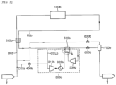
- FIG. 1 is a configuration diagram schematically showing the existing partial re-liquefaction system.
- the boil-off gas generated and discharged from a storage tank storing a fluid cargo is sent along a pipe and compressed by a boil-off gas compressor 10.
- a storage tank T is provided with a sealing and heat insulating barrier to be able to store liquefied gas such as liquefied natural gas at a cryogenic temperature.
- the sealing and heat insulating barrier may not completely shut off heat transmitted from the outside. Therefore, the liquefied gas is continuously evaporated in the storage tank, so an internal pressure of the storage tank may be increased. Accordingly, to prevent the pressure of the tank from excessively increasing due to the boil-off gas and keep the internal pressure of the tank at an appropriate level, the boil-off gas in the storage tank is discharged and is then supplied to the boil-off compressor 10.
- the first flow of the compressed boil-off gas is divided into a second flow and a third stream, and the second flow may be formed to be liquefied and then return to the storage tank T, and the third flow may be formed to be supplied to gas fuel consumption places such as a boost engine and a power generation engine in a ship.
- the boil-off gas compressor 10 can compress the boil-off gas to a supply pressure of the fuel consumption place, and the second flow may be branched via all or a part of the boil-off gas compressor if necessary.
- All of the boil-off gas compressed as the third flow may also be supplied according to the amount of fuel required for the fuel consumption place, and all of the compressed boil-off gas may return to the storage tank by supplying the whole amount of boil-off gas as the second stream.
- An example of the gas fuel consumption places may include a DF generator, a gas turbine, DFDE, and the like, in addition to high pressure gas injection engine (e.g., ME-GI engines developed by MDT Co., etc.) and low-temperature gas injection engines (e.g., generation X-dual fuel engine (X-DF engine) by Wartsila Co.) .
- a heat exchanger 20 is provided to liquefy the second flow of the compressed boil-off gas.
- the boil-off gas generated from the storage tank is used as a cold heat supply source of the compressed boil-off gas.
- the compressed boil-off gas, that is, the second stream, whose temperature rises while being compressed by the boil-off gas compressor while passing through the heat exchanger 20 is cooled, and the boil-off gas generated from the storage tank and introduced into the heat exchanger 20 is heated and then supplied to the boil-off gas compressor 10.
- the second flow of the compressed boil-off gas may be at least partially liquefied by receiving cold heat from the boil-off gas before being compressed.
- the heat exchanger exchanges heat the low-temperature boil-off gas immediately after being discharged from the storage tank with the high-pressure boil-off gas compressed by the boil-off gas compressor to liquefy the high-pressure boil-off gas.
- the boil-off gas of the second flow passing through the heat exchanger 20 is further cooled while being decompressed by passing through an expansion means 30 such as an expansion valve or an expander and is then supplied to a gas-liquid separator 40.
- the gas-liquid separator 40 separates the liquefied boil-off gas into gas and liquid components.
- the liquid component, that is, the liquefied natural gas returns to the storage tank, and the gas component, that is, the boil-off gas is discharged from the storage tank to be joined with a flow of boil-off gas supplied to the heat exchanger 20 and the boil-off gas compressor 10 or is then supplied back to the heat exchanger 20 to be utilized as a cold heat supply source which heat-exchanges high-pressure boil-off gas compressed by the boil-off gas compressor 10.
- the boil-off gas may be sent to a gas combustion unit (GCU) or the like to be combusted or may be sent to a gas consumption place (including a gas engine) to be consumed.
- GCU gas combustion unit
- Another expansion means 50 for additionally decompressing the gas separated by the gas-liquid separator before being joined with the flow of boil-off gas may be further provided.
- FIG. 2 is a configuration diagram schematically showing a boil-off gas treatment system for a ship according to a first embodiment not in accordance with the invention.
- the system of the present embodiment includes a refrigerant circulator 300a which is supplied with boil-off gas generated from a low temperature fluid cargo stored in a storage tank and circulates the boil-off gas as a refrigerant.
- the system includes a refrigerant supply line CSLa which supplies boil-off gas from the storage tank to a refrigerant circulator 300a.
- the refrigerant supply line is provided with a valve 400a to shut off the refrigerant supply line CSLa if a sufficient amount of boil-off gas, which may circulate the refrigerant circulator, is supplied, such that the refrigerant circulator 300a is operated as a closed loop.
- the compressor 100a for compressing the boil-off gas generated from the low-temperature fluid cargo in the storage tank T is also provided.
- the boil-off gas generated from the storage tank is introduced into the compressor 100a along a boil-off gas supply line BLa.
- the storage tank (T) of the present embodiment may be an independent type tank in which a load of the fluid cargo is not directly applied to a heat insulating layer, or a membrane type tank in which the load of the cargo is directly applied to the heat insulating layer.
- the independent type tank can be used as a pressure vessel which is designed to withstand a pressure of 2 barg or more.
- the boil-off gas compressed by the compressor may be supplied as fuel to a fuel consumption place including a boost engine and a power generation engine of a ship or an offshore structure.
- the whole amount of boil-off gas may also be supplied to a re-liquefaction line RLa.
- the compressed boil-off gas is supplied to a boil-off gas heat exchanger 200a along the boil-off gas re-liquefaction line RLa.
- the boil-off gas heat exchanger 200a is provided over the boil-off gas re-liquefaction line RLa and the boil-off gas supply line BLa to exchange heat between boil-off gas introduced into the compressor 100a and the boil-off gas compressed by at least a part of the compressor.
- the boil-off gas whose temperature rises during the compression is cooled through the heat exchange with the low-temperature boil-off gas which is generated from the storage tank and is to be introduced into the compressor 100a.
- a downstream of the boil-off gas heat exchanger 200a is provided with a refrigerant heat exchanger 500a.
- the boil-off gas, which is compressed and then heat-exchanged by the boil-off gas heat exchanger is additionally cooled by the heat exchange with the boil-off gas which circulates the refrigerant circulator 300a.
- the refrigerant circulator 300a includes a refrigerant compressor 310a which compresses the boil-off gas supplied from the storage tank, a cooler 320a which cools the boil-off gas compressed by the refrigerant compressor, and a refrigerant decompressing device 330a which decompresses and additionally cools the boil-off gas cooled by the cooler.
- the refrigerant decompressing device 330a may be an expansion valve or an expander which adiabatically expands and cools the boil-off gas.
- the boil-off gas cooled by the refrigerant decompressing device 330a is supplied as a refrigerant to the refrigerant heat exchanger 500a along the refrigerant circulation line CCLa.
- the refrigerant heat exchanger 500a cools the boil-off gas by the heat exchange with the boil-off gas supplied via the boil-off gas heat exchanger 200a.
- the boil-off gas of the refrigerant circulation line CCLa passing through the refrigerant heat exchanger 500a is circulated to the refrigerant compressor 310a and circulates the refrigerant circulation line while undergoing the above-described compression and cooling processes.
- the first decompressing device 600a may be an expansion valve, such as a Joule-Thomson valve, or an expander.
- the decompressed boil-off gas is separated into gas and liquid by being supplied to a gas-liquid separator 700a on a downstream of the first decompressing device 600a, and the liquid separated by the gas-liquid separator 700a, that is, the liquefied natural gas is supplied to the storage tank T and again stored.
- the gas separated by the gas-liquid separator 700a that is, the boil-off gas is additionally decompressed by a second decompressing device 800a, and is joined with the flow of boil-off gas to be introduced into the boil-off gas heat exchanger 200a from the storage tank T or is supplied to the boil-off gas heat exchanger 200a to be utilized as the cold heat supply source which heat-exchanges a high-pressure boil-off gas compressed by the compressor 100a.
- the boil-off gas may be sent to a gas combustion unit (GCU) or the like to be combusted or may be sent to a fuel consumption place (including a gas engine) to be consumed.
- GCU gas combustion unit
- FIG. 3 is a configuration diagram schematically showing a boil-off gas treatment system for a ship according to a second embodiment not in accordance with the invention.
- the boil-off gas which is to be introduced into a refrigerant decompressing device 330b from a cooler 320b is cooled by exchanging heat with the boil-off gas decompressed by the refrigerant decompressing device 330b and then supplied to the refrigerant decompressing device 330b.
- the boil-off gas downstream of the refrigerant decompressing device has temperature lower than that of the boil-off gas upstream of the refrigerant decompressing device.
- the boil-off gas upstream of the refrigerant decompressing device is cooled by exchanging heat with the boil-off gas downstream of the refrigerant decompressing device and then introduced into the decompressing device.
- the boil-off gas upstream of the refrigerant decompressing device 330b may be supplied to the refrigerant heat exchanger 500b (portion A of FIG. 3 ).
- a separate heat exchanging device which may exchange heat between the boil-off gases upstream and downstream of the refrigerant decompressing device may be additionally provided.
- the system of the present embodiments can re-liquefy and store the boil-off gas generated from the storage tank fluid cargo, thereby increasing the transportation rate of the fluid cargo.
- the gas can be combusted by the gas combustion unit (GCU) or the like to prevent the pressure of the storage tank from increasing to reduce or eliminate the amount of wasted cargo, thereby preventing a waste of energy.
- GCU gas combustion unit
- the boil-off gas is circulated as the refrigerant to be utilized as the cold heat source for re-liquefaction, thereby effectively re-liquefying the boil-off gas without configuring the separate refrigerant cycle, and the separate refrigerant need not be supplied to contribute to securing the in-ship space and increase the economical efficiency.
- the refrigerant may be replenished from the storage tank to be smoothly replenished and the refrigerant cycle may be effectively operated.
- the boil-off gas may be re-liquefied by using the cold heat of the boil-off gas itself in multiple steps, so that the system configuration for treating the in-ship boil-off gas can be simplified and the cost required to install and operate the apparatus for complicated boil-off gas treatment can be saved.
- FIG. 4 is a configuration diagram schematically showing a boil-off gas treatment system for a ship according to a third embodiment not in accordance with the invention.
- the ship of the present embodiment includes: a boil-off gas heat exchanger 110 which is installed on a downstream of the storage tank T; a compressor 120 and a first extra compressor 122 which are installed on a downstream of the boil-off gas heat exchanger 110 to compress boil-off gas discharged from the storage tank T; a cooler 130 which lowers temperature of the boil-off gas compressed by the extra compressor 120; a first extra cooler 132 which lowers the temperature of the boil-off gas compressed by the first extra compressor 122; a first valve 191 which is installed on an upstream of the compressor 120; a second valve 192 which is installed on a downstream of the cooler 130; a third valve 193 which is installed on an upstream of the first extra compressor 122; a fourth valve 194 which is installed on a downstream of the first extra cooler 132; a refrigerant heat exchanger 140 which additionally cools the boil-off gas cooled by the boil-off gas heat exchanger 110; a refrigerant decompressing device 160 which expands
- the boil-off gas which is naturally generated from the storage tank T and then discharged, is supplied to a fuel consumption source 180 along the first supply line L1.
- the ship of the present embodiment may further include an eleventh valve 203 which is installed upstream of the fuel consumption place 180 to control a flow rate of the boil-off gas sent to the fuel consumption place 180 and opening / closing thereof.
- the boil-off gas heat exchanger 110 is installed on the first supply line L1 and recovers cold heat from the boil-off gas immediately after being discharged from the storage tank T.
- the boil-off gas heat exchanger 110 is supplied with the boil-off gas discharged from the storage tank T and uses the boil-off gas supplied to the boil-off gas heat exchanger 110 along the return line L3 as a refrigerant.
- the fifth valve 195 which controls the flow rate of the boil-off gas and opening / closing thereof may be installed on a return line L3.
- the compressor 120 and the first extra compressor 122 compress the boil-off gas passing through the boil-off gas heat exchanger 110.
- the compressor 120 is installed on the first supply line L1 and the first extra compressor 122 is installed on the second supply line L2.
- the second supply line L2 is branched from the first supply line L1 on the upstream of the compressor 120 and connected to the first supply line L1 on the downstream of the compressor 120.
- the compressor 120 and the first extra compressor 122 are installed in parallel, and may have the same performance.
- the ship is additionally provided with the first extra compressor 122 and the first extra cooler 132 for preparing for the case where the compressor 120 and the cooler 130 fail.
- the first extra compressor 122 and the first extra cooler 132 are not used at ordinary times when the compressor 120 or the cooler 130 does not fail.
- the third valve 193 on an upstream of the first extra compressor 122 and the fourth valve 194 on a downstream of the first extra cooler 132 are closed so that the boil-off gas is supplied to the fuel consumption place 180 via the compressor 120 and the cooler 130, and when the compressor 120 or the cooler 130 fails, the third valve 193 on the upstream of the first extra compressor 122 and the fourth valve 194 on the downstream of the first extra cooler 132 are open and the first valve 191 on the upstream of the compressor 120 and the second valve 192 on a downstream of the cooler 130 are closed so that the boil-off gas is supplied to the fuel consumption place 180 via the first extra compressor 122 and the first extra cooler 132.
- the present embodiment increases the re-liquefaction efficiency and re-liquefaction amount of the boil-off gas by using the first extra compressor 122 and the first extra cooler 132 which are not used even if they are installed in the ship, and sends a part of the boil-off gas compressed by the first extra compressor 122 to the fuel consumption place 180 and uses the other part of the boil-off gas as a refrigerant which additionally cools the boil-off gas in the refrigerant heat exchanger 140.
- FIG. 6 is a graph schematically illustrating a phase change of methane depending on temperature and pressure.
- methane becomes a supercritical fluid state at a temperature of approximately -80 oC or higher and a pressure of approximately 55 bars or higher. That is, in the case of methane, a critical point is approximately -80 °C and 55 bars.
- the supercritical fluid state is a third state different from a liquid phase or a gas phase.
- the supercritical fluid states may also be a state in which a density is high, unlike a general liquid phase.
- the state of the boil-off gas having a pressure equal to or higher than the critical point and a temperature equal to lower than the critical point is referred to as a "high-pressure liquid phase”.
- the boil-off gas compressed by the compressor 120 or the first extra compressor 122 may be in a gaseous state or in a supercritical fluid state depending on how much the boil-off gas is compressed.
- the temperature of the boil-off gas is lowered while the boil-off gas passes through the boil-off gas heat exchanger 110, and thus the boil-off gas may be a mixed state of liquid and gas.
- the temperature of the boil-off gas is lowered while the boil-off gas passes through the boil-off gas heat exchanger 110 and thus the boil-off gas may be the "high-pressure liquid phase".
- the temperature of the boil-off gas cooled by the boil-off gas heat exchanger 110 is further lowered while the boil-off gas passes through the refrigerant exchanger 140.
- the temperature of the boil-off gas passing through the boil-off gas heat exchanger 110 is in the mixed state of liquid and gas, the temperature of the boil-off gas is further lowered while the boil-off gas passes through the refrigerant heat exchanger 140 and thus the boil-off gas becomes the mixed state in which a ratio of liquid is higher or becomes the liquid phase and in the case of the "high-pressure liquid phase", the temperature of the boil-off gas is further lowered while the boil-off gas passes through the refrigerant heat exchanger 140.
- the pressure of the boil-off gas is lowered while the boil-off gas passes through the first decompressing device 150, and thus the boil-off gas becomes low in a liquid phase or the mixed state of liquid and gas.
- the boil-off gas becomes the mixed state in which the ration of the liquid is higher in the case where the boil-off gas is decompressed in the higher temperature (X ⁇ X' in FIG. 6 ) than in the case where the boil-off gas is decompressed in the lower temperature (Y ⁇ Y' in FIG. 6 ).
- the temperature may be further lowered, the boil-off gas can theoretically be re-liquefied 100% (Z ⁇ Z 'in FIG. 6 ). Therefore, if the boil-off gas is cooled once more by the refrigerant heat exchanger 140 before passing through the first decompressing device 150, the re-liquefaction efficiency and the liquefaction amount can be increased.
- the present embodiment is different from the first and second embodiments in that the refrigerant cycle is configured as the open loop.
- the refrigerant circulators 300a and 300b are configured as the closed loop, and thus the boil-off gas compressed by the refrigerant compressors 310a and 310b is used only as a refrigerant in the refrigerant heat exchangers 500a and 500b but may not be sent to the fuel consumption place or may not undergo the re-liquefaction process.
- the refrigerant cycle is configured as the open loop, and thus the boil-off gas compressed by the first extra compressor 122 is joined with the boil-off gas compressed by the compressor 120, and then a part of the boil-off gas is sent to the fuel consumption place 180, the other part thereof is used as the refrigerant in the refrigerant heat exchanger 140 along the recirculation line L5, and the remaining part thereof undergoes the re-liquefaction process along the return line L3.
- the recirculation line L5 is a line which is branched from the first supply line L1 on the downstream of the compressor 120 and connected to the first supply line L1 on the upstream of the compressor 120.
- a sixth valve 196 which controls the flow rate of the boil-off gas and the opening / closing thereof may be installed on the recirculation line L5 along which the boil-off gas branched from the first supply line L1 is sent to the refrigerant heat exchanger 140.
- the present embodiment in which the refrigerant cycle is configured as the open loop is greatly different from the first and second embodiments in that the downstream line of the compressor 120 and the downstream line of the first extra compressor 122 are connected. That is, in the present embodiment, the second supply line L2 on the downstream of the first extra compressor 122 is connected to the first supply line L1 on the downstream of the compressor 120, and thus the boil-off gas compressed by the first extra compressor 122 is joined with the boil-off gas compressed by the compressor 120 and then sent to the refrigerant heat exchanger 140, the fuel consumption place 180, or the boil-off gas heat exchanger 110.
- the present embodiment includes all other modifications in which the downstream of the compressor 120 and the downstream line of the first extra compressor 122 are connected.
- the boil-off gas compressed by the first extra compressor 122 as well as the boil-off gas compressed by the compressor 120 as well as the compressed may be sent to the fuel consumption place 180.
- the compressor 120 and the first extra compressor 122 are designed to have a capacity of approximately 1.2 times the amount required in the fuel consumption place 180, the case in which the boil-off gas compressed by the first extra compressor 122 exceeding the capacity of the compressor 120 is sent to the fuel consumption place 180 little occurs. Rather, since the boil-off gas discharged from the storage tank T are entirely not consumed in the fuel consumption place 180 and therefore the boil-off gas to be re-liquefied increases, the case in which a large amount of refrigerant is required to re-liquefy a large amount of boil-off gas is more frequent.
- the boil-off gas supplied to the refrigerant heat exchanger 140 along the return line L3 after passing through the boil-off gas heat exchanger 110 may be cooled to a lower temperature by using more refrigerant and the overall re-liquefaction efficiency and re-liquefaction amount may be increased. Theoretically, 100% re-liquefaction is possible.
- both of the capacity required for supplying the boil-off gas to the fuel consumption place 180 and the capacity required for re-liquefying the boil-off gas remaining by being not completely consumed in the fuel consumption place 180 are considered.
- the capacity required for re-liquefaction may be reduced, and thus small-capacity compressors 120 and 122 can be provided. Reducing the capacity of the compressor can save both equipment installation costs and operating costs.
- the compressor 120 or the cooler 130 at ordinary times when the compressor 120 or the cooler 130 does not fail, not only the first valve 191 and the second valve 192 but also the third valve 193 and the fourth valve 194 are open so that all of the compressor 120, the cooler 130, the first extra compressor 122, and the first extra cooler 132 are operated, and when the compressor 120 or the cooler 130 fails, increasing the re-liquefaction efficiency and the re-liquefaction amount is abandoned and the first valve 191 and the second valve 192 are closed so that the system is operated only by the boil-off gas passing through the first extra compressor 122 and the first extra compressor 132.
- the compressor 120 and the cooler 130 play a major role and the first extra compressor 122 and the first extra cooler 132 play an auxiliary role.
- the compressor 120 and the first extra compressor 122 and the cooler 130 and the first extra cooler 132 play the same role.
- At least two compressors and coolers which play the same role are installed in one ship, and therefore when any one of the two compressors fail, the other unbroken compressor may be used, which may satisfy a redundancy concept.
- the compressor 120 and the first extra compressor 122 may compress the boil-off gas to a pressure required by the fuel consumption place 180.
- the fuel consumption place 180 may be an engine, a generator, or the like which are operated by the boil-off gas as fuel.
- the compressor 120 and the first extra compressor 122 may compress the boil-off gas to a pressure of approximately 10 to 100 bars.
- the compressor 120 and the first extra compressor 122 may also compress the boil-off gas to a pressure of approximately 150 bars to 400 bars when the fuel consumption place 180 is an ME-GI engine, and when the fuel consumption place 180 is a DFDE, the boil-off gas may be compressed to a pressure of approximately 6.5 bars, and when the fuel consumption place 180 is an X-DF engine, the boil-off gas may be compressed to a pressure of approximately 16 bars.
- the fuel consumption place 180 may also include various kinds of engines.
- the compressor 120 and the first extra compressor 122 may compress the boil-off gas to the pressure required by the X-DF engine, and the decompressing device is installed on the upstream of the DFDE to lower a part of the boil-off gas compressed at the pressure required by the X-DF engine to a pressure required by the DFDE and then supply the compressed boil-off gas to the DFDE.
- the compressor 120 or the first extra compressor 122 compresses the boil-off gas so that the pressure of the boil-off gas exceeds the pressure required by the fuel consumption place 180, and the decompressing device is installed on the upstream of the fuel consumption place 180 to lower the pressure of the compressed boil-off gas to exceed the pressure required by the fuel consumption place 180 to the pressure required by the fuel consumption place 180 and then supply the compressed boil-off gas to the fuel consumption place 180.
- the compressor 120 and the first extra compressor 122 may each be a multi-stage compressor.
- FIG. 4 illustrates that one compressor 120 or 122 compresses the boil-off gas to the pressure required by the fuel consumption place 180, but when the compressor 120 and the first extra compressor 122 are a multi-stage compressor, a plurality of compression cylinders may compress the boil-off gas to the pressure required by the fuel consumption place 180 several times.
- the plurality of compression cylinders may be provided in the compressor 120 and the first extra compressor 122 in series and the plurality of coolers may each be provide on the downstream of the plurality of compression cylinders.
- the cooler 130 of the present embodiment is installed downstream of the compressor 120 to cool the boil-off gas which is compressed by the compressor 120 and has the increased pressure and temperature.
- the first extra cooler 132 of the present embodiment is installed downstream of the first extra compressor 122 to cool the boil-off gas which is compressed by the first extra compressor 122 and has the increased pressure and temperature.
- the cooler 130 and the first extra cooler 132 may cool the boil-off gas by exchanging heat with seawater, fresh water, or air introduced from the outside.
- the refrigerant heat exchanger 140 of the present embodiment additionally cools the boil-off gas which is cooled by the boil-off gas heat exchanger 110 and then supplied to the refrigerant heat exchanger 140 along the return line L3.
- the refrigerant decompressing device 160 of the present embodiment expands the boil-off gas which passes through the refrigerant heat exchanger 140 and then sends the expanded boil-off gas back to the refrigerant heat exchanger 140.
- the refrigerant heat exchanger 140 expands the boil-off gas, which passes through the boil-off gas heat exchanger 110 and then supplied to the refrigerant heat exchanger 140 along the return line L3, performs heat exchange by the refrigerant to additionally cool the boil-off gas expanded by the refrigerant decompressing device 160.
- the refrigerant decompressing device 160 of the present embodiment may be various means for lowering the pressure of the fluid, and the state of the fluid just before passing through the refrigerant decompressing device 160 and the state of the fluid just after passing through the refrigerant decompressing device 160 may be changed depending on the operation condition of the system.
- the refrigerant decompressing device 160 is an expander, in order to prevent a physical damage of the refrigerant decompressing device 160, the fluid just before passing through the refrigerant decompressing device 160 and the fluid just after passing through the refrigerant decompressing device 160 is preferably maintained in a gas phase. Next, the above description is applied.
- the boil-off gas used as the refrigerant for the heat exchange in the refrigerant heat exchanger 140 after passing through the refrigerant decompressing device 160, after the boil-off gas compressed by the compressor 120 is joined with the boil-off gas compressed by the first extra compressor 122, a part of the joined boil-off gas is supplied to the refrigerant heat exchanger 140 along the recirculation line L5 and cooled by exchanging heat with the boil-off gas, which passes through the refrigerant decompressing device 160, in the refrigerant heat exchanger 140 by the refrigerant and then supplied to the refrigerant decompressing device 160.
- the boil-off gas supplied from the first supply line L1 to the refrigerant heat exchanger 140 along the first supply line L1 is primarily used in the refrigerant heat exchanger 140 and is additionally cooled by the refrigerant decompressing device 160 and is then sent back to the refrigerant heat exchanger 140, such that the boil-off gas is used as the refrigerant.
- the first decompressing device 150 of the present embodiment is installed on the return line L3 to expand the boil-off gas cooled by the boil-off gas heat exchanger 110 and the refrigerant heat exchanger 140.
- the boil-off gas compressed by the compressor 120 is joined with the boil-off gas compressed by the first extra compressor 122 and then a part of the boil-off gas is branched into pass through the boil-off gas heat exchanger 110, the refrigerant heat exchanger 110 140, and the first decompressing device 150, such that the boil-off gas is partially or totally re-liquefied.
- the first decompressing device 150 includes all means which may expand and cool the boil-off gas, and may be an expansion valve, such as a Joule-Thomson valve, or an expander.
- the ship of the present embodiment may include the gas-liquid separator 170 which is installed on the return line L3 on the downstream of the first decompressing device 150 and separates the gas-liquid mixture discharged from the first decompressing device 150 into gas and liquid.
- the ship of the present embodiment does not include the gas-liquid separator 170, the liquid or the boil-off gas in the gas-liquid mixed state which passes through the first decompressing device 150 is immediately sent to the storage tank T.
- the boil-off gas which passes through the first decompressing device 150 is sent to the gas-liquid separator 170 to separate the gas phase and the liquid phase.
- the liquid separated by the gas-liquid separator 170 returns to the storage tank T along the return line L3 and the gas separated by the gas-liquid separator 170 is supplied to the boil-off gas heat exchanger 110 along a gas discharge line which extends from the gas-liquid separator 170 to the first supply line L1 on the upstream of the boil-off gas heat exchanger 110.
- the ship may further include a seventh valve 197 which controls the flow rate of the liquid separated by the gas-liquid separator 170 and sent to the storage tank T; an eighth valve 198 which controls the flow rate of gas separated by the gas-liquid separator 170 and sent to the boil-off gas heat exchanger 110.
- the first to eighth valves and the eleventh valve 191, 192, 193, 194, 195, 196, 197, 198, and 203 of the present embodiment may be manually controlled by allowing a person to directly determine the operation condition of the system and may be automatically controlled to be opened or closed depending on a preset value.
- a flow in which the boil-off gas generated from the storage tank T and the gas discharged from the gas-liquid separator 170 is supplied to the boil-off gas heat exchanger 110 is defined as a first flow 100
- a flow which is supplied from the boil-off gas heat exchanger 110 to the compressor 120 and the first extra compressor 122 and then discharged from the compressor 120 or the first extra compressor 122 and supplied to the fuel consumption place 180 is defined as a second flow 102
- a flow which is branched from the second flow 102 on the downstream of the compressor 120 and the first extra compressor 122 and the supplied to the refrigerant heat exchanger 140 is defined as a third flow 104
- a flow which is branched from the second flow 102 on the downstream of the compressor 120 and the first extra compressor 122 and supplied to the boil-off gas heat exchanger 110 is defined as a fourth flow 106, and a flow
- the present embodiment is particularly suitable for the case where the liquefied gas stored in the storage tank is liquefied natural gas and the fuel consumption place is X-DF, but is not limited thereto. The same goes for the fourth embodiment.
- the gaseous boil-off gas generated from the storage tank (T) storing the liquefied gas in the liquid phase is supplied to the boil-off gas heat exchanger (110).
- the gaseous boil-off gas generated from the storage tank T meets the gaseous boil-off gas discharged from the gas-liquid separator 170 after the predetermined time elapses from the operation of the system to form the first flow 100.
- the boil-off gas supplied to the boil-off gas heat exchanger 110 becomes the first flow 100.
- the boil-off gas heat exchanger 110 serves to recover the cold heat of the first flow 100 to cool the other boil-off gas. That is, the boil-off heat exchanger 110 recovers the cold heat of the first flow 100 and delvers the recovered cold heat to the flow supplied back to the boil-off heat exchanger 110 in the second flow 102, that is, the fourth flow 106.
- the heat exchange is generated between the first flow 100 and the fourth flow 106 so that the first flow 100 is heated and the fourth flow 106 is cooled.
- the heated first flow 100 becomes the second flow 102 and the cooled fourth flow 106 becomes the fifth flow 108.
- the second flow 102 discharged from the boil-off gas heat exchanger 110 is supplied to the compressor 120 or the first extra compressor 122 and is compressed by the compressor 120 or the first extra compressor 122.
- a part of the second flow 102 in which the boil-off gas compressed by the compressor 120 and the boil-off gas compressed by the first extra compressor 122 are joined is the third flow 104 and supplied to the refrigerant heat exchanger 140 as a refrigerant, and the other part thereof is the fourth flow 106 and is supplied to the boil-off gas heat exchanger 110 to be cooled and the remaining part thereof is supplied to the fuel consumption place 180.
- the third flow 104 supplied to the refrigerant heat exchanger 140 is discharged from the refrigerant heat exchanger 140 and expanded in the refrigerant decompressing device 160 and then supplied back to the refrigerant heat exchanger 140.
- the third flow 104 primarily supplied to the refrigerant heat exchanger 140 is expanded in the refrigerant heat exchanger 140 and then exchanges heat with the third flow 104 supplied back to the refrigerant heat exchanger 140 to be cooled.
- the third flow 104 which passes through the refrigerant decompressing device 160 and the refrigerant heat exchanger 140 is joined with the second flow 102 that is discharged from the boil-off gas heat exchanger 110 and supplied to the compressor 120 or the first extra compressor 122.
- the fourth flow 106 cooled by the heat exchange with the first flow 100 in the boil-off gas heat exchanger 110 becomes the fifth flow 108 and is supplied to the refrigerant heat exchanger 140.
- the fifth flow 108 supplied to the refrigerant heat exchanger 140 exchanges heat with the third flow 104 which passes through the refrigerant decompressing device 160 and is cooled, and then passes through the first decompressing device 150 and expanded.
- the fifth flow 108 which passes through the first decompressing device 150 becomes a gas-liquid mixture state in which gas and liquid are mixed.
- the fifth flow 108 in the gas-liquid mixture state is immediately sent to the storage tank T or separated into gas and liquid while passing through the gas-liquid separator 170.
- the liquid separated by the gas-liquid separator 170 is supplied to the storage tank T and the gas separated by the gas-liquid separator 170 is supplied back to the boil-off gas heat exchanger 110, thereby repeating the above-mentioned series of processes.
- FIG. 5 is a configuration diagram schematically showing a boil-off gas treatment system for a ship according to a fourth embodiment in accordance with the present invention.
- the ship of the fourth embodiment shown in FIG. 5 is different from the ship of the third embodiment shown in FIG. 4 in that the ship further includes a boost compressor 124 which is installed on the return line; and a boost cooler 134 which is installed downstream of the boost compressor 124 to increase the re-liquefaction efficiency and the re-liquefaction amount in the boil-off gas heat exchanger 110 and further includes the ninth valve 201, the tenth valve 202, and the first additional line L6 and may configure the system so that the refrigerant cycle is operated as the closed loop as in the first and second embodiments and the refrigerant cycle is operated as the open loop as in the third embodiment by modifying a part of the line along which the boil-off gas flows.
- the detailed description of the same member as the ship of the foregoing third embodiment will be omitted.
- the ship of the present embodiment includes the boil-off gas heat exchanger 110, the first valve 191, the compressor 120, the cooler 130, the second valve 192, the third valve 193, the extra compressor 122, the extra cooler 132, the fourth valve 194, the refrigerant heat exchanger 140, the refrigerant decompressing device 160, and the first decompressing device 150.
- the storage tank T stores liquefied gas such as liquefied natural gas and liquefied ethane gas, and discharges the boil-off gas to the outside when the internal pressure of the storage tank T exceeds a certain pressure or higher.
- the boil-off gas discharged from the storage tank (T) is sent to the boil-off gas heat exchanger 110.
- the boil-off gas heat exchanger 110 of the present embodiment uses the boil-off gas discharged from the storage tank T as the refrigerant and cools the boil-off gas supplied to the boil-off gas heat exchanger 110 along the return line L3. That is, the boil-off gas heat exchanger 110 recovers the cold heat of the boil-off gas discharged from the storage tank T and supplies the recovered cold heat to the boil-off gas sent to the boil-off gas heat exchanger 110 along the return line L3.
- the fifth valve 195 which controls the flow rate of the boil-off gas and opening / closing thereof may be installed on a return line L3.
- the compressor 120 of the present embodiment is installed on the first supply line L1 to compress the boil-off gas discharged from the storage tank T and similar to the third embodiment, the extra compressor 122 of the present embodiment is installed in parallel with the compressor 120 on the second supply line L2 to compress the boil-off gas discharged from the storage tank T.
- the compressor 120 and the extra compressor 122 may be a compressor having the same performance, and each may be a multi-stage compressor.
- the compressor 120 and the extra compressor 122 of the present embodiment may compress the boil-off gas to the pressure required by the fuel consumption place 180.
- the fuel consumption place 180 includes various kinds of engines, after the boil-off gas is compressed according to the required pressure of the engine requiring a higher pressure (hereinafter referred to as a ⁇ high pressure engine'), a part of the boil-off gas is supplied to the high pressure engine and the other part thereof is supplied to the engine (hereinafter, referred to as 'low pressure engine,) requiring a lower pressure.
- the boil-off gas may be decompressed by the decompressing device installed on the upstream and supplied to the low pressure engine.
- the compressor 120 or the extra compressor 122 compresses the boil-off gas to a pressure equal to or higher than the pressure required by the fuel consumption place 180, and the decompressing device is installed on the fuel consumption place 180 to lower the pressure of the boil-off gas compressed at the high pressure to the pressure required by the fuel consumption place 180 and then supply the decompressed boil-off gas to the fuel consumption place 180.
- the ship of the present embodiment may further include an eleventh valve 203 which is installed upstream of the fuel consumption place 180 to control a flow rate of the boil-off gas sent to the fuel consumption place 180 and opening / closing thereof.
- the ship of the present embodiment uses the boil-off gas compressed by the extra compressor 122 as the refrigerant which additionally cools the boil-off gas in the refrigerant heat exchanger 140, thereby increasing the re-liquefaction efficiency and the re-liquefaction amount.
- the cooler 130 of the present embodiment is installed downstream of the compressor 120 to cool the boil-off gas that passes through the compressor 120 and has the increased pressure and temperature.
- the extra cooler 132 of the present embodiment is installed downstream of the extra compressor 122 to cool the boil-off gas which passes through the extra compressor 122 and has the increased pressure and temperature.
- the refrigerant heat exchanger 140 of the present embodiment additionally cools the boil-off gas which is supplied to the boil-off gas heat exchanger 110 along the return line L3 and cooled by the boil-off gas heat exchanger 110.
- the boil-off gas discharged from the storage tank T is further cooled not only in the boil-off gas heat exchanger 110 but also in the refrigerant heat exchanger 140, and is supplied to the first decompressing device 150 in the state in which the temperature is lower, thereby increasing the re-liquefaction efficiency and the re-liquefaction amount.
- the refrigerant decompressing device 160 of the present embodiment expands the boil-off gas which passes through the refrigerant heat exchanger 140, and then sends the expanded boil-off gas back to the refrigerant heat exchanger 140.
- the first decompressing device 150 of the present embodiment is installed on the return line L3 to expand the boil-off gas cooled by the boil-off gas heat exchanger 110 and the refrigerant heat exchanger 140.
- the first decompressing device 150 of the present embodiment includes all means which may expand and cool the boil-off gas, and may be an expansion valve, such as a Joule-Thomson valve, or an expander.
- the ship of the present embodiment may include the gas-liquid separator 170 which is installed on the return line L3 on the downstream of the first decompressing device 150 and separates the gas-liquid mixture discharged from the first decompressing device 150 into gas and liquid.
- the ship of the present embodiment does not include the gas-liquid separator 170
- the liquid or the boil-off gas in the gas-liquid mixed state which passes through the first decompressing device 150 is directly sent to the storage tank T
- the ship of the present embodiment includes the gas-liquid separator 170
- the boil-off gas which passes through the first decompressing device 150 is sent to the gas-liquid separator 170 to be separated into the gas phase and the liquid phase.
- the liquid separated by the gas-liquid separator 170 returns to the storage tank T along the return line L3 and the gas separated by the gas-liquid separator 170 is supplied to the boil-off gas heat exchanger 110 along a gas discharge line which extends from the gas-liquid separator 170 to the first supply line L1 on the upstream of the boil-off gas heat exchanger 110.
- the ship of the present embodiment when the ship of the present embodiment includes the gas-liquid separator 170, the ship may further include a seventh valve 197 which controls the flow rate of the liquid separated by the gas-liquid separator 170 and sent to the storage tank T; an eighth valve 198 which controls the flow rate of gas separated by the gas-liquid separator 170 and sent to the boil-off gas heat exchanger 110.
- a seventh valve 197 which controls the flow rate of the liquid separated by the gas-liquid separator 170 and sent to the storage tank T
- an eighth valve 198 which controls the flow rate of gas separated by the gas-liquid separator 170 and sent to the boil-off gas heat exchanger 110.
- the ship of the present embodiment is different from the third embodiment in that the ship further includes the boost compressor 124 which is installed on the return line L3 and the boost cooler 134 which is installed on the return line L3 on the downstream of the boost compressor 124.
- the boost compressor 124 of the present embodiment is installed on the return line L3 on which a part of the boil-off gas supplied to the fuel consumption place 180 along the first supply line L1 is branched to be sent to the boil-off gas heat exchanger 110, thereby increasing the pressure of the boil-off gas supplied to the boil-off gas heat exchanger 110 along the return line L3.
- the boost compressor 124 may compress the boil-off gas to the pressure equal to or lower than a critical point (in the case of methane, approximately 55 bars) or a pressure exceeding the critical point, and the boost compressor 124 of the present embodiment may compress the boil-off gas to approximately 300 bars if the boil-off gas is compressed to a pressure equal to or higher than the critical point.
- the boost cooler 134 of the present embodiment is installed on the return line L3 on the downstream of the boost compressor 124 to lower the boil-off gas which passes through the boost compressor 124 and has not only the reduced pressure but also the increased temperature.
- the ship of the present embodiment further includes the boost compressor 124 to increase the pressure of the boil-off gas undergoing the re-liquefaction process, thereby increasing the re-liquefaction efficiency and the re-liquefaction amount.
- FIGS. 7A and 7B are graphs showing temperature values of methane depending on a heat flow under different pressures. Referring to FIG. 7A and 78B, it can be appreciated that the higher the pressure of the boil-off gas undergoing the re-liquefaction process, the higher the self-heat exchange efficiency becomes.
- the 'self-' of the self-heat exchange means the heat exchange with the high-temperature boil-off gas by the low-temperature boil-off gas itself as the cooling fluid.
- FIG. 7A shows the state of each fluid in the refrigerant heat exchanger 140 when the boost compressor 124 and the boost cooler 134 are not included
- FIG. 7B shows the state of each fluid in the refrigerant heat exchanger 124 when the boost compressor 124 and the boost cooler 134 are included.
- Graph I at the uppermost side in FIGS. 7A and 7B shows the fluid state at point I in FIG. 5 to which the refrigerant heat exchanger 140 is supplied along the recirculation line L5
- graph L at the lowest side shows the fluid state of point K in FIG. 5 which is supplied back to the refrigerant heat exchanger 140 to be used as the refrigerant after passing through the refrigerant heat exchanger 140 and the refrigerant decompressing device 160 along the recirculation line L5
- graph J overlapping with graph K of an intermediate part shows the fluid state at point F in FIG. 5 which is supplied to the refrigerant heat exchanger 140 along the return line L3 after passing through the boil-off heat exchanger 110.
- the graph L proceeds from the left to the right as time passes, and since the fluid cooled by the heat exchange with the refrigerant is supplied with the cold heat from the refrigerant during the heat exchange process and the temperature thereof is reduced, the graphs I and J proceed from the right to the left as time passes.
- the graph K at the intermediate part of FIGS. 7A and 7B is shown by a combination of the graph I and the graph J. That is, the fluid used as the refrigerant in the refrigerant heat exchanger 140 is drawn by the graph L, and the fluid cooled by the heat exchange with the refrigerant in the refrigerant heat exchanger 140 is drawn by the graph K.
- the heat exchanger is designed so that the temperature and the heat flow of the fluid supplied (i.e., the points I, K, and F in FIG. 5 ) to the heat exchanger may be fixed, the temperature of the fluid used as the refrigerant may not be higher than the temperature of the fluid to be cooled, and a logarithmic mean temperature difference (LMTD) may be as small as possible.
- LMTD logarithmic mean temperature difference
- the smaller the logarithmic mean temperature difference the higher the efficiency of the heat exchanger.
- the logarithmic mean temperature difference is represented by an interval between the low-temperature fluid (graph L in FIG. 7A and 7B ) used as the refrigerant and the high-temperature fluid (graph K in FIG. 7A and 7B ) cooled by the heat exchange with the coolant.
- the interval between the graph L and the graph K shown in FIG. 7B is narrower than the interval between the graph L and the graph K shown in FIG. 7A .
- the fluid at the point F in FIG. 5 may be approximately - 111 °C and 20 bars, and in the case of FIG. 7B which includes the boost compressor 124, the fluid at the point F in FIG. 5 may be approximately -90 °C and 50 bars. If the heat exchanger is designed so that the LMTD is smallest under the initial condition, in the case of FIG. 7B in which the pressure of the boil-off gas undergoing the re-liquefaction process is high, the efficiency of the heat exchanger is higher, such that the liquefaction amount and the re-liquefaction efficiency of the overall system are increased.
- the ship of the present embodiment since the ship of the present embodiment includes the boost compressor 124, it is possible to increase the re-liquefaction amount and the re-liquefaction efficiency, and since the case in which the boil-off gas can be completely treated without operating the extra compressor 122 by increasing the re-liquefaction amount and the re-liquefaction efficiency, the use frequency of the extra compressor can be reduced.
- the re-liquefaction efficiency can be increased by using the extra compressor 122, the longer the time to operate the extra compressor 122, the weaker the redundancy concept for preparing for the failure of the compressor 120.
- the ship of the present embodiment can reduce the use frequency of the extra compressor 122 including the boost compressor 124, and therefore the redundancy concept can be sufficiently secured.
- the boost compressor 124 is generally sufficient to have approximately one half capacity of the compressor 120 or the extra compressor 122, the operation cost may be more saved in the case in which the system is operated by operating only the boost compressor 124 and the compressor 120 without operating the extra compressor 122 than in the case in which the system is operated only by the compressor 120 and the extra compressor 122 without the installation of the boost compressor 124.
- the ship of the present embodiment has a first additional line L6 connecting between the recirculation line L5 and the second supply line L2; a ninth valve 201 installed on the recirculation line L5; and a tenth valve 202 installed on the first additional line L6.
- the first to eighth valves and the eleventh valve 191, 192, 193, 194, 195, 196, 197, 198, 201, 202 and 203 of the present embodiment may be manually controlled by allowing a person to directly determine the operation condition of the system and may be automatically controlled to be opened or closed depending on a preset value.
- One side of the first additional line L6 of the present embodiment is connected to a recirculation line L5, supplying boil-off gas which is expanded by the refrigerant decompressing device 160 and then sent to the first supply line L1 through the refrigerant heat exchanger 140, and the other side thereof is connected to the second supply line L2 between the third valve 193 and the extra compressor 122.
- the ninth valve 201 of the present embodiment is installed on the recirculation line L5 between the point where the recirculation line L5 meets the first supply line L1 on the upstream of the compressor 120 and the extra compressor 122 and the point where the recirculation line L5 meets the first additional line L6.
- the ship of the present embodiment is different from the third embodiment in that the second supply line L2 on the downstream of the extra compressor 122 is connected to the recirculation line L5 instead of the first supply line L1.
- the ship of the present embodiment according to the invention allows that the refrigerant cycle may be operated not only as the open loop but also as the closed loop so as to more flexibly use the re-liquefaction system according to the operating conditions of the ship.
- a method of operating a refrigerant cycle as the closed loop and a method of operating a refrigerant cycle as the open loop by a valve control will be described.
- the system is operated while the first valve 191, the second valve 192, the third valve 193, the fourth valve 194, and the tenth valve 202 are open, and the sixth valve 196 and the ninth valve 201 is closed.
- the third valve 193 is closed to form the refrigerant cycle of the closed loop in which the boil-off gas circulates the extra compressor 122, the extra cooler 132, the fourth valve 194, the refrigerant heat exchanger 140, the refrigerant decompressing device 160, the refrigerant heat exchanger 140, and the tenth valve 202.
- the storage tank of the present embodiment may further include a pipe through which nitrogen gas is introduced into the refrigerant cycle of the closed loop.
- the refrigerant cycle When the refrigerant cycle is operated as the closed loop, only the boil-off gas circulating the closed loop is used as the refrigerant in the refrigerant heat exchanger 140.
- the boil-off gas passing through the compressor 120 is not introduced into the refrigerant cycle but is supplied to the fuel consumption place 180 or undergoes the re-liquefaction process along the return line L3. Therefore, a predetermined flow rate of boil-off gas is circulated as the refrigerant in the refrigerant heat exchanger 140 irrespective of the re-liquefaction amount or the amount of boil-off gas required by the fuel consumption place 180.
- the boil-off gas discharged from the storage tank T passes through the boil-off gas heat exchanger 110 and then compressed by the compressor 120, and a part thereof is cooled by the cooler 130 and then sent to the fuel consumption place 180, and the remaining part thereof undergoes the re-liquefaction process along the return line L3.
- the boil-off gas undergoing the re-liquefaction process along the return line L3 is compressed by the boost compressor 124 and is cooled by exchanging heat with the boil-off gas which is compressed by the boost compressor 124, cooled by the boost cooler 134, and then discharged from the storage tank T by the boil-off gas heat exchanger 110.
- the boil-off gas cooled by the boil-off gas heat exchanger 110 is additionally cooled by the heat exchange in the refrigerant heat exchanger 140 and then expanded by the first decompressing device 150, such that the boil-off gas is partially or totally re-liquefied.
- the boil-off gas partially or totally re-liquefied is directly sent to the storage tank T.
- the boil-off gas partially or totally re-liquefied is sent to the gas-liquid separator 170.
- the gas separated by the gas-liquid separator 170 is joined with the boil-off gas discharged from the storage tank T and sent to the boil-off gas heat exchanger 110.
- the liquid separated by the gas-liquid separator 170 is supplied to the storage tank T.
- the boil-off gas circulating the refrigerant cycle is compressed by the extra compressor 122, cooled by the extra cooler 132, and then sent to the refrigerant heat exchanger 140 along the recirculation line L5.
- the boil-off gas which passes through the extra compressor 122 and the extra cooler 132 and then sent to the refrigerant heat exchanger 140 is primarily heat-exchanged in the refrigerant heat exchanger 140 to be cooled and then sent to the refrigerant decompressing device 160 to be secondarily expanded and cooled.
- the boil-off gas which passes through the refrigerant decompressing device 160 is sent back to the refrigerant heat exchanger 140 to be used as a refrigerant which cools the boil-off gas passing through the boil-off gas heat exchanger 110 and then supplied to the refrigerant heat exchanger 140 along the return line L3 and the boil-off gas compressed by the extra compressor 122 and then supplied to the refrigerant heat exchanger 140 along the recirculation line L5.
- the boil-off gas which passes through the refrigerant decompressing device 160 and then used as the refrigerant in the refrigerant heat exchanger 140 is sent back to the extra compressor 122, thereby repeating the above-mentioned series of processes.
- the first valve 191, the second valve 192, and the tenth valve 202 are closed and the third valve 193 and the sixth valve 196 are open to allow the boil-off gas which is discharged from the storage tank T and then passes through the boil-off gas heat exchanger 110 to be supplied to the fuel consumption place 180 via the third valve 193, the extra compressor 122, the extra cooler 132, the fourth valve 194, and the sixth valve 196.
- the ninth valve 201 may be open to operate the system.
- the first valve 191, the second valve 192, the third valve 193, the fourth valve 194, and the ninth valve 201 are open, and the tenth valve 202 are closed.
- the boil-off gas circulating the refrigerant cycle and the boil-off gas sent to the fuel consumption place 180 or undergoing the re-liquefaction process along the return line L3 are separated.
- the refrigerant cycle is operated as the open loop, the boil-off gas compressed by the compressor 120 and the boil-off gas compressed by the extra compressor 122 are joined to be used as a refrigerant in the refrigerant heat exchanger 140, to be sent to the high pressure engine 180, or to undergo the re-liquefying process along the return line L3.
- the flow rate of the refrigerant to be sent to the refrigerant heat exchanger 140 may be flexibly controlled in consideration of the re-liquefaction amount and the amount of boil-off gas required by the fuel consumption place 180.
- the amount of boil-off gas required by the fuel consumption place 180 is small, increasing the flow rate of the refrigerant sent to the refrigerant heat exchanger 140 may increase the re-liquefaction efficiency and the re-liquefaction amount.
- the refrigerant cycle when the refrigerant cycle is operated as the closed loop, it is not possible to supply the refrigerant heat exchanger 140 with the boil-off gas equal to or more than the capacity of the extra compressor 122.
- the boil-off gas having a flow rate exceeding the capacity of the extra compressor 122 may be supplied to the refrigerant heat exchanger 140.
- the boil-off gas discharged from the storage tank T is branched into two flows after passing through the boil-off gas heat exchanger 110 and a part thereof is sent to the first supply line L1 and the remaining part thereof is supplied to the second supply line L2.
- the boil-off gas sent to the first supply line L1 passes through the first valve 191, the compressor 120, the cooler 130, and the second valve 192 and then a part thereof passes through the sixth valve 196 and is sent to the refrigerant heat exchanger 140, and the other part thereof is again branched into two flows.
- One flow of the boil-off gases branched into the two flows is sent to the fuel consumption place 180 and the other thereof is sent to the boost compressor 124 along the return line L3.
- the boil-off gas sent to the second supply line L1 passes through the third valve 193, the extra compressor 122, the extra cooler 132, and the fourth valve 194 and then a part thereof is sent to the refrigerant heat exchanger 140 and the other part thereof is sent to the first supply line L1 and then branched into two flows.
- One flow of the boil-off gases branched into the two flows is sent to the fuel consumption place 180 and the other thereof is sent to the boost compressor 124 along the return line L3.
- each of the boil-off gas compressed by the compressor 120 and the boil-off gas compressed by the extra compressor 122 does not flow separately but is joined to be supplied to the refrigerant heat exchanger 140, the fuel consumption place 180, or the boost compressor 124.
- the boil-off gas compressed by the compressor 120 and the boil-off gas compressed by the extra compressor 122 are mixed, which in turn flows in the recirculation line L5 along which the boil-off gas is sent to the refrigerant heat exchanger 140, the first supply line L1 along which the boil-off gas is sent to the fuel consumption place 180, and the return line along which the boil-off gas is sent to the boost compressor 124.
- the boil-off gas sent to the refrigerant heat exchanger 140 along the recirculation line L5 is primarily heat-exchanged in the refrigerant heat exchanger 140 to be cooled, and secondarily expanded by the refrigerant decompressing device 160 to be cooled and supplied back to the refrigerant heat exchanger 140.
- the boil-off gas which passes through the refrigerant decompressing device 160 and is then supplied to the refrigerant heat exchanger 140 is used as the refrigerant which cools both of the boil-off gas passing through the boil-off gas heat exchanger 110 and then supplied to the refrigerant heat exchanger 140 along the return line L3 and the confluent flow of the boil-off gas compressed by the compressor 120 and the boil-off gas compressed by the extra compressor 122 which are supplied to the refrigerant heat exchanger 140 along the recirculation line L5.
- the boil-off gas used as the refrigerant in the refrigerant heat exchanger 140 is supplied to the refrigerant heat exchanger 140 along the recirculation line L5, and then primarily cooled by the refrigerant heat exchanger 140 and secondarily cooled by the refrigerant decompressing device 160.
- the boil-off gas sent from the compressor 120 or the extra compressor 122 to the refrigerant heat exchanger 140 along the recirculation line L5 is primarily cooled by the boil-off gas, which passes through the refrigerant decompressing device 160, as the refrigerant.
- the boil-off gas used as the refrigerant in the refrigerant heat exchanger 140 after passing through the refrigerant decompressing device 160 is sent to the first supply line L1 through the ninth valve 201 to be discharged from the storage tank T and then joins with the boil-off gas passing through the boil-off gas heat exchanger 110, thereby repeating the above-mentioned series of processes.
- the boil-off gas sent to the boost compressor 124 along the return line L3 is compressed by the boost compressor 124, cooled by the boost cooler 134, and then sent to the boil-off gas heat exchanger 110.
- the boil-off gas sent to the boil-off gas heat exchanger 110 is primarily cooled by the boil-off gas heat exchanger 110, secondarily cooled by the refrigerant heat exchanger 140, and then expanded by the first decompressing device 150, such that the boil-off gas is partially or totally re-liquefied.
- the boil-off gas partially or totally re-liquefied is directly sent to the storage tank T.
- the boil-off gas partially or totally re-liquefied is sent to the gas-liquid separator 170.
- the gas separated by the gas-liquid separator 170 is joined with the boil-off gas discharged from the storage tank T and sent to the boil-off gas heat exchanger 110.
- the liquid separated by the gas-liquid separator 170 is supplied to the storage tank T.
- the first valve 191, the second valve 192, and the ninth valve 201 are closed to allow the boil-off gas which is discharged from the storage tank T and then passes through the boil-off gas heat exchanger 110 to be supplied to the fuel consumption place 180 via the third valve 193, the extra compressor 122, the extra cooler 132, the fourth valve 194, and the sixth valve 196.
- the ninth valve 201 may be open to operate the system.
- the refrigerant cycle of the ship of the present embodiment When the refrigerant cycle of the ship of the present embodiment is operated as the open loop, the liquefied gas stored in the storage tank T is liquefied natural gas, the fuel consumption place 180 is the X-DF engine, and the refrigerant cycle includes the gas-liquid separator 170, temperatures and pressures of fluid at each point will be described as an example.
- Boil-off gas at point A where the boil-off gas discharged from the storage tank T and the boil-off gas separated by the gas-liquid separator 170 are joined and supplied to the boil-off gas heat exchanger 110 may be approximately -123 °C and 1.060 bara, and boil-off gas at point B after the boil-off gas of approximately -123 °C and 1.060 bara exchanges heat with the boil-off gas of 43 °C and 301.1 bara in the boil-off gas heat exchanger 110 may be approximately 40 °C and 0.96 bara.
- the boil-off gas of approximately 40 °C and 0.96 bara passes through the refrigerant decompressing device 160 and then joined with the boil-off gas of approximately 37 °C and 0.96 bara passing through the refrigerant heat exchanger 140 and then the boil-off gas at point C may be approximately 38 °C and 0.96 bara.
- the boil-off gas of approximately 38 °C and 0.96 bara is branched into two, and one flow is compressed by the compressor 120 and then cooled by the cooler 130, the other flow is compressed by the extra compressor 122 and is then cooled by the extra cooler 132.
- the boil-off gas at point D and the boil-off gas at point I which are the confluent flow of the flow passing through the compressor 120 and the cooler 130 and the flow passing through the extra compressor 122 and the extra cooler 132 may be approximately 43 °C and 17 bara.
- the boil-off gas at the point E after the boil-off gas of approximately 43 °C and 17 bara is compressed by the boost compressor 124 and cooled by the boost cooler 134 may be approximately 43 °C and 301.1 bara
- the boil-off gas at the point F after the boil-off gas of approximately 43 °C and 301.1 bara exchanges heat with the boil-off gas of approximately -123 °C and 1.060 bara in the boil-off gas heat exchanger 110 may be approximately -82 °C and 301 bara.
- the boil-off gas at the point G after the boil-off gas of approximately -82 °C and 301 bara is cooled by the refrigerant heat exchanger may be approximately -153 °C and 300.5 bara
- the boil-off gas at the point H after the boil-off gas of approximately - 153 °C and 300.5 bara is expanded by the first decompressing device 150 may be -155.6 °C and 2.1 bara.
- the boil-off gas at point I after the boil-off gas of approximately 43 °C and 17 bara is primarily cooled by the refrigerant heat exchanger 140 may be approximately -82 °C and 16.5 bara
- the boil-off gas at point J after the boil-off gas of approximately -82 °C and 16.5 bara is secondarily cooled by the refrigerant decompressing device 160 may be approximately -155 °C and 1.56 bara
- the boil-off gas at point K after the boil-off gas of approximately -155 °C and 1.56 bara is used in the refrigerant heat exchanger 140 may be approximately 37 °C and 0.96 bara.
- the ship of the present embodiment may be independently operated while operating the refrigerant cycle as the open loop so that the boil-off gas compressed by the extra compressor 122 is used only as the refrigerant of the refrigerant heat exchanger 140, the boil-off gas compressed by the compressor 120 is sent to the fuel consumption place 180 or undergoes the re-liquefaction process along the return line L3 and is not used as the refrigerant of the refrigerant heat exchanger 140.
- the refrigerant cycle of the open loop in which the extra compressor 122 and the compressor 120 are operated independently is referred to as an independent open loop'.
- the first valve 191, the second valve 192, the third valve 193, the fourth valve 194, and the ninth valve 201 are open, and the sixth valve 196 and the tenth valve 202 are closed.
- the system can be operated more easily than when the open loop is operated.
- the boil-off gas discharged from the storage tank T is branched into two flows after passing through the boil-off gas heat exchanger 110 and a part thereof is sent to the first supply line L1 and the remaining part thereof is supplied to the second supply line L2.
- the boil-off gas sent to the first supply line L1 passes through the first valve 191, the compressor 120, the cooler 130, and the second valve 192 and then a part thereof is sent to the fuel consumption place 180 and the other part thereof is sent to the boost compressor 124 along the return line L3.
- the boil-off gas sent to the second supply line L2 passes through the third valve 193, the extra compressor 122, the extra cooler 132, and the fourth valve 194 and is then sent to the refrigerant heat exchanger 140 along the recirculation line L5.
- the boil-off gas which is compressed by the extra compressor 122 and then sent to the refrigerant heat exchanger 140 along the recirculation line L5 is used as the refrigerant which cools the boil-off gas which is primarily heat-exchanged in the refrigerant heat exchanger 140 to be cooled, secondarily expanded by the refrigerant decompressing device 160 to be cooled, and then supplied back to the refrigerant heat exchanger 140 to pass through the boil-off gas heat exchanger 110 and then be supplied to the refrigerant heat exchanger 140 via the return line L3 and the boil-off gas which is compressed by the extra compressor 122 and then supplied to the refrigerant heat exchanger 140 along the recirculation line L5.
- the boil-off gas used as the refrigerant in the refrigerant heat exchanger 140 after passing through the refrigerant decompressing device 160 is sent to the first supply line L1 through the ninth valve 201 to be discharged from the storage tank T and then joins with the boil-off gas passing through the boil-off gas heat exchanger 110, thereby repeating the above-mentioned series of processes.
- the boil-off gas which is compressed by the compressor 120 and then sent to the boost compressor 124 along the return line L3 is compressed by the boost compressor 124, cooled by the boost cooler 134, and then sent to the boil-off gas heat exchanger 110.
- the boil-off gas sent to the boil-off gas heat exchanger 110 is primarily cooled by the boil-off gas heat exchanger 110, secondarily cooled by the refrigerant heat exchanger 140, and then expanded by the first decompressing device 150, such that the boil-off gas is partially or totally re-liquefied.
- the boil-off gas partially or totally re-liquefied is directly sent to the storage tank T.
- the boil-off gas partially or totally re-liquefied is sent to the gas-liquid separator 170.
- the gas separated by the gas-liquid separator 170 is joined with the boil-off gas discharged from the storage tank T and sent to the boil-off gas heat exchanger 110.
- the liquid separated by the gas-liquid separator 170 is supplied to the storage tank T.
- the first valve 191, the second valve 192, and the ninth valve 201 are closed and the sixth valve 196 is open to allow the boil-off gas which is discharged from the storage tank T and then passes through the boil-off gas heat exchanger 110 to be supplied to the fuel consumption place 180 via the third valve 193, the extra compressor 122, the extra cooler 132, the fourth valve 194, and the sixth valve 196.
- the ninth valve 201 may be open to operate the system.
Description
- The present invention relates to a boil-off gas treatment system and a ship comprising such system, and more particularly, to a ship including a system for re-liquefying boil-off gas left after being used as fuel of an engine among boil-off gases generated in a storage tank.
- In recent years, consumption of liquefied gas such as liquefied natural gas (LNG) has been rapidly increasing worldwide. Since a volume of liquefied gas obtained by liquefying gas at a low temperature is much smaller than that of gas, the liquefied gas has an advantage of being able to increase storage and transport efficiency. In addition, the liquefied gas, including liquefied natural gas, can remove or reduce air pollutants during the liquefaction process, and therefore may also be considered as eco-friendly fuel with less emission of air pollutants during combustion.
- The liquefied natural gas is a colorless transparent liquid obtained by cooling and liquefying methane-based natural gas to about -162 °C, and has about 1/600 less volume than that of natural gas. Therefore, to very efficiently transport the natural gas, the natural gas needs to be liquefied and transported.
- However, since the liquefaction temperature of the natural gas is a cryogenic temperature of -162 °C at normal pressure, the liquefied natural gas is sensitive to temperature change and easily boiled-off. As a result, the storage tank storing the liquefied natural gas is subjected to a heat insulating process. However, since external heat is continuously sent to the storage tank, boil-off gas (BOG) is generated as the liquefied natural gas is continuously vaporized naturally in the storage tank during transportation of the liquefied natural gas. This goes the same for other low-temperature liquefied gases such as ethane.
- The boil-off gas is a kind of loss and is an important problem in transportation efficiency. In addition, if the boil-off gas is accumulated in the storage tank, an internal pressure of the tank may rise excessively, and if the internal pressure of the tank becomes more severe, the tank is highly likely to be damaged. Accordingly, various methods for treating the boil-off gas generated in the storage tank have been studied. Recently, to treat the boil-off gas, a method for re-liquefying boil-off gas and returning the re-liquefied boil-off gas to the storage tank, a method for using boil-off gas as an energy source for fuel consumption places like an engine of a ship, or the like have been used.
- As the method for re-liquefying boil-off gas, there are a method for re-liquefying boil-off gas by heat-exchanging the boil-off gas with a refrigerant by a refrigeration cycle using a separate refrigerant, a method for re-liquefying boil-off gas by the boil-off gas itself as a refrigerant without using a separate refrigerant, or the like. In particular, the system employing the latter method is called a partial re-liquefaction System (PRS).
- Generally, on the other hand, as engines which can use natural gas as fuel among engines used for a ship, there are gas fuel engines such as a DFDE engine and an ME-GI engine.
- The DFDE engine adopts an Otto cycle which consists of four strokes and injects natural gas with a relatively low pressure of approximately 6.5 bars into a combustion air inlet and compresses the natural gas as the piston lifts up.
- The ME-GI engine adopts a diesel cycle which consists of two strokes and employs a diesel cycle which directly injects high pressure natural gas near 300 bars into the combustion chamber around a top dead point of the piston. Recently, there is a growing interest in the ME-GI engine, which has better fuel efficiency and boost efficiency.
-
KR101511214 (B1 -
JP3213846B - An object of the present invention is to provide a ship including a system capable of providing better boil-off gas re-liquefying performance than the existing partial re-liquefaction system.
- A boil-off gas treatment system for a ship including a storage tank storing liquefied gas according to the invention is defined by independent claim 1. Preferred embodiments of the inventive system are presented in the dependent claims.
- The system of the present invention ensures re-liquefaction efficiency since the boil-off gas is decompressed after undergoing the additional cooling process by the refrigerant heat exchanger. In particular, most or all of the remaining boil-off gas can be re-liquefied without employing the refrigeration cycle using the separate refrigerant, and therefore increasing the economical efficiency.
- Further, according to the present invention, it is possible to flexibly control the refrigerant flow rate and the supply of cold heat in response to the discharge amount of the boil-off gas, the engine load depending on the operating speed of the ship, and the like.
- According to the embodiment of the present invention, it is possible to contribute to securing the space on the ship and save the cost of additionally installing the compressor by increasing the re-liquefaction efficiency and the re-liquefaction amount by using the extra compressor already provided. In particular, the refrigerant heat exchanger can use not only the boil-off gas compressed by the extra compressor but also the boil-off gas compressed by the compressor as the refrigerant to increase the flow rate of the boil-off gas used as the refrigerant in the refrigerant heat exchanger, thereby more increasing the re-liquefaction efficiency and the re-liquefaction amount.
- According to the present invention, the pressure of the boil-off gas undergoing the re-liquefaction process can be increased due to the additionally included boost compressor, thereby further increasing the re-liquefaction efficiency and the re-liquefaction amount. The following first to third embodiments (shown in
Figs. 2-4 ) are reference embodiments not according to the invention, and for understanding aspects of the following fourth embodiment (shown inFig. 5 ), which illustrates the invention. -
-
FIG. 1 is a configuration diagram schematically showing the existing partial re-liquefaction system which is background to the present invention. -
FIG. 2 is a configuration diagram schematically showing a boil-off gas treatment system for a ship according to a first embodiment of the present disclosure which is background to the present invention. -
FIG. 3 is a configuration diagram schematically showing a boil-off gas treatment system for a ship according to a second embodiment of the present disclosure which is background to the present invention. -
FIG. 4 is a configuration diagram schematically showing a boil-off gas treatment system for a ship according to a third embodiment of the present disclosure which is background to the present invention. -
FIG. 5 is a configuration diagram schematically showing a boil-off gas treatment system for a ship according to a fourth embodiment of the present invention. -
FIG. 6 is a graph schematically illustrating a phase change of methane depending on temperature and pressure. -
FIGS. 7A and 7B are graphs showing temperature values of methane depending on a heat flow under different pressures. - Hereinafter, configurations and effects of exemplary embodiments of the present disclosure will be described with reference to the accompanying drawings. The present disclosure can variously be applied to ships such as a ship equipped with an engine using natural gas as fuel and a ship including a liquefied gas storage tank.
- Boil-off gas systems of the present disclosure to be described below can be applied to offshore structures such as LNG FPSO and LNG FSRU, in addition to all types of ships and offshore structures equipped with a storage tank capable of storing a low-temperature fluid cargo or liquefied gas, i.e., ships such as a liquefied natural gas carrier, a liquefied ethane gas carrier, and LNG RV. However, for convenience of explanation, the following embodiments will describe, by way of example, liquefied natural gas which is a typical low-temperature fluid cargo.
- Further, a fluid on each line of the present disclosure may be in any one of a liquid phase, a gas-liquid mixed state, a gas phase, and a supercritical fluid state, depending on operating conditions of a system.
-
FIG. 1 is a configuration diagram schematically showing the existing partial re-liquefaction system. - Referring to
FIG. 1 , in the conventional partial re-liquefaction system, the boil-off gas generated and discharged from a storage tank storing a fluid cargo is sent along a pipe and compressed by a boil-offgas compressor 10. - A storage tank T is provided with a sealing and heat insulating barrier to be able to store liquefied gas such as liquefied natural gas at a cryogenic temperature. However, the sealing and heat insulating barrier may not completely shut off heat transmitted from the outside. Therefore, the liquefied gas is continuously evaporated in the storage tank, so an internal pressure of the storage tank may be increased. Accordingly, to prevent the pressure of the tank from excessively increasing due to the boil-off gas and keep the internal pressure of the tank at an appropriate level, the boil-off gas in the storage tank is discharged and is then supplied to the boil-off
compressor 10. - When the boil-off gas discharged from the storage tank and compressed by the boil-off
gas compressor 10 is referred to as a first stream, the first flow of the compressed boil-off gas is divided into a second flow and a third stream, and the second flow may be formed to be liquefied and then return to the storage tank T, and the third flow may be formed to be supplied to gas fuel consumption places such as a boost engine and a power generation engine in a ship. In this case, in the boil-offgas compressor 10 can compress the boil-off gas to a supply pressure of the fuel consumption place, and the second flow may be branched via all or a part of the boil-off gas compressor if necessary. All of the boil-off gas compressed as the third flow may also be supplied according to the amount of fuel required for the fuel consumption place, and all of the compressed boil-off gas may return to the storage tank by supplying the whole amount of boil-off gas as the second stream. An example of the gas fuel consumption places may include a DF generator, a gas turbine, DFDE, and the like, in addition to high pressure gas injection engine (e.g., ME-GI engines developed by MDT Co., etc.) and low-temperature gas injection engines (e.g., generation X-dual fuel engine (X-DF engine) by Wartsila Co.) . - At this time, a
heat exchanger 20 is provided to liquefy the second flow of the compressed boil-off gas. The boil-off gas generated from the storage tank is used as a cold heat supply source of the compressed boil-off gas. The compressed boil-off gas, that is, the second stream, whose temperature rises while being compressed by the boil-off gas compressor while passing through theheat exchanger 20 is cooled, and the boil-off gas generated from the storage tank and introduced into theheat exchanger 20 is heated and then supplied to the boil-offgas compressor 10. - Since a flow rate of pre-compressed boil-off gas is compressed is greater than that of the second stream, the second flow of the compressed boil-off gas may be at least partially liquefied by receiving cold heat from the boil-off gas before being compressed. As described above, the heat exchanger exchanges heat the low-temperature boil-off gas immediately after being discharged from the storage tank with the high-pressure boil-off gas compressed by the boil-off gas compressor to liquefy the high-pressure boil-off gas.
- The boil-off gas of the second flow passing through the
heat exchanger 20 is further cooled while being decompressed by passing through an expansion means 30 such as an expansion valve or an expander and is then supplied to a gas-liquid separator 40. The gas-liquid separator 40 separates the liquefied boil-off gas into gas and liquid components. The liquid component, that is, the liquefied natural gas returns to the storage tank, and the gas component, that is, the boil-off gas is discharged from the storage tank to be joined with a flow of boil-off gas supplied to theheat exchanger 20 and the boil-offgas compressor 10 or is then supplied back to theheat exchanger 20 to be utilized as a cold heat supply source which heat-exchanges high-pressure boil-off gas compressed by the boil-offgas compressor 10. Of course, the boil-off gas may be sent to a gas combustion unit (GCU) or the like to be combusted or may be sent to a gas consumption place (including a gas engine) to be consumed. Another expansion means 50 for additionally decompressing the gas separated by the gas-liquid separator before being joined with the flow of boil-off gas may be further provided. -
FIG. 2 is a configuration diagram schematically showing a boil-off gas treatment system for a ship according to a first embodiment not in accordance with the invention. - Referring to
FIG. 2 , the system of the present embodiment includes arefrigerant circulator 300a which is supplied with boil-off gas generated from a low temperature fluid cargo stored in a storage tank and circulates the boil-off gas as a refrigerant. - To this end, the system includes a refrigerant supply line CSLa which supplies boil-off gas from the storage tank to a
refrigerant circulator 300a. The refrigerant supply line is provided with avalve 400a to shut off the refrigerant supply line CSLa if a sufficient amount of boil-off gas, which may circulate the refrigerant circulator, is supplied, such that therefrigerant circulator 300a is operated as a closed loop. - Similar to the above-described basic embodiment, even in the first modified embodiment, the
compressor 100a for compressing the boil-off gas generated from the low-temperature fluid cargo in the storage tank T is also provided. The boil-off gas generated from the storage tank is introduced into thecompressor 100a along a boil-off gas supply line BLa. - The storage tank (T) of the present embodiment may be an independent type tank in which a load of the fluid cargo is not directly applied to a heat insulating layer, or a membrane type tank in which the load of the cargo is directly applied to the heat insulating layer. The independent type tank can be used as a pressure vessel which is designed to withstand a pressure of 2 barg or more.
- Meanwhile, in the present embodiment, only a line for re-liquefying the boil-off gas is shown. However, the boil-off gas compressed by the compressor may be supplied as fuel to a fuel consumption place including a boost engine and a power generation engine of a ship or an offshore structure. When a ship is anchored, there is little or no consumption of gas fuel, the whole amount of boil-off gas may also be supplied to a re-liquefaction line RLa.
- The compressed boil-off gas is supplied to a boil-off
gas heat exchanger 200a along the boil-off gas re-liquefaction line RLa. The boil-offgas heat exchanger 200a is provided over the boil-off gas re-liquefaction line RLa and the boil-off gas supply line BLa to exchange heat between boil-off gas introduced into thecompressor 100a and the boil-off gas compressed by at least a part of the compressor. The boil-off gas whose temperature rises during the compression is cooled through the heat exchange with the low-temperature boil-off gas which is generated from the storage tank and is to be introduced into thecompressor 100a. - A downstream of the boil-off
gas heat exchanger 200a is provided with arefrigerant heat exchanger 500a. The boil-off gas, which is compressed and then heat-exchanged by the boil-off gas heat exchanger is additionally cooled by the heat exchange with the boil-off gas which circulates therefrigerant circulator 300a. - The
refrigerant circulator 300a includes arefrigerant compressor 310a which compresses the boil-off gas supplied from the storage tank, a cooler 320a which cools the boil-off gas compressed by the refrigerant compressor, and arefrigerant decompressing device 330a which decompresses and additionally cools the boil-off gas cooled by the cooler. Therefrigerant decompressing device 330a may be an expansion valve or an expander which adiabatically expands and cools the boil-off gas. - The boil-off gas cooled by the
refrigerant decompressing device 330a is supplied as a refrigerant to therefrigerant heat exchanger 500a along the refrigerant circulation line CCLa. Therefrigerant heat exchanger 500a cools the boil-off gas by the heat exchange with the boil-off gas supplied via the boil-offgas heat exchanger 200a. The boil-off gas of the refrigerant circulation line CCLa passing through therefrigerant heat exchanger 500a is circulated to therefrigerant compressor 310a and circulates the refrigerant circulation line while undergoing the above-described compression and cooling processes. - Meanwhile, the boil-off gas of the boil-off gas re-liquefaction line RLa cooled by the
refrigerant heat exchanger 500a is decompressed by afirst decompressing device 600a. Thefirst decompressing device 600a may be an expansion valve, such as a Joule-Thomson valve, or an expander. - The decompressed boil-off gas is separated into gas and liquid by being supplied to a gas-
liquid separator 700a on a downstream of thefirst decompressing device 600a, and the liquid separated by the gas-liquid separator 700a, that is, the liquefied natural gas is supplied to the storage tank T and again stored. - The gas separated by the gas-
liquid separator 700a, that is, the boil-off gas is additionally decompressed by asecond decompressing device 800a, and is joined with the flow of boil-off gas to be introduced into the boil-offgas heat exchanger 200a from the storage tank T or is supplied to the boil-offgas heat exchanger 200a to be utilized as the cold heat supply source which heat-exchanges a high-pressure boil-off gas compressed by thecompressor 100a. Of course, the boil-off gas may be sent to a gas combustion unit (GCU) or the like to be combusted or may be sent to a fuel consumption place (including a gas engine) to be consumed. -
FIG. 3 is a configuration diagram schematically showing a boil-off gas treatment system for a ship according to a second embodiment not in accordance with the invention. - Referring to
FIG. 3 , according to the present embodiment, in arefrigerant circulator 300b, the boil-off gas which is to be introduced into arefrigerant decompressing device 330b from a cooler 320b is cooled by exchanging heat with the boil-off gas decompressed by therefrigerant decompressing device 330b and then supplied to therefrigerant decompressing device 330b. - Since the boil-off gas is cooled while being decompressed by the
refrigerant decompressing device 330b, the boil-off gas downstream of the refrigerant decompressing device has temperature lower than that of the boil-off gas upstream of the refrigerant decompressing device. In this regard, according to the present embodiment, the boil-off gas upstream of the refrigerant decompressing device is cooled by exchanging heat with the boil-off gas downstream of the refrigerant decompressing device and then introduced into the decompressing device. To this end, as illustrated inFIG. 3 , the boil-off gas upstream of therefrigerant decompressing device 330b may be supplied to therefrigerant heat exchanger 500b (portion A ofFIG. 3 ). If necessary, a separate heat exchanging device which may exchange heat between the boil-off gases upstream and downstream of the refrigerant decompressing device may be additionally provided. - As described above, the system of the present embodiments can re-liquefy and store the boil-off gas generated from the storage tank fluid cargo, thereby increasing the transportation rate of the fluid cargo. In particular, even when the consumption of fuel on the in-ship gas consumption places is small, the gas can be combusted by the gas combustion unit (GCU) or the like to prevent the pressure of the storage tank from increasing to reduce or eliminate the amount of wasted cargo, thereby preventing a waste of energy.
- In addition, the boil-off gas is circulated as the refrigerant to be utilized as the cold heat source for re-liquefaction, thereby effectively re-liquefying the boil-off gas without configuring the separate refrigerant cycle, and the separate refrigerant need not be supplied to contribute to securing the in-ship space and increase the economical efficiency. In addition, if the refrigerant is insufficient in the refrigerant cycle, the refrigerant may be replenished from the storage tank to be smoothly replenished and the refrigerant cycle may be effectively operated.
- As described above, the boil-off gas may be re-liquefied by using the cold heat of the boil-off gas itself in multiple steps, so that the system configuration for treating the in-ship boil-off gas can be simplified and the cost required to install and operate the apparatus for complicated boil-off gas treatment can be saved.
-
FIG. 4 is a configuration diagram schematically showing a boil-off gas treatment system for a ship according to a third embodiment not in accordance with the invention. - Referring to
FIG. 4 , the ship of the present embodiment includes: a boil-off gas heat exchanger 110 which is installed on a downstream of the storage tank T; a compressor 120 and a first extra compressor 122 which are installed on a downstream of the boil-off gas heat exchanger 110 to compress boil-off gas discharged from the storage tank T; a cooler 130 which lowers temperature of the boil-off gas compressed by the extra compressor 120; a first extra cooler 132 which lowers the temperature of the boil-off gas compressed by the first extra compressor 122; a first valve 191 which is installed on an upstream of the compressor 120; a second valve 192 which is installed on a downstream of the cooler 130; a third valve 193 which is installed on an upstream of the first extra compressor 122; a fourth valve 194 which is installed on a downstream of the first extra cooler 132; a refrigerant heat exchanger 140 which additionally cools the boil-off gas cooled by the boil-off gas heat exchanger 110; a refrigerant decompressing device 160 which expands the boil-off gas passing through the refrigerant heat exchanger 140 and then sends the expanded boil-off gas back to the refrigerant heat exchanger 140; and a first decompressing device 150 which expands the boil-off gas additionally cooled by the refrigerant heat exchanger 140. - The boil-off gas, which is naturally generated from the storage tank T and then discharged, is supplied to a
fuel consumption source 180 along the first supply line L1. The ship of the present embodiment may further include aneleventh valve 203 which is installed upstream of thefuel consumption place 180 to control a flow rate of the boil-off gas sent to thefuel consumption place 180 and opening / closing thereof. - The boil-off
gas heat exchanger 110 is installed on the first supply line L1 and recovers cold heat from the boil-off gas immediately after being discharged from the storage tank T. The boil-offgas heat exchanger 110 is supplied with the boil-off gas discharged from the storage tank T and uses the boil-off gas supplied to the boil-offgas heat exchanger 110 along the return line L3 as a refrigerant. Thefifth valve 195 which controls the flow rate of the boil-off gas and opening / closing thereof may be installed on a return line L3. - The
compressor 120 and the firstextra compressor 122 compress the boil-off gas passing through the boil-offgas heat exchanger 110. Thecompressor 120 is installed on the first supply line L1 and the firstextra compressor 122 is installed on the second supply line L2. The second supply line L2 is branched from the first supply line L1 on the upstream of thecompressor 120 and connected to the first supply line L1 on the downstream of thecompressor 120. In addition, thecompressor 120 and the firstextra compressor 122 are installed in parallel, and may have the same performance. - In general, the ship is additionally provided with the first
extra compressor 122 and the firstextra cooler 132 for preparing for the case where thecompressor 120 and the cooler 130 fail. Typically, the firstextra compressor 122 and the firstextra cooler 132 are not used at ordinary times when thecompressor 120 or the cooler 130 does not fail. - That is, typically, at ordinary times when the
compressor 120 or the cooler 130 does not fail, thethird valve 193 on an upstream of the firstextra compressor 122 and thefourth valve 194 on a downstream of the firstextra cooler 132 are closed so that the boil-off gas is supplied to thefuel consumption place 180 via thecompressor 120 and the cooler 130, and when thecompressor 120 or the cooler 130 fails, thethird valve 193 on the upstream of the firstextra compressor 122 and thefourth valve 194 on the downstream of the firstextra cooler 132 are open and thefirst valve 191 on the upstream of thecompressor 120 and thesecond valve 192 on a downstream of the cooler 130 are closed so that the boil-off gas is supplied to thefuel consumption place 180 via the firstextra compressor 122 and the firstextra cooler 132. - The present embodiment increases the re-liquefaction efficiency and re-liquefaction amount of the boil-off gas by using the first
extra compressor 122 and the firstextra cooler 132 which are not used even if they are installed in the ship, and sends a part of the boil-off gas compressed by the firstextra compressor 122 to thefuel consumption place 180 and uses the other part of the boil-off gas as a refrigerant which additionally cools the boil-off gas in therefrigerant heat exchanger 140. -
FIG. 6 is a graph schematically illustrating a phase change of methane depending on temperature and pressure. Referring toFIG. 6 , methane becomes a supercritical fluid state at a temperature of approximately -80 ºC or higher and a pressure of approximately 55 bars or higher. That is, in the case of methane, a critical point is approximately -80 °C and 55 bars. The supercritical fluid state is a third state different from a liquid phase or a gas phase. - On the other hand, if the supercritical fluid states has a temperature lower than the critical point at a pressure equal to or higher than the critical point, it may also be a state in which a density is high, unlike a general liquid phase. Here, the state of the boil-off gas having a pressure equal to or higher than the critical point and a temperature equal to lower than the critical point is referred to as a "high-pressure liquid phase".
- The boil-off gas compressed by the
compressor 120 or the firstextra compressor 122 may be in a gaseous state or in a supercritical fluid state depending on how much the boil-off gas is compressed. - When the boil-off gas sent to the boil-off
gas heat exchanger 110 through the return line L3 is in a gas phase, the temperature of the boil-off gas is lowered while the boil-off gas passes through the boil-offgas heat exchanger 110, and thus the boil-off gas may be a mixed state of liquid and gas. In the case of the supercritical fluid state, the temperature of the boil-off gas is lowered while the boil-off gas passes through the boil-offgas heat exchanger 110 and thus the boil-off gas may be the "high-pressure liquid phase". - The temperature of the boil-off gas cooled by the boil-off
gas heat exchanger 110 is further lowered while the boil-off gas passes through therefrigerant exchanger 140. When the boil-off gas passing through the boil-offgas heat exchanger 110 is in the mixed state of liquid and gas, the temperature of the boil-off gas is further lowered while the boil-off gas passes through therefrigerant heat exchanger 140 and thus the boil-off gas becomes the mixed state in which a ratio of liquid is higher or becomes the liquid phase and in the case of the "high-pressure liquid phase", the temperature of the boil-off gas is further lowered while the boil-off gas passes through therefrigerant heat exchanger 140. - Further, even when the boil-off gas which passes through the
refrigerant heat exchanger 140 is in the "high-pressure liquid phase", the pressure of the boil-off gas is lowered while the boil-off gas passes through thefirst decompressing device 150, and thus the boil-off gas becomes low in a liquid phase or the mixed state of liquid and gas. - It can be appreciated that even if the pressure of the boil-off gas is lowered to the same level (P in
FIG. 6 ) by thefirst decompressing device 150, the boil-off gas becomes the mixed state in which the ration of the liquid is higher in the case where the boil-off gas is decompressed in the higher temperature (X → X' inFIG. 6 ) than in the case where the boil-off gas is decompressed in the lower temperature (Y → Y' inFIG. 6 ). Further, it can be appreciated that if the temperature may be further lowered, the boil-off gas can theoretically be re-liquefied 100% (Z → Z 'inFIG. 6 ). Therefore, if the boil-off gas is cooled once more by therefrigerant heat exchanger 140 before passing through thefirst decompressing device 150, the re-liquefaction efficiency and the liquefaction amount can be increased. - Referring back to
FIG. 4 , compared with the first and second embodiments in which therefrigerant circulators - In the first and second embodiments, the
refrigerant circulators refrigerant compressors refrigerant heat exchangers - On the other hand, in the present embodiment, the refrigerant cycle is configured as the open loop, and thus the boil-off gas compressed by the first
extra compressor 122 is joined with the boil-off gas compressed by thecompressor 120, and then a part of the boil-off gas is sent to thefuel consumption place 180, the other part thereof is used as the refrigerant in therefrigerant heat exchanger 140 along the recirculation line L5, and the remaining part thereof undergoes the re-liquefaction process along the return line L3. - The recirculation line L5 is a line which is branched from the first supply line L1 on the downstream of the
compressor 120 and connected to the first supply line L1 on the upstream of thecompressor 120. Asixth valve 196 which controls the flow rate of the boil-off gas and the opening / closing thereof may be installed on the recirculation line L5 along which the boil-off gas branched from the first supply line L1 is sent to therefrigerant heat exchanger 140. - Compared with the first and second embodiments in which the refrigerant cycle is configured as the closed loop, the present embodiment in which the refrigerant cycle is configured as the open loop is greatly different from the first and second embodiments in that the downstream line of the
compressor 120 and the downstream line of the firstextra compressor 122 are connected. That is, in the present embodiment, the second supply line L2 on the downstream of the firstextra compressor 122 is connected to the first supply line L1 on the downstream of thecompressor 120, and thus the boil-off gas compressed by the firstextra compressor 122 is joined with the boil-off gas compressed by thecompressor 120 and then sent to therefrigerant heat exchanger 140, thefuel consumption place 180, or the boil-offgas heat exchanger 110. The present embodiment includes all other modifications in which the downstream of thecompressor 120 and the downstream line of the firstextra compressor 122 are connected. - Therefore, according to the present embodiment, upon the increase in the demanded amount of the
fuel consumption place 180 such as the increase in the operating speed of the ship, the boil-off gas compressed by the firstextra compressor 122 as well as the boil-off gas compressed by thecompressor 120 as well as the compressed may be sent to thefuel consumption place 180. - Generally, however, since the
compressor 120 and the firstextra compressor 122 are designed to have a capacity of approximately 1.2 times the amount required in thefuel consumption place 180, the case in which the boil-off gas compressed by the firstextra compressor 122 exceeding the capacity of thecompressor 120 is sent to thefuel consumption place 180 little occurs. Rather, since the boil-off gas discharged from the storage tank T are entirely not consumed in thefuel consumption place 180 and therefore the boil-off gas to be re-liquefied increases, the case in which a large amount of refrigerant is required to re-liquefy a large amount of boil-off gas is more frequent. - According to the present embodiment, since not only the boil-off gas compressed by the
compressor 120 but also the boil-off gas compressed by the firstextra compressor 122 may be used as the refrigerant for the heat exchange in therefrigerant heat exchanger 140, the boil-off gas supplied to therefrigerant heat exchanger 140 along the return line L3 after passing through the boil-offgas heat exchanger 110 may be cooled to a lower temperature by using more refrigerant and the overall re-liquefaction efficiency and re-liquefaction amount may be increased. Theoretically, 100% re-liquefaction is possible. - Generally, upon determining the capacity of the
compressors fuel consumption place 180 and the capacity required for re-liquefying the boil-off gas remaining by being not completely consumed in thefuel consumption place 180 are considered. According to the present embodiment, since the re-liquefaction amount may be increased by using theextra compressor 122, the capacity required for re-liquefaction may be reduced, and thus small-capacity compressors - In the present embodiment, at ordinary times when the
compressor 120 or the cooler 130 does not fail, not only thefirst valve 191 and thesecond valve 192 but also thethird valve 193 and thefourth valve 194 are open so that all of thecompressor 120, the cooler 130, the firstextra compressor 122, and the firstextra cooler 132 are operated, and when thecompressor 120 or the cooler 130 fails, increasing the re-liquefaction efficiency and the re-liquefaction amount is abandoned and thefirst valve 191 and thesecond valve 192 are closed so that the system is operated only by the boil-off gas passing through the firstextra compressor 122 and the firstextra compressor 132. - For convenience of explanation, it is described that the
compressor 120 and the cooler 130 play a major role and the firstextra compressor 122 and the firstextra cooler 132 play an auxiliary role. However, thecompressor 120 and the firstextra compressor 122 and the cooler 130 and the firstextra cooler 132 play the same role. At least two compressors and coolers which play the same role are installed in one ship, and therefore when any one of the two compressors fail, the other unbroken compressor may be used, which may satisfy a redundancy concept. Next, the above description is applied. - Therefore, as in the case in which the
compressor 120 or the cooler 130 fails, even in the case in which the firstextra compressor 122 or the firstextra cooler 132 fails, increasing the re-liquefaction efficiency and the re-liquefaction amount is abandoned, and thethird valve 193 and thefourth valve 194 are closed so that the system is operated only the boil-off gas passing through thecompressor 120 and the cooler 130. - On the other hand, when the ship is operated at a high speed enough that most or all of the boil-off gas discharged from the storage tank T can be used as fuel for the
fuel consumption place 180, there is little or no amount of boil-off gas. Accordingly, when the ship is operated at a high speed, only one of thecompressor 120 and the firstextra compressor 122 may be operated. - The
compressor 120 and the firstextra compressor 122 may compress the boil-off gas to a pressure required by thefuel consumption place 180. Thefuel consumption place 180 may be an engine, a generator, or the like which are operated by the boil-off gas as fuel. For example, if thefuel consumption place 180 is a boost engine for a ship, thecompressor 120 and the firstextra compressor 122 may compress the boil-off gas to a pressure of approximately 10 to 100 bars. - In addition, the
compressor 120 and the firstextra compressor 122 may also compress the boil-off gas to a pressure of approximately 150 bars to 400 bars when thefuel consumption place 180 is an ME-GI engine, and when thefuel consumption place 180 is a DFDE, the boil-off gas may be compressed to a pressure of approximately 6.5 bars, and when thefuel consumption place 180 is an X-DF engine, the boil-off gas may be compressed to a pressure of approximately 16 bars. - The
fuel consumption place 180 may also include various kinds of engines. For example, when thefuel consumption place 180 includes the X-DF engine and the DFDE, thecompressor 120 and the firstextra compressor 122 may compress the boil-off gas to the pressure required by the X-DF engine, and the decompressing device is installed on the upstream of the DFDE to lower a part of the boil-off gas compressed at the pressure required by the X-DF engine to a pressure required by the DFDE and then supply the compressed boil-off gas to the DFDE. - In addition, in order to increase the re-liquefaction efficiency and the re-liquefaction amount in the boil-off
gas heat exchanger 110 and therefrigerant heat exchanger 140, thecompressor 120 or the firstextra compressor 122 compresses the boil-off gas so that the pressure of the boil-off gas exceeds the pressure required by thefuel consumption place 180, and the decompressing device is installed on the upstream of thefuel consumption place 180 to lower the pressure of the compressed boil-off gas to exceed the pressure required by thefuel consumption place 180 to the pressure required by thefuel consumption place 180 and then supply the compressed boil-off gas to thefuel consumption place 180. - Meanwhile, the
compressor 120 and the firstextra compressor 122 may each be a multi-stage compressor.FIG. 4 illustrates that onecompressor fuel consumption place 180, but when thecompressor 120 and the firstextra compressor 122 are a multi-stage compressor, a plurality of compression cylinders may compress the boil-off gas to the pressure required by thefuel consumption place 180 several times. - When the
compressor 120 and the firstextra compressor 122 are a multi-stage compressor, the plurality of compression cylinders may be provided in thecompressor 120 and the firstextra compressor 122 in series and the plurality of coolers may each be provide on the downstream of the plurality of compression cylinders. - The cooler 130 of the present embodiment is installed downstream of the
compressor 120 to cool the boil-off gas which is compressed by thecompressor 120 and has the increased pressure and temperature. The firstextra cooler 132 of the present embodiment is installed downstream of the firstextra compressor 122 to cool the boil-off gas which is compressed by the firstextra compressor 122 and has the increased pressure and temperature. The cooler 130 and the firstextra cooler 132 may cool the boil-off gas by exchanging heat with seawater, fresh water, or air introduced from the outside. - The
refrigerant heat exchanger 140 of the present embodiment additionally cools the boil-off gas which is cooled by the boil-offgas heat exchanger 110 and then supplied to therefrigerant heat exchanger 140 along the return line L3. Therefrigerant decompressing device 160 of the present embodiment expands the boil-off gas which passes through therefrigerant heat exchanger 140 and then sends the expanded boil-off gas back to therefrigerant heat exchanger 140. - That is, the
refrigerant heat exchanger 140 expands the boil-off gas, which passes through the boil-offgas heat exchanger 110 and then supplied to therefrigerant heat exchanger 140 along the return line L3, performs heat exchange by the refrigerant to additionally cool the boil-off gas expanded by therefrigerant decompressing device 160. - The
refrigerant decompressing device 160 of the present embodiment may be various means for lowering the pressure of the fluid, and the state of the fluid just before passing through therefrigerant decompressing device 160 and the state of the fluid just after passing through therefrigerant decompressing device 160 may be changed depending on the operation condition of the system. However, when therefrigerant decompressing device 160 is an expander, in order to prevent a physical damage of therefrigerant decompressing device 160, the fluid just before passing through therefrigerant decompressing device 160 and the fluid just after passing through therefrigerant decompressing device 160 is preferably maintained in a gas phase. Next, the above description is applied. - By the boil-off gas used as the refrigerant for the heat exchange in the
refrigerant heat exchanger 140 after passing through therefrigerant decompressing device 160, after the boil-off gas compressed by thecompressor 120 is joined with the boil-off gas compressed by the firstextra compressor 122, a part of the joined boil-off gas is supplied to therefrigerant heat exchanger 140 along the recirculation line L5 and cooled by exchanging heat with the boil-off gas, which passes through therefrigerant decompressing device 160, in therefrigerant heat exchanger 140 by the refrigerant and then supplied to therefrigerant decompressing device 160. - In addition, the boil-off gas supplied from the first supply line L1 to the
refrigerant heat exchanger 140 along the first supply line L1 is primarily used in therefrigerant heat exchanger 140 and is additionally cooled by therefrigerant decompressing device 160 and is then sent back to therefrigerant heat exchanger 140, such that the boil-off gas is used as the refrigerant. - That is, the flow of the boil-off gas compressed by the
compressor 120 supplied to therefrigerant heat exchanger 140 along the recirculation line L5 after being joined with the boil-off gas compressed by the firstextra compressor 122 and the boil-off gas which passes through the boil-offgas heat exchanger 110 and is then supplied to therefrigerant heat exchanger 140 along the return line L3 exchange heat with each other by the boil-off gas, which passes through therefrigerant decompressing device 160, as a refrigerant to be cooled. - The
first decompressing device 150 of the present embodiment is installed on the return line L3 to expand the boil-off gas cooled by the boil-offgas heat exchanger 110 and therefrigerant heat exchanger 140. The boil-off gas compressed by thecompressor 120 is joined with the boil-off gas compressed by the firstextra compressor 122 and then a part of the boil-off gas is branched into pass through the boil-offgas heat exchanger 110, therefrigerant heat exchanger 110 140, and thefirst decompressing device 150, such that the boil-off gas is partially or totally re-liquefied. - The
first decompressing device 150 includes all means which may expand and cool the boil-off gas, and may be an expansion valve, such as a Joule-Thomson valve, or an expander. - The ship of the present embodiment may include the gas-
liquid separator 170 which is installed on the return line L3 on the downstream of thefirst decompressing device 150 and separates the gas-liquid mixture discharged from thefirst decompressing device 150 into gas and liquid. - When the ship of the present embodiment does not include the gas-
liquid separator 170, the liquid or the boil-off gas in the gas-liquid mixed state which passes through thefirst decompressing device 150 is immediately sent to the storage tank T. - When the ship of the present embodiment includes the gas-
liquid separator 170, the boil-off gas which passes through thefirst decompressing device 150 is sent to the gas-liquid separator 170 to separate the gas phase and the liquid phase. The liquid separated by the gas-liquid separator 170 returns to the storage tank T along the return line L3 and the gas separated by the gas-liquid separator 170 is supplied to the boil-offgas heat exchanger 110 along a gas discharge line which extends from the gas-liquid separator 170 to the first supply line L1 on the upstream of the boil-offgas heat exchanger 110. - When the ship of the present embodiment includes the gas-
liquid separator 170, the ship may further include aseventh valve 197 which controls the flow rate of the liquid separated by the gas-liquid separator 170 and sent to the storage tank T; aneighth valve 198 which controls the flow rate of gas separated by the gas-liquid separator 170 and sent to the boil-offgas heat exchanger 110. - The first to eighth valves and the
eleventh valve - The main flow of the boil-off gas is defined to easily describe the operation of the device for re-liquefaction of boil-off gas according to an embodiment of the present disclosure. A flow in which the boil-off gas generated from the storage tank T and the gas discharged from the gas-
liquid separator 170 is supplied to the boil-offgas heat exchanger 110 is defined as afirst flow 100, a flow which is supplied from the boil-offgas heat exchanger 110 to thecompressor 120 and the firstextra compressor 122 and then discharged from thecompressor 120 or the firstextra compressor 122 and supplied to thefuel consumption place 180 is defined as asecond flow 102, a flow which is branched from thesecond flow 102 on the downstream of thecompressor 120 and the firstextra compressor 122 and the supplied to therefrigerant heat exchanger 140 is defined as athird flow 104, a flow which is branched from thesecond flow 102 on the downstream of thecompressor 120 and the firstextra compressor 122 and supplied to the boil-offgas heat exchanger 110 is defined as afourth flow 106, and a flow which is supplied from the boil-offgas heat exchanger 110 to therefrigerant heat exchanger 140 is defined as afifth flow 108. Thefirst flow 100 becomes the second flow while passing through the boil-off heat exchanger 110 and thefourth flow 106 becomes thefifth flow 108 while passing through the boil-off heat exchanger 110. - Hereinafter, an operation of an apparatus for re-liquefaction of boil-off gas re-according to an embodiment of the present disclosure will be described with reference to
FIG. 4 . The present embodiment is particularly suitable for the case where the liquefied gas stored in the storage tank is liquefied natural gas and the fuel consumption place is X-DF, but is not limited thereto. The same goes for the fourth embodiment. - The gaseous boil-off gas generated from the storage tank (T) storing the liquefied gas in the liquid phase is supplied to the boil-off gas heat exchanger (110). At this time, the gaseous boil-off gas generated from the storage tank T meets the gaseous boil-off gas discharged from the gas-
liquid separator 170 after the predetermined time elapses from the operation of the system to form thefirst flow 100. Ultimately, the boil-off gas supplied to the boil-offgas heat exchanger 110 becomes thefirst flow 100. - The boil-off
gas heat exchanger 110 serves to recover the cold heat of thefirst flow 100 to cool the other boil-off gas. That is, the boil-off heat exchanger 110 recovers the cold heat of thefirst flow 100 and delvers the recovered cold heat to the flow supplied back to the boil-off heat exchanger 110 in thesecond flow 102, that is, thefourth flow 106. - Accordingly, in the boil-
off heat exchanger 110, the heat exchange is generated between thefirst flow 100 and thefourth flow 106 so that thefirst flow 100 is heated and thefourth flow 106 is cooled. The heatedfirst flow 100 becomes thesecond flow 102 and the cooledfourth flow 106 becomes thefifth flow 108. - The
second flow 102 discharged from the boil-offgas heat exchanger 110 is supplied to thecompressor 120 or the firstextra compressor 122 and is compressed by thecompressor 120 or the firstextra compressor 122. - A part of the
second flow 102 in which the boil-off gas compressed by thecompressor 120 and the boil-off gas compressed by the firstextra compressor 122 are joined is thethird flow 104 and supplied to therefrigerant heat exchanger 140 as a refrigerant, and the other part thereof is thefourth flow 106 and is supplied to the boil-offgas heat exchanger 110 to be cooled and the remaining part thereof is supplied to thefuel consumption place 180. - The
third flow 104 supplied to therefrigerant heat exchanger 140 is discharged from therefrigerant heat exchanger 140 and expanded in therefrigerant decompressing device 160 and then supplied back to therefrigerant heat exchanger 140. At this time, thethird flow 104 primarily supplied to therefrigerant heat exchanger 140 is expanded in therefrigerant heat exchanger 140 and then exchanges heat with thethird flow 104 supplied back to therefrigerant heat exchanger 140 to be cooled. Thethird flow 104 which passes through therefrigerant decompressing device 160 and therefrigerant heat exchanger 140 is joined with thesecond flow 102 that is discharged from the boil-offgas heat exchanger 110 and supplied to thecompressor 120 or the firstextra compressor 122. - The
fourth flow 106 cooled by the heat exchange with thefirst flow 100 in the boil-offgas heat exchanger 110 becomes thefifth flow 108 and is supplied to therefrigerant heat exchanger 140. Thefifth flow 108 supplied to therefrigerant heat exchanger 140 exchanges heat with thethird flow 104 which passes through therefrigerant decompressing device 160 and is cooled, and then passes through thefirst decompressing device 150 and expanded. Thefifth flow 108 which passes through thefirst decompressing device 150 becomes a gas-liquid mixture state in which gas and liquid are mixed. - The
fifth flow 108 in the gas-liquid mixture state is immediately sent to the storage tank T or separated into gas and liquid while passing through the gas-liquid separator 170. The liquid separated by the gas-liquid separator 170 is supplied to the storage tank T and the gas separated by the gas-liquid separator 170 is supplied back to the boil-offgas heat exchanger 110, thereby repeating the above-mentioned series of processes. -
FIG. 5 is a configuration diagram schematically showing a boil-off gas treatment system for a ship according to a fourth embodiment in accordance with the present invention. - The ship of the fourth embodiment shown in
FIG. 5 is different from the ship of the third embodiment shown inFIG. 4 in that the ship further includes aboost compressor 124 which is installed on the return line; and aboost cooler 134 which is installed downstream of theboost compressor 124 to increase the re-liquefaction efficiency and the re-liquefaction amount in the boil-offgas heat exchanger 110 and further includes theninth valve 201, thetenth valve 202, and the first additional line L6 and may configure the system so that the refrigerant cycle is operated as the closed loop as in the first and second embodiments and the refrigerant cycle is operated as the open loop as in the third embodiment by modifying a part of the line along which the boil-off gas flows.. The detailed description of the same member as the ship of the foregoing third embodiment will be omitted. - Referring to
FIG. 5 , similar to the third embodiment, the ship of the present embodiment includes the boil-offgas heat exchanger 110, thefirst valve 191, thecompressor 120, the cooler 130, thesecond valve 192, thethird valve 193, theextra compressor 122, theextra cooler 132, thefourth valve 194, therefrigerant heat exchanger 140, therefrigerant decompressing device 160, and thefirst decompressing device 150. - Similar to the third embodiment, the storage tank T stores liquefied gas such as liquefied natural gas and liquefied ethane gas, and discharges the boil-off gas to the outside when the internal pressure of the storage tank T exceeds a certain pressure or higher. The boil-off gas discharged from the storage tank (T) is sent to the boil-off
gas heat exchanger 110. - Similar to the third embodiment, the boil-off
gas heat exchanger 110 of the present embodiment uses the boil-off gas discharged from the storage tank T as the refrigerant and cools the boil-off gas supplied to the boil-offgas heat exchanger 110 along the return line L3. That is, the boil-offgas heat exchanger 110 recovers the cold heat of the boil-off gas discharged from the storage tank T and supplies the recovered cold heat to the boil-off gas sent to the boil-offgas heat exchanger 110 along the return line L3. Thefifth valve 195 which controls the flow rate of the boil-off gas and opening / closing thereof may be installed on a return line L3. - Similar to the third embodiment, the
compressor 120 of the present embodiment is installed on the first supply line L1 to compress the boil-off gas discharged from the storage tank T and similar to the third embodiment, theextra compressor 122 of the present embodiment is installed in parallel with thecompressor 120 on the second supply line L2 to compress the boil-off gas discharged from the storage tank T. Thecompressor 120 and theextra compressor 122 may be a compressor having the same performance, and each may be a multi-stage compressor. - Similar to the third embodiment, the
compressor 120 and theextra compressor 122 of the present embodiment may compress the boil-off gas to the pressure required by thefuel consumption place 180. In addition, when thefuel consumption place 180 includes various kinds of engines, after the boil-off gas is compressed according to the required pressure of the engine requiring a higher pressure (hereinafter referred to as a `high pressure engine'), a part of the boil-off gas is supplied to the high pressure engine and the other part thereof is supplied to the engine (hereinafter, referred to as 'low pressure engine,) requiring a lower pressure. The boil-off gas may be decompressed by the decompressing device installed on the upstream and supplied to the low pressure engine. In addition, in order to increase the re-liquefaction efficiency and the re-liquefaction amount in the boil-offgas heat exchanger 110 and therefrigerant heat exchanger 140, thecompressor 120 or theextra compressor 122 compresses the boil-off gas to a pressure equal to or higher than the pressure required by thefuel consumption place 180, and the decompressing device is installed on thefuel consumption place 180 to lower the pressure of the boil-off gas compressed at the high pressure to the pressure required by thefuel consumption place 180 and then supply the decompressed boil-off gas to thefuel consumption place 180. - Similar to the third embodiment, the ship of the present embodiment may further include an
eleventh valve 203 which is installed upstream of thefuel consumption place 180 to control a flow rate of the boil-off gas sent to thefuel consumption place 180 and opening / closing thereof. - Similar to the third embodiment, the ship of the present embodiment uses the boil-off gas compressed by the
extra compressor 122 as the refrigerant which additionally cools the boil-off gas in therefrigerant heat exchanger 140, thereby increasing the re-liquefaction efficiency and the re-liquefaction amount. - Similar to the third embodiment, the cooler 130 of the present embodiment is installed downstream of the
compressor 120 to cool the boil-off gas that passes through thecompressor 120 and has the increased pressure and temperature. Similar to the third embodiment, theextra cooler 132 of the present embodiment is installed downstream of theextra compressor 122 to cool the boil-off gas which passes through theextra compressor 122 and has the increased pressure and temperature. - Similar to the third embodiment, the
refrigerant heat exchanger 140 of the present embodiment additionally cools the boil-off gas which is supplied to the boil-offgas heat exchanger 110 along the return line L3 and cooled by the boil-offgas heat exchanger 110. - Similar to the third embodiment, according to the present embodiment, the boil-off gas discharged from the storage tank T is further cooled not only in the boil-off
gas heat exchanger 110 but also in therefrigerant heat exchanger 140, and is supplied to thefirst decompressing device 150 in the state in which the temperature is lower, thereby increasing the re-liquefaction efficiency and the re-liquefaction amount. - Similar to the third embodiment, the
refrigerant decompressing device 160 of the present embodiment expands the boil-off gas which passes through therefrigerant heat exchanger 140, and then sends the expanded boil-off gas back to therefrigerant heat exchanger 140. - Similar to the third embodiment, the
first decompressing device 150 of the present embodiment is installed on the return line L3 to expand the boil-off gas cooled by the boil-offgas heat exchanger 110 and therefrigerant heat exchanger 140. Thefirst decompressing device 150 of the present embodiment includes all means which may expand and cool the boil-off gas, and may be an expansion valve, such as a Joule-Thomson valve, or an expander. - Similar to the third embodiment, the ship of the present embodiment may include the gas-
liquid separator 170 which is installed on the return line L3 on the downstream of thefirst decompressing device 150 and separates the gas-liquid mixture discharged from thefirst decompressing device 150 into gas and liquid. - Similar to the third embodiment, when the ship of the present embodiment does not include the gas-
liquid separator 170, the liquid or the boil-off gas in the gas-liquid mixed state which passes through thefirst decompressing device 150 is directly sent to the storage tank T, and when the ship of the present embodiment includes the gas-liquid separator 170, the boil-off gas which passes through thefirst decompressing device 150 is sent to the gas-liquid separator 170 to be separated into the gas phase and the liquid phase. The liquid separated by the gas-liquid separator 170 returns to the storage tank T along the return line L3 and the gas separated by the gas-liquid separator 170 is supplied to the boil-offgas heat exchanger 110 along a gas discharge line which extends from the gas-liquid separator 170 to the first supply line L1 on the upstream of the boil-offgas heat exchanger 110. - Similar to the third embodiment, when the ship of the present embodiment includes the gas-
liquid separator 170, the ship may further include aseventh valve 197 which controls the flow rate of the liquid separated by the gas-liquid separator 170 and sent to the storage tank T; aneighth valve 198 which controls the flow rate of gas separated by the gas-liquid separator 170 and sent to the boil-offgas heat exchanger 110. - However, unlike the third embodiment, the ship of the present embodiment is different from the third embodiment in that the ship further includes the
boost compressor 124 which is installed on the return line L3 and theboost cooler 134 which is installed on the return line L3 on the downstream of theboost compressor 124. - The
boost compressor 124 of the present embodiment is installed on the return line L3 on which a part of the boil-off gas supplied to thefuel consumption place 180 along the first supply line L1 is branched to be sent to the boil-offgas heat exchanger 110, thereby increasing the pressure of the boil-off gas supplied to the boil-offgas heat exchanger 110 along the return line L3. Theboost compressor 124 may compress the boil-off gas to the pressure equal to or lower than a critical point (in the case of methane, approximately 55 bars) or a pressure exceeding the critical point, and theboost compressor 124 of the present embodiment may compress the boil-off gas to approximately 300 bars if the boil-off gas is compressed to a pressure equal to or higher than the critical point. - The
boost cooler 134 of the present embodiment is installed on the return line L3 on the downstream of theboost compressor 124 to lower the boil-off gas which passes through theboost compressor 124 and has not only the reduced pressure but also the increased temperature. - The ship of the present embodiment further includes the
boost compressor 124 to increase the pressure of the boil-off gas undergoing the re-liquefaction process, thereby increasing the re-liquefaction efficiency and the re-liquefaction amount. -
FIGS. 7A and 7B are graphs showing temperature values of methane depending on a heat flow under different pressures. Referring toFIG. 7A and 78B, it can be appreciated that the higher the pressure of the boil-off gas undergoing the re-liquefaction process, the higher the self-heat exchange efficiency becomes. The 'self-' of the self-heat exchange means the heat exchange with the high-temperature boil-off gas by the low-temperature boil-off gas itself as the cooling fluid. -
FIG. 7A shows the state of each fluid in therefrigerant heat exchanger 140 when theboost compressor 124 and theboost cooler 134 are not included, andFIG. 7B shows the state of each fluid in therefrigerant heat exchanger 124 when theboost compressor 124 and theboost cooler 134 are included. - Graph I at the uppermost side in
FIGS. 7A and 7B shows the fluid state at point I inFIG. 5 to which therefrigerant heat exchanger 140 is supplied along the recirculation line L5, graph L at the lowest side shows the fluid state of point K inFIG. 5 which is supplied back to therefrigerant heat exchanger 140 to be used as the refrigerant after passing through therefrigerant heat exchanger 140 and therefrigerant decompressing device 160 along the recirculation line L5, and graph J overlapping with graph K of an intermediate part shows the fluid state at point F inFIG. 5 which is supplied to therefrigerant heat exchanger 140 along the return line L3 after passing through the boil-off heat exchanger 110. - Since the fluid used as the refrigerant is deprived of the cold heat during the heat exchange process and the temperature thereof is gradually increased, the graph L proceeds from the left to the right as time passes, and since the fluid cooled by the heat exchange with the refrigerant is supplied with the cold heat from the refrigerant during the heat exchange process and the temperature thereof is reduced, the graphs I and J proceed from the right to the left as time passes.
- The graph K at the intermediate part of
FIGS. 7A and 7B is shown by a combination of the graph I and the graph J. That is, the fluid used as the refrigerant in therefrigerant heat exchanger 140 is drawn by the graph L, and the fluid cooled by the heat exchange with the refrigerant in therefrigerant heat exchanger 140 is drawn by the graph K. - The heat exchanger is designed so that the temperature and the heat flow of the fluid supplied (i.e., the points I, K, and F in
FIG. 5 ) to the heat exchanger may be fixed, the temperature of the fluid used as the refrigerant may not be higher than the temperature of the fluid to be cooled, and a logarithmic mean temperature difference (LMTD) may be as small as possible. - The logarithmic mean temperature difference (LMTD) is a value represented by when in the case of a countercurrent flow which a heat exchanger manner in which the high-temperature fluid and the low-temperature fluid are injected in an opposite direction to each other and discharged from an opposite side from each other, the temperature before the low-temperature fluid passes through the heat exchanger is tcl, the temperature after the low-temperature fluid passes through the heat exchanger is tc2, the temperature before the high-temperature fluid passes through the heat exchanger is th1, the temperature after the high-temperature fluid passes through the heat exchanger is th2, and d1 = th2 - tc1 and d2 = th1 - tc2. The smaller the logarithmic mean temperature difference, the higher the efficiency of the heat exchanger.
- On the graph, the logarithmic mean temperature difference (LMTD) is represented by an interval between the low-temperature fluid (graph L in
FIG. 7A and 7B ) used as the refrigerant and the high-temperature fluid (graph K inFIG. 7A and 7B ) cooled by the heat exchange with the coolant. Here, it can be appreciated that the interval between the graph L and the graph K shown inFIG. 7B is narrower than the interval between the graph L and the graph K shown inFIG. 7A . - The difference appears because an initial value of the graph J, which is a point represented by a round circle, that is, the pressure of the point F in
FIG. 5 which passes through the boil-offgas heat exchanger 110 and is then supplied to therefrigerant heat exchanger 140 along the return line L3 is higher inFIG. 7B than inFIG. 7A . - That is, as the simulation result, in the case of
FIG. 7A which does not include theboost compressor 124, the fluid at the point F inFIG. 5 may be approximately - 111 °C and 20 bars, and in the case ofFIG. 7B which includes theboost compressor 124, the fluid at the point F inFIG. 5 may be approximately -90 °C and 50 bars. If the heat exchanger is designed so that the LMTD is smallest under the initial condition, in the case ofFIG. 7B in which the pressure of the boil-off gas undergoing the re-liquefaction process is high, the efficiency of the heat exchanger is higher, such that the liquefaction amount and the re-liquefaction efficiency of the overall system are increased. - In the case of
FIG. 7A , when the flow rate of the boil-off gas used as the refrigerant in therefrigerant heat exchanger 140 is approximately 6401 kg / h, a total of heat flow transferred to the fluid (graph K) which is cooled by the heat exchange with the refrigerant from the fluid (graph L) used as the refrigerant is 585.4 kW and the flow rate of the re-liquefied boil-off gas is approximately 3441 kg / h. - In the case of
FIG. 7B , when the flow rate of the boil-off gas used as the refrigerant in therefrigerant heat exchanger 140 is approximately 5368 kg / h, a total of heat flow transferred to the fluid (graph K) which is cooled by the heat exchange with the refrigerant from the fluid (graph L) used as the refrigerant is 545.2 kW and the flow rate of the re-liquefied boil-off gas is approximately 4325 kg / h. - That is, it can be appreciated that if the pressure of the boil-off gas undergoing the re-liquefaction process, including the
boost compressor 124 is increased, the larger amount of boil-off gas may be re-liquefied even if a smaller amount of refrigerant is used. - As described, since the ship of the present embodiment includes the
boost compressor 124, it is possible to increase the re-liquefaction amount and the re-liquefaction efficiency, and since the case in which the boil-off gas can be completely treated without operating theextra compressor 122 by increasing the re-liquefaction amount and the re-liquefaction efficiency, the use frequency of the extra compressor can be reduced. - Although the re-liquefaction efficiency can be increased by using the
extra compressor 122, the longer the time to operate theextra compressor 122, the weaker the redundancy concept for preparing for the failure of thecompressor 120. The ship of the present embodiment can reduce the use frequency of theextra compressor 122 including theboost compressor 124, and therefore the redundancy concept can be sufficiently secured. - In addition, since the
boost compressor 124 is generally sufficient to have approximately one half capacity of thecompressor 120 or theextra compressor 122, the operation cost may be more saved in the case in which the system is operated by operating only theboost compressor 124 and thecompressor 120 without operating theextra compressor 122 than in the case in which the system is operated only by thecompressor 120 and theextra compressor 122 without the installation of theboost compressor 124. - Referring back to
FIG. 5 , unlike the third embodiment, the ship of the present embodiment has a first additional line L6 connecting between the recirculation line L5 and the second supply line L2; aninth valve 201 installed on the recirculation line L5; and atenth valve 202 installed on the first additional line L6. - The first to eighth valves and the
eleventh valve - One side of the first additional line L6 of the present embodiment is connected to a recirculation line L5, supplying boil-off gas which is expanded by the
refrigerant decompressing device 160 and then sent to the first supply line L1 through therefrigerant heat exchanger 140, and the other side thereof is connected to the second supply line L2 between thethird valve 193 and theextra compressor 122. - The
ninth valve 201 of the present embodiment is installed on the recirculation line L5 between the point where the recirculation line L5 meets the first supply line L1 on the upstream of thecompressor 120 and theextra compressor 122 and the point where the recirculation line L5 meets the first additional line L6. - In addition, the ship of the present embodiment is different from the third embodiment in that the second supply line L2 on the downstream of the
extra compressor 122 is connected to the recirculation line L5 instead of the first supply line L1. - The ship of the present embodiment according to the invention allows that the refrigerant cycle may be operated not only as the open loop but also as the closed loop so as to more flexibly use the re-liquefaction system according to the operating conditions of the ship. Hereinafter, a method of operating a refrigerant cycle as the closed loop and a method of operating a refrigerant cycle as the open loop by a valve control will be described.
- To operate the refrigerant cycle of the ship of the present embodiment as the closed loop, the system is operated while the
first valve 191, thesecond valve 192, thethird valve 193, thefourth valve 194, and thetenth valve 202 are open, and thesixth valve 196 and theninth valve 201 is closed. - If the boil-off gas which is discharged from the storage tank T and then compressed by the
extra compressor 122 is supplied to the recirculation line L5, thethird valve 193 is closed to form the refrigerant cycle of the closed loop in which the boil-off gas circulates theextra compressor 122, theextra cooler 132, thefourth valve 194, therefrigerant heat exchanger 140, therefrigerant decompressing device 160, therefrigerant heat exchanger 140, and thetenth valve 202. - When the refrigerant cycle is configured as the closed loop, nitrogen gas may be used as the refrigerant circulating the closed loop. In this case, the storage tank of the present embodiment may further include a pipe through which nitrogen gas is introduced into the refrigerant cycle of the closed loop.
- When the refrigerant cycle is operated as the closed loop, only the boil-off gas circulating the closed loop is used as the refrigerant in the
refrigerant heat exchanger 140. The boil-off gas passing through thecompressor 120 is not introduced into the refrigerant cycle but is supplied to thefuel consumption place 180 or undergoes the re-liquefaction process along the return line L3. Therefore, a predetermined flow rate of boil-off gas is circulated as the refrigerant in therefrigerant heat exchanger 140 irrespective of the re-liquefaction amount or the amount of boil-off gas required by thefuel consumption place 180. - The flow of the boil-off gas in the case where the refrigerant cycle of the ship of the present embodiment is operated as the closed loop will be described as follows.
- The boil-off gas discharged from the storage tank T passes through the boil-off
gas heat exchanger 110 and then compressed by thecompressor 120, and a part thereof is cooled by the cooler 130 and then sent to thefuel consumption place 180, and the remaining part thereof undergoes the re-liquefaction process along the return line L3. - The boil-off gas undergoing the re-liquefaction process along the return line L3 is compressed by the
boost compressor 124 and is cooled by exchanging heat with the boil-off gas which is compressed by theboost compressor 124, cooled by theboost cooler 134, and then discharged from the storage tank T by the boil-offgas heat exchanger 110. The boil-off gas cooled by the boil-offgas heat exchanger 110 is additionally cooled by the heat exchange in therefrigerant heat exchanger 140 and then expanded by thefirst decompressing device 150, such that the boil-off gas is partially or totally re-liquefied. - When the ship of the present embodiment does not include the gas-
liquid separator 170, the boil-off gas partially or totally re-liquefied is directly sent to the storage tank T. When the ship of the present embodiment includes the gas-liquid separator 170, the boil-off gas partially or totally re-liquefied is sent to the gas-liquid separator 170. The gas separated by the gas-liquid separator 170 is joined with the boil-off gas discharged from the storage tank T and sent to the boil-offgas heat exchanger 110. The liquid separated by the gas-liquid separator 170 is supplied to the storage tank T. - Meanwhile, the boil-off gas circulating the refrigerant cycle is compressed by the
extra compressor 122, cooled by theextra cooler 132, and then sent to therefrigerant heat exchanger 140 along the recirculation line L5. The boil-off gas which passes through theextra compressor 122 and theextra cooler 132 and then sent to therefrigerant heat exchanger 140 is primarily heat-exchanged in therefrigerant heat exchanger 140 to be cooled and then sent to therefrigerant decompressing device 160 to be secondarily expanded and cooled. The boil-off gas which passes through therefrigerant decompressing device 160 is sent back to therefrigerant heat exchanger 140 to be used as a refrigerant which cools the boil-off gas passing through the boil-offgas heat exchanger 110 and then supplied to therefrigerant heat exchanger 140 along the return line L3 and the boil-off gas compressed by theextra compressor 122 and then supplied to therefrigerant heat exchanger 140 along the recirculation line L5. The boil-off gas which passes through therefrigerant decompressing device 160 and then used as the refrigerant in therefrigerant heat exchanger 140 is sent back to theextra compressor 122, thereby repeating the above-mentioned series of processes. - When the
compressor 120 or the cooler 130 fails while the refrigerant cycle of the ship of the present embodiment is operated as the closed loop, thefirst valve 191, thesecond valve 192, and thetenth valve 202 are closed and thethird valve 193 and thesixth valve 196 are open to allow the boil-off gas which is discharged from the storage tank T and then passes through the boil-offgas heat exchanger 110 to be supplied to thefuel consumption place 180 via thethird valve 193, theextra compressor 122, theextra cooler 132, thefourth valve 194, and thesixth valve 196. When it is necessary to use the boil-off gas compressed by theextra compressor 122 as the refrigerant of therefrigerant heat exchanger 140, theninth valve 201 may be open to operate the system. - To operate the refrigerant cycle of the ship of the present embodiment as the open loop, the
first valve 191, thesecond valve 192, thethird valve 193, thefourth valve 194, and theninth valve 201 are open, and thetenth valve 202 are closed. - When the refrigerant cycle is operated as the closed loop, the boil-off gas circulating the refrigerant cycle and the boil-off gas sent to the
fuel consumption place 180 or undergoing the re-liquefaction process along the return line L3 are separated. On the other hand, when the refrigerant cycle is operated as the open loop, the boil-off gas compressed by thecompressor 120 and the boil-off gas compressed by theextra compressor 122 are joined to be used as a refrigerant in therefrigerant heat exchanger 140, to be sent to thehigh pressure engine 180, or to undergo the re-liquefying process along the return line L3. - Therefore, if the refrigerant cycle is operated as the open loop, the flow rate of the refrigerant to be sent to the
refrigerant heat exchanger 140 may be flexibly controlled in consideration of the re-liquefaction amount and the amount of boil-off gas required by thefuel consumption place 180. In particular, when the amount of boil-off gas required by thefuel consumption place 180 is small, increasing the flow rate of the refrigerant sent to therefrigerant heat exchanger 140 may increase the re-liquefaction efficiency and the re-liquefaction amount. - That is, when the refrigerant cycle is operated as the closed loop, it is not possible to supply the
refrigerant heat exchanger 140 with the boil-off gas equal to or more than the capacity of theextra compressor 122. However, when the refrigerant cycle is operated as the open loop, the boil-off gas having a flow rate exceeding the capacity of theextra compressor 122 may be supplied to therefrigerant heat exchanger 140. - The flow of the boil-off gas in the case where the refrigerant cycle of the ship of the present embodiment is operated as the open loop will be described as follows.
- The boil-off gas discharged from the storage tank T is branched into two flows after passing through the boil-off
gas heat exchanger 110 and a part thereof is sent to the first supply line L1 and the remaining part thereof is supplied to the second supply line L2. - The boil-off gas sent to the first supply line L1 passes through the
first valve 191, thecompressor 120, the cooler 130, and thesecond valve 192 and then a part thereof passes through thesixth valve 196 and is sent to therefrigerant heat exchanger 140, and the other part thereof is again branched into two flows. One flow of the boil-off gases branched into the two flows is sent to thefuel consumption place 180 and the other thereof is sent to theboost compressor 124 along the return line L3. - The boil-off gas sent to the second supply line L1 passes through the
third valve 193, theextra compressor 122, theextra cooler 132, and thefourth valve 194 and then a part thereof is sent to therefrigerant heat exchanger 140 and the other part thereof is sent to the first supply line L1 and then branched into two flows. One flow of the boil-off gases branched into the two flows is sent to thefuel consumption place 180 and the other thereof is sent to theboost compressor 124 along the return line L3. - For convenience of explanation, the boil-off gas compressed by the
compressor 120 and the boil-off gas compressed by theextra compressor 122 are separately described. However, each of the boil-off gas compressed by thecompressor 120 and the boil-off gas compressed by theextra compressor 122 does not flow separately but is joined to be supplied to therefrigerant heat exchanger 140, thefuel consumption place 180, or theboost compressor 124. That is, the boil-off gas compressed by thecompressor 120 and the boil-off gas compressed by theextra compressor 122 are mixed, which in turn flows in the recirculation line L5 along which the boil-off gas is sent to therefrigerant heat exchanger 140, the first supply line L1 along which the boil-off gas is sent to thefuel consumption place 180, and the return line along which the boil-off gas is sent to theboost compressor 124. - The boil-off gas sent to the
refrigerant heat exchanger 140 along the recirculation line L5 is primarily heat-exchanged in therefrigerant heat exchanger 140 to be cooled, and secondarily expanded by therefrigerant decompressing device 160 to be cooled and supplied back to therefrigerant heat exchanger 140. The boil-off gas which passes through therefrigerant decompressing device 160 and is then supplied to therefrigerant heat exchanger 140 is used as the refrigerant which cools both of the boil-off gas passing through the boil-offgas heat exchanger 110 and then supplied to therefrigerant heat exchanger 140 along the return line L3 and the confluent flow of the boil-off gas compressed by thecompressor 120 and the boil-off gas compressed by theextra compressor 122 which are supplied to therefrigerant heat exchanger 140 along the recirculation line L5. - That is, the boil-off gas used as the refrigerant in the
refrigerant heat exchanger 140 is supplied to therefrigerant heat exchanger 140 along the recirculation line L5, and then primarily cooled by therefrigerant heat exchanger 140 and secondarily cooled by therefrigerant decompressing device 160. In addition, the boil-off gas sent from thecompressor 120 or theextra compressor 122 to therefrigerant heat exchanger 140 along the recirculation line L5 is primarily cooled by the boil-off gas, which passes through therefrigerant decompressing device 160, as the refrigerant. - The boil-off gas used as the refrigerant in the
refrigerant heat exchanger 140 after passing through therefrigerant decompressing device 160 is sent to the first supply line L1 through theninth valve 201 to be discharged from the storage tank T and then joins with the boil-off gas passing through the boil-offgas heat exchanger 110, thereby repeating the above-mentioned series of processes. - The boil-off gas sent to the
boost compressor 124 along the return line L3 is compressed by theboost compressor 124, cooled by theboost cooler 134, and then sent to the boil-offgas heat exchanger 110. The boil-off gas sent to the boil-offgas heat exchanger 110 is primarily cooled by the boil-offgas heat exchanger 110, secondarily cooled by therefrigerant heat exchanger 140, and then expanded by thefirst decompressing device 150, such that the boil-off gas is partially or totally re-liquefied. - When the ship of the present embodiment does not include the gas-
liquid separator 170, the boil-off gas partially or totally re-liquefied is directly sent to the storage tank T. When the ship of the present embodiment includes the gas-liquid separator 170, the boil-off gas partially or totally re-liquefied is sent to the gas-liquid separator 170. The gas separated by the gas-liquid separator 170 is joined with the boil-off gas discharged from the storage tank T and sent to the boil-offgas heat exchanger 110. The liquid separated by the gas-liquid separator 170 is supplied to the storage tank T. - When the
compressor 120 or the cooler 130 fails while the refrigerant cycle of the ship of the present embodiment is operated as the open loop, thefirst valve 191, thesecond valve 192, and theninth valve 201 are closed to allow the boil-off gas which is discharged from the storage tank T and then passes through the boil-offgas heat exchanger 110 to be supplied to thefuel consumption place 180 via thethird valve 193, theextra compressor 122, theextra cooler 132, thefourth valve 194, and thesixth valve 196. When it is necessary to use the boil-off gas compressed by theextra compressor 122 as the refrigerant of therefrigerant heat exchanger 140, theninth valve 201 may be open to operate the system. - When the refrigerant cycle of the ship of the present embodiment is operated as the open loop, the liquefied gas stored in the storage tank T is liquefied natural gas, the
fuel consumption place 180 is the X-DF engine, and the refrigerant cycle includes the gas-liquid separator 170, temperatures and pressures of fluid at each point will be described as an example. - Boil-off gas at point A where the boil-off gas discharged from the storage tank T and the boil-off gas separated by the gas-
liquid separator 170 are joined and supplied to the boil-offgas heat exchanger 110 may be approximately -123 °C and 1.060 bara, and boil-off gas at point B after the boil-off gas of approximately -123 °C and 1.060 bara exchanges heat with the boil-off gas of 43 °C and 301.1 bara in the boil-offgas heat exchanger 110 may be approximately 40 °C and 0.96 bara. - In addition, it may be assumed that the boil-off gas of approximately 40 °C and 0.96 bara passes through the
refrigerant decompressing device 160 and then joined with the boil-off gas of approximately 37 °C and 0.96 bara passing through therefrigerant heat exchanger 140 and then the boil-off gas at point C may be approximately 38 °C and 0.96 bara. - The boil-off gas of approximately 38 °C and 0.96 bara is branched into two, and one flow is compressed by the
compressor 120 and then cooled by the cooler 130, the other flow is compressed by theextra compressor 122 and is then cooled by theextra cooler 132. The boil-off gas at point D and the boil-off gas at point I which are the confluent flow of the flow passing through thecompressor 120 and the cooler 130 and the flow passing through theextra compressor 122 and theextra cooler 132 may be approximately 43 °C and 17 bara. - The boil-off gas at the point E after the boil-off gas of approximately 43 °C and 17 bara is compressed by the
boost compressor 124 and cooled by theboost cooler 134 may be approximately 43 °C and 301.1 bara, and the boil-off gas at the point F after the boil-off gas of approximately 43 °C and 301.1 bara exchanges heat with the boil-off gas of approximately -123 °C and 1.060 bara in the boil-offgas heat exchanger 110 may be approximately -82 °C and 301 bara. - In addition, the boil-off gas at the point G after the boil-off gas of approximately -82 °C and 301 bara is cooled by the refrigerant heat exchanger may be approximately -153 °C and 300.5 bara, and the boil-off gas at the point H after the boil-off gas of approximately - 153 °C and 300.5 bara is expanded by the
first decompressing device 150 may be -155.6 °C and 2.1 bara. - On the other hand, the boil-off gas at point I after the boil-off gas of approximately 43 °C and 17 bara is primarily cooled by the
refrigerant heat exchanger 140 may be approximately -82 °C and 16.5 bara, the boil-off gas at point J after the boil-off gas of approximately -82 °C and 16.5 bara is secondarily cooled by therefrigerant decompressing device 160 may be approximately -155 °C and 1.56 bara, and the boil-off gas at point K after the boil-off gas of approximately -155 °C and 1.56 bara is used in therefrigerant heat exchanger 140 may be approximately 37 °C and 0.96 bara. - The ship of the present embodiment may be independently operated while operating the refrigerant cycle as the open loop so that the boil-off gas compressed by the
extra compressor 122 is used only as the refrigerant of therefrigerant heat exchanger 140, the boil-off gas compressed by thecompressor 120 is sent to thefuel consumption place 180 or undergoes the re-liquefaction process along the return line L3 and is not used as the refrigerant of therefrigerant heat exchanger 140. Hereinafter, the refrigerant cycle of the open loop in which theextra compressor 122 and thecompressor 120 are operated independently is referred to as an independent open loop'. - To operate the refrigerant cycle of the ship of the present embodiment as the independent open loop, the
first valve 191, thesecond valve 192, thethird valve 193, thefourth valve 194, and theninth valve 201 are open, and thesixth valve 196 and thetenth valve 202 are closed. When the refrigerant cycle is operated as the independent open loop, the system can be operated more easily than when the open loop is operated. - The flow of the boil-off gas in the case where the refrigerant cycle of the ship of the present embodiment is operated as the independent open loop will be described as follows.
- The boil-off gas discharged from the storage tank T is branched into two flows after passing through the boil-off
gas heat exchanger 110 and a part thereof is sent to the first supply line L1 and the remaining part thereof is supplied to the second supply line L2. The boil-off gas sent to the first supply line L1 passes through thefirst valve 191, thecompressor 120, the cooler 130, and thesecond valve 192 and then a part thereof is sent to thefuel consumption place 180 and the other part thereof is sent to theboost compressor 124 along the return line L3. The boil-off gas sent to the second supply line L2 passes through thethird valve 193, theextra compressor 122, theextra cooler 132, and thefourth valve 194 and is then sent to therefrigerant heat exchanger 140 along the recirculation line L5. - The boil-off gas which is compressed by the
extra compressor 122 and then sent to therefrigerant heat exchanger 140 along the recirculation line L5 is used as the refrigerant which cools the boil-off gas which is primarily heat-exchanged in therefrigerant heat exchanger 140 to be cooled, secondarily expanded by therefrigerant decompressing device 160 to be cooled, and then supplied back to therefrigerant heat exchanger 140 to pass through the boil-offgas heat exchanger 110 and then be supplied to therefrigerant heat exchanger 140 via the return line L3 and the boil-off gas which is compressed by theextra compressor 122 and then supplied to therefrigerant heat exchanger 140 along the recirculation line L5. - The boil-off gas used as the refrigerant in the
refrigerant heat exchanger 140 after passing through therefrigerant decompressing device 160 is sent to the first supply line L1 through theninth valve 201 to be discharged from the storage tank T and then joins with the boil-off gas passing through the boil-offgas heat exchanger 110, thereby repeating the above-mentioned series of processes. - The boil-off gas which is compressed by the
compressor 120 and then sent to theboost compressor 124 along the return line L3 is compressed by theboost compressor 124, cooled by theboost cooler 134, and then sent to the boil-offgas heat exchanger 110. The boil-off gas sent to the boil-offgas heat exchanger 110 is primarily cooled by the boil-offgas heat exchanger 110, secondarily cooled by therefrigerant heat exchanger 140, and then expanded by thefirst decompressing device 150, such that the boil-off gas is partially or totally re-liquefied. - When the ship of the present embodiment does not include the gas-
liquid separator 170, the boil-off gas partially or totally re-liquefied is directly sent to the storage tank T. When the ship of the present embodiment includes the gas-liquid separator 170, the boil-off gas partially or totally re-liquefied is sent to the gas-liquid separator 170. The gas separated by the gas-liquid separator 170 is joined with the boil-off gas discharged from the storage tank T and sent to the boil-offgas heat exchanger 110. The liquid separated by the gas-liquid separator 170 is supplied to the storage tank T. - When the
compressor 120 or the cooler 130 fails while the refrigerant cycle of the ship of the present embodiment is operated as the independent closed loop, thefirst valve 191, thesecond valve 192, and theninth valve 201 are closed and thesixth valve 196 is open to allow the boil-off gas which is discharged from the storage tank T and then passes through the boil-offgas heat exchanger 110 to be supplied to thefuel consumption place 180 via thethird valve 193, theextra compressor 122, theextra cooler 132, thefourth valve 194, and thesixth valve 196. When it is necessary to use the boil-off gas compressed by theextra compressor 122 as the refrigerant of therefrigerant heat exchanger 140, theninth valve 201 may be open to operate the system.
Claims (14)
- A boil-off gas treatment system for a ship including a storage tank (T) storing liquefied gas, comprising:the storage tank (T);a compressor (120) and an extra compressor (122);a first supply line (L1) configured to send boil-off gas, which is discharged from the storage tank (T) and partially compressed by the compressor (120), to a fuel consumption place;a second supply line (L2) which is branched from the first supply line (L1) and has the extra compressor (122) provided thereon, the extra compressor (122) configured to compress the other part of the boil-off gas discharged from the storage tank (T);a boost compressor (124), a boil-off gas heat exchanger (110), a refrigerant heat exchanger (140), and a first decompressing device (150) installed in this order on a return line (L3);the return line (L3) which is branched from the first supply line (L1) downstream of the compressor (120), and is configured to re-liquify the compressed boil-off gas by passing it through the boost compressor (124), the boil-off gas heat exchanger (110), the refrigerant heat exchanger (140), and the first decompressing device (150) on the return line (L3);wherein the boil-off gas heat exchanger (110) is configured to heat-exchange and cool the boil-off gas supplied along the return line (L3) by means of the boil-off gas discharged from the storage tank (T) in the first supply line (L1) upstream of the branching of the second supply line (L2)as the refrigerant,a refrigerant decompressing device (160) installed on a recirculation line (L5);the recirculation line (L5) which connects the first supply line (L1) and the second supply line (L2) at the downstream of the compressor (120) and the extra compressor (122) at an upstream of the boost compressor (124), and which has the refrigerant heat exchanger (140) and the refrigerant decompressing device (160) provided thereon, being configured to send the boil-off gas, which is cooled by passing through the refrigerant heat exchanger (140) and the refrigerant decompressing device (160), back to the refrigerant heat exchanger (140) to be used as a refrigerant and to join the boil-off gas downstream of the refrigerant heat exchanger (140) with the boil-off gas discharged from the storage tank (T) in the first supply line (L1) at an upstream of the compressor (120) and the extra compressor (122) at a downstream of the boil-off gas heat exchanger (110);a sixth valve (196) which is provided between the first supply line (L1) and the second supply line (L2) on the recirculation line (L5);a ninth valve (201) which is installed on the recirculation line (L5) between the refrigerant heat exchanger (140) and the first supply line (L1) at the upstream of the compressor (120) and the extra compressor (122); anda first additional line (L6) which connects the recirculation line (L5) at an upstream of the ninth valve (201) and a downstream of the refrigerant heat exchanger (140) to the second supply line (L2) at an upstream of the extra compressor (122);a tenth valve (202) which is installed on the first additional line (L6),wherein the refrigerant heat exchanger (140) is configured to heat-exchange and cool both the boil-off gas supplied along the recirculation line (L5) and the boil-off gas supplied along the return line (L3) by means of the boil-off gas passing through the refrigerant decompressing device (160) as the refrigerant.
- The boil-off gas treatment system of claim 1, further comprising:a first valve (191) which is installed on the upstream of the compressor (120) on the first supply line (L1);a second valve (192) which is installed on the downstream of the compressor (120) on the first supply line (L1) ;a third valve (193) which is installed on the upstream of the extra compressor (122) on the second supply line (L2);a fourth valve (194) installed on the downstream of the extra compressor (122) on the second supply line (L2) .
- The boil-off gas treatment system of claim 2, wherein the system is configured to be operated while the first valve (191), the second valve (192), the third valve (193), the fourth valve (194), and the tenth valve (202) are open and the sixth valve (196) and the ninth valve (201) are closed, and if the boil-off gas is supplied to the extra compressor (122), then the third valve (193) is closed, after the boil-off gas is supplied to the extra compressor (122), to form the refrigerant cycle of the closed loop in which the boil-off gas circulates the extra compressor (122), the fourth valve (194), the refrigerant heat exchanger (140), the refrigerant decompressing device (160), the refrigerant heat exchanger (140), and the tenth valve (202).
- The boil-off gas treatment system of claim 3, wherein the system is configured such that, if the compressor (120) fails, the first valve (191), the second valve (192), and the tenth valve (202) are closed and the third valve (193) and the sixth valve (196) are open to supply the boil-off gas, which is discharged from the storage tank (T) and then passes through the boil-off gas heat exchanger (110), to the fuel consumption place via the third valve (193), the extra compressor(122), the fourth valve(194), and the sixth valve (196).
- The boil-off gas treatment system of claim 2, wherein the system is configured such that the first valve (191), the second valve (192), the third valve (193), the fourth valve (194), the sixth valve (196), and the ninth valve (201) are open and the tenth valve (202) is closed so that the boil-off gas compressed by the compressor (120) and the boil-off gas compressed by the extra compressor (122) are joined and operated.
- The boil-off gas treatment system of claim 5, wherein the system is configured such that, if the compressor (120) fails, the first valve (191) and the second valve (192) are closed so that the boil-off gas, which is discharged from the storage tank (T) and then passes through the boil-off gas heat exchanger (110), is supplied to the fuel consumption place via the third valve (193), the extra compressor (122), the fourth valve (194), and the sixth valve (196).
- The boil-off gas treatment system of claim 2, wherein the system is configured such that the first valve (191), the second valve (192), the third valve (193), the fourth valve (194), and the ninth valve (201) are open and the sixth valve (196) and the tenth valve (202) are closed so that the boil-off gas compressed by the compressor (120) and the boil-off gas compressed by the extra compressor (122) are separated and operated.
- The boil-off gas treatment system of claim 7, wherein the system is configured such that, if the compressor (120) fails, the first valve (191) and the second valve (192) are closed and the sixth valve (196) is open so that the boil-off gas, which is discharged from the storage tank (T) and then passes through the boil-off gas heat exchanger (110), is supplied to the fuel consumption place via the third valve (193), the extra compressor (122), the fourth valve (194), and the sixth valve (196).
- A ship including the boil-off gas treatment system of claim 1.
- The ship of claim 9, further comprising:a gas-liquid separator (170) configured to separate a partially re-liquefied liquefied gas passing through the boil-off gas heat exchanger (110), the refrigerant heat exchanger (140), and the first decompressing device (150) and the boil-off gas remaining in a gas phase,wherein the ship is configured such that the liquefied gas separated by the gas-liquid separator (170) is sent to the storage tank (T), and the boil-off gas separated by the gas-liquid separator (170) is sent to the boil-off gas heat exchanger (110).
- The ship of claim 9, wherein the boost compressor (124) has a capacity of 1/2 relative to that of the compressor (120).
- The ship of any one of claims 9 to 11, wherein the boost compressor (124) is configured to compress the boil-off gas to a pressure equal to or lower than a critical point.
- The ship of any one of claims 9 to 11, wherein the boost compressor (124) is configured to compress the boil-off gas to a pressure exceeding a critical point.
- The ship of claim 13, wherein the boost compressor (124) is configured to compress the boil-off gas to 300 bars.
Priority Applications (1)
| Application Number | Priority Date | Filing Date | Title |
|---|---|---|---|
| EP19211253.0A EP3640129B1 (en) | 2015-06-02 | 2016-04-05 | Boil-off gas treatment method for a ship |
Applications Claiming Priority (4)
| Application Number | Priority Date | Filing Date | Title |
|---|---|---|---|
| KR1020150078142 | 2015-06-02 | ||
| KR1020150136257A KR20160098953A (en) | 2015-02-11 | 2015-09-25 | Vessel |
| KR1020150135997A KR101599404B1 (en) | 2015-02-11 | 2015-09-25 | Vessel |
| PCT/KR2016/003543 WO2016195231A1 (en) | 2015-06-02 | 2016-04-05 | Ship |
Related Child Applications (2)
| Application Number | Title | Priority Date | Filing Date |
|---|---|---|---|
| EP19211253.0A Division EP3640129B1 (en) | 2015-06-02 | 2016-04-05 | Boil-off gas treatment method for a ship |
| EP19211253.0A Division-Into EP3640129B1 (en) | 2015-06-02 | 2016-04-05 | Boil-off gas treatment method for a ship |
Publications (4)
| Publication Number | Publication Date |
|---|---|
| EP3305646A1 EP3305646A1 (en) | 2018-04-11 |
| EP3305646A4 EP3305646A4 (en) | 2019-03-20 |
| EP3305646B1 true EP3305646B1 (en) | 2023-12-06 |
| EP3305646C0 EP3305646C0 (en) | 2023-12-06 |
Family
ID=57440573
Family Applications (7)
| Application Number | Title | Priority Date | Filing Date |
|---|---|---|---|
| EP16803584.8A Active EP3305644B1 (en) | 2015-06-02 | 2016-04-05 | Ship |
| EP16803588.9A Withdrawn EP3305648A4 (en) | 2015-06-02 | 2016-04-05 | Ship |
| EP19211253.0A Active EP3640129B1 (en) | 2015-06-02 | 2016-04-05 | Boil-off gas treatment method for a ship |
| EP16803585.5A Active EP3305645B1 (en) | 2015-06-02 | 2016-04-05 | Boil-off gas treatment system for a ship |
| EP16803586.3A Active EP3305646B1 (en) | 2015-06-02 | 2016-04-05 | Boil-off gas treatment system for a ship |
| EP16803592.1A Withdrawn EP3306175A4 (en) | 2015-06-02 | 2016-04-20 | Boil-off gas re-liquefying system |
| EP16803634.1A Active EP3305649B1 (en) | 2015-06-02 | 2016-05-16 | Ship |
Family Applications Before (4)
| Application Number | Title | Priority Date | Filing Date |
|---|---|---|---|
| EP16803584.8A Active EP3305644B1 (en) | 2015-06-02 | 2016-04-05 | Ship |
| EP16803588.9A Withdrawn EP3305648A4 (en) | 2015-06-02 | 2016-04-05 | Ship |
| EP19211253.0A Active EP3640129B1 (en) | 2015-06-02 | 2016-04-05 | Boil-off gas treatment method for a ship |
| EP16803585.5A Active EP3305645B1 (en) | 2015-06-02 | 2016-04-05 | Boil-off gas treatment system for a ship |
Family Applications After (2)
| Application Number | Title | Priority Date | Filing Date |
|---|---|---|---|
| EP16803592.1A Withdrawn EP3306175A4 (en) | 2015-06-02 | 2016-04-20 | Boil-off gas re-liquefying system |
| EP16803634.1A Active EP3305649B1 (en) | 2015-06-02 | 2016-05-16 | Ship |
Country Status (8)
| Country | Link |
|---|---|
| US (7) | US10399655B2 (en) |
| EP (7) | EP3305644B1 (en) |
| JP (5) | JP2018517608A (en) |
| KR (1) | KR20160142257A (en) |
| CN (6) | CN107848607B (en) |
| PH (6) | PH12017502172A1 (en) |
| RU (6) | RU2703368C2 (en) |
| SG (6) | SG11201709846PA (en) |
Families Citing this family (34)
| Publication number | Priority date | Publication date | Assignee | Title |
|---|---|---|---|---|
| US9696086B2 (en) * | 2014-01-28 | 2017-07-04 | Dresser-Rand Company | System and method for the production of liquefied natural gas |
| SG11201709846PA (en) | 2015-06-02 | 2017-12-28 | Daewoo Shipbuilding & Marine | Ship |
| WO2016195232A1 (en) | 2015-06-02 | 2016-12-08 | 대우조선해양 주식회사 | Ship |
| KR101751854B1 (en) * | 2015-11-12 | 2017-06-28 | 대우조선해양 주식회사 | Vessel |
| JP6815213B2 (en) * | 2017-01-30 | 2021-01-20 | 株式会社神戸製鋼所 | Boil-off gas recovery system |
| JP6793052B2 (en) * | 2017-02-06 | 2020-12-02 | 株式会社神戸製鋼所 | Boil-off gas recovery system |
| WO2018152481A1 (en) * | 2017-02-20 | 2018-08-23 | Atlas Copco Comptec, Llc | Partial reliquefaction system |
| CN110402329B (en) * | 2017-03-16 | 2021-06-29 | 沃尔沃卡车集团 | Fuel system for internal combustion engine |
| KR102132517B1 (en) * | 2017-06-13 | 2020-07-09 | 현대중공업 주식회사 | Reliquefaction system for boil-off gas and ship having the same |
| JP7108017B2 (en) * | 2017-07-31 | 2022-07-27 | デウ シップビルディング アンド マリン エンジニアリング カンパニー リミテッド | Marine Evaporative Emission Re-liquefaction System and Method, and Method of Starting Marine Evaporative Emission Re-liquefaction System |
| KR101973042B1 (en) * | 2017-07-31 | 2019-08-16 | 대우조선해양 주식회사 | Boil-Off Gas Reliquefaction System and Method of Discharging Lubrication Oil in the Same, and Method of Supplying Fuel for Engine |
| KR101957321B1 (en) * | 2017-07-31 | 2019-03-12 | 대우조선해양 주식회사 | Boil-Off Gas Reliquefaction System |
| KR101957323B1 (en) * | 2017-07-31 | 2019-03-12 | 대우조선해양 주식회사 | Boil-Off Gas Reliquefaction System |
| KR101957322B1 (en) * | 2017-07-31 | 2019-03-12 | 대우조선해양 주식회사 | Boil-Off Gas Reliquefaction System and Method of Discharging Lubrication Oil in the Same |
| KR101938176B1 (en) * | 2017-07-31 | 2019-01-14 | 대우조선해양 주식회사 | Boil-Off Gas Reliquefaction System and Method of Discharging Lubrication Oil in the Same |
| RU2739239C1 (en) * | 2017-07-31 | 2020-12-22 | Дэу Шипбилдинг Энд Марин Инжиниринг Ко., Лтд. | System for repeated liquefaction of stripping gas and method of removal of lubricating oil in system of repeated liquefaction of stripping gas |
| KR102066634B1 (en) * | 2017-12-14 | 2020-02-11 | 대우조선해양 주식회사 | Boil-Off Gas Reliquefaction System and Method for Vessel |
| KR102011863B1 (en) * | 2017-12-14 | 2019-08-19 | 대우조선해양 주식회사 | Boil-Off Gas Reliquefaction System and Method for Vessels |
| KR101957324B1 (en) * | 2017-12-19 | 2019-03-12 | 대우조선해양 주식회사 | Boil-Off Gas Reliquefaction System and Method for Vessel |
| KR102514081B1 (en) * | 2017-12-29 | 2023-03-24 | 대우조선해양 주식회사 | Lubricating oil separator and boil-off gas reliquefaction system having the lubricating oil separator |
| KR102581645B1 (en) * | 2017-12-29 | 2023-09-22 | 한화오션 주식회사 | Boil-off gas reliquefaction system having a lubricating oil separator |
| KR102033537B1 (en) * | 2018-02-26 | 2019-10-17 | 대우조선해양 주식회사 | Boil-Off Gas Reliquefaction System and Method for Vessel |
| JP6623244B2 (en) * | 2018-03-13 | 2019-12-18 | 株式会社神戸製鋼所 | Reliquefaction device |
| KR102003408B1 (en) * | 2018-06-08 | 2019-10-17 | 대우조선해양 주식회사 | BOG Reliquefaction System for Vessels and Method of Discharging Lubrication Oil in the Same |
| CN110792922A (en) * | 2018-08-01 | 2020-02-14 | 乔治洛德方法研究和开发液化空气有限公司 | Device and method for filling a container with a pressurized gas |
| KR101989875B1 (en) * | 2018-10-26 | 2019-06-17 | 대우조선해양 주식회사 | Boil-Off Gas Reliquefaction System and Method of Discharging Lubrication Oil in the Same |
| KR102003409B1 (en) * | 2018-11-01 | 2019-07-24 | 대우조선해양 주식회사 | Method and System for Re-liquefying Boil-Off Gas of Vessels |
| CN109798439A (en) * | 2019-03-05 | 2019-05-24 | 江苏鼎程新能源科技有限公司 | A kind of re-liquefied system of BOG |
| US20210231366A1 (en) * | 2020-01-23 | 2021-07-29 | Air Products And Chemicals, Inc. | System and method for recondensing boil-off gas from a liquefied natural gas tank |
| CN111305978A (en) * | 2020-02-18 | 2020-06-19 | 哈尔滨工程大学 | Gas engine gas supply device with step gas supply pressure and control method thereof |
| CN113188041B (en) * | 2021-05-05 | 2023-03-14 | 南通海泰科特精密材料有限公司 | Balance system and process for controlling pressure and temperature in pressure container |
| KR102521170B1 (en) * | 2021-10-28 | 2023-04-13 | 대우조선해양 주식회사 | Boil-Off Gas Reliquefaction System And Method For Ship |
| NO20211391A1 (en) * | 2021-11-19 | 2023-05-22 | Econnect Energy As | System and method for cooling of a liquefied gas product |
| CN114659023A (en) * | 2022-03-30 | 2022-06-24 | 成都天储动力设备集团有限公司 | Liquefied gas energy storage system |
Citations (2)
| Publication number | Priority date | Publication date | Assignee | Title |
|---|---|---|---|---|
| US20110094262A1 (en) * | 2009-10-22 | 2011-04-28 | Battelle Energy Alliance, Llc | Complete liquefaction methods and apparatus |
| KR20150006814A (en) * | 2012-12-11 | 2015-01-19 | 대우조선해양 주식회사 | System and method for liquefying hydrocarbon gas |
Family Cites Families (57)
| Publication number | Priority date | Publication date | Assignee | Title |
|---|---|---|---|---|
| JPS586116B2 (en) | 1979-11-01 | 1983-02-03 | 大陽酸素株式会社 | Processing method for displacement purge gas from a low-temperature liquefied gas carrier |
| JPS6081400U (en) * | 1983-11-09 | 1985-06-05 | 三菱重工業株式会社 | Boil-off gas recovery equipment |
| JP3213846B2 (en) * | 1991-01-25 | 2001-10-02 | 日本酸素株式会社 | Supercritical gas liquefaction method and apparatus |
| JPH11210993A (en) | 1998-01-22 | 1999-08-06 | Ishikawajima Harima Heavy Ind Co Ltd | Cryogenic liquid gas storage equipment |
| JP3790393B2 (en) * | 1999-11-05 | 2006-06-28 | 大阪瓦斯株式会社 | Cargo tank pressure control device and pressure control method for LNG carrier |
| US6220053B1 (en) * | 2000-01-10 | 2001-04-24 | Praxair Technology, Inc. | Cryogenic industrial gas liquefaction system |
| JP4064037B2 (en) | 2000-03-30 | 2008-03-19 | 大阪瓦斯株式会社 | City gas production method |
| KR100424737B1 (en) | 2001-02-26 | 2004-03-30 | 가부시키가이샤 고베 세이코쇼 | Apparatus for processing of boil off gas of low temperature liquefied gas |
| JP4317187B2 (en) | 2003-06-05 | 2009-08-19 | フルオー・テクノロジーズ・コーポレイシヨン | Composition and method for regasification of liquefied natural gas |
| JP4347037B2 (en) * | 2003-12-25 | 2009-10-21 | 三菱重工業株式会社 | Fuel supply apparatus for gas-fired internal combustion engine such as gas turbine and LNG ship equipped with the same |
| US7164242B2 (en) * | 2004-02-27 | 2007-01-16 | York International Corp. | Variable speed drive for multiple loads |
| JP4275061B2 (en) * | 2004-12-22 | 2009-06-10 | 三菱重工業株式会社 | Fuel supply apparatus and LNG ship equipped with the same |
| NO20051315L (en) | 2005-03-14 | 2006-09-15 | Hamworthy Kse Gas Systems As | System and method for cooling a BOG stream |
| US7878014B2 (en) * | 2005-12-09 | 2011-02-01 | Emerson Climate Technologies, Inc. | Parallel condensing unit control system and method |
| US20090113929A1 (en) | 2006-04-07 | 2009-05-07 | Hamworthy Gas Systems As | Method and apparatus for pre-heating lng boil-off gas to ambient temperature prior to compression in a reliquefaction system |
| KR100761975B1 (en) | 2006-10-04 | 2007-10-04 | 신영중공업주식회사 | Lng bog reliquefaction apparatus and lng bog reliquefaction method |
| US20080276627A1 (en) * | 2007-05-08 | 2008-11-13 | Daewoo Shipbuilding & Marine Engineering Co., Ltd. | Fuel gas supply system and method of a ship |
| JP5169107B2 (en) | 2007-09-26 | 2013-03-27 | 株式会社Ihi | Liquefied gas storage reliquefaction device and operation method thereof |
| US20120036888A1 (en) * | 2007-11-05 | 2012-02-16 | David Vandor | Method and system for the small-scale production of liquified natural gas (lng) and cold compressed gas (ccng) from low-pressure natural gas |
| CA2718840A1 (en) * | 2008-04-11 | 2009-10-15 | Fluor Technologies Corporation | Methods and configuration of boil-off gas handling in lng regasification terminals |
| NO330187B1 (en) | 2008-05-08 | 2011-03-07 | Hamworthy Gas Systems As | Gas supply system for gas engines |
| US9879906B2 (en) * | 2008-05-20 | 2018-01-30 | Michiel Gijsbert Van Aken | Method of cooling and liquefying a hydrocarbon stream, an apparatus therefor, and a floating structure, caisson or off-shore platform comprising such an apparatus |
| JP5173639B2 (en) | 2008-07-15 | 2013-04-03 | 三菱重工業株式会社 | Natural gas processing equipment and liquefied natural gas carrier |
| KR101187532B1 (en) * | 2009-03-03 | 2012-10-02 | 에스티엑스조선해양 주식회사 | boil-off gas management apparatus of electric propulsion LNG carrier having reliquefaction function |
| KR101559403B1 (en) | 2009-03-31 | 2015-11-20 | 대우조선해양 주식회사 | Apparatus and method for treating boil-off gas to reduce reliquefaction power consumption |
| US20110056328A1 (en) | 2009-09-10 | 2011-03-10 | Chen-Hui Ko | Strengthening structure of plastic casing of elevating motor |
| CN101915494A (en) | 2010-07-27 | 2010-12-15 | 华南理工大学 | Re-liquefaction method of shipped liquid cargo of ethylene/ethane evaporation gas |
| JP5737894B2 (en) | 2010-09-30 | 2015-06-17 | 三菱重工業株式会社 | Boil-off gas reliquefaction equipment |
| US20140069118A1 (en) | 2011-03-22 | 2014-03-13 | Daewoo Shipbuilding & Marine Engineering Co., Ltd. | Method and system for supplying fuel to high-pressure natural gas injection engine |
| KR101106088B1 (en) | 2011-03-22 | 2012-01-18 | 대우조선해양 주식회사 | Non-flammable mixed refrigerant using for reliquifaction apparatus in system for supplying fuel for high pressure natural gas injection engine |
| GB201105823D0 (en) * | 2011-04-06 | 2011-05-18 | Liquid Gas Eqipment Ltd | Method of cooling boil off gas and an apparatus therefor |
| KR101153080B1 (en) | 2011-10-11 | 2012-06-04 | 한국가스공사연구개발원 | Carbon dioxide liquefaction process |
| JP2013087911A (en) * | 2011-10-20 | 2013-05-13 | Mitsubishi Heavy Ind Ltd | Pressure rise suppression device for storage tank, pressure rise suppression system provided therewith, suppression method therefor, liquefied gas carrying vessel provided therewith, and liquefied gas storage facility provided therewith |
| KR101326091B1 (en) | 2011-12-02 | 2013-11-06 | 대우조선해양 주식회사 | Bog reliquefaction apparatus and lng bogreliquefaction method |
| CN202469476U (en) * | 2011-12-31 | 2012-10-03 | 新奥科技发展有限公司 | Energy source matching system based on CNG (Compressed Natural Gas) |
| JP5627628B2 (en) | 2012-03-30 | 2014-11-19 | 三菱重工業株式会社 | Method of supplying liquefied fuel gas to ship, fuel supply device, main engine for propulsion |
| CN102660341B (en) | 2012-04-27 | 2014-05-07 | 新地能源工程技术有限公司 | Process and device utilizing pressure of natural gas to partially liquefy natural gas |
| KR101242949B1 (en) * | 2012-05-24 | 2013-03-12 | 한국가스공사 | Carbon dioxide re-liquefaction process |
| KR101356003B1 (en) * | 2012-10-24 | 2014-02-05 | 대우조선해양 주식회사 | System for treating boil-off gas for a ship |
| KR101310025B1 (en) | 2012-10-30 | 2013-09-24 | 한국가스공사 | Re-liquefaction process for storing gas |
| KR101707501B1 (en) | 2012-12-11 | 2017-02-16 | 대우조선해양 주식회사 | Reliquefaction System And Method For Boiled-Off Gas |
| EP2746707B1 (en) | 2012-12-20 | 2017-05-17 | Cryostar SAS | Method and apparatus for reliquefying natural gas |
| US9360161B2 (en) * | 2013-01-22 | 2016-06-07 | R. Keith Barker | Compressed natural gas storage and dispensing system |
| KR101640765B1 (en) | 2013-06-26 | 2016-07-19 | 대우조선해양 주식회사 | System and method for treating boil-off gas for a ship |
| KR101488100B1 (en) | 2013-08-19 | 2015-01-29 | 현대중공업 주식회사 | A Treatment System Liquefied Gas |
| KR101490717B1 (en) | 2013-08-20 | 2015-02-06 | 현대오트론 주식회사 | Fuel supply apparatus of bi-fuel engine |
| KR101707500B1 (en) * | 2013-10-31 | 2017-02-16 | 대우조선해양 주식회사 | System And Method For BOG Management |
| KR101634848B1 (en) * | 2013-10-31 | 2016-06-29 | 현대중공업 주식회사 | A Treatment System of Liquefied Gas |
| WO2016126025A1 (en) | 2015-02-03 | 2016-08-11 | 삼성중공업 주식회사 | Fuel gas supply system for ship |
| KR101511214B1 (en) * | 2015-02-04 | 2015-04-17 | 대우조선해양 주식회사 | BOG Re-liquefaction Apparatus and Method for Vessel |
| WO2016195233A1 (en) | 2015-06-02 | 2016-12-08 | 대우조선해양 주식회사 | Ship |
| PL3305649T3 (en) | 2015-06-02 | 2024-02-19 | Hanwha Ocean Co., Ltd. | Ship |
| WO2016195231A1 (en) | 2015-06-02 | 2016-12-08 | 대우조선해양 주식회사 | Ship |
| SG11201709846PA (en) | 2015-06-02 | 2017-12-28 | Daewoo Shipbuilding & Marine | Ship |
| JP6285565B2 (en) | 2015-06-02 | 2018-02-28 | デウ シップビルディング アンド マリン エンジニアリング カンパニー リミテッド | Ship |
| WO2016195232A1 (en) | 2015-06-02 | 2016-12-08 | 대우조선해양 주식회사 | Ship |
| KR101751854B1 (en) | 2015-11-12 | 2017-06-28 | 대우조선해양 주식회사 | Vessel |
-
2016
- 2016-04-05 SG SG11201709846PA patent/SG11201709846PA/en unknown
- 2016-04-05 RU RU2017145879A patent/RU2703368C2/en active
- 2016-04-05 JP JP2017562331A patent/JP2018517608A/en active Pending
- 2016-04-05 US US15/579,582 patent/US10399655B2/en active Active
- 2016-04-05 CN CN201680045324.4A patent/CN107848607B/en active Active
- 2016-04-05 EP EP16803584.8A patent/EP3305644B1/en active Active
- 2016-04-05 US US15/579,581 patent/US10661874B2/en active Active
- 2016-04-05 US US15/579,578 patent/US20180162492A1/en not_active Abandoned
- 2016-04-05 SG SG11201709998RA patent/SG11201709998RA/en unknown
- 2016-04-05 EP EP16803588.9A patent/EP3305648A4/en not_active Withdrawn
- 2016-04-05 JP JP2017562053A patent/JP6802810B2/en active Active
- 2016-04-05 CN CN201680045478.3A patent/CN107848608B/en active Active
- 2016-04-05 RU RU2017145882A patent/RU2703354C2/en active
- 2016-04-05 SG SG11201710005RA patent/SG11201710005RA/en unknown
- 2016-04-05 RU RU2017145884A patent/RU2017145884A/en not_active Application Discontinuation
- 2016-04-05 EP EP19211253.0A patent/EP3640129B1/en active Active
- 2016-04-05 CN CN201680045491.9A patent/CN107922035B/en active Active
- 2016-04-05 EP EP16803585.5A patent/EP3305645B1/en active Active
- 2016-04-05 SG SG11201709996SA patent/SG11201709996SA/en unknown
- 2016-04-05 JP JP2017562355A patent/JP6899335B2/en active Active
- 2016-04-05 EP EP16803586.3A patent/EP3305646B1/en active Active
- 2016-04-05 RU RU2017145881A patent/RU2703370C2/en active
- 2016-04-05 US US15/579,568 patent/US10661873B2/en active Active
- 2016-04-05 CN CN201680045526.9A patent/CN107922036A/en not_active Withdrawn
- 2016-04-20 RU RU2017145878A patent/RU2017145878A/en not_active Application Discontinuation
- 2016-04-20 JP JP2017561930A patent/JP2018516347A/en not_active Withdrawn
- 2016-04-20 SG SG11201709995XA patent/SG11201709995XA/en unknown
- 2016-04-20 EP EP16803592.1A patent/EP3306175A4/en not_active Withdrawn
- 2016-04-20 CN CN201680032371.5A patent/CN107709912A/en not_active Withdrawn
- 2016-04-20 US US15/579,549 patent/US20180148138A1/en not_active Abandoned
- 2016-05-16 RU RU2017145887A patent/RU2715971C2/en active
- 2016-05-16 CN CN201680046393.7A patent/CN107922037A/en active Pending
- 2016-05-16 US US15/579,571 patent/US10654553B2/en active Active
- 2016-05-16 SG SG11201710007QA patent/SG11201710007QA/en unknown
- 2016-05-16 EP EP16803634.1A patent/EP3305649B1/en active Active
- 2016-07-20 KR KR1020160091849A patent/KR20160142257A/en not_active Application Discontinuation
-
2017
- 2017-11-10 JP JP2017217504A patent/JP6802775B2/en active Active
- 2017-11-29 PH PH12017502172A patent/PH12017502172A1/en unknown
- 2017-11-29 PH PH12017502178A patent/PH12017502178A1/en unknown
- 2017-11-29 PH PH12017502174A patent/PH12017502174A1/en unknown
- 2017-11-29 PH PH12017502177A patent/PH12017502177A1/en unknown
- 2017-11-29 PH PH12017502173A patent/PH12017502173A1/en unknown
- 2017-11-29 PH PH12017502175A patent/PH12017502175A1/en unknown
-
2019
- 2019-11-12 US US16/681,664 patent/US11242123B2/en active Active
Patent Citations (2)
| Publication number | Priority date | Publication date | Assignee | Title |
|---|---|---|---|---|
| US20110094262A1 (en) * | 2009-10-22 | 2011-04-28 | Battelle Energy Alliance, Llc | Complete liquefaction methods and apparatus |
| KR20150006814A (en) * | 2012-12-11 | 2015-01-19 | 대우조선해양 주식회사 | System and method for liquefying hydrocarbon gas |
Also Published As
Similar Documents
| Publication | Publication Date | Title |
|---|---|---|
| EP3305646B1 (en) | Boil-off gas treatment system for a ship | |
| KR101629205B1 (en) | Vessel | |
| KR101805498B1 (en) | Vessel | |
| EP3305647B1 (en) | Boil-off gas treatment system for a ship | |
| JP6285565B2 (en) | Ship | |
| KR102371429B1 (en) | Vessel |
Legal Events
| Date | Code | Title | Description |
|---|---|---|---|
| STAA | Information on the status of an ep patent application or granted ep patent |
Free format text: STATUS: THE INTERNATIONAL PUBLICATION HAS BEEN MADE |
|
| PUAI | Public reference made under article 153(3) epc to a published international application that has entered the european phase |
Free format text: ORIGINAL CODE: 0009012 |
|
| STAA | Information on the status of an ep patent application or granted ep patent |
Free format text: STATUS: REQUEST FOR EXAMINATION WAS MADE |
|
| 17P | Request for examination filed |
Effective date: 20180102 |
|
| AK | Designated contracting states |
Kind code of ref document: A1 Designated state(s): AL AT BE BG CH CY CZ DE DK EE ES FI FR GB GR HR HU IE IS IT LI LT LU LV MC MK MT NL NO PL PT RO RS SE SI SK SM TR |
|
| AX | Request for extension of the european patent |
Extension state: BA ME |
|
| DAV | Request for validation of the european patent (deleted) | ||
| DAX | Request for extension of the european patent (deleted) | ||
| A4 | Supplementary search report drawn up and despatched |
Effective date: 20190219 |
|
| RIC1 | Information provided on ipc code assigned before grant |
Ipc: F02M 21/02 20060101ALI20190213BHEP Ipc: F17C 9/02 20060101ALI20190213BHEP Ipc: B63B 25/16 20060101AFI20190213BHEP Ipc: F25J 1/02 20060101ALI20190213BHEP Ipc: B63H 21/38 20060101ALI20190213BHEP Ipc: F25J 1/00 20060101ALI20190213BHEP Ipc: F17C 6/00 20060101ALI20190213BHEP |
|
| STAA | Information on the status of an ep patent application or granted ep patent |
Free format text: STATUS: EXAMINATION IS IN PROGRESS |
|
| 17Q | First examination report despatched |
Effective date: 20220729 |
|
| GRAP | Despatch of communication of intention to grant a patent |
Free format text: ORIGINAL CODE: EPIDOSNIGR1 |
|
| STAA | Information on the status of an ep patent application or granted ep patent |
Free format text: STATUS: GRANT OF PATENT IS INTENDED |
|
| RIC1 | Information provided on ipc code assigned before grant |
Ipc: B63J 99/00 20090101ALI20230626BHEP Ipc: F17C 6/00 20060101ALI20230626BHEP Ipc: F17C 9/02 20060101ALI20230626BHEP Ipc: F02M 21/02 20060101ALI20230626BHEP Ipc: B63H 21/38 20060101ALI20230626BHEP Ipc: F25J 1/00 20060101ALI20230626BHEP Ipc: F25J 1/02 20060101ALI20230626BHEP Ipc: B63B 25/16 20060101AFI20230626BHEP |
|
| INTG | Intention to grant announced |
Effective date: 20230712 |
|
| GRAS | Grant fee paid |
Free format text: ORIGINAL CODE: EPIDOSNIGR3 |
|
| GRAA | (expected) grant |
Free format text: ORIGINAL CODE: 0009210 |
|
| STAA | Information on the status of an ep patent application or granted ep patent |
Free format text: STATUS: THE PATENT HAS BEEN GRANTED |
|
| AK | Designated contracting states |
Kind code of ref document: B1 Designated state(s): AL AT BE BG CH CY CZ DE DK EE ES FI FR GB GR HR HU IE IS IT LI LT LU LV MC MK MT NL NO PL PT RO RS SE SI SK SM TR |
|
| REG | Reference to a national code |
Ref country code: GB Ref legal event code: FG4D |
|
| REG | Reference to a national code |
Ref country code: CH Ref legal event code: EP |
|
| RAP4 | Party data changed (patent owner data changed or rights of a patent transferred) |
Owner name: HANWHA OCEAN CO., LTD. |
|
| REG | Reference to a national code |
Ref country code: DE Ref legal event code: R096 Ref document number: 602016084604 Country of ref document: DE |
|
| REG | Reference to a national code |
Ref country code: IE Ref legal event code: FG4D |
|
| U01 | Request for unitary effect filed |
Effective date: 20231221 |
|
| U07 | Unitary effect registered |
Designated state(s): AT BE BG DE DK EE FI FR IT LT LU LV MT NL PT SE SI Effective date: 20240108 |