EP3305218B1 - Anti-embolie-vorrichtung - Google Patents
Anti-embolie-vorrichtung Download PDFInfo
- Publication number
- EP3305218B1 EP3305218B1 EP17199143.3A EP17199143A EP3305218B1 EP 3305218 B1 EP3305218 B1 EP 3305218B1 EP 17199143 A EP17199143 A EP 17199143A EP 3305218 B1 EP3305218 B1 EP 3305218B1
- Authority
- EP
- European Patent Office
- Prior art keywords
- carotid
- compression
- patient
- members
- pressure
- Prior art date
- Legal status (The legal status is an assumption and is not a legal conclusion. Google has not performed a legal analysis and makes no representation as to the accuracy of the status listed.)
- Active
Links
Images








Classifications
-
- A—HUMAN NECESSITIES
- A61—MEDICAL OR VETERINARY SCIENCE; HYGIENE
- A61B—DIAGNOSIS; SURGERY; IDENTIFICATION
- A61B17/00—Surgical instruments, devices or methods
- A61B17/12—Surgical instruments, devices or methods for ligaturing or otherwise compressing tubular parts of the body, e.g. blood vessels or umbilical cord
- A61B17/132—Tourniquets
- A61B17/1322—Tourniquets comprising a flexible encircling member
- A61B17/1325—Tourniquets comprising a flexible encircling member with means for applying local pressure
-
- A—HUMAN NECESSITIES
- A61—MEDICAL OR VETERINARY SCIENCE; HYGIENE
- A61B—DIAGNOSIS; SURGERY; IDENTIFICATION
- A61B17/00—Surgical instruments, devices or methods
- A61B17/12—Surgical instruments, devices or methods for ligaturing or otherwise compressing tubular parts of the body, e.g. blood vessels or umbilical cord
- A61B17/132—Tourniquets
- A61B17/135—Tourniquets inflatable
Definitions
- the present invention relates to a device for preventing cerebral emboli and stroke as a consequence of "emboligenic" interventions on the heart, heart valves, coronary arteries and aorta. More particularly, the present application involves a pressurized compression device that induces temporary noninvasive external extravascular compression and occlusion of carotid arteries at the moment of emboligenic intervention.
- Intraoperative embolic stroke is one of the most dreadful complications of cardiac, aortic and vascular procedures, diagnosed in 1-22% of patients undergoing cardiovascular surgery. Even more frequently, in up to 70% of cases, patients undergoing heart, valve, coronary artery bypass and aortic surgery experience subclinical embolic events as recorded by transcranial Doppler and MRI. These embolic events lead to cognitive impairment and disability and have a significant impact on patients' recovery.
- the main sources of cerebral emboli and stroke in this setting resides in the heart, heart valves, thoracic aorta, and great vessels when these structures are intervened thereon.
- Even simple cardiac catheterization with an endovascular catheter can induce microtrauma of the atherosclerotic thoracic aorta leading to formation of embolic particles with subsequent embolic brain injury ranging from latent ischemic foci to a massive or even fatal stroke.
- intravascular filters are not able to capture embolus smaller than the pore size of the available devices (currently 60-140 ⁇ m) resulting in cerebral microembolization.
- the placement of the filter by itself may produce cerebral emboli.
- the mere passing of a guide wire into a carotid artery generates approximately 40,000 microemboli, with a significant percentage of small, less than 60 ⁇ m, particles that are not retained by standard filters. Therefore, in spite of multiple innovations in the field of anti-embolic devices, the problem of cerebral emboli and stroke during cardiovascular surgery is far from being resolved. As such, there remains room for variation and improvement within the art.
- WO 98/46144 discloses a hemostasis device and method for closing wounds by the application of pressure.
- the device includes one or more inflatable bladders which may be coupled to a portion of a patient's body in order to apply pressure to a wound site upon inflation.
- a pressure head of the carotid compression piece is an airbag;
- the automatic carotid pressure regulating device comprises a singlechip used for main control, an oxyhemoglobin saturation signal processing circuit, a pressure measurement regulator, a human-computer interaction operation key, a display, a memorizer and a power supply, wherein, the oxyhemoglobin saturation signal processing circuit is connected with the oxyhemoglobin saturation monitoring probe and the singlechip respectively;
- the pressure measurement regulator is connected with the singlechip and connected with the airbag of the carotid compression piece through a pipe fitting;
- the human-computer interaction operation key, the display and the memorizer are connected with the singlechip respectively;
- the power supply is connected with the singlechip, the oxyhemoglobin saturation signal processing circuit and the pressure measurement regulator respectively.
- the instrument can block the carotid bloodstream and monitor, regulate and record the strength and the time of carotid pressurization in a real time.
- ranges mentioned herein include all ranges located within the prescribed range. As such, all ranges mentioned herein include all sub-ranges included in the mentioned ranges. For instance, a range from 100-200 also includes ranges from 110-150, 170-190, and 153-162. Further, all limits mentioned herein include all other limits included in the mentioned limits. For instance, a limit of up to 7 also includes a limit of up to 5, up to 3, and up to 4.5.
- the present invention provides for an apparatus of preventing stroke by diverting emboli from cerebral circulation as defined in claim 1.
- a device 26 is placed around the neck of a patient that is non-invasive and can include a longitudinal carotid expandable member 27 and/or a transverse carotid expandable member 32.
- the members 27 and 32 can be expanded from an unactuated state to an actuated state in which the members 27 and 32 create an area of compression 23 at the carotid arteries 16 to prevent blood flow therethrough into the cerebral circulation.
- Emboli 17, 18 that are formed in the patient secondary to emboligenic intervention are diverted into a descending aorta 14 and other vascular structures.
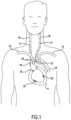
- a front view of a patient is shown in which emboli 18 are transferred from the aortic arch 12 into the carotid arteries 16.
- the emboli 17 that are present in the carotid arteries 16 can then be transferred into the cerebral circulation causing stroke of the patient.
- the emboli 18 may be fragments of atherosclerotic plaque 29 of the aorta 12 that become dislodged during manipulation of the ascending thoracic aorta 12.
- calcification of the aortic valve 15 and intracardiac emboli 20 of the heart 11 that can also be the origin of emboli 17 eventually present in the carotid artery 16.
- the intracardiac emboli 20 may include air, gas, thrombi and atherosclerotic materials. Although all of the various emboli in the heart 11, aortic arch 12 and aortic valve 15 need not be present in all instances, they are all shown in Fig. 1 for sake of example.
- Critical moments of the aforementioned procedures may cause emboli 17 to form and cause stroke and are referred to as "emboligenic" events.
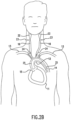
- Figs. 2A and 2B show the disclosed method of diverging emboli 18 from cerebral circulation by exerting external compression to form areas of compression 23 at the carotid arteries 16 to lead to temporary interruption of carotid flow.
- the distal carotid arteries 22 are present downstream from the areas of compression 23, and the proximal carotid arteries are the portions of carotid arteries 16 upstream from the areas of compression 23.
- a relative pressure gradient and a "no-flow" condition is produced in the proximal carotid arteries 24 that prevents emboli 18 from entering the cerebral circulation.
- the proximal carotid arteries 24 are areas of the carotid arteries 16 upstream from the areas of compression 23 that have interrupted blood flow due to the compression.
- Potential carotid emboli 17 are diverted into the descending aorta 14 and are illustrated as emboli 21.
- the arrow 25 shows preferential direction of the blood flow that carries potential cerebral emboli 17 into the descending aorta 14 when the areas of compression 23 are created.
- Figs. 3A-3D disclose an exemplary embodiment of a device 26 that can be used to create the areas of compression 23 previously described to deflect emboli 17 from the carotid arteries 16 to prevent emboli in the cerebral circulation.
- the device 26 can be positioned on the neck of the patient so that a pair of straps 33 and 43 extend around to the back of the neck of the patient and are secured to one another via hooks 44 and loops 45 that form a hook and loop type arrangement.
- hooks 44 and loops 45 that form a hook and loop type arrangement.
- Securement of the hooks 44 and loops 45 causes the device 26 to be retained onto the neck of the patient.
- the device 26 may be a neck collar in accordance with various exemplary embodiments. In other arrangements the device 26 may be a strap that lays on the front of the neck of the patient, or may be made of multiple components that are not directly attached to one another but are positioned proximate to the neck of the patient.
- the device 26 may include two semi-oval halves that may be positioned around the neck of the patient in accordance with one exemplary embodiment.
- the device 26 need not be circular in shape. Even if the device 26 is not circular in shape it may still have a central axis 56 as the central axis 56 can be located at the center of the neck of the patient and thus may still be a central axis 56 of the device 26.
- a pair of insertion pockets 41 and 42 are present on the device 26 and may be sealed at their tops and bottoms with respect to the vertical direction 55.
- the vertical direction 55 may be the direction of the device 26 that is parallel to the direction of extension of the central axis 56.
- Strap 33 may extend from the first insertion pocket 41, and strap 43 may extend from the second insertion pocket 42.
- the first insertion pocket 41 forms a cavity into which a first longitudinal carotid expandable member 27 is located.
- Member 27 is shown in a deflated or unactuated state in Fig. 3B and may be made of a flexible material that can be stretched or otherwise deformed.
- the material making up member 27 can be nonporous such that member 27 is capable of being filled with gas or liquid that enables the member 27 to expand and at the same time hold the gas or liquid therein.
- the pocket 41 may be made of a material that is different than the material making up member 27.
- the second insertion pocket 42 forms a cavity into which the second longitudinal carotid expandable member 46 is retained.
- Member 46 may be configured in a manner similar to member 27 and a repeat of this information is not necessary.
- Member 46 may be completely sealed except for an opening that leads into connecting tube 54.
- Member 46 is in an unactuated state in Fig. 3B .
- a pressure source 49 is included and is placed into fluid communication with the first longitudinal carotid expandable member 27 by way of pressure tubing 29 that extends through a port of member 27.
- a manometer 30 may be included in the device 26 at some point between the member 27 and the pressure source 49 in order to monitor and measure pressure in the system.
- Figs. 3C and 3D illustrate the device 26 once the pressure source 49 is activated in order to cause the device 26 to be pressurized.
- the pressure source 49 may be a pump that injects air, gas or liquid, such as water, through the pressure tubing 29. Injection of air or otherwise increasing the pressure causes the first longitudinal carotid expandable member 27 to expand.
- the second longitudinal carotid expandable member 46 will likewise expand and the two members 27 and 46 may expand at the same rate to the same size. Expansion may be in the radial direction 57 such that the expandable members 27 and 46 expand towards the central axis 56 and away from the central axis 56. In some exemplary embodiments, the members 27 and 46 may expand in the radial direction 57 towards the central axis 56 but not in the radial direction 57 away from the central axis 56. This arrangement may be accomplished by making portions of the expandable members 27 and 46, for example the portions facing away from the central axis 56 in the radial direction 57, such that they cannot expand while the portion facing towards the central axis 56 are in fact expandable. The expandable members 27 and 46 may be inflated to a pressure level that is above the level of the patient's arterial pressure to achieve temporary interruption of the carotid blood flow. Both the left and right carotid arteries 16 can be compressed at the same time.
- the insertion pockets 41 and 42 could have portions that are made of different materials so that the parts facing the central axis 56 in the radial direction 57 are expandable while the parts facing away from the central axis 56 in the radial direction 57 are not expandable.
- the expandable members 27 and 46 are elongated in the vertical direction 55, which is the same direction as the central axis 56. However, it may be the case that upon expansion of the expandable members 27 and 46 from the unactuated to the actuated states the expandable members 27 and 46 do not expand in the vertical direction 55.
- the exemplary embodiment of the device 26 in Figs. 3A-3D does not include a transverse carotid expandable member 32 but instead includes only two expandable members 46.
- the device 26 may be placed onto the patient so that the first longitudinal carotid expandable member 27 overlays the carotid artery 16 such that the carotid artery 16 is located between the central axis 56 and the member 27 in the radial direction 57.
- the second longitudinal carotid expandable member 46 may be laid on top of the other carotid artery 16 such that the second carotid artery 16 is likewise between the member 46 and the central axis 56 in the radial direction 57.
- Expansion forces of the expandable members 27 and 46 may be imparted onto the carotid arteries 16 so that they are compressed thus forming the areas of compression 23 as previously discussed.
- the pressure in the expandable members 27 and 46 may be set so as to exceed the patient's systemic pressure to achieve adequate compression of the carotid arteries 16 to have a transient "no-flow" effect.
- the pressure of the members 27, 32 and/or 46 may exceed the patient's systemic pressure by 10-20 mm Hg, or up to 30 mm Hg or higher in accordance with certain exemplary embodiments.
- the device 26 in this exemplary embodiment also functions to compress the carotid arteries 16 to create the areas of compression 23.
- the device 26 includes a first insertion pocket 41 and a second insertion pocket 42 but lacks first and second longitudinal carotid expandable members 27 and 46. Instead a first compression member 52 is located within the first insertion pocket 41, and a second compression member 53 is located within the second insertion pocket 42.
- the compression members 52 and 53 are not expandable but may be made of a material, such as foam, that can be compressed and then can subsequently expand back into its original shape.
- the compression members 52 and 53 may alternatively be made of a material that does not exhibit any give upon the application of forces thereto that would be encountered in a procedure of the type described herein.
- the compression members 52 and 53 may be elongated in the vertical direction 55 and may have a convex shape that faces the central axis 56.
- the shape of the compression members 52 and 53 at their surfaces that face away from the central axis 56 in the radial direction 57 may be different than those that face towards the central axis 56.
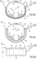
- the device 26 may include a transverse carotid compression section 31 that is located outward from the compression members 52 and 53 in the radial direction 57 from the central axis 56.
- a transverse carotid expandable member 32 may be held by the section 31 and can have an arc length about the central axis 56 that extends beyond both of the compression members 52 and 53.
- the transverse carotid expandable member 32 has a height in the vertical direction 55 that is the same as, larger or smaller than the height of the compression members 52 and 53 in the vertical direction 55.
- the member 32 is made of a material that will hold air, gas or liquid such that it can be expanded upon the application of fluid thereto.
- the member 32 has a single port that is in fluid communication with the pressure tubing 29.
- the member 32 will cause the member 32 to expand as shown for example in Figs. 4C and 4D .
- the compression members 52 and 53 can be removed and not present so that only the expandable member 32 is present to compress the carotid arteries 16.
- the transverse carotid compression section 31 can be arranged so that all of it is expandable or so that only a portion of it expands as the member 32 expands.
- Boundary lines 50 and 51 may demarcate areas of the transverse carotid compression section 31 that can expand from those that cannot expand.
- the portion of section 31 radially outward from the boundary lines 50 and 51 may not be capable of expansion while the portions of section 31 radially inward from boundary lines 50 and 51 are capable of stretching and thus expanding or contracting.
- This arrangement may cause expansion only, or primarily, in the radially inward direction upon expansion of the expandable member 32.
- the section 31 is made of the same material and exhibits expansibility such that it generally expands in all directions equally.
- the expandable member 32 may be arranged so that it does not lengthen in the vertical direction 55 upon expansion, or in some arrangements only minimally expands in the vertical direction 55 when actuated.
- Placement of the device 26 onto the patient may result in the first compression member 52 overlaying the carotid artery 16 so that the carotid artery 16 is between compression member 52 and the central axis 56 in the radial direction 57.
- the second compression member 52 will be arranged so that it overlays the second carotid artery 16 causing it to be between the second compression member 52 and the central axis 56 in the radial direction 57.
- the expandable members 27, 32 and 46 may be located at the neck of the patient such that they are secured to the neck or otherwise proximate the neck. The expandable members 27, 32 and 46 need not be in direct contact with the neck of the patient but only located near the neck of the patient.
- first and second longitudinal carotid expandable members 27 and 46 an alternative arrangement may be made in which these members 27 and 46 are present.
- the expandable members 27 and 46 may expand in order to press the compression members 52 and 53 towards the carotid arteries 16.
- FIG. 5 An alternative exemplary embodiment of the device 26 is illustrated with reference to Fig. 5 in which both a pair of longitudinal carotid expandable members 27 and 46 are present along with a transverse carotid expandable member 32.
- a pair of compression members 52 and 53 may be missing from this embodiment, or they may be present in certain arrangements.
- This exemplary embodiment includes additional pressure tube lines 47 and 48 that are separate from pressure tubing 29 that actuates the transverse carotid expandable member 32.
- Pressure tube lines 47 and 48 provide pressure to the first and second longitudinal carotid expandable members 27 and 46 so that these members 27 and 46 can be expanded at different rates, amounts, and/or times than expandable member 32.
- This flexibility provides selective pressure adjustments between the transverse carotid expandable member 32 and the pair of longitudinal carotid expandable members 27 and 46. This feature will provide an option to decrease or completely eliminate the degree of circumferential neck compression when selective inflation of the two longitudinal carotid expandable members 27 and 46 is adequate. Conversely, if inflation of members 27 and 46 does not lead to sufficient reduction of the carotid flow, an additional inflation of the expandable member 32 would allow one to achieve the desired effect by combining the effect of pressure created in all of the members 27, 46 and 32.
- the preferred method of carotid artery 16 compression in this case will be an initial inflation of members 27 and 46, followed by inflation of member 32 when necessary.
- the degree of interruption of the carotid flow in this and other embodiments can be checked by the data of carotid Doppler, trans-cranial Doppler, pulsation of the temporal arteries and other techniques of assessment of the carotid and cerebral perfusion.
- the other components of the device 26 are the same as those previously disclosed with respect to other embodiments and a repeat of this information is not necessary.
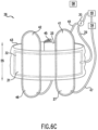
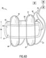
- FIG. 6A-6D An alternative exemplary embodiment of the device 26 is disclosed with reference to Figs. 6A-6D .
- the embodiment disclosed is similar to that previously disclosed with respect to Fig. 5 and a repeat of the features and functionality that are similar between the two need not be repeated.
- the pressurization of the members 27, 32 and 46 are different in that the second pressure tube 47 feeds into the first longitudinal carotid expandable member 27, and in that the third pressure tube 48 supplies the second longitudinal carotid expandable member 46 to allow the members 27 and 46 to be pressurized independently from one another.
- one can apply more or less pressure to member 27 than member 46 so that compression of the carotid arteries 16 can be more precisely controlled.
- the transverse carotid expandable member 32 is supplied by pressure tubing 29 and is independent from the expansion of members 27 and 46 such that it can be pressurized to a greater or lesser extent than members 27 and 46.
- the manometer 30 may be capable of measuring pressures in all of the lines 29, 47 and 48 so that their individual pressures can be monitored. In use, one may adjust the pressures in members 27 and 46 first, then subsequently if needed one may apply pressure into member 32 to cause its expansion so that adequate compression of the carotid arteries 16 is realized.
- the ports for the pressure lines 47 and 48 may be located at the bottom of the expandable members 27 and 46 in the vertical direction 55. However, the ports for pressure lines 47 and 48 need not be in the disclosed locations in accordance with other exemplary embodiments and may be above the transverse carotid compression section 31 or at the same location as the section 31 in the vertical direction 55 in other exemplary embodiments.
- the insertion pockets 41 and 42 although described as being sealed may have an opening into which the expandable members 27 and 46 may be removed and into which first and/or second compression members 52 and 53 may be inserted so that the device 26 can function with the compression members 52 and 53 and transverse carotid expandable member 32 as previously discussed.
- the arrangement of the device 26 in Figs. 6A-6D thus includes a pair of longitudinal carotid expandable members 27 and 46 along with a transverse carotid expandable member 32.
- the boundary lines 50 and 51 may be located at the boundaries of the straps 33 and 43 and the transverse carotid compression section 31.
- the lengths of the members 27 and 46 in the vertical direction 55 are each longer than the length of the member 32 in the vertical direction 55, and the arc length of the member 32 is larger than the arc lengths of the members 27 and 46 combined.
- the transverse carotid expandable member 32 may have an arc length that extends up to 65% of the circumferential distance about the central axis 56.
- the member 32 may have an arc length that is up to 234 degrees about central axis 56.
- the circumferential distance about the central axis 56 may also be the circumferential distance about the neck of the patient when the device 26 is worn by a patient and thus these two terms can be interchangeable when discussing the arc length of the member 32.
- the arc length of the member 32 may be from 50-65% (180 degrees - 234 degrees) about the circumference of the neck of the patient, from 25%-50% (90 degrees - 180 degrees) about the circumference of the neck of the patient, or from 15%-25% (54 degrees - 90 degrees) about the circumference of the neck of the patient.
- the member 32 may extend 360 degrees completely about the central axis 56/neck of the patient.
- the members 27 and 46 are closer to the central axis 56 in the radial direction 57 than the member 32 is to the central axis 56.
- Comparison of Figs. 6C and 6D demonstrate that the lengths of the members 27, 32 and 46 do not increase in the vertical direction 55, or in the arc length direction, upon moving from the unactuated orientation to the actuated orientation or only slightly expand in these directions upon actuation. The majority of the expansion may be in the radial direction 57 either towards the central axis 56 or away from the central axis 56 or a combination of the two. In other arrangements, however, expansion of the members 27, 32 and 46 may result in equal expansion in all directions.
- various components of the device 26 in Figs. 6A-6D may be arranged and function in a manner similar to those as previously discussed and a repeat of this information is not necessary.
- Figs 7A and 7B disclose modifications of the geometry of the members 27 and 46 with respect to the geometry of the transverse carotid expandable member 32 which is the same in both Figs. 7A and 7B .
- the different geometries for members 27 and 46 may be due to variations of neck anatomy in each patient. In patients with a short and large neck the embodiment in Fig. 7A may be employed that has longitudinal carotid expandable members 27 and 46 that are bigger and more round to achieve more efficient carotid compression.
- the length of each one of the members 27 and 46 in the vertical direction 55 may be less than the length of the member 32 in the vertical direction 55 both when all of the members 27, 32 and 46 are unexpanded, and when all of the members 27, 32 and 46 are expanded.
- the preferred embodiment comprises the members 27 and 46, as shown in Fig. 7B , that are more oval and narrow for the same reason of more efficient carotid compression to account for the differences in neck geometries of patients.
- the lengths of each of the members 27 and 46 in the vertical direction 55 is longer than the length of the member 32 in the vertical direction 55 both when all of the components 27, 32 and 46 are unactuated and when they are all actuated.
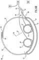
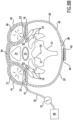
- Figs. 8A and 8B demonstrate the method of use and the effect of inflation of the device 26 resulting in external compression of both carotid arteries 16, leading to transient interruption of carotid flow.
- These two figures demonstrate the anatomic relationship of the device 26 to both carotid arteries 16 and surrounding structures 34, 35, 36, 37 and 40.
- the carotid arteries 16 are bordered by neck muscles 36, esophagus 35, trachea 34 and fat tissues 40. These structures provide a protective cushion, minimizing the risk of carotid injury during external compression.
- carotid arteries 16 in this setting would lead to significantly lower risk of injury to carotid intima than intravascular carotid occlusion with the balloon or umbrella devices used for cerebral protection in patients undergoing carotid stenting.
- the longitudinal carotid expandable members 27, 46 are positioned along the course of both carotid arteries 16 on the neck.
- the exemplary embodiment of the device 26 may be any one of those previously disclosed that lacks a transverse carotid expandable member 32. However, it is to be understood that this is just one example and that other devices 26 that include member 32 can function in a similar manner to the device 26 disclosed in Figs. 8A and 8B . As shown in Fig. 8A , one of the longitudinal carotid expandable members 27 is placed along the course of one of the carotid arteries 16, and the other expandable member 46 is placed along the course of the other carotid artery 16.
- the lumen of both carotid arteries is compressed between the inflated bladders 27 and 46 anteriorly (outward in the radial direction 57) and the cervical spine 37 posteriorly (inward in the radial direction 57). Actuation of the members 27 and 46 cause the members to move radially inward and compress fat tissue 40 that is immediately adjacent the device 26.
- the expandable members 27 and 46 are shown moving in the radial direction 57 inward of portions of the trachea 34 and neck muscles 36 so that portions of the expandable members 27 and 46 are closer to the central axis 56 in the radial direction 57 than portions of the trachea 34 and neck muscles 36.
- Full expansion of the expandable members 27 and 46 may result in inward radial movement so that they are not radially closer to the axis 56 than any portion of the esophagus 35.
- other embodiments are possible in which at least some portion of the expandable members 27 and 46 are closer to the central axis 56 than a portion of the esophagus 35.
- the soft tissues such as the fat tissues 40, neck muscles 36, esophagus 35 and trachea 34 around carotid arteries 16 provide a smooth cushion assuring adequate protection against carotid trauma. Expansion of the members 27 and 46 causes the areas of compression 23 to restrict blood flow through the carotid arteries 16 which leads to transient interruption of carotid flow.
- the trachea 34 and esophagus 35 are not closed or restricted upon actuation of the expandable members 27 and 46 due to the placement and specific configuration of the expandable members 27 and 46. However, in some arrangements some degree of restriction of the trachea 34 and/or esophagus 35 may occur when the expandable members 27 and 46 are expanded.
- carotid Duplex scan it may be advisable, however, to obtain carotid Duplex scan in all patients planned for this procedure to rule out significant atherosclerotic disease of these vessels 16. If the patient is found to have severe carotid disease, the risk of dislodging the carotid plaque due to carotid compression should be weighed against the risk of stroke associated with the main cardiovascular intervention.
- the divergence of potential cerebral emboli 17, 18 and prevention of stroke can be achieved by a noninvasive safe method that involves external compression of the carotid arteries 16.
- the method and device 26 disclosed do not require puncture of the skin or arteries and do not necessitate the use of endovascular devices.
- the device 26 and disclosed method allow for the divergence of emboli 17 and 18 of all sizes, including those microscopic particles that are too small to be trapped with the known intravascular filters.
- the device 26 can be supplied with different carotid compression mechanisms, including different forms of longitudinal bladders, cuffs, compression pads or inserts with the same effect of carotid compression to the point of transient interruption of carotid flow.
- the fluid provided to pressurize the expandable components of the device 26 from the pressure source 49 may be a liquid substance in some embodiments. Fluid that is a liquid may be used in the device 26 to effect pressurization and more uniform constriction of the carotid arteries 16 than gas or air fluid because liquid is more non-compressible at the operating range of pressures. Liquid fluid in the members 27, 32 and 46 may more directly transmit pressure to the carotid area than gas or air fluid.
- the transverse carotid expandable member 32 may be pressurized by a first pressure source 49 such as a pump, while a second source of pressure 49 is included in the device 26 to provide pressure to the two longitudinal carotid expandable members 27 and 46.
- a first pressure source 49 such as a pump
- a second source of pressure 49 is included in the device 26 to provide pressure to the two longitudinal carotid expandable members 27 and 46.
- a monitoring system 58 may be included with the device 26 to assure a safe, adequate, easily manageable and controllable compression of carotid vessels 16.
- the monitoring system 58 may comprise Doppler ultrasound, Doppler probe, oscillotonometry, electroencephalography, transcranial Doppler, cerebral oximetry and/or other techniques.
- the device 26 may be actuated to such a degree that the two areas of compression 23 formed completely stop the flow of blood into the distal carotid artery 22, or to an extent that partial flow of blood passes through the areas of compression 23 and into the distal carotid artery 22 and cerebral circulation.
- the device 26 provided is a noninvasive and precise apparatus with an option of assessing a degree and an effectiveness of an interruption of the carotid flow by the optional inclusion of a monitoring system 58.
- the device 26 assures a uniform and reproducible interruption of the carotid flow bilaterally minimizing the risk of trauma to the carotid artery wall and subsequent cerebral emboli 17.
- alarm system 59 is included in the device 26 that is triggered by excessive or lengthy compression of the carotid arteries 16.
- the alarm system 59 may be a part of the monitoring system 58 or may be a different component that is not part of the monitoring system 58. The alarm system 59 thus measures
- the device 26 provides a noninvasive compression apparatus that does not require the insertion of intravascular devices.
- the device 26 lacks an expandable member 27, 32, or 46 and includes a compression member 52.
- the particular arrangement of Fig. 9 also includes a second compression member 53.
- the compression members 52, 53 are located within and held by first and second insertion pockets 41 and 42.
- the compression members 52 and 53 may be as previously described and a repeat of this information is not necessary.
- the compression members 52, 53 may be referred to as compression members because they function to compress the carotid arteries 16.
- the compression members 52, 53 may themselves be compressible such that they can be deformed when force is applied thereto to be compressed and hence smaller. When the force is removed the compression members 52, 53 can spring back to their non-compressed state.
- the compression members 52, 53 are not compressible themselves at all and maintain the same size and shape when force is applied.
- the compression members 52, 53 still function to compress the carotid arteries 16 even when they themselves are not compressible.
- the compression members 52, 53 function without being expanded by the pressure source 49.
- the device 26 of Fig. 9 lacks a pressure source 49 and no components of the device 26 are expandable.
- a strap 33 extends from the boundary line 50 and has hooks 44 disposed thereon.
- Strap 43 extends from boundary line 51 and has loops 45 located on one surface thereof.
- the straps 33, 43 extend circumferentially around the central axis 56 and may surround the central axis 56 up to 240 degrees in some exemplary embodiments.
- the straps 33, 43 are adjustable in that they can be unattached from one another and then reengaged such that the points of contact between the hooks 44 and the loops 45 are changed. This change causes the relative size of the device 26 in the radial direction 57 to either increase to relive pressure on the neck of the patient, or decrease to increase the amount of pressure on the neck of the patient so that the compression members 52 and 53 apply greater pressure to the carotid arteries 16.
- strap is broad enough to include a pair of straps, a single strap, or any other tightening mechanism. If a single strap is present it will extend from boundary line 50 to boundary line 51 and can be adjustable to increase pressure supplied by the device 26 to the neck of the patient, or non-adjustable such that it may function to hold the device 26 to the neck of the patient while some other mechanism functions to apply pressure to the compression members 52 and 53.
- the device 26 includes a pair of compression members 52, 53 that are held by pockets 41 and 42.
- the compression members 52, 53 may apply pressure to the carotid arteries 16 and in this regard need to directly contact the skin of the neck of the patient. Instead, the insertion pockets 41 and 42 directly contact the skin of the neck of the patient, and the compression members 52, 53 apply pressure to the carotid arteries 16 by exerting force through the insertion pockets 41, 42 and into the neck of the patient.
- the embodiment in Figs. 10A and 10B lacks a source of pressure and the device 26 does not have an expandable member.
- Strap 33 extends from boundary line 50 of the device 26 and is longer than strap 43 that extends from boundary line 51.
- a lock and adjustment clip 60 is attached to the end of strap 33 and this attachment may be a permanent attachment.
- Strap 43 is not attached to the lock and adjustment clip 60 in Fig. 10A .
- the health care provider may place the device 26 around the neck of the patient so that the compression members 52, 53 overlay the carotid arteries 16 of the patient.
- the strap 43 could be moved through the lock and adjustment clip 60 and secured thereto so that the strap 43 is attached to the strap 33 to cause the device to be held onto the neck of the patient.
- the tightening of the strap 43 relative to strap 33 may be loose such that the compression members 52, 53 do not apply pressure to the carotid arteries 16.
- the health care provider may adjust the strap 43 relative to the lock and adjustment clip 60 as shown for instance in Fig. 10B .
- the health care provider can move a desired amount of the length of strap 43 through the lock and adjustment clip 60 and then lock the strap 43 to the lock and adjustment clip 60 so that it does not move relative thereto.
- This adjustment causes the size of the device 26 in the radial direction 57 to decrease, relative to the size in Fig. 10A , and forces the compression members 52, 53 against the carotid arteries 16 to compress the carotid arteries 16.
- the straps 33, 43 thus function to not only hold the device 26 onto the neck of the patient, but to also apply the pressure necessary for compressing the carotid arteries 16.
- the straps 33 and 43 can be located on the device 26 to hold the device 26 onto the patient but not to provide force that causes the compression members 52, 53 to be pressed against the carotid arteries 16.
- the device 26 may lack any members that are expandable, and thus may lack a pressure source 49.
- a belt or other mechanism can be wrapped around the compression members 52, 53 and may be tightened so that force from this tightening is transferred to the compression members 52, 53 so that they in turn will be urged against the carotid arteries 16 to close the carotid arteries 16.
- a method for reducing or totally preventing cerebral emboli will now be discussed.
- a brief compression of carotid arteries 16 by way of a device 26 may be performed first to assure adequate position of the device leading to reduction or interruption of carotid flow or pulse as assessed by carotid Doppler, a pressure gauge, percutaneous cerebral oximetry or transcranial Doppler.
- the pressure in the carotid compression components (27, 32 and 46) is released and the apparatus 26 is ready for use.
- the device 26 is inflated to the pressure exceeding patient's systemic pressure just before proceeding with the emboligenic part of the procedure. Adequate compression of carotid arteries 16 will lead to physiological reduction of flow through vertebral arteries leading to further divergence of blood and emboli away from all cerebral vessels and toward more distal arteries, thus decreasing the risk of stroke.
- the pressure in the device 26, and thus to the expandable components 27, 32 and 46 is released after the emboligenic procedure is completed after a full washout of potential emboli 20, 18 from the heart 11 and thoracic aorta 12.
- the pressurization of the device 26 can be repeated any time and on multiple occasions when the emboligenic intervention is contemplated.
- an alarm would go off and the pressure would be released spontaneously to avoid undue interruption of the cerebral flow.
- the alarm and deflation can be overridden by the physician when clinically indicated.
- the alarm may be sounded by the alarm system 59, and the deflation is activated by the pressure source 49 and/or the alarm system 59 According to an example not forming part of the invention, the deflation can be activated by the monitoring system 58.
- the central axis 56 may be present even when the device 26 is not configured with straps 33, 43 to form a generally circular member when viewed from the top as for example in Fig. 6A .
- a circular member is not formed when viewed from the top by the straps 33, 43.
- the straps 33, 43 may be missing such that the section 31 is attached to sides of a bed or otherwise secured so that the device 26 is located at the neck of the patient.
- the central axis 56 is still present.
- the central axis 56 may be located at a location within the neck of the patient, for examples shown with reference to Figs. 8A and 8B .
- This location may be at the spinal column 37 of the patient, or may be at the center of the neck of the patient. It is to be understood that various embodiments of the device 26 exist in which the device 26 does not wrap completely around the neck of the patient but instead only wraps around a portion of the neck of the patient less than 360 degrees fully about the neck of the patient.
- the device 26 may be provided so that no portion of the device 26 is inside of the patient and all of the device 26 is located outside of the patient.
- the method may be performed such that nothing is inserted inside of the patient to deflect the emboli 18.
- the device 26 is not an invasive device as no portion is located within the carotid arteries 16 or under the skin or otherwise inside of the patient.
- the device 26 may be arranged so that it contacts the neck of the patient but not other parts of the patient such as the head of the patient, the arm of the patient, the leg of the patient, the chest of the patient, or the back of the patient.
- the device 26 may function to compress the carotid arteries 16 but not any other arteries of the patient. In this regard, the only arteries that are compressed by the device 26 are the carotid arteries 16.
Landscapes
- Health & Medical Sciences (AREA)
- Life Sciences & Earth Sciences (AREA)
- Surgery (AREA)
- Heart & Thoracic Surgery (AREA)
- Molecular Biology (AREA)
- Vascular Medicine (AREA)
- Engineering & Computer Science (AREA)
- Biomedical Technology (AREA)
- Reproductive Health (AREA)
- Medical Informatics (AREA)
- Nuclear Medicine, Radiotherapy & Molecular Imaging (AREA)
- Animal Behavior & Ethology (AREA)
- General Health & Medical Sciences (AREA)
- Public Health (AREA)
- Veterinary Medicine (AREA)
- Biophysics (AREA)
- Hematology (AREA)
- Infusion, Injection, And Reservoir Apparatuses (AREA)
- Surgical Instruments (AREA)
Claims (4)
- Vorrichtung (26) zur Ablenkung von Embolien (17, 18, 20) vom Hirnkreislauf eines Patienten, umfassend:ein Element (27, 31, 46), das angeordnet ist, um auf eine Arteria carotis (16) des Patienten zu drücken, um die Arteria carotis zusammenzudrücken und den Blutfluss durch die Arteria carotis (16) einzuschränken, wobei das Element (27, 32, 46) zum Anlegen um den Hals des Patienten angeordnet ist, wobei das Element ein ausdehnbares Element (27, 32, 46) ist, das angeordnet ist, um sich von einer nicht ausgedehnten Anordnung auf eine ausgedehnte Anordnung auszudehnen, wobei, wenn das ausdehnbare Element (27, 32, 46) sich am Hals eines Patienten befindet und wenn es in der ausgedehnten Anordnung ist, das ausdehnbare Element einen Bereich der Kompression (23) der Arteria carotis (16) des Patienten erzeugt und den Blutfluss durch die Arteria carotis (16) einschränkt und wobei die Vorrichtung ferner eine Druckquelle (49), die angeordnet ist, um Druck auf das ausdehnbare Element (27, 32, 46) anzuwenden, um das ausdehnbare Element von der nicht ausgedehnten Anordnung auf die ausgedehnte Anordnung zu bewegen, und ein Manometer (30), das angeordnet ist, um den von der Druckquelle (49) angewendeten Druck zu messen, aufweist;dadurch gekennzeichnet, dass die Vorrichtung ferner ein Alarmsystem (59) aufweist, das zum Messen einer Kompressionszeit und eines Kompressionsbetrags des ausdehnbaren Elements angeordnet ist, wobei, wenn die Kompression länger als eine vorbestimmte Zeit angewendet wird, das Alarmsystem (59) einen Alarm aktiviert und spontan Druck im ausdehnbaren Element durch die Druckquelle und/oder das Alarmsystem abgelassen wird und wobei der Alarm und das Ablassen von Druck von Hand übersteuert werden können.
- Vorrichtung (26) nach Anspruch 1, wobei die Vorrichtung (26) eine Mittelachse (56) hat und wobei das Element ein längs verlaufendes ausdehnbares Carotiselement (27) ist, das die Arteria carotis (16) des Patienten überlagert und sich näher an der Mittelachse (56) befindet, wenn es in der ausgedehnten Anordnung ist, als wenn es in der nicht ausgedehnten Anordnung ist.
- Vorrichtung (26) nach Anspruch 1, wobei die Vorrichtung (26) eine Mittelachse (56) hat, wobei das Element ein quer verlaufendes ausdehnbares Carotiselement (32) ist, das eine Länge hat, die sich in einer Bogenlänge um die Mittelachse (56) erstreckt, wobei die Bogenlänge länger als eine zur Mittelachse (56) parallele Länge des quer verlaufenden ausdehnbaren Carotiselements (32) ist.
- Vorrichtung (26) nach Anspruch 3, die ferner aufweist:eine erste Einsetztasche (41);ein erstes Kompressionselement (52), das von der ersten Einsetztasche (41) getragen wird, wobei das erste Kompressionselement (52) in einer Radialrichtung (57) näher an der Mittelachse (56) ist als das quer verlaufende ausdehnbare Carotiselement (32), wobei das erste Kompressionselement (52) nicht aufblähbar ist;eine zweite Einsetztasche (42); undein zweites Kompressionselement (53), das von der zweiten Einsetztasche (42) getragen wird, wobei das zweite Kompressionselement (53) in der Radialrichtung (57) näher an der Mittelachse (56) ist als das quer verlaufende ausdehnbare Carotiselement (32), wobei das zweite Kompressionselement (53) nicht aufblähbar ist.
Applications Claiming Priority (2)
| Application Number | Priority Date | Filing Date | Title |
|---|---|---|---|
| US201261646088P | 2012-05-11 | 2012-05-11 | |
| EP13167290.9A EP2662034B1 (de) | 2012-05-11 | 2013-05-10 | Anti-Embolievorrichtung |
Related Parent Applications (1)
| Application Number | Title | Priority Date | Filing Date |
|---|---|---|---|
| EP13167290.9A Division EP2662034B1 (de) | 2012-05-11 | 2013-05-10 | Anti-Embolievorrichtung |
Publications (2)
| Publication Number | Publication Date |
|---|---|
| EP3305218A1 EP3305218A1 (de) | 2018-04-11 |
| EP3305218B1 true EP3305218B1 (de) | 2024-10-09 |
Family
ID=48470732
Family Applications (2)
| Application Number | Title | Priority Date | Filing Date |
|---|---|---|---|
| EP13167290.9A Active EP2662034B1 (de) | 2012-05-11 | 2013-05-10 | Anti-Embolievorrichtung |
| EP17199143.3A Active EP3305218B1 (de) | 2012-05-11 | 2013-05-10 | Anti-embolie-vorrichtung |
Family Applications Before (1)
| Application Number | Title | Priority Date | Filing Date |
|---|---|---|---|
| EP13167290.9A Active EP2662034B1 (de) | 2012-05-11 | 2013-05-10 | Anti-Embolievorrichtung |
Country Status (2)
| Country | Link |
|---|---|
| US (3) | US9655627B2 (de) |
| EP (2) | EP2662034B1 (de) |
Families Citing this family (19)
| Publication number | Priority date | Publication date | Assignee | Title |
|---|---|---|---|---|
| US10842502B2 (en) * | 2009-09-11 | 2020-11-24 | Tbi Innovations, Llc | Devices and systems to mitigate traumatic brain and other injuries caused by concussive or blast forces |
| US10130374B2 (en) | 2012-05-11 | 2018-11-20 | Michael Zhadkevich | Anti-embolic device and method |
| US9655627B2 (en) | 2012-05-11 | 2017-05-23 | Michael Zhadkevich | Anti-embolic device and method |
| US8900169B2 (en) | 2013-03-15 | 2014-12-02 | Tbi Innovations, Llc | Methods and devices to reduce the likelihood of injury from concussive or blast forces |
| EP2796099B1 (de) * | 2013-04-28 | 2017-09-13 | Michael Zhadkevich | Anti-Embolie-Vorrichtung |
| US9332994B2 (en) * | 2013-07-12 | 2016-05-10 | Vasoinnovations, Inc. | Apparatus and method to stop bleeding |
| US20150080942A1 (en) * | 2013-09-13 | 2015-03-19 | Silk Road Medical, Inc. | System and Method for Assisted Manual Compression of Blood Vessel |
| EP3139840B1 (de) * | 2014-05-04 | 2019-11-06 | Michael Zhadkevich | Nichtinvasiver schutz vor emboli |
| EP3050520A1 (de) * | 2015-01-27 | 2016-08-03 | Michael Zhadkevich | Vorrichtungen und verfahren zur vaskulären kompression |
| EP3345555B1 (de) * | 2015-09-03 | 2020-10-21 | Terumo Kabushiki Kaisha | Hämostatisches instrument |
| CN108024818B (zh) * | 2015-09-03 | 2021-07-16 | 泰尔茂株式会社 | 止血器具 |
| JP2018171081A (ja) * | 2015-09-03 | 2018-11-08 | テルモ株式会社 | 止血器具 |
| US11103416B2 (en) | 2015-09-28 | 2021-08-31 | Michael Zhadkevich | Device and method for simultaneous detection, monitoring and prevention of cerebral emboli |
| AU2016355540B2 (en) | 2015-11-16 | 2021-02-18 | Q30 Sports Science, Llc | Traumatic brain injury protection devices |
| EP3422959A4 (de) | 2016-03-02 | 2019-11-27 | Q30 Sports Science, LLC | Verfahren und vorrichtungen zur verringerung der schädlichen wirkungen von erschütterungs- oder sprengkräften auf eine person |
| CN106175866B (zh) * | 2016-08-05 | 2019-03-19 | 南京大学医学院附属鼓楼医院 | 一种颈动脉术区手术切口压迫止血器 |
| US11596417B2 (en) | 2019-02-28 | 2023-03-07 | Terumo Kabushiki Kaisha | Hemostasis band with improved edge design |
| WO2020243825A1 (en) * | 2019-06-06 | 2020-12-10 | Les Entreprises Nanostent Inc. | Method and apparatus for adjustable and simultaneous multiple vessel compression |
| CN113786224B (zh) * | 2021-09-15 | 2024-05-28 | 中国人民解放军海军军医大学第一附属医院 | 用于脑血管疾病介入手术操作的颈动脉压迫器及压迫方法 |
Family Cites Families (86)
| Publication number | Priority date | Publication date | Assignee | Title |
|---|---|---|---|---|
| FR699349A (fr) | 1929-06-27 | 1931-02-13 | Dispositif d'interception totale ou partielle de la circulation dans les vaisseaux sanguins | |
| FR719730A (fr) | 1931-07-08 | 1932-02-09 | Appareil compressif contre le mal de mer | |
| US2271927A (en) | 1938-06-16 | 1942-02-03 | Edward S Saighman | Tourniquet |
| US2676586A (en) | 1942-06-24 | 1954-04-27 | Jr Charles A Coakwell | Blackout-preventing device |
| US2571461A (en) | 1949-12-30 | 1951-10-16 | Walter R Livingston | Tourniquet |
| US3587584A (en) | 1968-12-26 | 1971-06-28 | Orthopedic Equipment Co | Inflatable torniquet |
| US4686085A (en) * | 1980-04-14 | 1987-08-11 | Thomas Jefferson University | Stroke treatment utilizing extravascular circulation of oxygenated synthetic nutrients to treat tissue hypoxic and ischemic disorders |
| DE3242814A1 (de) | 1982-11-19 | 1984-05-24 | Siemens AG, 1000 Berlin und 8000 München | Verfahren und respirator zur beatmung eines patienten im herzrhytmus und zur unterstuetzung der blutzirkulation |
| US4753226A (en) | 1985-04-01 | 1988-06-28 | Biomedical Engineering Development Center of Sun Yat-Sen University of Medical Science | Combination device for a computerized and enhanced type of external counterpulsation and extra-thoracic cardiac massage apparatus |
| US4745924A (en) | 1986-06-30 | 1988-05-24 | Spacelabs, Inc. | Blood pressure cuff |
| US5234459A (en) * | 1989-11-20 | 1993-08-10 | Hans Lee | Method of controlling the flow of blood through a limb |
| EP0462088B1 (de) | 1990-06-11 | 1995-11-08 | Radi Medical Systems Ab | Gerät zur Kompression des Oberschenkels |
| US5741295A (en) | 1991-09-30 | 1998-04-21 | James A. McEwen | Overlapping tourniquet cuff system |
| US5271409A (en) | 1991-11-12 | 1993-12-21 | Spacelabs Medical, Inc. | Non-bunching cinch ring engagement for blood pressure cuff |
| US5514079A (en) | 1992-08-11 | 1996-05-07 | Dillon; Richard S. | Method for promoting circulation of blood |
| US5348015A (en) | 1992-09-17 | 1994-09-20 | Applied Physiology And Medicine | Method and apparatus for ultrasonically detecting, counting and/or characterizing emboli |
| US5376067A (en) * | 1992-10-28 | 1994-12-27 | Daneshvar; Yousef | Pressure bandages and dressings |
| US5312350A (en) | 1992-11-30 | 1994-05-17 | Andrew Jacobs | Vein spotter |
| US5372575A (en) * | 1993-02-16 | 1994-12-13 | Safeguard Industrial Corporation | Therapeutic forearm appliance having pressure pad containing parallel chambers |
| US5441051A (en) | 1995-02-09 | 1995-08-15 | Hileman; Ronald E. | Method and apparatus for the non-invasive detection and classification of emboli |
| US5792173A (en) | 1995-07-10 | 1998-08-11 | Stuart D. Edwards | Wound closure hemostasis device |
| US5989281A (en) | 1995-11-07 | 1999-11-23 | Embol-X, Inc. | Cannula with associated filter and methods of use during cardiac surgery |
| US5685321A (en) | 1996-06-03 | 1997-11-11 | Klingenstein; Ralph James | Device and method to facilitate colonoscopy by externally supporting the colon |
| AU6588398A (en) | 1997-04-14 | 1998-11-11 | Advanced Closure Systems, Inc. | Feedback controlled disposable hemostasis device |
| US6179793B1 (en) | 1998-01-14 | 2001-01-30 | Revivant Corporation | Cardiac assist method using an inflatable vest |
| GB9802588D0 (en) | 1998-02-07 | 1998-04-01 | Fisher Peter | Inflatable collar |
| CA2320956A1 (en) * | 1998-02-13 | 1999-08-19 | Ventrica, Inc. | Methods and devices providing transmyocardial blood flow to the arterial vascular system of the heart |
| US6063036A (en) | 1998-02-19 | 2000-05-16 | Li; Pao-Lang | Portable alarm apparatus for sudden heart attack patient |
| US6336901B1 (en) | 1998-04-27 | 2002-01-08 | Omron Corporation | Sphygmomanometer cuff achieving precise measurement of blood pressure |
| US6238413B1 (en) * | 1998-07-02 | 2001-05-29 | Robert Wexler | Apparatus for applying cranial occipital pressure |
| US6547736B1 (en) | 1998-11-11 | 2003-04-15 | Spentech, Inc. | Doppler ultrasound method and apparatus for monitoring blood flow and detecting emboli |
| US6589267B1 (en) | 2000-11-10 | 2003-07-08 | Vasomedical, Inc. | High efficiency external counterpulsation apparatus and method for controlling same |
| US20060100530A1 (en) * | 2000-11-28 | 2006-05-11 | Allez Physionix Limited | Systems and methods for non-invasive detection and monitoring of cardiac and blood parameters |
| US7331977B2 (en) * | 2001-08-14 | 2008-02-19 | Mcewen James A | Adaptive tourniquet cuff system |
| US7241304B2 (en) | 2001-12-21 | 2007-07-10 | Advanced Cardiovascular Systems, Inc. | Flexible and conformable embolic filtering devices |
| EP1382306B1 (de) * | 2002-07-15 | 2009-07-15 | Terumo Kabushiki Kaisha | Blutstillende Vorrichtung mit aufblasbarem Ballon |
| US8357831B2 (en) * | 2003-02-04 | 2013-01-22 | Buckman Robert F | Surgical packing devices |
| US7244225B2 (en) | 2003-10-07 | 2007-07-17 | Cardiomedics, Inc. | Devices and methods for non-invasively improving blood circulation |
| WO2005051206A1 (en) | 2003-11-21 | 2005-06-09 | Vnus Medical Technologies, Inc. | Method and apparatus for treating a carotid artery |
| EP1718261A4 (de) | 2004-02-04 | 2009-05-20 | Flowmedic Ltd | Verfahren und system für die externe gegenpulsation |
| IL161159A0 (en) * | 2004-03-29 | 2004-08-31 | Cyclo Science Ltd | Tourniquet |
| US7074177B2 (en) | 2004-06-30 | 2006-07-11 | David Anthony Pickett | High-efficiency external counterpulsation apparatus and method for performing the same |
| US8109964B2 (en) * | 2004-09-15 | 2012-02-07 | Payne Richard A | Device for compression of tissue under the eyes |
| US7628756B2 (en) | 2005-03-07 | 2009-12-08 | Terumo Cardiovascular Systems Corporation | Extracorporeal emboli detector |
| US8617074B2 (en) | 2005-08-18 | 2013-12-31 | Stichting Katholieke Universiteit | Method and apparatus for generating hardness and/or strain information of a tissue |
| US7967766B2 (en) * | 2005-10-27 | 2011-06-28 | Sundaram Ravikumar | Compression garment with heel elevation |
| WO2007074350A1 (en) | 2005-12-28 | 2007-07-05 | Andrea Marinello | Device for the treatment of carotid artery diseases |
| US8062324B2 (en) | 2006-05-08 | 2011-11-22 | S.M.T. Research And Development Ltd. | Device and method for vascular filter |
| DE102006024176B4 (de) | 2006-05-23 | 2008-08-28 | Pah, Gunnar M. | Vorrichtung zum Filtern von Blut beim Beseitigen einer Herzklappenstenose und Verfahren zum Beseitigen einer Herzklappenstenose |
| GB0614218D0 (en) * | 2006-07-18 | 2006-08-23 | Uws Ventures Ltd | Device and method for altering cardiac activity |
| US20100324589A1 (en) | 2006-09-11 | 2010-12-23 | Carpenter Judith T | Embolic deflection device |
| TW200826900A (en) | 2006-12-22 | 2008-07-01 | Univ Nat Taiwan | Carotid artery pulse wave measuring device |
| AP2802A (en) | 2007-01-05 | 2013-11-30 | Cytec Tech Corp | Process for the removal of impurities from carbonate minerals |
| US20080262535A1 (en) | 2007-04-06 | 2008-10-23 | Ohk Medical Devices Ltd. | Method and an apparatus for adjusting Blood circulation in a limb |
| WO2008150966A1 (en) | 2007-06-01 | 2008-12-11 | Virginia Commonwealth University | Device for control of difficult to compress hemorrhage |
| US7988104B1 (en) | 2007-10-26 | 2011-08-02 | Flotation Technologies, Inc. | Drilling riser auxiliary clamp with integral mux clamp |
| US20090287101A1 (en) | 2008-05-13 | 2009-11-19 | Searete Llc, A Limited Liability Corporation Of The State Of Delaware | Circulatory monitoring systems and methods |
| US8114117B2 (en) * | 2008-09-30 | 2012-02-14 | Tyco Healthcare Group Lp | Compression device with wear area |
| CN201356600Y (zh) * | 2009-03-02 | 2009-12-09 | 四川大学华西医院 | 颈动脉血流体外智能阻断仪 |
| USD643536S1 (en) | 2009-05-19 | 2011-08-16 | Welch Allyn, Inc. | Blood-pressure cuff |
| WO2010141752A1 (en) | 2009-06-03 | 2010-12-09 | Silk Road Medical, Inc. | System and methods for controlling retrograde carotid arterial blood flow |
| EP2448474B1 (de) | 2009-06-23 | 2019-09-18 | Boris Leschinsky | Vorrichtungen zur ischämischen fern-vorbedingung und nahezu durchgehende blutdrucküberwachung |
| US20110054322A1 (en) | 2009-09-01 | 2011-03-03 | Paolo Zanatta | Microembolic signals detection during cordiopulmonary bypass |
| US9173660B2 (en) | 2009-09-11 | 2015-11-03 | Tbi Innovations, Llc | Methods and devices to reduce the likelihood of injury from concussive or blast forces |
| WO2011088543A1 (en) * | 2010-01-22 | 2011-07-28 | Abatis Medical Technologies Limited | Tourniquet apparatus for controlling blood penetration |
| SG10201908576VA (en) * | 2010-04-08 | 2019-10-30 | Hospital For Sick Children | Use of remote ischemic conditioning for traumatic injury |
| US20120035652A1 (en) * | 2010-08-05 | 2012-02-09 | Mcgrimley William A | Sciatic Relief Device |
| EP2605697A1 (de) | 2010-08-18 | 2013-06-26 | Sasi Solomon | Vorrichtung und vefahren zur erkennung eines sich in einem blutgefäss bewegenden embolus |
| US20120150215A1 (en) | 2010-12-09 | 2012-06-14 | Juarez Industries | Junctional Bleed Device |
| US20120232578A1 (en) * | 2011-02-11 | 2012-09-13 | Deka Products Limited Partnership | Apparatus and methods for controlling bleeding using externally applied pressure |
| US8449565B2 (en) | 2011-07-21 | 2013-05-28 | Francis Duhay | Approaches to venous occlusion for embolus management |
| JPWO2013108592A1 (ja) | 2012-01-19 | 2015-05-11 | コニカミノルタ株式会社 | 超音波診断装置および超音波診断装置の制御方法 |
| US9655627B2 (en) | 2012-05-11 | 2017-05-23 | Michael Zhadkevich | Anti-embolic device and method |
| US10130374B2 (en) | 2012-05-11 | 2018-11-20 | Michael Zhadkevich | Anti-embolic device and method |
| WO2014037960A1 (en) | 2012-07-10 | 2014-03-13 | Potdar Anil | Vascular puncture site closure device |
| WO2014027347A1 (en) | 2012-08-13 | 2014-02-20 | Mor Research Applications Ltd. | Radial artery device |
| US20140081098A1 (en) | 2012-09-14 | 2014-03-20 | Nellcor Puritan Bennett Llc | Sensor system |
| CA2890157A1 (en) | 2012-10-31 | 2014-05-08 | Pennypacker CARL | Novel system for emboli detection in the brain using a transcranial doppler photoacoustic device capable of vasculature and perfusion measurement |
| US9414752B2 (en) | 2012-11-09 | 2016-08-16 | Elwha Llc | Embolism deflector |
| US20140194740A1 (en) | 2013-01-07 | 2014-07-10 | Cerebrosonics, Llc | Emboli detection in the brain using a transcranial doppler photoacoustic device capable of vasculature and perfusion measurement |
| EP2796099B1 (de) | 2013-04-28 | 2017-09-13 | Michael Zhadkevich | Anti-Embolie-Vorrichtung |
| US9427239B2 (en) | 2013-07-12 | 2016-08-30 | Semier Technologies, Inc. | Apparatus and method of use for an adjustable radial and ulnar compression wristband |
| US20150080942A1 (en) | 2013-09-13 | 2015-03-19 | Silk Road Medical, Inc. | System and Method for Assisted Manual Compression of Blood Vessel |
| US20160030001A1 (en) | 2014-03-31 | 2016-02-04 | Stuart Stein | Helmet Apparatus and System with Carotid Collar Means On-Boarded |
| EP3139840B1 (de) | 2014-05-04 | 2019-11-06 | Michael Zhadkevich | Nichtinvasiver schutz vor emboli |
| US20160317370A1 (en) | 2015-05-01 | 2016-11-03 | 1834958 Alberta Inc. | Cushion with bladders running different pressurization modes inside and outside dynamically selected target bladder group |
-
2013
- 2013-04-09 US US13/859,235 patent/US9655627B2/en active Active
- 2013-05-10 EP EP13167290.9A patent/EP2662034B1/de active Active
- 2013-05-10 EP EP17199143.3A patent/EP3305218B1/de active Active
-
2017
- 2017-04-13 US US15/486,560 patent/US11116515B2/en active Active
-
2021
- 2021-08-16 US US17/402,799 patent/US11701126B2/en active Active
Also Published As
| Publication number | Publication date |
|---|---|
| US9655627B2 (en) | 2017-05-23 |
| EP2662034B1 (de) | 2017-11-01 |
| US20220022888A1 (en) | 2022-01-27 |
| EP2662034A1 (de) | 2013-11-13 |
| US11116515B2 (en) | 2021-09-14 |
| US20170231641A1 (en) | 2017-08-17 |
| EP3305218A1 (de) | 2018-04-11 |
| US20130304111A1 (en) | 2013-11-14 |
| US11701126B2 (en) | 2023-07-18 |
Similar Documents
| Publication | Publication Date | Title |
|---|---|---|
| US11701126B2 (en) | Anti-embolic device and method | |
| US11116517B2 (en) | Anti-embolic device and method | |
| US10765841B2 (en) | Occluding catheter and dynamic method for prevention of stroke | |
| JP6472536B2 (ja) | 低プロファイル閉塞バルーンカテーテル用のシステムおよび方法 | |
| US10667825B2 (en) | Noninvasive protection from emboli | |
| CA2020981C (en) | Tourniquet apparatus for intravenous regional anesthesia | |
| US10813648B2 (en) | Systems and methods for effecting the total and partial occlusion of the aorta of a living being | |
| EP2796099B1 (de) | Anti-Embolie-Vorrichtung | |
| US10219807B2 (en) | Occluding catheter for prevention of stroke | |
| US11103416B2 (en) | Device and method for simultaneous detection, monitoring and prevention of cerebral emboli | |
| JP2019048059A (ja) | 低プロファイル閉塞バルーンカテーテル用のシステムおよび方法 | |
| US11759212B2 (en) | Devices and techniques for vascular compression |
Legal Events
| Date | Code | Title | Description |
|---|---|---|---|
| PUAI | Public reference made under article 153(3) epc to a published international application that has entered the european phase |
Free format text: ORIGINAL CODE: 0009012 |
|
| STAA | Information on the status of an ep patent application or granted ep patent |
Free format text: STATUS: THE APPLICATION HAS BEEN PUBLISHED |
|
| AC | Divisional application: reference to earlier application |
Ref document number: 2662034 Country of ref document: EP Kind code of ref document: P |
|
| AK | Designated contracting states |
Kind code of ref document: A1 Designated state(s): AL AT BE BG CH CY CZ DE DK EE ES FI FR GB GR HR HU IE IS IT LI LT LU LV MC MK MT NL NO PL PT RO RS SE SI SK SM TR |
|
| STAA | Information on the status of an ep patent application or granted ep patent |
Free format text: STATUS: REQUEST FOR EXAMINATION WAS MADE |
|
| 17P | Request for examination filed |
Effective date: 20181010 |
|
| RBV | Designated contracting states (corrected) |
Designated state(s): AL AT BE BG CH CY CZ DE DK EE ES FI FR GB GR HR HU IE IS IT LI LT LU LV MC MK MT NL NO PL PT RO RS SE SI SK SM TR |
|
| STAA | Information on the status of an ep patent application or granted ep patent |
Free format text: STATUS: EXAMINATION IS IN PROGRESS |
|
| 17Q | First examination report despatched |
Effective date: 20200211 |
|
| RAP3 | Party data changed (applicant data changed or rights of an application transferred) |
Owner name: ZHADKEVICH, MICHAEL |
|
| RIN1 | Information on inventor provided before grant (corrected) |
Inventor name: ZHADKEVICH, MICHAEL |
|
| GRAP | Despatch of communication of intention to grant a patent |
Free format text: ORIGINAL CODE: EPIDOSNIGR1 |
|
| STAA | Information on the status of an ep patent application or granted ep patent |
Free format text: STATUS: GRANT OF PATENT IS INTENDED |
|
| INTG | Intention to grant announced |
Effective date: 20240516 |
|
| GRAS | Grant fee paid |
Free format text: ORIGINAL CODE: EPIDOSNIGR3 |
|
| P01 | Opt-out of the competence of the unified patent court (upc) registered |
Free format text: CASE NUMBER: APP_43592/2024 Effective date: 20240725 |
|
| GRAA | (expected) grant |
Free format text: ORIGINAL CODE: 0009210 |
|
| STAA | Information on the status of an ep patent application or granted ep patent |
Free format text: STATUS: THE PATENT HAS BEEN GRANTED |
|
| AC | Divisional application: reference to earlier application |
Ref document number: 2662034 Country of ref document: EP Kind code of ref document: P |
|
| AK | Designated contracting states |
Kind code of ref document: B1 Designated state(s): AL AT BE BG CH CY CZ DE DK EE ES FI FR GB GR HR HU IE IS IT LI LT LU LV MC MK MT NL NO PL PT RO RS SE SI SK SM TR |
|
| REG | Reference to a national code |
Ref country code: CH Ref legal event code: EP |
|
| REG | Reference to a national code |
Ref country code: DE Ref legal event code: R096 Ref document number: 602013086178 Country of ref document: DE |
|
| REG | Reference to a national code |
Ref country code: IE Ref legal event code: FG4D |
|
| REG | Reference to a national code |
Ref country code: LT Ref legal event code: MG9D |
|
| REG | Reference to a national code |
Ref country code: NL Ref legal event code: MP Effective date: 20241009 |
|
| REG | Reference to a national code |
Ref country code: AT Ref legal event code: MK05 Ref document number: 1729692 Country of ref document: AT Kind code of ref document: T Effective date: 20241009 |
|
| PG25 | Lapsed in a contracting state [announced via postgrant information from national office to epo] |
Ref country code: NL Free format text: LAPSE BECAUSE OF FAILURE TO SUBMIT A TRANSLATION OF THE DESCRIPTION OR TO PAY THE FEE WITHIN THE PRESCRIBED TIME-LIMIT Effective date: 20241009 |
|
| PG25 | Lapsed in a contracting state [announced via postgrant information from national office to epo] |
Ref country code: NL Free format text: LAPSE BECAUSE OF FAILURE TO SUBMIT A TRANSLATION OF THE DESCRIPTION OR TO PAY THE FEE WITHIN THE PRESCRIBED TIME-LIMIT Effective date: 20241009 |
|
| PG25 | Lapsed in a contracting state [announced via postgrant information from national office to epo] |
Ref country code: HR Free format text: LAPSE BECAUSE OF FAILURE TO SUBMIT A TRANSLATION OF THE DESCRIPTION OR TO PAY THE FEE WITHIN THE PRESCRIBED TIME-LIMIT Effective date: 20241009 Ref country code: PT Free format text: LAPSE BECAUSE OF FAILURE TO SUBMIT A TRANSLATION OF THE DESCRIPTION OR TO PAY THE FEE WITHIN THE PRESCRIBED TIME-LIMIT Effective date: 20250210 Ref country code: IS Free format text: LAPSE BECAUSE OF FAILURE TO SUBMIT A TRANSLATION OF THE DESCRIPTION OR TO PAY THE FEE WITHIN THE PRESCRIBED TIME-LIMIT Effective date: 20250209 |
|
| PG25 | Lapsed in a contracting state [announced via postgrant information from national office to epo] |
Ref country code: FI Free format text: LAPSE BECAUSE OF FAILURE TO SUBMIT A TRANSLATION OF THE DESCRIPTION OR TO PAY THE FEE WITHIN THE PRESCRIBED TIME-LIMIT Effective date: 20241009 |
|
| PG25 | Lapsed in a contracting state [announced via postgrant information from national office to epo] |
Ref country code: BG Free format text: LAPSE BECAUSE OF FAILURE TO SUBMIT A TRANSLATION OF THE DESCRIPTION OR TO PAY THE FEE WITHIN THE PRESCRIBED TIME-LIMIT Effective date: 20241009 |
|
| PG25 | Lapsed in a contracting state [announced via postgrant information from national office to epo] |
Ref country code: ES Free format text: LAPSE BECAUSE OF FAILURE TO SUBMIT A TRANSLATION OF THE DESCRIPTION OR TO PAY THE FEE WITHIN THE PRESCRIBED TIME-LIMIT Effective date: 20241009 |
|
| PG25 | Lapsed in a contracting state [announced via postgrant information from national office to epo] |
Ref country code: NO Free format text: LAPSE BECAUSE OF FAILURE TO SUBMIT A TRANSLATION OF THE DESCRIPTION OR TO PAY THE FEE WITHIN THE PRESCRIBED TIME-LIMIT Effective date: 20250109 |
|
| PG25 | Lapsed in a contracting state [announced via postgrant information from national office to epo] |
Ref country code: AT Free format text: LAPSE BECAUSE OF FAILURE TO SUBMIT A TRANSLATION OF THE DESCRIPTION OR TO PAY THE FEE WITHIN THE PRESCRIBED TIME-LIMIT Effective date: 20241009 Ref country code: GR Free format text: LAPSE BECAUSE OF FAILURE TO SUBMIT A TRANSLATION OF THE DESCRIPTION OR TO PAY THE FEE WITHIN THE PRESCRIBED TIME-LIMIT Effective date: 20250110 Ref country code: LV Free format text: LAPSE BECAUSE OF FAILURE TO SUBMIT A TRANSLATION OF THE DESCRIPTION OR TO PAY THE FEE WITHIN THE PRESCRIBED TIME-LIMIT Effective date: 20241009 |
|
| PG25 | Lapsed in a contracting state [announced via postgrant information from national office to epo] |
Ref country code: PL Free format text: LAPSE BECAUSE OF FAILURE TO SUBMIT A TRANSLATION OF THE DESCRIPTION OR TO PAY THE FEE WITHIN THE PRESCRIBED TIME-LIMIT Effective date: 20241009 |
|
| PG25 | Lapsed in a contracting state [announced via postgrant information from national office to epo] |
Ref country code: RS Free format text: LAPSE BECAUSE OF FAILURE TO SUBMIT A TRANSLATION OF THE DESCRIPTION OR TO PAY THE FEE WITHIN THE PRESCRIBED TIME-LIMIT Effective date: 20250109 |
|
| PG25 | Lapsed in a contracting state [announced via postgrant information from national office to epo] |
Ref country code: SM Free format text: LAPSE BECAUSE OF FAILURE TO SUBMIT A TRANSLATION OF THE DESCRIPTION OR TO PAY THE FEE WITHIN THE PRESCRIBED TIME-LIMIT Effective date: 20241009 |
|
| PGFP | Annual fee paid to national office [announced via postgrant information from national office to epo] |
Ref country code: DE Payment date: 20250528 Year of fee payment: 13 |
|
| PG25 | Lapsed in a contracting state [announced via postgrant information from national office to epo] |
Ref country code: DK Free format text: LAPSE BECAUSE OF FAILURE TO SUBMIT A TRANSLATION OF THE DESCRIPTION OR TO PAY THE FEE WITHIN THE PRESCRIBED TIME-LIMIT Effective date: 20241009 |
|
| PGFP | Annual fee paid to national office [announced via postgrant information from national office to epo] |
Ref country code: GB Payment date: 20250527 Year of fee payment: 13 |
|
| REG | Reference to a national code |
Ref country code: DE Ref legal event code: R097 Ref document number: 602013086178 Country of ref document: DE |
|
| PG25 | Lapsed in a contracting state [announced via postgrant information from national office to epo] |
Ref country code: EE Free format text: LAPSE BECAUSE OF FAILURE TO SUBMIT A TRANSLATION OF THE DESCRIPTION OR TO PAY THE FEE WITHIN THE PRESCRIBED TIME-LIMIT Effective date: 20241009 |
|
| PGFP | Annual fee paid to national office [announced via postgrant information from national office to epo] |
Ref country code: FR Payment date: 20250527 Year of fee payment: 13 |
|
| PG25 | Lapsed in a contracting state [announced via postgrant information from national office to epo] |
Ref country code: RO Free format text: LAPSE BECAUSE OF FAILURE TO SUBMIT A TRANSLATION OF THE DESCRIPTION OR TO PAY THE FEE WITHIN THE PRESCRIBED TIME-LIMIT Effective date: 20241009 |
|
| PG25 | Lapsed in a contracting state [announced via postgrant information from national office to epo] |
Ref country code: SK Free format text: LAPSE BECAUSE OF FAILURE TO SUBMIT A TRANSLATION OF THE DESCRIPTION OR TO PAY THE FEE WITHIN THE PRESCRIBED TIME-LIMIT Effective date: 20241009 |
|
| PG25 | Lapsed in a contracting state [announced via postgrant information from national office to epo] |
Ref country code: CZ Free format text: LAPSE BECAUSE OF FAILURE TO SUBMIT A TRANSLATION OF THE DESCRIPTION OR TO PAY THE FEE WITHIN THE PRESCRIBED TIME-LIMIT Effective date: 20241009 |
|
| PG25 | Lapsed in a contracting state [announced via postgrant information from national office to epo] |
Ref country code: IT Free format text: LAPSE BECAUSE OF FAILURE TO SUBMIT A TRANSLATION OF THE DESCRIPTION OR TO PAY THE FEE WITHIN THE PRESCRIBED TIME-LIMIT Effective date: 20241009 |
|
| PLBE | No opposition filed within time limit |
Free format text: ORIGINAL CODE: 0009261 |
|
| STAA | Information on the status of an ep patent application or granted ep patent |
Free format text: STATUS: NO OPPOSITION FILED WITHIN TIME LIMIT |
|
| PG25 | Lapsed in a contracting state [announced via postgrant information from national office to epo] |
Ref country code: SE Free format text: LAPSE BECAUSE OF FAILURE TO SUBMIT A TRANSLATION OF THE DESCRIPTION OR TO PAY THE FEE WITHIN THE PRESCRIBED TIME-LIMIT Effective date: 20241009 |
|
| 26N | No opposition filed |
Effective date: 20250710 |
|
| REG | Reference to a national code |
Ref country code: CH Ref legal event code: H13 Free format text: ST27 STATUS EVENT CODE: U-0-0-H10-H13 (AS PROVIDED BY THE NATIONAL OFFICE) Effective date: 20251223 |
|
| PG25 | Lapsed in a contracting state [announced via postgrant information from national office to epo] |
Ref country code: LU Free format text: LAPSE BECAUSE OF NON-PAYMENT OF DUE FEES Effective date: 20250510 |
|
| PG25 | Lapsed in a contracting state [announced via postgrant information from national office to epo] |
Ref country code: CH Free format text: LAPSE BECAUSE OF NON-PAYMENT OF DUE FEES Effective date: 20250531 |
|
| REG | Reference to a national code |
Ref country code: BE Ref legal event code: MM Effective date: 20250531 |
|
| PG25 | Lapsed in a contracting state [announced via postgrant information from national office to epo] |
Ref country code: MC Free format text: LAPSE BECAUSE OF FAILURE TO SUBMIT A TRANSLATION OF THE DESCRIPTION OR TO PAY THE FEE WITHIN THE PRESCRIBED TIME-LIMIT Effective date: 20241009 |
|
| PG25 | Lapsed in a contracting state [announced via postgrant information from national office to epo] |
Ref country code: IE Free format text: LAPSE BECAUSE OF NON-PAYMENT OF DUE FEES Effective date: 20250510 |
|
| PG25 | Lapsed in a contracting state [announced via postgrant information from national office to epo] |
Ref country code: BE Free format text: LAPSE BECAUSE OF NON-PAYMENT OF DUE FEES Effective date: 20250531 |