EP3304994B1 - Envoi de message de configuration et signalement d'informations de canal sur un canal pucch dans une cellule primaire et dans une cellule secondaire - Google Patents
Envoi de message de configuration et signalement d'informations de canal sur un canal pucch dans une cellule primaire et dans une cellule secondaire Download PDFInfo
- Publication number
- EP3304994B1 EP3304994B1 EP16730525.9A EP16730525A EP3304994B1 EP 3304994 B1 EP3304994 B1 EP 3304994B1 EP 16730525 A EP16730525 A EP 16730525A EP 3304994 B1 EP3304994 B1 EP 3304994B1
- Authority
- EP
- European Patent Office
- Prior art keywords
- carrier
- secondary carriers
- primary carrier
- configuration message
- report
- Prior art date
- Legal status (The legal status is an assumption and is not a legal conclusion. Google has not performed a legal analysis and makes no representation as to the accuracy of the status listed.)
- Active
Links
- 238000004891 communication Methods 0.000 claims description 339
- 239000000969 carrier Substances 0.000 claims description 155
- 238000000034 method Methods 0.000 claims description 64
- 238000004590 computer program Methods 0.000 claims description 24
- 230000007774 longterm Effects 0.000 claims description 6
- 230000009471 action Effects 0.000 description 83
- 230000005540 biological transmission Effects 0.000 description 44
- 238000010586 diagram Methods 0.000 description 21
- 208000037918 transfusion-transmitted disease Diseases 0.000 description 16
- 230000001413 cellular effect Effects 0.000 description 15
- 230000002776 aggregation Effects 0.000 description 14
- 238000004220 aggregation Methods 0.000 description 14
- 241000760358 Enodes Species 0.000 description 12
- 238000005516 engineering process Methods 0.000 description 6
- 230000008901 benefit Effects 0.000 description 4
- 238000010295 mobile communication Methods 0.000 description 4
- 230000011664 signaling Effects 0.000 description 4
- 238000007796 conventional method Methods 0.000 description 3
- 230000007246 mechanism Effects 0.000 description 3
- 230000009467 reduction Effects 0.000 description 3
- 238000001228 spectrum Methods 0.000 description 3
- 230000010267 cellular communication Effects 0.000 description 2
- 238000011161 development Methods 0.000 description 2
- 230000006870 function Effects 0.000 description 2
- 230000006872 improvement Effects 0.000 description 2
- 239000011159 matrix material Substances 0.000 description 2
- 238000005259 measurement Methods 0.000 description 2
- 230000008450 motivation Effects 0.000 description 2
- 230000003287 optical effect Effects 0.000 description 2
- 230000000737 periodic effect Effects 0.000 description 2
- 238000004088 simulation Methods 0.000 description 2
- 238000012546 transfer Methods 0.000 description 2
- 101150071746 Pbsn gene Proteins 0.000 description 1
- 230000003044 adaptive effect Effects 0.000 description 1
- 230000015556 catabolic process Effects 0.000 description 1
- 125000004122 cyclic group Chemical group 0.000 description 1
- 230000007423 decrease Effects 0.000 description 1
- 238000006731 degradation reaction Methods 0.000 description 1
- 230000001934 delay Effects 0.000 description 1
- 230000001419 dependent effect Effects 0.000 description 1
- 238000002955 isolation Methods 0.000 description 1
- 238000012423 maintenance Methods 0.000 description 1
- 238000012986 modification Methods 0.000 description 1
- 230000004048 modification Effects 0.000 description 1
- 230000008569 process Effects 0.000 description 1
- 230000004044 response Effects 0.000 description 1
- 238000000926 separation method Methods 0.000 description 1
- 230000003595 spectral effect Effects 0.000 description 1
- 238000012360 testing method Methods 0.000 description 1
Images


Classifications
-
- H—ELECTRICITY
- H04—ELECTRIC COMMUNICATION TECHNIQUE
- H04L—TRANSMISSION OF DIGITAL INFORMATION, e.g. TELEGRAPHIC COMMUNICATION
- H04L1/00—Arrangements for detecting or preventing errors in the information received
- H04L1/0001—Systems modifying transmission characteristics according to link quality, e.g. power backoff
- H04L1/0023—Systems modifying transmission characteristics according to link quality, e.g. power backoff characterised by the signalling
- H04L1/0026—Transmission of channel quality indication
-
- H—ELECTRICITY
- H04—ELECTRIC COMMUNICATION TECHNIQUE
- H04L—TRANSMISSION OF DIGITAL INFORMATION, e.g. TELEGRAPHIC COMMUNICATION
- H04L1/00—Arrangements for detecting or preventing errors in the information received
- H04L1/0001—Systems modifying transmission characteristics according to link quality, e.g. power backoff
- H04L1/0023—Systems modifying transmission characteristics according to link quality, e.g. power backoff characterised by the signalling
- H04L1/0027—Scheduling of signalling, e.g. occurrence thereof
-
- H—ELECTRICITY
- H04—ELECTRIC COMMUNICATION TECHNIQUE
- H04L—TRANSMISSION OF DIGITAL INFORMATION, e.g. TELEGRAPHIC COMMUNICATION
- H04L5/00—Arrangements affording multiple use of the transmission path
- H04L5/003—Arrangements for allocating sub-channels of the transmission path
- H04L5/0053—Allocation of signaling, i.e. of overhead other than pilot signals
- H04L5/0057—Physical resource allocation for CQI
-
- H—ELECTRICITY
- H04—ELECTRIC COMMUNICATION TECHNIQUE
- H04L—TRANSMISSION OF DIGITAL INFORMATION, e.g. TELEGRAPHIC COMMUNICATION
- H04L5/00—Arrangements affording multiple use of the transmission path
- H04L5/003—Arrangements for allocating sub-channels of the transmission path
- H04L5/0058—Allocation criteria
- H04L5/006—Quality of the received signal, e.g. BER, SNR, water filling
-
- H—ELECTRICITY
- H04—ELECTRIC COMMUNICATION TECHNIQUE
- H04L—TRANSMISSION OF DIGITAL INFORMATION, e.g. TELEGRAPHIC COMMUNICATION
- H04L5/00—Arrangements affording multiple use of the transmission path
- H04L5/0091—Signaling for the administration of the divided path
-
- H—ELECTRICITY
- H04—ELECTRIC COMMUNICATION TECHNIQUE
- H04W—WIRELESS COMMUNICATION NETWORKS
- H04W72/00—Local resource management
- H04W72/20—Control channels or signalling for resource management
- H04W72/21—Control channels or signalling for resource management in the uplink direction of a wireless link, i.e. towards the network
-
- H—ELECTRICITY
- H04—ELECTRIC COMMUNICATION TECHNIQUE
- H04L—TRANSMISSION OF DIGITAL INFORMATION, e.g. TELEGRAPHIC COMMUNICATION
- H04L1/00—Arrangements for detecting or preventing errors in the information received
- H04L1/12—Arrangements for detecting or preventing errors in the information received by using return channel
- H04L1/16—Arrangements for detecting or preventing errors in the information received by using return channel in which the return channel carries supervisory signals, e.g. repetition request signals
- H04L1/18—Automatic repetition systems, e.g. Van Duuren systems
- H04L1/1822—Automatic repetition systems, e.g. Van Duuren systems involving configuration of automatic repeat request [ARQ] with parallel processes
-
- H—ELECTRICITY
- H04—ELECTRIC COMMUNICATION TECHNIQUE
- H04L—TRANSMISSION OF DIGITAL INFORMATION, e.g. TELEGRAPHIC COMMUNICATION
- H04L1/00—Arrangements for detecting or preventing errors in the information received
- H04L1/12—Arrangements for detecting or preventing errors in the information received by using return channel
- H04L1/16—Arrangements for detecting or preventing errors in the information received by using return channel in which the return channel carries supervisory signals, e.g. repetition request signals
- H04L1/18—Automatic repetition systems, e.g. Van Duuren systems
- H04L1/1825—Adaptation of specific ARQ protocol parameters according to transmission conditions
-
- H—ELECTRICITY
- H04—ELECTRIC COMMUNICATION TECHNIQUE
- H04L—TRANSMISSION OF DIGITAL INFORMATION, e.g. TELEGRAPHIC COMMUNICATION
- H04L1/00—Arrangements for detecting or preventing errors in the information received
- H04L1/12—Arrangements for detecting or preventing errors in the information received by using return channel
- H04L1/16—Arrangements for detecting or preventing errors in the information received by using return channel in which the return channel carries supervisory signals, e.g. repetition request signals
- H04L1/18—Automatic repetition systems, e.g. Van Duuren systems
- H04L1/1829—Arrangements specially adapted for the receiver end
- H04L1/1861—Physical mapping arrangements
-
- H—ELECTRICITY
- H04—ELECTRIC COMMUNICATION TECHNIQUE
- H04L—TRANSMISSION OF DIGITAL INFORMATION, e.g. TELEGRAPHIC COMMUNICATION
- H04L5/00—Arrangements affording multiple use of the transmission path
- H04L5/0001—Arrangements for dividing the transmission path
- H04L5/0003—Two-dimensional division
- H04L5/0005—Time-frequency
- H04L5/0007—Time-frequency the frequencies being orthogonal, e.g. OFDM(A), DMT
- H04L5/001—Time-frequency the frequencies being orthogonal, e.g. OFDM(A), DMT the frequencies being arranged in component carriers
-
- H—ELECTRICITY
- H04—ELECTRIC COMMUNICATION TECHNIQUE
- H04L—TRANSMISSION OF DIGITAL INFORMATION, e.g. TELEGRAPHIC COMMUNICATION
- H04L5/00—Arrangements affording multiple use of the transmission path
- H04L5/003—Arrangements for allocating sub-channels of the transmission path
- H04L5/0053—Allocation of signaling, i.e. of overhead other than pilot signals
-
- H—ELECTRICITY
- H04—ELECTRIC COMMUNICATION TECHNIQUE
- H04L—TRANSMISSION OF DIGITAL INFORMATION, e.g. TELEGRAPHIC COMMUNICATION
- H04L5/00—Arrangements affording multiple use of the transmission path
- H04L5/14—Two-way operation using the same type of signal, i.e. duplex
- H04L5/1469—Two-way operation using the same type of signal, i.e. duplex using time-sharing
Definitions
- the present disclosure relates generally to a first communication device and methods performed thereby for sending a configuration message to a second communication device.
- the present disclosure also relates generally to a second communication device and methods performed thereby for reporting channel information to a first communication device.
- the present disclosure further relates generally to a computer program product, comprising instructions to carry out the actions described herein, as performed by the first communication device, or by the second communication device.
- the computer program product may be stored on a computer-readable storage medium.
- Wireless devices are also known as e.g. User Equipments (UE), mobile terminals, wireless terminals and/or Mobile Stations (MS).
- UE User Equipments
- MS Mobile Stations
- Wireless devices are enabled to communicate wirelessly in a cellular communications network or wireless communication network, sometimes also referred to as a cellular radio system, cellular system, or cellular network.
- the communication may be performed e.g. between two wireless devices, between a wireless device and a regular telephone and/or between a wireless device and a server via a Radio Access Network (RAN) and possibly one or more core networks, comprised within the wireless communications network.
- RAN Radio Access Network
- Wireless devices may further be referred to as mobile telephones, cellular telephones, laptops, or surf plates with wireless capability, just to mention some further examples.
- the terminals in the present context may be, for example, portable, pocket-storable, hand-held, computer-comprised, or vehicle-mounted mobile devices, enabled to communicate voice and/or data, via the RAN, with another entity, such as another terminal or a server.
- the wireless communications network covers a geographical area which may be divided into cell areas, wherein each cell area being served by an access node such as a Base Station (BS), e.g. a Radio Base Station (RBS), which sometimes may be referred to as e.g. Evolved Node B “eNB”, “eNodeB”, “NodeB”, “B node”, or BTS (Base Transceiver Station), depending on the technology and terminology used.
- the base stations may be of different classes such as e.g. macro eNodeB, home eNodeB or pico base station, based on transmission power and thereby also cell size.
- a cell is the geographical area where radio coverage is provided by the base station at a base station site.
- One base station, situated on the base station site, may serve one or several cells. Further, each base station may support one or several communication technologies. The base stations communicate over the air interface operating on radio frequencies with the terminals within range of the base stations.
- the expression Downlink (DL) is used for the transmission path from the base station to the mobile station.
- the expression Uplink (UL) is used for the transmission path in the opposite direction i.e. from the mobile station to the base station.
- 3rd Generation Partnership Project (3GPP) Long-Term Evolution (LTE) represents a project within the third generation partnership project, with an aim to improve the Universal Mobile Telecommunications System (UMTS) standard.
- the 3GPP LTE radio interface offers high peak data rates, low delays and an increase in spectral efficiencies.
- the LTE physical layer is designed to achieve higher data rates, and is facilitated by turbo coding/decoding, and higher order modulations, up to 256- Quadrature Amplitude Modulation (QAM).
- the modulation and coding may be adaptive, and may depend on channel conditions.
- Orthogonal Frequency Division Multiple Access (OFDMA) may be used for the downlink, while Single Carrier Frequency Division Multiple Access (SC-FDMA) may be used for the uplink.
- OFDMA Orthogonal Frequency Division Multiple Access
- SC-FDMA Single Carrier Frequency Division Multiple Access
- the main advantage of such schemes is that the channel response is flat over a sub-carrier even though the multi-path environment may be frequency selective over the entire bandwidth. This may reduce the complexity involved in equalization, as simple single tap frequency domain equalizers, which may be understood as stateless or memoryless filters, may be used at the receiver.
- OFDMA allows LTE to achieve its goal of higher data rates, reduced latency and improved capacity/coverage, with reduced costs to the operator.
- the LTE physical layer supports Hybrid Automatic Repeat reQuest (H-ARQ), power weighting of physical resources, uplink power control, and Multiple-Input Multiple-Output (MIMO).
- H-ARQ Hybrid Automatic Repeat reQuest
- MIMO Multiple-Input Multiple-Output
- the LTE ecosystem may support both Frequency Division Duplex (FDD) and Time Division Duplex (TDD). This may enable the operators to exploit both the paired and unpaired spectrum, since LTE may have flexibility in bandwidth, as it may support 6 bandwidths 1.4 MegaHertz (MHz), 3MHz, 5 MHz, 10 MHz, 15 MHz and 20 MHz.
- FDD Frequency Division Duplex
- TDD Time Division Duplex
- TTI Transmission Time Intervals
- ten uplink subframes and ten downlink subframes each represented in Figure 1 as a box, and uplink and downlink transmission may occur simultaneously within a cell. Isolation between downlink and uplink transmissions may be achieved by transmission/reception filters, known as duplex filters, and a sufficiently large duplex separation in the frequency domain.
- FIG. 2 shows an example of a TDD frame where some subframes, each represented in Figure 2 as a box, are allocated for uplink transmissions and some subframes for downlink transmission, with the switch between downlink and uplink occurring in the special subframe denoted as S.
- S the special subframe denoted as S.
- Different asymmetries in terms of the amount of resource that is, subframes allocated for uplink and downlink transmission respectively may be provided through the seven different downlink/uplink configurations as shown in Table 1. Table 1.
- FIG. 3 shows an example of a typical message sequence chart for downlink data transfer in LTE.
- a UE may then at 302 compute the channel estimates, then compute the parameters that may be needed for Channel State Information (CSI) reporting.
- the CSI report may consist of, for example, channel quality information (CQI), a Precoding Matrix Index (PMI), a Rank Information (RI) etc.
- CQI channel quality information
- PMI Precoding Matrix Index
- RI Rank Information
- the CSI report is sent to the eNodeB via a feedback channel either Physical Uplink Control Channel (PUCCH), periodic CSI reporting, or Physical Uplink Shared Channel (PUSCH), aperiodic.
- the eNodeB scheduler may use this information in choosing the parameters for scheduling of this particular UE.
- the eNodeB sends the scheduling parameters to the UE in the downlink control channel called Physical Downlink Control CHannel (PDCCH).
- PDCCH Physical Downlink Control CHannel
- the eNode B sends control format indicator information on the Physical Control Format Indicator CHannel (PCFICH), which is a physical channel providing the UEs with information necessary to decode the set of downlink control channels (PDCCH).
- PCFICH Physical Control Format Indicator CHannel
- PDSCH Physical Downlink Shared Channel
- the uplink control channel may carry information about Hybrid Automatic Repeat reQuest (HARQ)- ACKnowledgment (ACK) information corresponding to the downlink data transmission, and channel state information.
- the channel state information may typically consist of a Rank Indicator (RI), CQI, and a PMI.
- RI Rank Indicator
- CQI CQI
- PMI PMI
- Either the PUCCH or the PUSCH may be used to carry this information.
- the PUCCH reporting may be periodic, and the periodicity of the PUCCH may be configured by the higher layers, while the PUSCH reporting may be aperiodic.
- there may be various modes for PUCCH and PUSCH and, in general, the reporting may depend on the transmission mode, and the formats may be configured via higher layer signaling.
- the downlink control channel may carry information about the scheduling grants.
- this may consist of a number of MIMO layers scheduled, transport block sizes, modulation for each codeword, parameters related to HARQ, sub band locations and also PMI corresponding to those sub bands.
- DCI downlink control information
- VRB Localized/distributed Virtual Resource Block
- TPC Transmitter Power Control
- PDCCH Physical Downlink Control Channel
- Carrier aggregation was introduced in Release 10 for LTE and/or LTE Advanced (LTE-A) to increase the bandwidth without any modifications of the baseband.
- LTE-A LTE Advanced
- multiple LTE carriers each with a bandwidth up to 20 MHz may be transmitted in parallel to and/or from the same terminal, thereby allowing for an overall wider bandwidth, and correspondingly higher per-link data rates.
- each carrier may be referred to as a component carrier as, from a Radio Frequency (RF) point-of-view, the entire set of aggregated carriers may be seen as a single, RF, carrier.
- RF Radio Frequency
- Till Release 12 up to 5 LTE/LTE-A component carriers may be aggregated, allowing for transmission bandwidths up to 40 MHz for High-Speed Packet Access (HSPA), and up to 100 MHz for LTE/LTE-A.
- HSPA High-Speed Packet Access
- a terminal capable of carrier aggregation may receive or transmit simultaneously on multiple component carriers.
- Aggregated component carriers may not need to be contiguous in the frequency domain. Rather, with respect to the frequency location of the different component carriers, three different cases may be identified: intra-band aggregation with frequency-contiguous component carriers, intra-band aggregation with non-contiguous component carriers, and inter-band aggregation with non-contiguous component carriers.
- a terminal capable of carrier aggregation may have one downlink primary component carrier and an associated uplink primary component carrier. In addition, it may have one or several secondary component carriers in each direction. Different terminals may have different carriers as their primary component carrier - that is, the configuration of the primary component carrier may be terminal specific.
- a 3GPP RAN plenary has discussed adding more downlink heavy configurations for the currently existing TDD configurations.
- the configurations under considerations are 10:0:0 and 9:1:0. Both the configurations are configured along with a standalone carrier as the primary carrier.
- Downlink heavy configurations negatively affect the performance of wireless devices, e.g., due to reduced throughput, and result in degraded network communications.
- EP 2785128 A1 describes a method and UE for transmitting a physical uplink control channel.
- the method includes that, based on a predetermined rule, the transmission of the PUCCH is switched between a secondary component carrier and a primary component carrier.
- 3GPP draft R2-151287 "SR support on PUCCH on SCell", 3rd generation partnership project (3GPP), mobile competence centre; 650, Route des Lucioles; F-06921 Sophia-Antilopis Cedex; France, vol. RAN WG2, no. Bratislava Slovakia; 19 April 2015 , describes different configurations for SR transmissions on SCell and PCell.
- Radio network node In some embodiments the non-limiting term radio network node is more commonly used and it refers to any type of network node serving a wireless device and/or connected to other network node or network element or any radio node from where a wireless device receives a signal.
- radio network nodes are Base Transceiver Station (BTS), Node B, Base Station (BS), Multi-Standard Radio (MSR) radio node such as MSR BS, eNode B, network controller, Radio Network Controller (RNC), base station controller, relay, donor node controlling relay, Access Point (AP), transmission points, transmission nodes, Remote Radio Unit (RRU), Remote Radio Head (RRH), nodes in Distributed Antenna System (DAS) etc.
- BTS Base Transceiver Station
- BS Base Station
- MSR Multi-Standard Radio
- MSR Multi-Standard Radio
- Network node In some embodiments, a more general term "network node” is used and it may correspond to any type of radio network node or any network node, which communicates with at least a radio network node.
- network node are any radio network node stated above, core network node, e.g., MSC, Mobility Management Entity (MME),etc, Operational and Maintenance (O&M), Operational Support Systems (OSS), Self Organizing Network (SON) node, positioning node, e.g. Evolved Serving Mobile Location Centre (E-SMLC), Minimization of Drive Test (MDT) node, etc.
- Wireless device In some embodiments the non-limiting term wireless device is used and it refers to any type of wireless device communicating with a radio network node in a cellular or mobile communication system. Examples of wireless device are target device, device to device mobile stations, machine type mobile stations or mobile stations capable of machine to machine communication, PDA, iPAD, Tablet, mobile terminals, smartphone, laptop embedded equipped (LEE), laptop mounted equipment (LME), USB dongles etc.
- UE user equipment
- D2D Device-to-Device
- M2M Machine-To-Machine
- PDA PDA
- iPAD Machine-To-Machine
- Tablet mobile terminals
- smart phone laptop embedded equipped (LEE)
- LME laptop mounted equipment
- USB dongles etc.
- CA Carrier Aggregation
- the additional LTE TDD configurations that are currently being planned to be added to support heavier downlink transmissions may be deployed as non-stand alone, that is, downlink only, or there may be a standalone carrier, that is, a carrier capable of carrying information in the uplink and in the downlink, accompanying the non-standalone carrier.
- the standalone carrier may be a primary carrier for the UE. It is well known that, when the UE is configured to have downlink transmission from more than one carrier, the uplink feedback information, i.e., channel state information as explained in the section entitled “Uplink Control Channel", may need to be transmitted on the standalone carrier.
- the additional TDD configurations may in general be deployed in a low power node network on a secondary carrier.
- a typical deployment scenario may be considered as an example, where the primary carrier, which may operate on a first frequency (f1), is transmitted from the macro node, and a first secondary carrier, which may operate on a second frequency (f2) on the small cells within the macro cell using RRH deployment.
- the f1 and f2 may be deployed using FDD.
- the additional TDD configuration may be deployed in the small cell on another carrier frequency, or third carrier frequency, (f3).
- f3 third carrier frequency
- the UE may need to use PUCCH of the primary carrier (f1), if the third carrier is a downlink-only or non-standalone carrier. This will increase the load of the PUCCH of the primary carrier.
- embodiments herein may make it possible to reduce the loading of the primary carrier by transmitting alternatively the CSI reports on the two carriers f1 and f2. That is, the network may configure the UE with two reporting intervals, or one, for sending the reports, and the delta time interval between the two reports.
- embodiments herein may relate to wireless communication systems, and in particular to methods related to configuring the channel state information reporting for downlink transmissions in time division duplex systems. More particularly, embodiments herein may relate to configuring an efficient channel state information reporting in a TDD wireless communication system, to mitigate the drawbacks of deploying additional TDD configuration. Embodiments herein may provide an efficient mechanism for configuring the UE for channel state information reporting on both the primary and secondary carriers at two different time intervals thereby reducing the load on the primary carrier. Embodiments herein may be generally related to the uplink control channel, TDD, FDD, carrier aggregation, downlink only, LTE, LTE-A, PUCCH, and PUSCH.
- Embodiments herein are explained for CSI reporting for additional TDD configurations. However, the embodiments described may be applicable to any carrier either FDD or TDD when configured as the primary or secondary carrier.
- CSI-Reference Signal is used for simplicity.
- embodiments may be applicable to any type of reference signal, a.k.a. pilot signals, or any known sequence or signals which may be transmitted in a radio resource from an antenna element belonging to any antenna system.
- the radio resource may be a resource element which in turn may be a time-frequency resource.
- element, elements and antenna ports may be also interchangeably used but carry the same meaning in this disclosure.
- FIG. 4 depicts an example of a communications network 100, sometimes also referred to as a wireless communications network, cellular radio system, cellular network or wireless communications system, in which embodiments herein may be implemented.
- the communications network 100 may for example be a network such as a Long-Term Evolution (LTE), e.g.
- LTE Long-Term Evolution
- LTE Frequency Division Duplex (FDD), LTE Time Division Duplex (TDD), LTE Half-Duplex Frequency Division Duplex (HD-FDD), LTE operating in an unlicensed band, Wideband Code Division Multiple Access (WCDMA), Universal Terrestrial Radio Access (UTRA) TDD, Global System for Mobile communications (GSM) network, GSM/Enhanced Data Rate for GSM Evolution (EDGE) Radio Access Network (GERAN) network, Ultra-Mobile Broadband (UMB), EDGE network, network comprising of any combination of Radio Access Technologies (RATs) such as e.g.
- RATs Radio Access Technologies
- Multi-Standard Radio (MSR) base stations multi-RAT base stations etc., any 3rd Generation Partnership Project (3GPP) cellular network, WiFi networks, Worldwide Interoperability for Microwave Access (WiMax), 5G system or any cellular network or system.
- 3GPP LTE 3rd Generation Partnership Project
- WiFi networks Wireless Fidelity networks
- WiMax Worldwide Interoperability for Microwave Access
- 5G system any cellular network or system.
- 3GPP LTE may be used in this disclosure to exemplify embodiments herein, this should not be seen as limiting the scope of the embodiments herein to only the aforementioned system.
- the embodiments are described in particular for LTE/LTE-A.
- the embodiments are however applicable to any Radio Access Technology (RAT) or multi-RAT system, where a UE may operate using multiple carriers, e.g., LTE FDD/TDD, WCMDA/HSPA, Global System for Mobile communications (GSM)/GERAN, Wi Fi, Wireless Local Area Network (WLAN), WiMax, Code division multiple access 2000 (CDMA2000) etc.
- RAT Radio Access Technology
- GERAN Global System for Mobile communications
- Wi Fi Wireless Local Area Network
- WLAN Wireless Local Area Network
- CDMA2000 Code division multiple access 2000
- the communications network 100 comprises a plurality of communication devices, such as the first communication device 101, and the second communication device 102.
- Any of the first communication device 101 and the second communication device 102 may be a network node such as network node 110 described below, or a wireless device such as wireless device 120 described below.
- the first communication device 101 may be different than the second communication device 102.
- the first communication device 101 will be the network node 110 and the second communication device 102 will be the wireless device 120. This corresponds to the non-limiting particular example illustrated in Figure 4 .
- D2D Device-to-Device
- the communications network 100 comprises a plurality of network nodes whereof the network node 110 is depicted in Figure 4 .
- the network node 110 may be a network node as described above, e.g., a transmission point such as a radio base station, for example an eNB, an eNodeB, or an Home Node B, an Home eNode B or any other network node or unit capable to serve a wireless device, such as a user equipment or a machine type communication device in the communications network 100.
- the communications network 100 covers a geographical area which is divided into cell areas, wherein each cell area is served by a network node, although, one network node may serve one or several cells.
- the network node 110 serves a first cell 131, which may be a primary cell 131.
- the primary cell 131 may be in licensed spectrum.
- the network node 110 also serves a second cell 132, which may be a licensed-assisted access cell.
- the secondary cell 132 may be in unlicensed spectrum.
- the network node 110 may be of different classes, such as, e.g., macro eNodeB, home eNodeB or pico base station, femto Base Station, based on transmission power and thereby also cell size.
- the communications network 100 may comprise more cells similar to the first cell 131 and the second cell 132, served by their respective network node. This is not depicted in Figure 4 for the sake of simplicity.
- the network node 110 may support one or several communication technologies, and its name may depend on the technology and terminology used.
- the network node 110 which may be referred to as eNodeBs or even eNBs, may be directly connected to one or more networks, e.g., core networks or the internet, which are not illustrated in Figure 4 .
- the network node 110 may be any of the nodes in these one or more networks.
- a number of wireless devices may be located in the communications network 100.
- a wireless device 120 also referred to herein as a user equipment or UE, which is located in the communication network 100, is shown.
- the wireless device 120 may e.g. be a mobile terminal or a wireless terminal, a mobile phone, a computer such as e.g. a laptop, a Personal Digital Assistant (PDA) or a tablet computer, sometimes referred to as a surf plate, with wireless capability, or any other radio network units capable to communicate over a radio link in a wireless communications network.
- PDA Personal Digital Assistant
- a surf plate sometimes referred to as a surf plate
- the term user equipment used in this document also covers other wireless devices such as Machine-to-machine (M2M) devices, even though they do not have any user.
- M2M Machine-to-machine
- the first communication device 101 may communicate with the second communication device 102 over a first radio link or primary carrier 141, e.g., in the primary cell 131, and over one or more radio links or one or more secondary carriers 142, e.g., in the secondary cell 132. In the non-limiting example of Figure 4 , only one arrow for the one or more secondary carriers 142 is depicted.
- the first communication device 101 may also communicate with the second communication device 102 over one carrier 143 .
- the first communication device 101 may be a macro node.
- the primary carrier 141 may use a first frequency (f1).
- a first secondary carrier of the one or more secondary carriers 142 may use a second frequency (f2) in the secondary cell 132, which may be a small cell within the macro cell using RRH deployment.
- the f1 and f2 may be deployed using FDD.
- the one carrier 143 may be an additional TDD configuration which may be deployed in the secondary cell 132 on another carrier frequency (f3).
- the one carrier 143 may be a non-standalone, downlink only, carrier.
- the second communication device 102 may be configured with minimum 3 carriers.
- the one carrier 143 may be in the primary cell 141.
- the one carrier 143 may, in other embodiments, be one of the one or more secondary carriers 142 in the secondary cell 132.
- the network node 110 may serve one or more cells. In other examples than those depicted in Figure 4 , wherein the communications network 100 is a non-cellular system, the network node 110 may serve receiving nodes with serving beams.
- any of the first communication device 101 and the second communication device 102 described above may be implemented in a so-called cloud solution, referring to that the implementation may be distributed, and any of the first communication device 101 and the second communication device 102 therefore may be so-called virtual nodes or virtual machines.
- embodiments are comprised herein. More specifically, the following are embodiments related to the first communication device 101, e.g., a transmitting device or configuring device, and embodiments related to the second communication device 102, e.g., a receiving device related embodiments.
- Embodiments of a method performed by the first communication device 101 for sending a configuration message to the second communication device 102 will now be described with reference to the flowchart depicted in Figure 5 .
- the first communication device 101 and the second communication device 102 operate in the communications network 100, e.g. a wireless communications network.
- the method comprises the following actions. In some embodiments all the actions may be performed. In some embodiments, one or more actions may be performed. One or more embodiments may be combined, where applicable. All possible combinations are not described to simplify the description. In Figure 5 , optional actions are indicated with dashed lines.
- the first communication device 101 may communicate with the second communication device 102 over the primary carrier 141 in the primary cell 131, over the one or more secondary carriers 142, e.g., in the secondary cell 132, and over the one carrier 143.
- the one carrier 143 may be a downlink only, non-standalone carrier.
- the second communication device 102 in order for the second communication device 102 to be able to report channel information, e.g., CSI back to the first communication device 101, the second communication device 102 may not be able to send this information in the uplink over the one carrier 143, but it may need to do that over the primary carrier 141.
- the first communication device 101 may then configure the second communication device 102 by sending the configuration message, as it will be described further down, so that the second communication device 102 may report the channel information to the first communication device 101 without using the primary carrier 141, which would then overload the carrier.
- the loading of the primary carrier 141 may be reduced by having the second communication device 102 transmit the CSI reports on the primary carrier 141 and the one or more secondary carriers 142, e.g., alternatively. This may be achieved by the first communication device 101 configuring the second communication device 102 with two reporting intervals for the primary carrier 141 and the one or more secondary carriers 142, or with one, and the delta time interval between the two reports.
- the second communication device 102 may be so configured to send the channel information to the first communication device 102 on the primary carrier 141 on a first reporting time or T1, and on the one or more secondary carriers 142 on a second reporting time or T2.
- the delta time interval between the two reports may be referred to herein as T2-T1.
- the configuration message is for configuring the second communication device 102 to report channel information, such as channel state information, about the one carrier 143 to the first communication device 101.
- the configuration message is also for configuring the second communication device 102 to report the channel information on a primary carrier 141 and on one or more secondary carriers 142.
- To report the channel information on a primary carrier 141 and on one or more secondary carriers 142 may be understood as comprising any of: a) reporting the channel information on a primary carrier 141 and on one or more secondary carriers 142 synchronously, b) reporting the channel information on a primary carrier 141 and on one or more secondary carriers 142 alternatively, and c) reporting the channel information on a primary carrier 141 and on one or more secondary carriers 142 at different time periods.
- a single instance of the channel information may be split between the primary carrier 141 and the on one or more secondary carriers 142.
- different instances of the channel information e.g., different CSI report, may be sent in the primary carrier 141 and the on one or more secondary carriers 142.
- the configuration message may be for further configuring the second communication device 102 to report the channel information on the primary carrier 141 in a first time period (T p1 ) and on the one or more secondary carriers 142 in a second time period (T p2 ).
- the first communication device 101 may in this action determine information related to the configuration message.
- the information related to the configuration message may be, for example, configuration parameters for reporting the channel information, e.g., CSI configuration parameters.
- the information may comprise one or more of the following: a) information relating to the one carrier 143, about which the second communication device 102 is to report channel information, such as channel state information; the information relating to the one carrier 143 may be e.g., parameters for an additional TDD configuration, b) information relating to the primary carrier 141 and the one or more secondary carriers 142, which primary carrier 141 and one or more secondary carriers 142 the second communication device 102 is to use to report the channel information; the information relating to the primary carrier 141 and the one or more secondary carriers 142 may be, e.g., the number of carriers, it may be 1, 2 or more, and/or their respective frequencies, f1, f2, c) information relating to a reporting time for each of the primary carrier 141 and the one or more secondary
- the determined information relating to the reporting time for each of the primary carrier 141 and the one or more secondary carriers 142 may comprise one or more of: a) an initial reporting time for the primary carrier 141 (T1) and the one or more secondary carriers 142 (T2), b) a periodicity of reporting for each one of the primary carrier 141 (T p1 ) and the one or more secondary carriers 142 (T p2 ), e.g., a first time period (T p1 ) for the primary carrier 131, and a second time period (T p2 ) for the one or more secondary carriers 142, wherein the first time period (T p1 ) and a second time period (T p2 ) may be different for each one of the carriers, c) a time difference of reporting, or delta, between a reporting time for one or more pairs of the primary carrier 141 and the one or more secondary carriers 142 (T2-T1), and d) a periodicity (Tp) of reporting for all of the primary carrier 141 and
- periodicity may be understood to refer to a group of time periods for the primary carrier 131, and for the one or more secondary carriers 142, whether the time periods are different or the same for all or at least some of the carriers.
- this action 501 is therefore related to a method at the network node 110 for choosing the CSI configuration parameters.
- the first communication device 101 sends the configuration message to the second communication device 102.
- the sending may be performed via e.g., the one carrier 143, the primary carrier 141 or the one or more secondary carriers 142.
- Sending a configuration message may also be understood herein as configuring.
- this action 501 is therefore related to a method at the first communication device 101, e.g., the network node 110 such as an eNode B, for conveying the CSI configuration parameters.
- the first communication device 101 may need to send the information, e.g., the new CSI configuration parameters, to the second communication device 102, a UE, using Radio resource control (RRC) signaling or a higher layer message.
- RRC Radio resource control
- the first communication device 101 e.g., may send these parameters when it may configure, that is, activate, the one carrier 143.
- the first communication device 101 may sends the parameters T p1 , T p2 , the delta (T2-T1) to the second communication device 102.
- the first communication device 101 may send the information as described in the previous action, e.g., the number of carriers, which may be either 1 or 2 or more, the reporting period for each carrier (T p1 , T p2 ), and/or the time difference between reporting between the carriers (delta).
- the number of carriers which may be either 1 or 2 or more
- the reporting period for each carrier T p1 , T p2
- the time difference between reporting between the carriers delta
- the first communication device 101 may send only one reporting period, Tp, for both the carriers, that is, the primary carrier 141 and the one or more secondary carriers 142, and the time difference between reporting between the carriers (delta).
- the configuration message may be for further configuring the second communication device 102 to report the channel information alternatively on the primary carrier 141 and on the one or more secondary carriers 142.
- the configuration message may comprise the determined information in Action 501.
- the configuration message may comprise one or more of: a) the determined information relating to the one carrier 143 about which the second communication device 102 is to report channel information, b) the determined information relating to the primary carrier 141 and the one or more secondary carriers 142, which the second communication device 102 is to use to report the channel information, and c) the determined information relating to the reporting time for each of the primary carrier 141 and the one or more secondary carriers 142.
- the first communication device 101 may receive a first channel information report, e.g., a first CSI report, from the second communication device 102 about the one carrier 143 in the primary carrier 141, according to the sent configuration message, e.g., in a first time period T p1 , starting at the first reporting time T1, with the first time period T p1 .
- a first channel information report e.g., a first CSI report
- the first communication device 101 may receive a second channel information report, e.g., a second CSI report, from the second communication device 102 for the one carrier 143 in a first secondary carrier of the one or more secondary carriers 142, according to the sent configuration message, e.g., in second time period T p2 , starting at the second reporting time T2, with the second time period T p2 .
- a second channel information report e.g., a second CSI report
- Embodiments of a performed by the second communication device 102 for reporting the channel information to the first communication device 101 will now be described with reference to the flowchart depicted depicted in Figure 6 .
- the first communication device 101 and the second communication device 102 operate in the communications network 100.
- the one carrier 143 may in some embodiments be a downlink, non-standalone carrier.
- the second communication device 102 receives the configuration message from the first communication device 101, e.g., via RRC signaling or a higher layer message.
- the configuration message is for configuring the second communication device 102 to report channel information, such as channel state information, about the one carrier 143 to the first communication device 101.
- the configuration message is for further configuring the second communication device 102 to report the channel information on a primary carrier 141 and on one or more secondary carriers 142.
- the received configuration message may comprise one or more of: a) the information relating to the one carrier 143, b) the information relating to the primary carrier 141 and the one or more secondary carriers 142 which the second communication device 102 is to use to report the channel information, and c) the information relating to the reporting time for each of the primary carrier 141 and the one or more secondary carriers 142.
- the information relating to the reporting time for each of the primary carrier 141 and the one or more secondary carriers 142 may comprise one or more of: a) the initial reporting time for the primary carrier 141 (T1) and the one or more secondary carriers 142 (T2), b) the periodicity of reporting for each one of the primary carrier 141 (T p1 ) and the one or more secondary carriers 142 (T p2 ), c) the time difference of reporting between the reporting time for one or more pairs of the primary carrier 141 and the one or more secondary carriers 142 (T2-T1), and d) the periodicity (Tp) of reporting for all of the primary carrier 141 and the one or more secondary carriers 142.
- the configuration message may be for further configuring the second communication device 102 to report the channel information alternatively on the primary carrier 141 and on the one or more secondary carriers 142.
- the second communication device 102 may determine first channel information to be comprised in a first channel information report for the one carrier 143, according to the received configuration message, e.g., in the first time period.
- the first channel information report may be, e.g., a first CSI report.
- the first channel information may comprise a first set of, e.g., CQI, PMI, RI, etc.
- the determining may be based in e.g., measurements conducted by the second communication device 102 based on one or more reference signals transmitted by the first communication device 101, according to known methods.
- the one or more reference signals may be cell specific, or wireless device specific reference signals
- the second communication device 102 may determine second channel information to be comprised in a second channel information report for the one carrier 143, according to the received configuration message, e.g., in the second time period T p2 .
- the second channel information report may be, e.g., a second CSI report.
- the second channel information may comprise a second set of, e.g., CQI, PMI, RI, etc...
- the determining may be based in e.g., measurements conducted by the second communication device 102 based on one or more reference signals transmitted by the first communication device 101, according to known methods.
- the one or more reference signals may be cell specific, or wireless device specific reference signals.
- the receiving node e.g., a UE
- the receiving node may periodically report the CSI on the primary carrier 141 and/or the one or more secondary carriers 142 according to e.g., the reporting period as set by the first communication device 101.
- the second communication device 102 sends the first channel information report to the first communication device 101 for the one carrier 143 on the primary carrier 141, according to the received configuration message.
- the sending the first channel information report according to the received configuration message may be in the first time period (T p1 ), e.g., with the initial reporting time T1.
- the second communication device 102 sends the second channel information report to the first communication device 101 for the one carrier 143 on a first secondary carrier of the one or more secondary carriers 142, according to the received configuration message.
- the sending the second channel information report according to the received configuration message may be in the second time period (T p2 ), e.g., with the initial reporting time T2.
- embodiments herein are therefore related to a method at the wireless device 120, a UE, for transmitting or reporting the CSI.
- the PUCCH overloading may be reduced by transmitting the CSI reports between the two carriers standalone on e.g., f1 and f2.
- An advantage of embodiments herein is that since the channel information, e.g., the CSI feedback, is sent on more than one carrier, the load on the PUCCH of the primary carrier 141 is reduced thereby accommodating more legacy UEs to transmit the CSI on the primary carrier 141.
- the first communication device 101, the eNode B may get frequent feedback without loading the primary carrier 141 for the additional TDD configuration thereby improving the downlink throughout significantly.
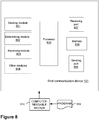
- Figure 7 shows a non-limiting example of a message sequence chart according to embodiments herein.
- the first communication device 101 is an eNB and the second communication device is a UE.
- the eNode B configures the UE with the additional TDD configuration for the one carrier 143, and the CSI reporting parameters.
- the CSI parameters have been described earlier.
- the UE receives the configuration message at 702, in accordance with Action 602. From the reference signals, e.g., cell specific and/or UE specific signals transmitted by the eNB at 703, the UE estimates the CSI at 704 according to Action 602.
- the UE conveys this information in the first channel information report using PUCCH of the primary carrier 141 with f1 at T1, which is received by the eNB at 706 in accordance with Action 503.
- the eNB determines the parameters for downlink transmission, such as MCS, power, PRBs, etc... based on the received CSI at 706.
- the eNB transmits the downlink control channels PCFICH and PDCCH, and the data traffic channel PDSCH at 709.
- the UE estimates CSI parameters for the third carrier, referred to herein as the one carrier 143, and conveys this information in the second channel information report using PUCCH of the one or more secondary carriers 142 with f2 at 711, in accordance with Action 605.
- the second channel information report is received by the eNB at 712, according to Action 504.
- the UE may estimate the CSI parameters and conveys a third channel information report using the primary carrier 141 PUCCH, where T p1 is the periodicity of the CSI reporting on the primary carrier 141.
- the parameters T p1 , T p2 and the difference T2-T1 may be configured by the eNB as part of CSI reporting parameters in the configuration message, which may be a higher layer signaling message.
- the first communication device 101 is configured to send the configuration message to the second communication device 102.
- the first communication device 101 may comprise the following arrangement depicted in Figure 8 .
- the first communication device 101 and the second communication device 102 are configured to operate in the communications network 100.
- the one carrier 143 is a downlink, non-standalone carrier.
- the first communication device 101 is further configured to, e.g., by means of a sending module 801 configured to, send the configuration message to the second communication device 102.
- the configuration message is configured to configure the second communication device 102 to report channel information about the one carrier 143 to the first communication device 101.
- the configuration message is also configured to configure the second communication device 102 to report the channel information on the primary carrier 141 and on the one or more secondary carriers 142.
- the sending module 801 may be a processor 805 of the first communication device 101, or an application running on such processor.
- the first communication device 101 may be further configured to, e.g., by means of a determining module 802 configured to, determine the information related to the configuration message, the information comprising one or more of: a) the information relating to the one carrier 143, b) the information relating to the primary carrier 141 and the one or more secondary carriers 142, c) the information relating to the reporting time for each of the primary carrier 141 and the one or more secondary carriers 142, the reporting time being for the second communication device 102 to report the channel information.
- the determining module 802 may be the processor 805 of the first communication device 101, or an application running on such processor.
- the configuration message may comprise one or more of: a) the determined information relating to the one carrier 143, b) the determined information relating to the primary carrier 141 and the one or more secondary carriers 142, and c) the determined information relating to the reporting time for each of the primary carrier 141 and the one or more secondary carriers 142.
- the determined information relating to the reporting time for each of the primary carrier 141 and the one or more secondary carriers 142 may comprise one or more of: a) the initial reporting time for the primary carrier 141 (T1) and the one or more secondary carriers 142 (T2), b) the periodicity (T p1 , T p2 ) of reporting for each one of the primary carrier 141 and the one or more secondary carriers 142, c) the time difference of reporting between the reporting time for the one or more pairs of the primary carrier 141 and the one or more secondary carriers 142 (T2-T1), and d) the periodicity (T P ) of reporting for all of the primary carrier 141 and the one or more secondary carriers 142.
- the configuration message may be configured to further configure the second communication device 102 to report the channel information on the primary carrier 141 in a first time period (T p1 ) and on the one or more secondary carriers 142 in a second time period (T p2 ).
- the configuration message may be configured to further configure the second communication device 102 to report the channel information alternatively on the primary carrier 141 and on the one or more secondary carriers 142.
- the first communication device 101 may be further configured to, e.g., by means of a receiving module 803 configured to, receive the first channel information report from the second communication device 102 about the one carrier 143 in the primary carrier 141, according to the sent configuration message.
- the receiving module 803 may be the processor 805 of the first communication device 101, or an application running on such processor.
- the first communication device 101 may be further configured to, e.g., by means of the receiving module 803 configured to, receive the second channel information report from the second communication device 102 for the one carrier 143 in the first secondary carrier of the one or more secondary carriers 142, according to the sent configuration message.
- the first communication device101 may be configured to perform other actions with other modules 804 configured to perform these actions within the first communication device101.
- Each of the other modules 804 may be the processor 805 of the first communication device101, or an application running on such processor.
- the embodiments herein may be implemented through one or more processors, such as the processor 805 in the first communication device 101 depicted in Figure 8 , together with computer program code for performing the functions and actions of the embodiments herein.
- the program code mentioned above may also be provided as a computer program product, for instance in the form of a data carrier carrying computer program code for performing the embodiments herein when being loaded into the in the first communication device 101.
- a data carrier carrying computer program code for performing the embodiments herein when being loaded into the in the first communication device 101.
- One such carrier may be in the form of a CD ROM disc. It is however feasible with other data carriers such as a memory stick.
- the computer program code may furthermore be provided as pure program code on a server and downloaded to the first communication device 101.
- the first communication device 101 may further comprise a memory 806 comprising one or more memory units.
- the memory 806 is arranged to be used to store obtained information, store data, configurations, schedulings, and applications etc. to perform the methods herein when being executed in the first communication device 101.
- the first communication device 101 may receive information, e.g., from the second communication device 102, through a receiving port 807.
- the receiving port 807 may be, for example, connected to the two or more antennas in first communication device 101.
- the first communication device 101 may receive information from another structure in the communications network 100 through the receiving port 807. Since the receiving port 807 may be in communication with the processor 805, the receiving port 807, may then send the received information to the processor 805.
- the receiving port 807 may also be configured to receive other information.
- the processor 805 in the first communication device 101 may be further configured to transmit or send information to e.g., to the second communication device 102, through a sending port 808, which may be in communication with the processor 805 and the memory 806.
- the first communication device101 may comprise an interface unit to facilitate communications between the first communication device101 and other nodes or devices, e.g., the second communication device 102.
- the interface may, for example, include a transceiver configured to transmit and receive radio signals over an air interface in accordance with a suitable standard.
- the sending module 801, the determining module 802, the receiving module 803, and the other modules 804 described above may refer to a combination of analog and digital modules, and/or one or more processors configured with software and/or firmware, e.g., stored in memory, that, when executed by the one or more processors such as the processor 805 perform as described above.
- processors as well as the other digital hardware, may be included in a single Application-Specific Integrated Circuit (ASIC), or several processors and various digital hardware may be distributed among several separate components, whether individually packaged or assembled into a System-on-a-Chip (SoC).
- ASIC Application-Specific Integrated Circuit
- SoC System-on-a-Chip
- the different modules 801-804 described above may be implemented as one or more applications running on one or more processors such as the processor 805.
- the methods according to the embodiments described herein for the first communication device 101 may be implemented by means of a computer program 809 product, comprising instructions, i.e., software code portions, which, when executed on at least one processor 805, cause the at least one processor 805 to carry out the actions described herein, as performed by the first communication device 101.
- the computer program 809 product may be stored on a computer-readable storage medium 810.
- the computer-readable storage medium 810, having stored thereon the computer program 809 may comprise instructions which, when executed on at least one processor 805, cause the at least one processor 805 to carry out the actions described herein, as performed by the first communication device 101.
- the computer-readable storage medium 810 may be a non-transitory computer-readable storage medium, such as a CD ROM disc, or a memory stick.
- the computer program 809 product may be stored on a carrier containing the computer program 809 just described, wherein the carrier is one of an electronic signal, optical signal, radio signal, or the computer-readable storage medium, as described above.
- the second communication device 102 is configured to report channel information to the first communication device 101.
- the second communication device 102 may comprise the following arrangement depicted in Figure 9 .
- the first communication device 101 and the second communication device 102 are configured to operate in the communications network 100.
- the one carrier 143 is a downlink, non-standalone carrier.
- the second communication device 102 is further configured to, e.g., by means of a receiving module 901 configured to, receive the configuration message from the first communication device 101.
- the configuration message is configured to configure the second communication device 102 to report the channel information about the one carrier 143 to the first communication device 101.
- the configuration message is also configured to further configure the second communication device 102 to report the channel information on the primary carrier 141 and on the one or more secondary carriers 142.
- the receiving module 901 may be a processor 905 of the second communication device 102, or an application running on such processor.
- the first communication device 101 is further configured to, e.g., by means of a sending module 902 configured to, send the first channel information report to the first communication device 101 for the one carrier 143 on the primary carrier 141, according to the received configuration message.
- the sending module 902 may be the processor 905 of the second communication device 102, or an application running on such processor.
- the first communication device 101 may be further configured to, e.g., by means of the sending module 902 configured to, send the second channel information report to the first communication device 101 for the one carrier 143 on the first secondary carrier of the one or more secondary carriers 142, according to the received configuration message.
- to send the first channel information report according to the received configuration message may be configured to be in the first time period (T p1 ), and to send the second channel information report according to the received configuration message may be configured to be in the second time period (T p2 ).
- the configuration message may be for further configuring the second communication device 102 to report the channel information alternatively on the primary carrier 141 and on the one or more secondary carriers 142.
- the received configuration message may comprise one or more of: a) the information relating to the one carrier 143, b) the information relating to the primary carrier 141 and the one or more secondary carriers 142 which the second communication device 102 is to use to report the channel information, and c) the information relating to the reporting time for each of the primary carrier 141 and the one or more secondary carriers 142.
- the information relating to the reporting time for each of the primary carrier 141 and the one or more secondary carriers 142 may comprise one or more of: a) the initial reporting time for the primary carrier 141 (T1) and the one or more secondary carriers 142 (T2), b) the periodicity (T p1 , T p2 ) of reporting for each one of the primary carrier 141 and the one or more secondary carriers 142, c) the time difference of reporting between the reporting time for the one or more pairs of the primary carrier 141 and the one or more secondary carriers 142 (T2-T1), and d) the periodicity (T P ) of reporting for all of the primary carrier 141 and the one or more secondary carriers 142.
- the second communication device 102 may be further configured to, e.g., by means of a determining module 903 configured to, determine the first channel information to be comprised in the first channel information report, according to the received configuration message.
- the determining module 903 may be the processor 905 of the second communication device 102, or an application running on such processor.
- the first communication device 101 may be further configured to, e.g., by means of the determining module 903 configured to, determine the second channel information to be comprised in the second channel information report, according to the received configuration message.
- the second communication device 102 may be configured to perform other actions with other modules 904 configured to perform these actions within the second communication device 102.
- Each of the other modules 904 may be the processor 905 of the second communication device 102, or an application running on such processor.
- the embodiments herein may be implemented through one or more processors, such as the processor 905 in second communication device 102 depicted in Figure 9 , together with computer program code for performing the functions and actions of the embodiments herein.
- the program code mentioned above may also be provided as a computer program product, for instance in the form of a data carrier carrying computer program code for performing the embodiments herein when being loaded into the in the second communication device 102.
- a data carrier carrying computer program code for performing the embodiments herein when being loaded into the in the second communication device 102.
- One such carrier may be in the form of a CD ROM disc. It is however feasible with other data carriers such as a memory stick.
- the computer program code may furthermore be provided as pure program code on a server and downloaded to the second communication device 102.
- the second communication device 102 may further comprise a memory 906, comprising one or more memory units.
- the memory 906 is arranged to be used to store obtained information, store data, configurations, schedulings, and applications etc. to perform the methods herein when being executed in the second communication device 102.
- the second communication device 102 may receive information, e.g., from the first communication device 101, through a receiving port 907.
- the receiving port 907 may be, for example, connected to the two or more antennas in the second communication device 102.
- the second communication device 102 may receive information from another structure in the communications network 100 through the receiving port 907. Since the receiving port 907 may be in communication with the processor 905, the receiving port 907, may then send the received information to the processor 905.
- the receiving port 907 may also be configured to receive other information.
- the processor 905 in the second communication device 102 may be further configured to transmit or send information to e.g., to the first communication device 101, through a sending port 908, which may be in communication with the processor 905 and the memory 906.
- the second communication device 102 may comprise an interface unit to facilitate communications between the second communication device 102 and other nodes or devices, e.g., the first communication device101.
- the interface may, for example, include a transceiver configured to transmit and receive radio signals over an air interface in accordance with a suitable standard.
- the receiving module 901, the sending module 902, the determining module 903, and the other modules 904, described above may refer to a combination of analog and digital modules, and/or one or more processors configured with software and/or firmware, e.g., stored in memory, that, when executed by the one or more processors such as the processor 905 perform as described above.
- processors as well as the other digital hardware, may be included in a single Application-Specific Integrated Circuit (ASIC), or several processors and various digital hardware may be distributed among several separate components, whether individually packaged or assembled into a System-on-a-Chip (SoC).
- ASIC Application-Specific Integrated Circuit
- SoC System-on-a-Chip
- the different modules 901-904 described above may be implemented as one or more applications running on one or more processors such as the processor 905.
- the methods according to the embodiments described herein for the second communication device 102 may be implemented by means of a computer program 909 product, comprising instructions, i.e., software code portions, which, when executed on at least one processor 905, cause the at least one processor 905 to carry out the actions described herein, as performed by the second communication device 102.
- the computer program 909 product may be stored on a computer-readable storage medium 910.
- the computer-readable storage medium 910, having stored thereon the computer program 909 may comprise instructions which, when executed on at least one processor 905, cause the at least one processor 905 to carry out the actions described herein, as performed by the second communication device 102.
- the computer-readable storage medium 910 may be a non-transitory computer-readable storage medium, such as a CD ROM disc, or a memory stick.
- the computer program 909 product may be stored on a carrier containing the computer program 909 just described, wherein the carrier is one of an electronic signal, optical signal, radio signal, or the computer-readable storage medium, as described above.
- the eNode B may need to send the scheduling information whenever it schedules the UE with downlink data.
- the first 3 OFDM symbols in the subframe may be used for transmit the PDCCH.
- the exact number of OFDM symbols may be indicated by the contents of the PCFICH.
- Figure 10a shows the link throughput performance of an LTE system with control channel overhead of 1-3 OFDM symbols. For reference purposes, the link performance without any overhead of control channel is also plotted. It may be seen that the link throughput, represented in Megabytes per second (Mbps) is reduced when the overhead increases.
- Figure 10b shows that the percentage of degradation at a Signal to Noise Ratio (SNR) of 30 deciBels (dB) is around 10-27 %, where the 10 % corresponds to the overhead of 1 OFDM symbol and 27 % of loss corresponds to the 3 OFDM symbols of overhead.
- SNR Signal to Noise Ratio
- dB deciBels
- Further disclosure herein may be related to wireless communication systems and in particular a method related to transmitting downlink control channel in time division duplex systems, that is, to a method to transmit downlink control channel in a TDD wireless communication system. Further disclosure herein may be related to Downlink control channel, TDD, FDD, carrier aggregation, downlink only, LTE, LTE-A, PDCCH, ePDCCH.
- the eNode B may indicate to the UE about the scheduling parameters, in a similar way to the conventional procedure. In addition, it may indicate for how many subframes the scheduling information may be valid, and the partial scheduling that may be valid for the remaining subframes. In the subsequent, subframes, it may not transmit any control information to the UE. Hence, the eNode B may use the first 3 OFDM symbols of these subframes for data transmission, thereby improving the link and system throughput.
- first communication device e.g., a transmitting device
- second communication device e.g., a receiving device related examples.
- FIG 11 depicts an example of a communications network 1100 in which examples herein may be implemented.
- the wireless communications network 1100 has a similar description as the communications network 100, and will therefore not be repeated here, unless otherwise noted.
- the communications network 1100 comprises a first communication device 1101 and a second communication device 1102.
- the first communication device 1101 has a similar description as the first communication device 101 described earlier, and will therefore not be repeated here.
- the second communication device 1102 has a similar description as the second communication device 102 described earlier, and will therefore not be repeated here.
- the communications network 1100 comprises a plurality of network nodes whereof the network node 1110 is depicted in Figure 11 .
- the network node 1110 has a similar description as the network node 110 described earlier, and will therefore not be repeated here.
- the network node 110 serves a cell 1130.
- the communications network 1100 may comprise more cells similar to cell 1130, served by their respective network nodes. This is not depicted in Figure 11 for the sake of simplicity.
- wireless device 1120 A number of wireless devices are located in the communications network 1100. In the example scenario of Figure 11 , only one wireless device is shown, wireless device 1120. Any reference to a "user node”, “UE”, “mobile station” or “MS” herein is meant to comprise a reference to the wireless device 1120, indistinctively, unless noted otherwise.
- the wireless device 1120 has a similar description as the wireless device 120 described earlier, and will therefore not be repeated here.
- the wireless device 1120 is a wireless communication device such as a mobile station which is also known as e.g. mobile terminal, wireless terminal and/or UE.
- the device is wireless, i.e., it is enabled to communicate wirelessly in the wireless communication network 1100, sometimes also referred to as a cellular radio system or cellular network.
- the communication may be performed e.g., between two devices, between a device and a regular telephone and/or between a device and a server.
- the communication may be performed e.g., via a RAN and possibly one or more core networks, comprised within the communications network 1100.
- the wireless device 1120 may further be referred to as a mobile telephone, cellular telephone, or laptop with wireless capability, just to mention some further examples.
- the wireless device 1120 in the present context may be, for example, portable, pocket-storable, hand-held, computer-comprised, or vehicle-mounted mobile devices, enabled to communicate voice and/or data, via the RAN, with another entity, such as a server, a laptop, a Personal Digital Assistant (PDA), or a tablet computer, sometimes referred to as a surf plate with wireless capability, Machine-to-Machine (M2M) devices, devices equipped with a wireless interface, such as a printer or a file storage device or any other radio network unit capable of communicating over a radio link in a cellular communications system.
- M2M Machine-to-Machine
- the wireless device 1120 may communicate with the network node 1110 over a radio link 1160, e.g., via a primary carrier, such as the primary carrier 141 and a secondary carrier, such as any one of the one or more secondary carriers 142.
- a primary carrier such as the primary carrier 141
- a secondary carrier such as any one of the one or more secondary carriers 142.
- the first communication device further disclosure relates to Figure 12 and 13 .
- Figure 12 is a flowchart illustrating an example of a method performed by a first communication device such as the first communication device 1101, e.g., the network node 1110.
- Figure 13 is a block diagram of a first communication device that is configured according to further disclosure.
- the method performed by the first communication device is for sending a downlink control channel to a second communication device, such as the second communication device 1102, e.g., the wireless device 1120.
- the first communication device 1101 and the second communication device 1102 operate in the communications network 1100, e.g. a wireless communications network.
- the method may comprise one or more of the following actions:
- the determining 1201 the number of subsets of time-frequency resources in the set of time-frequency resources may further comprise:
- the determining 1202 of the information is based on the determined buffer size and on a channel state information reported by the second communication device 1102.
- the communications network 1100 may be a TDD communications network, also referred to herein as a TDD wireless communications system.
- ⁇ Encoding 1203 the determined first information and the determined second information into the first part and the second part, respectively of the downlink control channel using identifier information for the second communication device 1102, and performing rate matching prior to sending 1204 the downlink control channel to the second communication device 1102.
- the first communication device 1101 may be configured to perform this action 1203, e.g. by means of an encoding module 1303 configured to perform this action, within the first communication device 1101.
- the encoding module 1303 may be the processor 1304 of the first communication device 1101, or an application running on such processor.
- the first communication device 1101 may not send downlink control channel information in the remaining number of subsets of time-frequency resources in the set of time-frequency resources.
- the first communication device 1101 may be configured to perform other actions with other modules 1308 configured to perform these actions within the first communication device 1101.
- Each of the other modules 1308 may be the processor 1304 of the first communication device 1101, or an application running on such processor.
- the first communication device 1101 may comprise the arrangement depicted in Figure 13 .
- the detailed description of the arrangement of Figure 13 corresponds to that provided above in relation to Figure 8 , unless noted above in relation to the determining module 1301, the sending module 1302 and the encoding module 1303, and will thus not be repeated here.
- determining module 1301, the sending module 1302, the encoding module 1303 and the other modules 1308, described above may refer to a combination of analog and digital modules, as described earlier regarding the modules of Figure 8 .
- Figure 12 is a flowchart illustrating an example of a method performed by a second communication device such as the second communication device 1102, e.g., the wireless device 1120.
- Figure 15 is a block diagram of a second communication device that is configured according to the further disclosure.
- the method performed by the second communication device is for receiving the downlink control channel from the first communication device 1101.
- the first communication device 1101 and the second communication device 1102 operate in the communications network 1100.
- the method may comprise one or more of the following actions:
- the second communication device 1102 may be configured to perform other actions with other modules 1503 configured to perform these actions within the second communication device 1102.
- Each of the other modules 1503 may be the processor 1504 of the second communication device 1102, or an application running on such processor.
- the second communication device 1102 may comprise the arrangement depicted in Figure 15 .
- the detailed description of the arrangement of Figure 15 corresponds to that provided above in relation to Figure 9 , unless noted above in relation to the receiving module 1501, the detecting and decoding module 1502 and the other module 1503, and will thus not be repeated here.
- the receiving module 1501, the detecting and decoding module 1502 and the other module 1503, described above may refer to a combination of analog and digital modules, as described earlier regarding the modules of Figure 9 .
- an eNB may be used as an illustrative example of the first communication device 1101, and a UE may be used as an illustrative example of the second communication device 1102.
- TDD configuration 10:0:0 or 9:1:0 may be configured on a secondary carrier, and the number of UEs which may be capable of receiving these configurations may be very low.
- these configurations may be invoked when there may be a heavy downlink data available at the transmitter.
- the probability of scheduling the same UE on successive subframes on these carriers may be very high.
- the eNode B instead of sending downlink control information on every TTI, the eNode B may send the control information only once in a frame and indicate to the UE how long the downlink control information is valid for.
- the control channel may consist of two parts, where the first part may be the conventional control channel which is applicable for the current TTI.
- the information in the part 2 may be used for indicating the remaining TTIs in that frame where the scheduling information indicated in the part 2 may be valid.
- part 2 may need to have new fields such as modulation, transport block size, number of transmission layers, precoding information valid for the remaining TTIs in the frame. It may need to indicate the number of TTIs in which the downlink scheduling parameters as indicated in the part 2, such as modulation, transport block size, are valid.
- it may need to send the HARQ/Redundancy Version (RV) information about the successive transmissions in the frame.
- RV HARQ/Redundancy Version
- precoding information as indicated in the part 1 may be valid for all the remaining TTIs. Hence, there may be no need to indicate them in the part 2.
- the top part of Figure 17 shows the frame structure using a conventional method of transmitting data in a frame. It may be observed that in every TTI, first 1 (minimum)-3 (maximum) symbols are used for transmitting control information indicating to the UE that data is transmitted to the specific UE in that TTI.
- Figure 17 also shows the proposed method of transmitting control and data in the lower part, wherein in the first TTI, the control information may be sent, which indicates for how many subframes the scheduling parameters may be valid, and the relevant information for the TTIs in which it may be scheduled.
- control channel which may be sent in the first TTI may need to be bigger in size, as it may need new fields, such as the number of TTIs the downlink scheduling parameters is valid, in addition to the modulation, transport block size, number of transmission layers, precoding information, HARQ/RV information about the successive transmissions in the frame for part 2, etc.
- Figure 18 shows the link throughput performance of an LTE system with the proposed method for control channel transmission, according to a simulation of the further disclosure.
- the control channel 3-OFDM symbols
- the control channel symbols 1-3 OFDM symbols
- the control channel symbols may be used for PDSCH. That is, all the 14 OFDM symbols are used for PDSCH. It may be observed that the significant performance improvement over the conventional method of using 3 OFDM symbols.
- control channel may be transmitted in the first TTI with the proposed method.
- the method may be equally applicable in any one of the TTIs in the frame.
- the proposed control channel may be transmitted in the 5th TTI of the frame, where the bits in the part 2 may indicate how many TTIs the part 2 scheduling information may be valid.
- control information may be sent on the last TTI of the frame, and the bits in the part 2 may indicate how many TTIs the part 2 scheduling information may be valid in the next frame.
- Method at the network node 1110 for transmitting downlink control information on the component carrier as an example of the method performed by the first communication device 1101.
- the network node may need to identify how many TTIs it may schedule the UE consecutively. For this, the network node may determine which UE may need downlink data transmission, and what may be the buffer size available for downlink data transmission for the specific UE. Note that, from the UE feedback, it may get the channel state information as explained in section "Frequency Division Duplex". Based on the CSI and the available buffer, it may estimate the TTIs. As explained in section "General Description of the further disclosure", some of the parameters such as precoding weights, number of transmission layers may be same for the current TTI and the remaining TTIs.
- the network node may encode them in the binary format, channel coded with rate matching and transmitted in the first 1-3 OFDM symbols of the current TTI on the component carrier, i.e. the carrier where the downlink data is transmitted.
- the steps for implementing the proposed method by the first communication device 1101 are shown in a non-limiting example in the flowchart of Figure 19 .
- the first communication device 1101 may be the network node 1110, with component carrier scheduling.
- the receiving node may check the downlink control channel, PCFICH then PDCCH, do a cyclic redundancy check (CRC), and identify that the network schedules the intended UE. Once it decodes the part 1 and part 2 information, it may use the parameters in the part 1 to detect and decode the POSCH of the current TTI using part 1 information, and detect and decode the POSCH of the remaining TTIs using part 2 information.
- PCFICH downlink control channel
- PDCCH do a cyclic redundancy check
- An advantage of the further disclosure herein is a significant improvement in the link throughput due to low overhead of the control channel.
Landscapes
- Engineering & Computer Science (AREA)
- Signal Processing (AREA)
- Computer Networks & Wireless Communication (AREA)
- Quality & Reliability (AREA)
- Mobile Radio Communication Systems (AREA)
Claims (14)
- Procédé réalisé par un nœud de réseau (101) pour l'envoi d'un message de configuration à un équipement utilisateur (102), le nœud de réseau (101) et l'équipement utilisateur (102) fonctionnant dans un réseau de communications (100) d'évolution à long terme, LTE ou 5G, le procédé comprenant :
l'envoi (502) du message de configuration à l'équipement utilisateur (102), le message de configuration étant destiné à configurer l'équipement utilisateur (102) pour signaler des informations de canal concernant une porteuse (143) au nœud de réseau (101), le message de configuration étant destiné à configurer l'équipement utilisateur (102) pour signaler des informations de canal sur une porteuse primaire (141) et sur au moins une porteuse secondaire (142), caractérisé en ce que le message de configuration est destiné à configurer davantage l'équipement utilisateur (102) pour signaler les informations de canal sur la porteuse primaire (141) dans une première période (Tp1) et sur l'au moins une porteuse secondaire (142) dans une deuxième période (Tp2), dans lequel la porteuse (143) est une porteuse non autonome à liaison descendante uniquement. - Procédé selon la revendication 1, comprenant en outre :la détermination (501) d'informations liées au message de configuration, les informations comprenant au moins les unes parmi : a) des informations de canal relatives à une porteuse (143) dans lequel les informations relatives à la porteuse sont des paramètres pour une configuration TDD additionnelle, b) des informations relatives à une porteuse primaire (141) et au moins une porteuse secondaire (142), la porteuse primaire (141) et l'au moins une porteuse secondaire (142) dont l'équipement utilisateur (102) doit signaler les informations de canal, dans lequel les informations relatives à la porteuse primaire et l'au moins une porteuse secondaire sont le nombre de porteuses et/ou leurs fréquences respectives, c) des informations relatives à un moment de signalement pour chacune de la porteuse primaire (141) et de l'au moins une porteuse secondaire (142), le moment de signalement étant destiné au signalement par l'équipement utilisateur (102) des informations de canal, etdans lequel le message de configuration comprend au moins les unes parmi : a) les informations déterminées relatives à la porteuse (143), b) les informations déterminées relatives à la porteuse primaire (141) et l'au moins une porteuse secondaire (142), et c) les informations déterminées relatives au moment de signalement pour chacune de la porteuse primaire (141) et de l'au moins une porteuse secondaire (142), dans lequel les informations déterminées relatives au moment de signalement pour chacune de la porteuse primaire (141) et de l'au moins une poreuse secondaire (142) comprennent au moins l'un parmi : a) un moment de signalement initial pour la porteuse primaire (141) et l'au moins une porteuse secondaire (142) (T1, T2), b) une périodicité (Tpl, Tp2) de signalement pour chacune de la porteuse primaire (141) et de l'au moins une porteuse secondaire (142), c) une différence de moment de signalement entre un moment de signalement pour au moins une paire de la porteuse primaire (141) et de l'au moins une porteuse secondaire (142) (T2-T1), et d) une périodicité (Tp) de signalement pour l'ensemble de la porteuse primaire (141) et de l'au moins une porteuse secondaire (142).
- Procédé selon l'une quelconque des revendications 1 et 2, dans lequel le procédé comprend en outre :la réception (503) d'un premier signalement d'informations de canal depuis l'équipement utilisateur (102) concernant la porteuse (143) dans la porteuse primaire (141), selon le message de configuration envoyé, etla réception (504) d'un deuxième signalement d'informations de canal depuis l'équipement utilisateur (102) pour la porteuse (143) dans une première porteuse secondaire de l'au moins une porteuse secondaire (142), selon le message de configuration envoyé.
- Programme informatique (809), comprenant des instructions qui, lorsqu'elles sont exécutées sur au moins un processeur (805) d'un nœud de réseau (101), amènent l'au moins un processeur (805) à réaliser le procédé selon l'une quelconque des revendications 1 à 3.
- Support de stockage lisible par ordinateur (810), sur lequel est stocké un programme informatique (809), comprenant des instructions qui, lorsqu'elles sont exécutées sur au moins un processeur (805) d'un nœud de réseau (101), amènent l'au moins un processeur (805) à réaliser le procédé selon l'une quelconque des revendications 1 à 3.
- Procédé réalisé par un équipement utilisateur (102) pour signaler des informations de canal à un nœud de réseau (101), le nœud de réseau (101) et l'équipement utilisateur (102) fonctionnant dans un réseau de communications (100) d'évolution à long terme, LTE ou 5G, le procédé comprenant :la réception (601) d'un message de configuration depuis le nœud de réseau (101), le message de configuration étant destiné à configurer l'équipement utilisateur (102) pour signaler des informations de canal concernant une porteuse (143) au nœud de réseau (101), le message de configuration étant destiné à configurer davantage l'équipement utilisateur (102) pour signaler des informations de canal sur une porteuse primaire (141) et sur au moins une porteuse secondaire (142), dans lequel la porteuse (143) est une porteuse non autonome à liaison descendante uniquement, etl'envoi (604) d'un premier signalement d'informations de canal au nœud de réseau (101) pour la porteuse (143) sur la porteuse primaire (141), selon le message de configuration reçu, et l'envoi (605) d'un deuxième signalement d'informations de canal au nœud de réseau (101) pour la porteuse (143) sur une première porteuse secondaire de l'au moins une porteuse secondaire (142), selon le message de configuration reçu, caractérisé en ce que l'envoi (604) du premier signalement d'informations de canal selon le message de configuration reçu est dans une première période (Tp1), et dans lequel l'envoi (605) du deuxième signalement d'informations de canal selon le message de configuration reçu est dans une deuxième période (Tp2).
- Procédé selon la revendication 6, dans lequel le message de configuration reçu comprend au moins les unes parmi : a) des informations de canal relatives à une porteuse (143) dans lequel les informations relatives à la porteuse sont des paramètres pour une configuration TDD additionnelle, b) des informations relatives à une porteuse primaire (141) et au moins une porteuse secondaire (142), la porteuse primaire (141) et l'au moins une porteuse secondaire (142) dont l'équipement utilisateur (102) doit signaler les informations de canal, dans lequel les informations relatives à la porteuse primaire et l'au moins une porteuse secondaire sont le nombre de porteuses et/ou leurs fréquences respectives, l'équipement utilisateur et c) des informations relatives à un moment de signalement pour chacune de la porteuse primaire (141) et de l'au moins une porteuse secondaire (142), dans lequel les informations relatives au moment de signalement pour chacune de la porteuse primaire (141) et de l'au moins une porteuse secondaire (142) comprennent au moins l'un parmi :
a) un moment de signalement initial pour la porteuse primaire (141) et l'au moins une porteuse secondaire (142) (T1, T2), b) une périodicité (Tpl, Tp2) de signalement pour chacune de la porteuse primaire (141) et de l'au moins une porteuse secondaire (142), c) une différence de moment de signalement entre un moment de signalement pour au moins une paire de la porteuse primaire (141) et de l'au moins une porteuse secondaire (142) (T2-T1), et d) une périodicité (Tp) de signalement pour l'ensemble de la porteuse primaire (141) et de l'au moins une porteuse secondaire (142). - Programme informatique (909), comprenant des instructions qui, lorsqu'elles sont exécutées sur au moins un processeur (905) d'un dispositif utilisateur (102), amènent l'au moins un processeur (905) à réaliser le procédé selon l'une quelconque des revendications 6 et 7.
- Support de stockage lisible par ordinateur (910), sur lequel est stocké un programme informatique (909), comprenant des instructions qui, lorsqu'elles sont exécutées sur au moins un processeur (805) d'un dispositif utilisateur (102), amènent l'au moins un processeur (905) à réaliser le procédé selon l'une quelconque des revendications 6 et 7.
- Nœud de réseau (101) configuré pour envoyer un message de configuration à un équipement utilisateur (102), le nœud de réseau (101) et l'équipement utilisateur (102) étant configurés pour fonctionner dans un réseau de communications (100) d'évolution à long terme, LTE ou 5G, le nœud de réseau (101) étant en outre configuré pour :envoyer le du message de configuration à l'équipement utilisateur (102),le message de configuration étant configuré pour configurer l'équipement utilisateur (102) pour signaler des informations de canal concernant une porteuse (143) au nœud de réseau (101), et le message de configuration étant configuré pour configurer l'équipement utilisateur (102) pour signaler des informations de canal sur une porteuse primaire (141) et sur au moins une porteuse secondaire (142) caractérisé en ce que le message de configuration est configuré pour configurer davantage l'équipement utilisateur (102) pour signaler les informations de canal sur la porteuse primaire (141) dans une première période (Tp1) et sur l'au moins une porteuse secondaire (142) dans une deuxième période (Tp2), dans lequel la porteuse (143) est une porteuse non autonome à liaison descendante uniquement.
- Nœud de réseau (101) selon la revendication 10, qui est en outre configuré pour :déterminer des informations liées au message de configuration, les informations comprenant au moins les unes parmi : a) des informations de canal relatives à une porteuse (143) dans lequel les informations relatives à la porteuse sont des paramètres pour une configuration TDD additionnelle, b) des informations relatives à une porteuse primaire (141) et au moins une porteuse secondaire (142), la porteuse primaire (141) et l'au moins une porteuse secondaire (142) dont l'équipement utilisateur (102) doit signaler les informations de canal, dans lequel les informations relatives à la porteuse primaire et l'au moins une porteuse secondaire sont le nombre de porteuses et/ou leurs fréquences respectives, c) des informations relatives à un moment de signalement pour chacune de la porteuse primaire (141) et de l'au moins une porteuse secondaire (142), le moment de signalement étant destiné au signalement par l'équipement utilisateur (102) des informations de canal, etdans lequel le message de configuration comprend au moins les unes parmi : a) les informations déterminées relatives à la porteuse (143), b) les informations déterminées relatives à la porteuse primaire (141) et l'au moins une porteuse secondaire (142), et c) les informations déterminées relatives au moment de signalement pour chacune de la porteuse primaire (141) et de l'au moins une porteuse secondaire (142), dans lequel les informations déterminées relatives au moment de signalement pour chacune de la porteuse primaire (141) et de l'au moins une poreuse secondaire (142) comprennent au moins l'un parmi : a) un moment de signalement initial pour la porteuse primaire (141) et l'au moins une porteuse secondaire (142) (T1, T2), b) une périodicité (Tpl, Tp2) de signalement pour chacune de la porteuse primaire (141) et de l'au moins une porteuse secondaire (142), c) une différence de moment de signalement entre un moment de signalement pour au moins une paire de la porteuse primaire (141) et de l'au moins une porteuse secondaire (142) (T2-T1), et d) une périodicité (Tp) de signalement pour l'ensemble de la porteuse primaire (141) et de l'au moins une porteuse secondaire (142).
- Nœud de réseau (101) selon l'une quelconque des revendications 10 et 11, dans lequel le nœud de réseau (101) est en outre configuré pour :
recevoir un premier signalement d'informations de canal depuis l'équipement utilisateur (102) concernant la porteuse (143) dans la porteuse primaire, selon le message de configuration envoyé, et recevoir un deuxième signalement d'informations de canal depuis l'équipement utilisateur (102) pour la porteuse (143) dans une première porteuse secondaire de l'au moins une porteuse secondaire (142), selon le message de configuration envoyé. - Équipement utilisateur (102) configuré pour signaler des informations de canal à un nœud de réseau (101), le nœud de réseau (101) et l'équipement utilisateur (102) étant configurés pour fonctionner dans un réseau de communications (100) d'évolution à long terme, LTE ou 5G, l'équipement utilisateur (102) étant en outre configuré pour :recevoir un message de configuration depuis le nœud de réseau (101), le message de configuration étant configuré pour configurer l'équipement utilisateur (102) pour signaler des informations de canal concernant une porteuse (143) au nœud de réseau (101), le message de configuration étant configuré pour configurer davantage l'équipement utilisateur (102) pour signaler des informations de canal sur une porteuse primaire (141) et sur au moins une porteuse secondaire (142), envoyer un premier signalement d'informations de canal au nœud de réseau (101) pour la porteuse (143) sur la porteuse primaire (141), selon le message de configuration reçu, dans lequel la porteuse (143) est une porteuse non autonome à liaison descendante uniquement, etenvoyer un deuxième signalement d'informations de canal au nœud de réseau (101) pour la porteuse (143) sur une première porteuse secondaire de l'au moins une porteuse secondaire (142), selon le message de configuration reçu, caractérisé en ce que l'envoi du premier signalement d'informations de canal selon le message de configuration reçu est dans une première période (Tp1), et dans lequel l'envoi du deuxième signalement d'informations de canal selon le message de configuration reçu est configuré pour être dans une deuxième période (Tp2).
- Équipement utilisateur (102) selon la revendication 13, dans lequel le message de configuration reçu comprend au moins les unes parmi : a) des informations de canal relatives à une porteuse (143) dans lequel les informations relatives à la porteuse sont des paramètres pour une configuration TDD additionnelle, b) des informations relatives à une porteuse primaire (141) et au moins une porteuse secondaire (142), la porteuse primaire (141) et l'au moins une porteuse secondaire (142) dont l'équipement utilisateur (102) doit signaler les informations de canal, dans lequel les informations relatives à la porteuse primaire et l'au moins une porteuse secondaire sont le nombre de porteuses et/ou leurs fréquences respectives, et c) des informations relatives à un moment de signalement pour chacune de la porteuse primaire (141) et de l'au moins une porteuse secondaire (142),
dans lequel les informations relatives au moment de signalement pour chacune de la porteuse primaire (141) et de l'au moins une porteuse secondaire (142) comprennent au moins l'un parmi : a) un moment de signalement initial pour la porteuse primaire (141) et l'au moins une porteuse secondaire (142) (T1, T2), b) une périodicité (Tpl, Tp2) de signalement pour chacune de la porteuse primaire (141) et de l'au moins une porteuse secondaire (142), c) une différence de moment de signalement entre un moment de signalement pour au moins une paire de la porteuse primaire (141) et de l'au moins une porteuse secondaire (142) (T2-T1), et d) une périodicité (Tp) de signalement pour l'ensemble de la porteuse primaire (141) et de l'au moins une porteuse secondaire (142).
Applications Claiming Priority (3)
| Application Number | Priority Date | Filing Date | Title |
|---|---|---|---|
| US201562171295P | 2015-06-05 | 2015-06-05 | |
| US201562171334P | 2015-06-05 | 2015-06-05 | |
| PCT/SE2016/050529 WO2016195583A1 (fr) | 2015-06-05 | 2016-06-03 | Envoi de message de configuration et signalement d'informations de canal sur un canal pucch dans une cellule primaire et dans une cellule secondaire |
Publications (2)
| Publication Number | Publication Date |
|---|---|
| EP3304994A1 EP3304994A1 (fr) | 2018-04-11 |
| EP3304994B1 true EP3304994B1 (fr) | 2021-03-17 |
Family
ID=57440990
Family Applications (1)
| Application Number | Title | Priority Date | Filing Date |
|---|---|---|---|
| EP16730525.9A Active EP3304994B1 (fr) | 2015-06-05 | 2016-06-03 | Envoi de message de configuration et signalement d'informations de canal sur un canal pucch dans une cellule primaire et dans une cellule secondaire |
Country Status (3)
| Country | Link |
|---|---|
| US (1) | US10594433B2 (fr) |
| EP (1) | EP3304994B1 (fr) |
| WO (1) | WO2016195583A1 (fr) |
Families Citing this family (7)
| Publication number | Priority date | Publication date | Assignee | Title |
|---|---|---|---|---|
| EP3304994B1 (fr) * | 2015-06-05 | 2021-03-17 | Telefonaktiebolaget LM Ericsson (PUBL) | Envoi de message de configuration et signalement d'informations de canal sur un canal pucch dans une cellule primaire et dans une cellule secondaire |
| CN106257856B (zh) * | 2015-06-19 | 2021-02-02 | 北京三星通信技术研究有限公司 | 一种传输上行控制信息的方法 |
| CN112615707B (zh) | 2015-06-19 | 2024-04-23 | 北京三星通信技术研究有限公司 | 一种传输上行控制信息的方法 |
| EP3264850B1 (fr) * | 2016-06-30 | 2021-07-21 | HTC Corporation | Dispositif et procédé de gestion de l'accès aux canaux dans une bande sans licence |
| CN108024347B (zh) * | 2016-11-04 | 2022-02-08 | 华为技术有限公司 | 下行信息传输方法、装置和设备 |
| US10256887B2 (en) * | 2017-03-23 | 2019-04-09 | Qualcomm Incorporated | Differential channel state information (CSI) reporting for higher resolution CSI |
| US20210329598A1 (en) * | 2018-08-24 | 2021-10-21 | Nec Corporation | A method, device and computer readable media for sidelink configuration transmission and reception |
Family Cites Families (15)
| Publication number | Priority date | Publication date | Assignee | Title |
|---|---|---|---|---|
| KR101678582B1 (ko) * | 2010-03-22 | 2016-12-06 | 삼성전자주식회사 | 통신 시스템에서의 적응형 링크 적용 방법 및 장치. |
| WO2012077930A2 (fr) * | 2010-12-06 | 2012-06-14 | 엘지전자 주식회사 | Procédé de signalement d'informations d'état des canaux dans un système de communication sans fil et dispositif associé |
| US9735844B2 (en) * | 2011-05-09 | 2017-08-15 | Texas Instruments Incorporated | Channel feedback for coordinated multi-point transmissions |
| US9326155B2 (en) * | 2011-09-23 | 2016-04-26 | Nokia Solutions And Networks Oy | Spectrum sharing using sharing profiles |
| CN102355733B (zh) * | 2011-09-30 | 2017-09-26 | 中兴通讯股份有限公司 | 一种物理上行控制信道的发送方法和用户设备 |
| CN103368715B (zh) * | 2012-03-28 | 2017-10-20 | 电信科学技术研究院 | 一种应答信息的传输方法、系统以及装置 |
| JP6308995B2 (ja) | 2012-04-05 | 2018-04-11 | エルジー エレクトロニクス インコーポレイティド | 無線通信システムにおける搬送波集成方法及び装置 |
| WO2013162261A1 (fr) | 2012-04-23 | 2013-10-31 | 엘지전자 주식회사 | Procédé et appareil permettant de faire des harq dans des systèmes d'agrégation de porteuses |
| WO2013177780A1 (fr) | 2012-05-31 | 2013-12-05 | Qualcomm Incorporated | Atténuation d'interférences d'ue à ue, lors d'un déploiement lte asymétrique |
| US9608783B2 (en) * | 2012-12-03 | 2017-03-28 | Telefonaktiebolaget Lm Ericsson (Publ) | Methods and devices for enabling high user bitrates in mixed-traffic scenarios |
| US8971437B2 (en) * | 2012-12-20 | 2015-03-03 | Google Technology Holdings LLC | Method and apparatus for antenna array channel feedback |
| US8976884B2 (en) * | 2012-12-20 | 2015-03-10 | Google Technology Holdings LLC | Method and apparatus for antenna array channel feedback |
| KR102023671B1 (ko) * | 2013-11-01 | 2019-09-20 | 이노스카이 주식회사 | 주기적 채널상태정보 보고 방법 및 장치 |
| US20150359000A1 (en) * | 2014-06-09 | 2015-12-10 | Qinghua Li | Multi-user scheduling channel status reporting for wi-fi |
| EP3304994B1 (fr) * | 2015-06-05 | 2021-03-17 | Telefonaktiebolaget LM Ericsson (PUBL) | Envoi de message de configuration et signalement d'informations de canal sur un canal pucch dans une cellule primaire et dans une cellule secondaire |
-
2016
- 2016-06-03 EP EP16730525.9A patent/EP3304994B1/fr active Active
- 2016-06-03 US US15/579,511 patent/US10594433B2/en not_active Expired - Fee Related
- 2016-06-03 WO PCT/SE2016/050529 patent/WO2016195583A1/fr active Application Filing
Non-Patent Citations (1)
| Title |
|---|
| None * |
Also Published As
| Publication number | Publication date |
|---|---|
| US10594433B2 (en) | 2020-03-17 |
| WO2016195583A1 (fr) | 2016-12-08 |
| US20180109352A1 (en) | 2018-04-19 |
| EP3304994A1 (fr) | 2018-04-11 |
Similar Documents
| Publication | Publication Date | Title |
|---|---|---|
| EP3304994B1 (fr) | Envoi de message de configuration et signalement d'informations de canal sur un canal pucch dans une cellule primaire et dans une cellule secondaire | |
| CN106471858B (zh) | 在载波聚合中切换到双连接性的方法和用户设备 | |
| WO2016163502A1 (fr) | Terminal utilisateur, station de base sans fil et procédé de communication sans fil | |
| RU2726641C1 (ru) | Сигнализация о местоположении опорных сигналов в слотах и минислотах | |
| WO2020026305A1 (fr) | Terminal utilisateur | |
| Al-Shibly et al. | Carrier aggregation in long term evolution-advanced | |
| US11044700B2 (en) | Non-anchor carrier configuration for NB-IoT | |
| JP6975839B2 (ja) | 等しいサイズのコードブロックのためのトランスポートブロックサイズの決定 | |
| US11558867B2 (en) | PDCCH monitoring periodicity | |
| CN112166574A (zh) | 用于URLLC可靠性的多PCell设计 | |
| US11012986B2 (en) | First communication device, second communication device and methods therein for sending and decoding, respectively, downlink information | |
| US11963028B2 (en) | Dynamic and compact measurement report resolution in wireless systems | |
| US11516716B2 (en) | Bandwidth part/frequency location restriction for L1/L2-centric inter-cell mobility | |
| US9660789B2 (en) | Central network node, first network node, first wireless device, controller network node, and methods therein, of instructing the first network node to transmit to the first wireless device | |
| KR20230069116A (ko) | Uu 휴면 및 사이드링크 송신 그랜트 | |
| WO2021034255A1 (fr) | Traitement de débit de données pour nr-dc avec un fonctionnement mcg et scg dans la même plage de fréquences | |
| WO2016140603A1 (fr) | Noeud de réseau et procédé de configuration de structures de canal de rétroaction adaptative | |
| US20220007347A1 (en) | Shared common beam update across multiple component carriers | |
| WO2023039695A1 (fr) | Rapports d'informations d'état de canal liés à un domaine temporel pour une communication sans fil | |
| US20240056134A1 (en) | Enhancements for non-collocated intra-band deployments | |
| WO2017058072A1 (fr) | Nœud de réseau, équipement utilisateur et procédés associés destinés à l'attribution de ressources servant au trafic de données |
Legal Events
| Date | Code | Title | Description |
|---|---|---|---|
| STAA | Information on the status of an ep patent application or granted ep patent |
Free format text: STATUS: THE INTERNATIONAL PUBLICATION HAS BEEN MADE |
|
| PUAI | Public reference made under article 153(3) epc to a published international application that has entered the european phase |
Free format text: ORIGINAL CODE: 0009012 |
|
| STAA | Information on the status of an ep patent application or granted ep patent |
Free format text: STATUS: REQUEST FOR EXAMINATION WAS MADE |
|
| 17P | Request for examination filed |
Effective date: 20180102 |
|
| AK | Designated contracting states |
Kind code of ref document: A1 Designated state(s): AL AT BE BG CH CY CZ DE DK EE ES FI FR GB GR HR HU IE IS IT LI LT LU LV MC MK MT NL NO PL PT RO RS SE SI SK SM TR |
|
| AX | Request for extension of the european patent |
Extension state: BA ME |
|
| RIN1 | Information on inventor provided before grant (corrected) |
Inventor name: EVERAERE, DOMINIQUE Inventor name: HOYMANN, CHRISTIAN Inventor name: NAMMI, SAIRAMESH |
|
| DAV | Request for validation of the european patent (deleted) | ||
| DAX | Request for extension of the european patent (deleted) | ||
| STAA | Information on the status of an ep patent application or granted ep patent |
Free format text: STATUS: EXAMINATION IS IN PROGRESS |
|
| 17Q | First examination report despatched |
Effective date: 20200326 |
|
| GRAP | Despatch of communication of intention to grant a patent |
Free format text: ORIGINAL CODE: EPIDOSNIGR1 |
|
| STAA | Information on the status of an ep patent application or granted ep patent |
Free format text: STATUS: GRANT OF PATENT IS INTENDED |
|
| INTG | Intention to grant announced |
Effective date: 20210114 |
|
| RIN1 | Information on inventor provided before grant (corrected) |
Inventor name: EVERAERE, DOMINIQUE Inventor name: HOYMANN, CHRISTIAN Inventor name: NAMMI, SAIRAMESH |
|
| GRAS | Grant fee paid |
Free format text: ORIGINAL CODE: EPIDOSNIGR3 |
|
| GRAA | (expected) grant |
Free format text: ORIGINAL CODE: 0009210 |
|
| STAA | Information on the status of an ep patent application or granted ep patent |
Free format text: STATUS: THE PATENT HAS BEEN GRANTED |
|
| AK | Designated contracting states |
Kind code of ref document: B1 Designated state(s): AL AT BE BG CH CY CZ DE DK EE ES FI FR GB GR HR HU IE IS IT LI LT LU LV MC MK MT NL NO PL PT RO RS SE SI SK SM TR |
|
| REG | Reference to a national code |
Ref country code: GB Ref legal event code: FG4D |
|
| REG | Reference to a national code |
Ref country code: CH Ref legal event code: EP |
|
| REG | Reference to a national code |
Ref country code: DE Ref legal event code: R096 Ref document number: 602016054404 Country of ref document: DE |
|
| REG | Reference to a national code |
Ref country code: IE Ref legal event code: FG4D |
|
| REG | Reference to a national code |
Ref country code: AT Ref legal event code: REF Ref document number: 1373463 Country of ref document: AT Kind code of ref document: T Effective date: 20210415 |
|
| REG | Reference to a national code |
Ref country code: NL Ref legal event code: FP |
|
| REG | Reference to a national code |
Ref country code: LT Ref legal event code: MG9D |
|
| PG25 | Lapsed in a contracting state [announced via postgrant information from national office to epo] |
Ref country code: NO Free format text: LAPSE BECAUSE OF FAILURE TO SUBMIT A TRANSLATION OF THE DESCRIPTION OR TO PAY THE FEE WITHIN THE PRESCRIBED TIME-LIMIT Effective date: 20210617 Ref country code: HR Free format text: LAPSE BECAUSE OF FAILURE TO SUBMIT A TRANSLATION OF THE DESCRIPTION OR TO PAY THE FEE WITHIN THE PRESCRIBED TIME-LIMIT Effective date: 20210317 Ref country code: GR Free format text: LAPSE BECAUSE OF FAILURE TO SUBMIT A TRANSLATION OF THE DESCRIPTION OR TO PAY THE FEE WITHIN THE PRESCRIBED TIME-LIMIT Effective date: 20210618 Ref country code: FI Free format text: LAPSE BECAUSE OF FAILURE TO SUBMIT A TRANSLATION OF THE DESCRIPTION OR TO PAY THE FEE WITHIN THE PRESCRIBED TIME-LIMIT Effective date: 20210317 Ref country code: BG Free format text: LAPSE BECAUSE OF FAILURE TO SUBMIT A TRANSLATION OF THE DESCRIPTION OR TO PAY THE FEE WITHIN THE PRESCRIBED TIME-LIMIT Effective date: 20210617 |
|
| REG | Reference to a national code |
Ref country code: AT Ref legal event code: MK05 Ref document number: 1373463 Country of ref document: AT Kind code of ref document: T Effective date: 20210317 |
|
| PG25 | Lapsed in a contracting state [announced via postgrant information from national office to epo] |
Ref country code: SE Free format text: LAPSE BECAUSE OF FAILURE TO SUBMIT A TRANSLATION OF THE DESCRIPTION OR TO PAY THE FEE WITHIN THE PRESCRIBED TIME-LIMIT Effective date: 20210317 Ref country code: RS Free format text: LAPSE BECAUSE OF FAILURE TO SUBMIT A TRANSLATION OF THE DESCRIPTION OR TO PAY THE FEE WITHIN THE PRESCRIBED TIME-LIMIT Effective date: 20210317 Ref country code: LV Free format text: LAPSE BECAUSE OF FAILURE TO SUBMIT A TRANSLATION OF THE DESCRIPTION OR TO PAY THE FEE WITHIN THE PRESCRIBED TIME-LIMIT Effective date: 20210317 |
|
| PG25 | Lapsed in a contracting state [announced via postgrant information from national office to epo] |
Ref country code: SM Free format text: LAPSE BECAUSE OF FAILURE TO SUBMIT A TRANSLATION OF THE DESCRIPTION OR TO PAY THE FEE WITHIN THE PRESCRIBED TIME-LIMIT Effective date: 20210317 Ref country code: AT Free format text: LAPSE BECAUSE OF FAILURE TO SUBMIT A TRANSLATION OF THE DESCRIPTION OR TO PAY THE FEE WITHIN THE PRESCRIBED TIME-LIMIT Effective date: 20210317 Ref country code: EE Free format text: LAPSE BECAUSE OF FAILURE TO SUBMIT A TRANSLATION OF THE DESCRIPTION OR TO PAY THE FEE WITHIN THE PRESCRIBED TIME-LIMIT Effective date: 20210317 Ref country code: CZ Free format text: LAPSE BECAUSE OF FAILURE TO SUBMIT A TRANSLATION OF THE DESCRIPTION OR TO PAY THE FEE WITHIN THE PRESCRIBED TIME-LIMIT Effective date: 20210317 Ref country code: LT Free format text: LAPSE BECAUSE OF FAILURE TO SUBMIT A TRANSLATION OF THE DESCRIPTION OR TO PAY THE FEE WITHIN THE PRESCRIBED TIME-LIMIT Effective date: 20210317 |
|
| PG25 | Lapsed in a contracting state [announced via postgrant information from national office to epo] |
Ref country code: SK Free format text: LAPSE BECAUSE OF FAILURE TO SUBMIT A TRANSLATION OF THE DESCRIPTION OR TO PAY THE FEE WITHIN THE PRESCRIBED TIME-LIMIT Effective date: 20210317 Ref country code: RO Free format text: LAPSE BECAUSE OF FAILURE TO SUBMIT A TRANSLATION OF THE DESCRIPTION OR TO PAY THE FEE WITHIN THE PRESCRIBED TIME-LIMIT Effective date: 20210317 Ref country code: PL Free format text: LAPSE BECAUSE OF FAILURE TO SUBMIT A TRANSLATION OF THE DESCRIPTION OR TO PAY THE FEE WITHIN THE PRESCRIBED TIME-LIMIT Effective date: 20210317 Ref country code: PT Free format text: LAPSE BECAUSE OF FAILURE TO SUBMIT A TRANSLATION OF THE DESCRIPTION OR TO PAY THE FEE WITHIN THE PRESCRIBED TIME-LIMIT Effective date: 20210719 Ref country code: IS Free format text: LAPSE BECAUSE OF FAILURE TO SUBMIT A TRANSLATION OF THE DESCRIPTION OR TO PAY THE FEE WITHIN THE PRESCRIBED TIME-LIMIT Effective date: 20210717 |
|
| REG | Reference to a national code |
Ref country code: DE Ref legal event code: R097 Ref document number: 602016054404 Country of ref document: DE |
|
| PLBE | No opposition filed within time limit |
Free format text: ORIGINAL CODE: 0009261 |
|
| STAA | Information on the status of an ep patent application or granted ep patent |
Free format text: STATUS: NO OPPOSITION FILED WITHIN TIME LIMIT |
|
| PG25 | Lapsed in a contracting state [announced via postgrant information from national office to epo] |
Ref country code: ES Free format text: LAPSE BECAUSE OF FAILURE TO SUBMIT A TRANSLATION OF THE DESCRIPTION OR TO PAY THE FEE WITHIN THE PRESCRIBED TIME-LIMIT Effective date: 20210317 Ref country code: AL Free format text: LAPSE BECAUSE OF FAILURE TO SUBMIT A TRANSLATION OF THE DESCRIPTION OR TO PAY THE FEE WITHIN THE PRESCRIBED TIME-LIMIT Effective date: 20210317 Ref country code: MC Free format text: LAPSE BECAUSE OF FAILURE TO SUBMIT A TRANSLATION OF THE DESCRIPTION OR TO PAY THE FEE WITHIN THE PRESCRIBED TIME-LIMIT Effective date: 20210317 Ref country code: DK Free format text: LAPSE BECAUSE OF FAILURE TO SUBMIT A TRANSLATION OF THE DESCRIPTION OR TO PAY THE FEE WITHIN THE PRESCRIBED TIME-LIMIT Effective date: 20210317 |
|
| REG | Reference to a national code |
Ref country code: CH Ref legal event code: PL |
|
| 26N | No opposition filed |
Effective date: 20211220 |
|
| PG25 | Lapsed in a contracting state [announced via postgrant information from national office to epo] |
Ref country code: SI Free format text: LAPSE BECAUSE OF FAILURE TO SUBMIT A TRANSLATION OF THE DESCRIPTION OR TO PAY THE FEE WITHIN THE PRESCRIBED TIME-LIMIT Effective date: 20210317 |
|
| REG | Reference to a national code |
Ref country code: BE Ref legal event code: MM Effective date: 20210630 |
|
| PG25 | Lapsed in a contracting state [announced via postgrant information from national office to epo] |
Ref country code: LU Free format text: LAPSE BECAUSE OF NON-PAYMENT OF DUE FEES Effective date: 20210603 |
|
| PG25 | Lapsed in a contracting state [announced via postgrant information from national office to epo] |
Ref country code: LI Free format text: LAPSE BECAUSE OF NON-PAYMENT OF DUE FEES Effective date: 20210630 Ref country code: IT Free format text: LAPSE BECAUSE OF FAILURE TO SUBMIT A TRANSLATION OF THE DESCRIPTION OR TO PAY THE FEE WITHIN THE PRESCRIBED TIME-LIMIT Effective date: 20210317 Ref country code: IE Free format text: LAPSE BECAUSE OF NON-PAYMENT OF DUE FEES Effective date: 20210603 Ref country code: CH Free format text: LAPSE BECAUSE OF NON-PAYMENT OF DUE FEES Effective date: 20210630 |
|
| PG25 | Lapsed in a contracting state [announced via postgrant information from national office to epo] |
Ref country code: IS Free format text: LAPSE BECAUSE OF FAILURE TO SUBMIT A TRANSLATION OF THE DESCRIPTION OR TO PAY THE FEE WITHIN THE PRESCRIBED TIME-LIMIT Effective date: 20210717 Ref country code: FR Free format text: LAPSE BECAUSE OF NON-PAYMENT OF DUE FEES Effective date: 20210630 |
|
| PG25 | Lapsed in a contracting state [announced via postgrant information from national office to epo] |
Ref country code: BE Free format text: LAPSE BECAUSE OF NON-PAYMENT OF DUE FEES Effective date: 20210630 |
|
| PGFP | Annual fee paid to national office [announced via postgrant information from national office to epo] |
Ref country code: NL Payment date: 20220626 Year of fee payment: 7 Ref country code: GB Payment date: 20220628 Year of fee payment: 7 |
|
| PGFP | Annual fee paid to national office [announced via postgrant information from national office to epo] |
Ref country code: DE Payment date: 20220629 Year of fee payment: 7 |
|
| PG25 | Lapsed in a contracting state [announced via postgrant information from national office to epo] |
Ref country code: CY Free format text: LAPSE BECAUSE OF FAILURE TO SUBMIT A TRANSLATION OF THE DESCRIPTION OR TO PAY THE FEE WITHIN THE PRESCRIBED TIME-LIMIT Effective date: 20210317 |
|
| PG25 | Lapsed in a contracting state [announced via postgrant information from national office to epo] |
Ref country code: HU Free format text: LAPSE BECAUSE OF FAILURE TO SUBMIT A TRANSLATION OF THE DESCRIPTION OR TO PAY THE FEE WITHIN THE PRESCRIBED TIME-LIMIT; INVALID AB INITIO Effective date: 20160603 |
|
| REG | Reference to a national code |
Ref country code: DE Ref legal event code: R119 Ref document number: 602016054404 Country of ref document: DE |
|
| REG | Reference to a national code |
Ref country code: NL Ref legal event code: MM Effective date: 20230701 |
|
| GBPC | Gb: european patent ceased through non-payment of renewal fee |
Effective date: 20230603 |
|
| PG25 | Lapsed in a contracting state [announced via postgrant information from national office to epo] |
Ref country code: NL Free format text: LAPSE BECAUSE OF NON-PAYMENT OF DUE FEES Effective date: 20230701 |
|
| PG25 | Lapsed in a contracting state [announced via postgrant information from national office to epo] |
Ref country code: MK Free format text: LAPSE BECAUSE OF FAILURE TO SUBMIT A TRANSLATION OF THE DESCRIPTION OR TO PAY THE FEE WITHIN THE PRESCRIBED TIME-LIMIT Effective date: 20210317 Ref country code: DE Free format text: LAPSE BECAUSE OF NON-PAYMENT OF DUE FEES Effective date: 20240103 Ref country code: GB Free format text: LAPSE BECAUSE OF NON-PAYMENT OF DUE FEES Effective date: 20230603 |