EP3304645B1 - Architecture d'antenne de station de base multifaisceau et multibande simplifiée et sa mise en uvre - Google Patents
Architecture d'antenne de station de base multifaisceau et multibande simplifiée et sa mise en uvre Download PDFInfo
- Publication number
- EP3304645B1 EP3304645B1 EP16798983.9A EP16798983A EP3304645B1 EP 3304645 B1 EP3304645 B1 EP 3304645B1 EP 16798983 A EP16798983 A EP 16798983A EP 3304645 B1 EP3304645 B1 EP 3304645B1
- Authority
- EP
- European Patent Office
- Prior art keywords
- antenna array
- antenna
- array elements
- elements
- band
- Prior art date
- Legal status (The legal status is an assumption and is not a legal conclusion. Google has not performed a legal analysis and makes no representation as to the accuracy of the status listed.)
- Active
Links
- 230000010287 polarization Effects 0.000 claims description 17
- 239000006185 dispersion Substances 0.000 claims description 4
- 238000003491 array Methods 0.000 description 26
- 238000013461 design Methods 0.000 description 19
- 238000010168 coupling process Methods 0.000 description 4
- 238000005859 coupling reaction Methods 0.000 description 4
- 230000009977 dual effect Effects 0.000 description 4
- 230000000694 effects Effects 0.000 description 4
- 230000010363 phase shift Effects 0.000 description 4
- 238000013459 approach Methods 0.000 description 3
- 230000008878 coupling Effects 0.000 description 3
- 238000000034 method Methods 0.000 description 3
- 238000004891 communication Methods 0.000 description 2
- 230000001808 coupling effect Effects 0.000 description 2
- 239000000203 mixture Substances 0.000 description 2
- 230000005855 radiation Effects 0.000 description 2
- 230000003044 adaptive effect Effects 0.000 description 1
- 239000002131 composite material Substances 0.000 description 1
- 238000002474 experimental method Methods 0.000 description 1
- 230000003993 interaction Effects 0.000 description 1
- 238000002955 isolation Methods 0.000 description 1
- 238000004519 manufacturing process Methods 0.000 description 1
- 230000007246 mechanism Effects 0.000 description 1
- NJPPVKZQTLUDBO-UHFFFAOYSA-N novaluron Chemical compound C1=C(Cl)C(OC(F)(F)C(OC(F)(F)F)F)=CC=C1NC(=O)NC(=O)C1=C(F)C=CC=C1F NJPPVKZQTLUDBO-UHFFFAOYSA-N 0.000 description 1
- 230000004044 response Effects 0.000 description 1
- 230000009466 transformation Effects 0.000 description 1
Images


Classifications
-
- H—ELECTRICITY
- H01—ELECTRIC ELEMENTS
- H01Q—ANTENNAS, i.e. RADIO AERIALS
- H01Q1/00—Details of, or arrangements associated with, antennas
- H01Q1/52—Means for reducing coupling between antennas; Means for reducing coupling between an antenna and another structure
- H01Q1/521—Means for reducing coupling between antennas; Means for reducing coupling between an antenna and another structure reducing the coupling between adjacent antennas
- H01Q1/523—Means for reducing coupling between antennas; Means for reducing coupling between an antenna and another structure reducing the coupling between adjacent antennas between antennas of an array
-
- H—ELECTRICITY
- H01—ELECTRIC ELEMENTS
- H01Q—ANTENNAS, i.e. RADIO AERIALS
- H01Q5/00—Arrangements for simultaneous operation of antennas on two or more different wavebands, e.g. dual-band or multi-band arrangements
- H01Q5/40—Imbricated or interleaved structures; Combined or electromagnetically coupled arrangements, e.g. comprising two or more non-connected fed radiating elements
- H01Q5/48—Combinations of two or more dipole type antennas
-
- H—ELECTRICITY
- H01—ELECTRIC ELEMENTS
- H01Q—ANTENNAS, i.e. RADIO AERIALS
- H01Q1/00—Details of, or arrangements associated with, antennas
- H01Q1/12—Supports; Mounting means
- H01Q1/22—Supports; Mounting means by structural association with other equipment or articles
- H01Q1/24—Supports; Mounting means by structural association with other equipment or articles with receiving set
- H01Q1/241—Supports; Mounting means by structural association with other equipment or articles with receiving set used in mobile communications, e.g. GSM
- H01Q1/246—Supports; Mounting means by structural association with other equipment or articles with receiving set used in mobile communications, e.g. GSM specially adapted for base stations
-
- H—ELECTRICITY
- H01—ELECTRIC ELEMENTS
- H01Q—ANTENNAS, i.e. RADIO AERIALS
- H01Q21/00—Antenna arrays or systems
- H01Q21/06—Arrays of individually energised antenna units similarly polarised and spaced apart
- H01Q21/061—Two dimensional planar arrays
- H01Q21/062—Two dimensional planar arrays using dipole aerials
-
- H—ELECTRICITY
- H01—ELECTRIC ELEMENTS
- H01Q—ANTENNAS, i.e. RADIO AERIALS
- H01Q21/00—Antenna arrays or systems
- H01Q21/06—Arrays of individually energised antenna units similarly polarised and spaced apart
- H01Q21/061—Two dimensional planar arrays
- H01Q21/065—Patch antenna array
-
- H—ELECTRICITY
- H01—ELECTRIC ELEMENTS
- H01Q—ANTENNAS, i.e. RADIO AERIALS
- H01Q21/00—Antenna arrays or systems
- H01Q21/24—Combinations of antenna units polarised in different directions for transmitting or receiving circularly and elliptically polarised waves or waves linearly polarised in any direction
-
- H—ELECTRICITY
- H01—ELECTRIC ELEMENTS
- H01Q—ANTENNAS, i.e. RADIO AERIALS
- H01Q21/00—Antenna arrays or systems
- H01Q21/30—Combinations of separate antenna units operating in different wavebands and connected to a common feeder system
-
- H—ELECTRICITY
- H01—ELECTRIC ELEMENTS
- H01Q—ANTENNAS, i.e. RADIO AERIALS
- H01Q3/00—Arrangements for changing or varying the orientation or the shape of the directional pattern of the waves radiated from an antenna or antenna system
- H01Q3/26—Arrangements for changing or varying the orientation or the shape of the directional pattern of the waves radiated from an antenna or antenna system varying the relative phase or relative amplitude of energisation between two or more active radiating elements; varying the distribution of energy across a radiating aperture
- H01Q3/2605—Array of radiating elements provided with a feedback control over the element weights, e.g. adaptive arrays
-
- H—ELECTRICITY
- H01—ELECTRIC ELEMENTS
- H01Q—ANTENNAS, i.e. RADIO AERIALS
- H01Q5/00—Arrangements for simultaneous operation of antennas on two or more different wavebands, e.g. dual-band or multi-band arrangements
- H01Q5/40—Imbricated or interleaved structures; Combined or electromagnetically coupled arrangements, e.g. comprising two or more non-connected fed radiating elements
-
- H—ELECTRICITY
- H01—ELECTRIC ELEMENTS
- H01Q—ANTENNAS, i.e. RADIO AERIALS
- H01Q9/00—Electrically-short antennas having dimensions not more than twice the operating wavelength and consisting of conductive active radiating elements
- H01Q9/04—Resonant antennas
- H01Q9/16—Resonant antennas with feed intermediate between the extremities of the antenna, e.g. centre-fed dipole
- H01Q9/28—Conical, cylindrical, cage, strip, gauze, or like elements having an extended radiating surface; Elements comprising two conical surfaces having collinear axes and adjacent apices and fed by two-conductor transmission lines
- H01Q9/285—Planar dipole
-
- H—ELECTRICITY
- H01—ELECTRIC ELEMENTS
- H01Q—ANTENNAS, i.e. RADIO AERIALS
- H01Q21/00—Antenna arrays or systems
- H01Q21/06—Arrays of individually energised antenna units similarly polarised and spaced apart
- H01Q21/08—Arrays of individually energised antenna units similarly polarised and spaced apart the units being spaced along or adjacent to a rectilinear path
Definitions
- This invention relates to the field of telecommunications. More specifically, this invention relates to multi-band multibeam base-station antenna arrays.
- Multi-band multibeam base station array antennas are able to support multiple radio frequency bands over multiple sectors. These multifunctional antennas can improve the capacity and throughput of the communication system while occupying almost the same physical space on the communication towers.
- multi-band antennas utilize multi-band elements in their architecture.
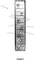
- One example of such a state of the art dual-band antenna is that found in US Patent 7 283 101 (see Figure 1 ). This antenna supports two radio frequency bands with one 65deg beam per polarization for each band. This antenna uses a plurality of both dual-band and single band elements.
- Document CN 103 545 621 A discloses a compact multi-band array antenna.
- Document WO 2012/151210 A1 discloses a tri-pole antenna element and antenna array.
- Document WO 2015/018296 A1 discloses a broadband low-beam-coupling dual-beam phased array.
- Document WO 2014/130877 A1 discloses a multi-array antenna.
- Document US 6, 529, 166 discloses an ultra-wideband multi-beam adaptive antenna.
- Document US 8, 354, 972 discloses a dual-band dual-polarized antenna assembly and dual-polarized antenna array.
- Document US 5, 434, 580 discloses a multifrequency array with composite radiators.
- multi-band elements in multi-band antennas has several shortcomings.
- the non-similarity between multi-band elements and single band elements in a multi-band antenna may cause antenna pattern distortion.
- the different center phases of each multi-band element and single band element may cause dispersion over frequency bands and this thereby weakens the antenna's performance.
- Multi-band elements including dual-band elements, are also complex in both structure and composition/design. This complexity may be problematic for manufacturing, and may also cause Passive Intermodulation, or PIM, issues.
- PIM Passive Intermodulation
- Multiband multibeam planar arrays in particular are more challenging to design especially when it comes to positioning the single band and multiband elements near each other in the limited available space.
- These planar arrays usually are used to provide narrower azimuth beamwidths such as 33 degree beams (or narrower) per polarization for either or both bands (compared to a 65 degree azimuth beamwidth for standard 3 sector implementations).
- the narrower beams can be directed toward boresight or they can be directed in other directions for bisector/multi-sector applications.
- These planar arrays may also include two or more independent antennas in the same reflector for MIMO applications. For these planar arrays, space, both in front of and the back of the reflector, is more limited due to more complex beamforming networks.
- the present invention provides a multibeam multiband architecture that can be implemented in many different applications as shown in different embodiments of this invention.
- the concept is not limited to these embodiments and can be used in a variety of other implementations.
- the present invention provides systems and devices relating to a multi-beam, multi-band antenna system.
- a first antenna array is used for low frequency band beams and this first antenna array uses low band antenna elements.
- At least one second antenna array, for high frequency band beams, is also present with the second antenna array elements being interspersed among the first antenna elements.
- the second antenna elements are spaced within the first antenna array with the second antenna elements being placed in between the first antenna elements.
- Groups of second antenna elements are regularly spaced among the first antenna elements with spacing between groups being larger than element spacing within each group.
- the architecture of the current invention uses two or more types of antenna element.
- antenna elements are used for high frequency band beams while dipole antenna elements are used for low frequency band beams.
- the second antenna elements are deployed in groups of rows with each group of rows being placed between elements or rows of elements of the first antenna array.
- the longitudinal spacing between groups of rows of the second antenna elements are uniform and may be different from the longitudinal spacing between elements within each group of rows. This is done to minimize the coupling effect of antenna elements of the first and second types of antenna elements.
- the antenna elements of different types are selected for minimum coupling between different types.
- patch antenna elements were used for high band frequencies and dipole antenna elements were used for low band frequencies.
- the present invention also includes a new design for an azimuth beamformer and related architectural implementation for improving the crossover point and sidelobe of the beams for high frequency band antenna arrays.
- the present invention provides an antenna system according to claim 1.
- the present invention provides an approach for implementing compact multi-standard multi-beam antennas without the need to use multi-band elements.
- a variety of embodiments are shown as examples and the invention is not limited to these embodiments.
- the present invention utilizes a combination of different element types for low-band and/or high-band applications, without introducing high grating lobes.
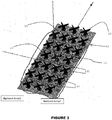
- Embodiment B an antenna array according to Embodiment B detailed above is presented. It should be noted that Embodiment B is presented first as this is the simplest embodiment of the four presented in this document. Figure 2 can therefore serve as a basis for the descriptions and terms which will be used in conjunction with the other embodiments.
- the antenna system 10 has two antenna arrays.
- the first antenna array uses first antenna elements 20 while the second antenna array uses second antenna elements 30.
- the first antenna array uses seven first antenna array elements 20 while the second antenna array uses 48 second antenna array elements 30.
- the second antenna array elements are arranged into groups of eight second antenna array elements 30 per group. For each group, there are two latitudinally arranged rows of four second antenna array elements per row. Within each row, the four second antenna array elements are latitudinally equally spaced apart from adjacent second antenna array elements. It should, however, be noted that the latitudinal spacing between elements within a row may be unequal. The latitudinal spacing may be unequal to shape the azimuth pattern. For this embodiment, the latitudinal spacing between elements was equal. Within each group, a longitudinal spacing d1 separates the two rows.
- the groups of second array elements of the second array are separated by first antenna array elements 20.
- each group of eight second antenna array elements are spaced apart from other groups with a single first antenna array element separating one group from another.
- a longitudinal spacing d2 separates any two adjacent groups of second antenna array elements.
- the longitudinal spacing d2 may be greater than the longitudinal spacing d1 .
- d1 and d2 are not equal to one another. It should, however, be noted that experiments indicate that, for some specific implementations, there might be a preference for the d1 distance being greater than d2 distance. If d1 were equal to d2 , high grating lobes at higher frequencies may be produced.
- the first antenna array elements 20 are dipole antenna elements while the second antenna array elements 30 are patch antenna elements.
- Other antenna elements may, of course, be possible.
- both types of antenna array elements may be dipoles with metallic dipoles being used for high frequency band elements and PCB dipoles being used for low frequency band elements.
- quad dipole antenna elements may be used for the high frequency band elements while cross dipole antenna elements may be used for the low frequency band elements.
- slot antenna elements may be used for high frequency band elements and dipole antenna elements may be used for low frequency band elements.
- each low frequency band element has a small physical footprint so that the high frequency elements can first be located or placed properly.
- the arrangement in Figure 2 allows for minimal coupling effect between the low-band dipole antenna array elements and the high-band antenna element patches when compared to other combinations of element types. Such an arrangement also minimizes the size of the overall antenna system, creating a very compact dual-band antenna.
- the simplified architecture of such an arrangement can be applied to a variety of multi-beam multi-band antenna as shown in different embodiments of the invention.
- the difference in spacing between the values for d1 and d2 as explained above serves multiple purposes.
- dipole elements have very small footprints on or near the reflector surface, they cause much less radiation interference to the radiation mechanism of patch elements when compared to other low band elements such as a patch element.
- the wings of dipoles which are partially extended over the patch elements only produce a small interference effect.
- This architecture therefore creates a smaller overall antenna array size for the same number of antenna elements with minimal coupling between low band and high band elements.
- two rows of patch antenna elements are located between every two dipole antenna array elements.
- the difference between the d1 and d2 spacings also minimizes the dipole effect on the patches and the coupling between the patch antenna elements and the dipole antenna elements, thereby improving antenna performance.
- FIG. 2A azimuth plots for the two arrays illustrated in Figure 2 are presented.
- the top plot is an azimuth plot of the bisector beams for the high band antenna array while the bottom plot is for the low band array.
- a single low band antenna array is used in conjunction with two high band antenna arrays.
- the single low band antenna array consists of multiple dipole antenna elements 20. These dipole antenna elements are positioned in a 3-4-4-3-4-4-3 configuration. This means that, from the top of the figure, the top row of dipole antenna elements (or first array antenna elements) has 3 elements in the row. The next two rows each has 4 first antenna array elements while the following row has only three first antenna array elements. Of the last three rows, the first two each have four dipole antenna elements per row while the last row only has three antenna elements in the row.
- the two high band antenna arrays are circled in Figure 3 and are labeled as "Highband Array1" and "Highband Array2".
- the two high band antenna arrays 40, 50 can be separated from one another by the longitudinal axis illustrated as axis z in Figure 3 .
- Each one of high band antenna arrays 40, 50 has 40 second antenna array elements 20.
- each one of the two second antenna arrays is divided into five groups of second antenna array elements with each group having two rows of four second antenna array elements per row.
- Each group of second antenna array elements is separated from adjacent groups (within the same array) by one or two first antenna array elements. Similar to the embodiment illustrated in Figure 2 , each group is spaced apart from an adjacent group by a distance d2 .
- each row of antenna elements is longitudinally separated from an adjacent row by a distance d1.
- the value for d1 is less than the value for d2.
- other relationships between the values of d1 and d2 are possible.
- the standard architecture of both the front ( Figure 3A ) and back ( Figure 3C ) of the antenna is manipulated to achieve a compact overall antenna architecture.
- the dipole antenna elements are radiating at 698-960 MHz bands and are longitudinally spaced apart from other dipole antenna elements by 270 mm.
- the antenna patch elements in this implementation are radiating at 1.71-2.36 GHz bands and the patch antenna elements are longitudinally spaced from other patch antenna elements by about 118-152 mm.
- the configuration in Figure 3 has two high-band arrays, one with 1710-2360 MHz elements and the other with 2490-2690 MHz elements.
- two dual-beam high-band antennas according to the embodiment illustrated in Figure 3 may be placed in the same physical place as a single conventional dual-beam low-band antenna array.
- One concept illustrated in Figure 3 is the use of 2 or more rows of high band patch antenna array elements between rows of low band dipole antenna array elements.
- the antenna system architecture illustrated in Figure 3 has particular advantages for the B-band (low-band) as it optimizes crossover and azimuth side lobe level (SLL) for the low-band. This compromises between SLL (which is better in a 4 column array) and the crossover point (which is low in a 4 column array and high in a 3 column array).
- SLL azimuth side lobe level
- the low band dipole antenna array elements in Figure 3 there is mix of both 3 columns and 4 columns with the first, fourth, and seventh rows having 3 columns while the rest of the low band array having 4 columns. This arrangement is clearly visible in Figures 3 and 3A .
- the architecture illustrated in Figure 3 provides an antenna system with very good return loss (RL) and cross polarity isolation for both bands at various electrical tilts, including 2-12 low-band tilts and 0-9 high-band tilts.
- RL return loss
- Figure 3A is front view of the antenna system clearly illustrating the 3443443 arrangement for low band antenna array and the spacings between the groups of high band antenna elements in the two high band antenna arrays.
- Figure 3B is a side vide of the antenna system illustrated in Figure 3 showing the relative size difference between the low band dipole antenna elements and the high band patch antenna elements.
- FIG 3C provides a back view of the antenna system in Figure 3 and illustrates another aspect of the invention.
- each group of two rows of high band antenna array elements is fed in a novel manner that addresses the issue of excessive cabling at the back of the antenna system and to further lower the interaction between dipole antenna elements and patch antenna elements.
- ABFN azimuth beam forming networks
- elements are fed both from the front and the rear of the reflector.
- the elements can be fed from the front using PCB feedlines on top or by using cables.
- the patch antenna elements are slot-fed from the back of the reflector while the dipole antenna elements are fed from the front of the reflector using cables.
- a pedestal is introduced underneath the dipole elements to facilitate the feeding of these dipole elements.
- the present invention also includes novel phase adjustment methods that consider the phase centers of the each linear array with different number of columns to produce left and right beams with proper elevation patterns.
- the low band array in the embodiment illustrated in Figure 3 includes both 3 and 4 column antenna element rows in the configuration.
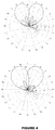
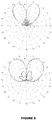
- Figure 4 show the azimuth and elevation patterns in low-band elements achieved by the new 3443443 architecture and cabling for 849 MHz and 761 MHz beams, respectively.
- an AFBN may be implemented with asymmetric weighting for the high-band antenna array elements. This would provide a higher cross over value compared to symmetrical weightings when applied for every group of eight patch antenna array elements.
- the directionality of the ABFN may also be reversed for every other group of high band antenna array elements to remove the frequency dispersion from the crossover point and to optimize the crossover value and SLL.
- Figure 5 shows an example of a conventional symmetrical ABFN design for high-band elements.
- two inputs see bottom of figure with leads labelled as 1 and 2 are fed to four outputs (see top of figure with leads labelled as 3 and 5 being derived from input lead 1 (directly from lead 1 and with a 90 degree phase shift from input lead 2) while leads labelled 4 and 6 are derived from input lead 2 (directly from lead 2 and with a 90 degree phase shift from input lead 1) to produce two beams.
- the weighting for leads 3 and 5 are symmetrical with the weighting for leads 4 and 6.
- the results for this conventional design are illustrated in the plots of Figure 5A .
- Figure 5B illustrates an ABFN design with asymmetrical weighting.
- input lead 1 still directly feeds output leads 5 and 3 (with a phase shift for the input from lead 2) while input lead 2 still directly feeds output leads 4 and 6 (with a phase shift for the input from lead 1) .
- the weighting for leads 5 and 3 no longer mirror the weighting for leads 4 and 6.
- This asymmetrical design includes an impedance transformation to provide a power divider with a one to ten power ratio for one of the outputs of a hybrid coupler.
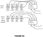
- FIG. 5C an architectural implementation of the novel ABFN asymmetrical weighting design is illustrated. As can be seen, the connections of the ABFN are reversed for every other group of high band elements to remove the frequency dispersion from the crossover point and to optimize the crossover value and SLL.
- rows 1 and 2 corresponds to one group of high band antenna array elements while rows 3 and 4 corresponds to another (and adjacent) group of high band antenna array elements.
- rows 3 and 4 corresponds to another (and adjacent) group of high band antenna array elements.
- the azimuth beamformer in Figure 5C would have two inputs -- one for the left beam and one for the right beam.
- Output leads 1 and 2 of the beamformer would feed the two leftmost columns for rows 1 and 2 while output leads 3 and 4 would feed the two rightmost columns for rows 1 and 2.
- output leads 1 and 2 would feed the two rightmost columns while output leads 3 and 4 would feed the two leftmost columns.
- the positions of the left and right input would be reversed from their positions for rows 1 and 2.
- asymmetrical weighting may be used for the AFBN in the 4 column rows in the 3443443 architecture with the directionality of the AFBN being switched between the first two rows of 4 columns and the second two rows of 4 columns.
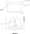
- Figure 6 show the azimuth plots of an implementation of an ABFN conventional design with symmetrical weightings for 2.17 and 1.71GHz.
- Figure 6 shows that an ABFN with symmetrical weightings produces dispersive crossover behavior for the two frequencies and also that the crossover value is low (around -14 dB to - 17dB).
- Figure 7 show azimuth plots for an ABFN design with using asymmetrical weightings. These plots are for implementations at 2.17 GHz and 1.71GHz. As can be seen from the plots, no dispersive crossover is visible, and an optimal crossover, namely at -11dB, is achieved for the full band pattern while providing very low SLL.
- Embodiment C listed above provides two high band antenna arrays and a single low band antenna array.
- the first high band antenna array is provided by the three leftmost columns of high band antenna array elements while the second high band antenna array is provided by the three rightmost columns of high band antenna array elements.
- Each high band antenna array has 30 high band antenna array elements divided into five groups of six elements per group.
- Each group has two rows of three antenna array elements per row. As can be seen, each group is longitudinally separated from adjacent groups by a distance d2 . Within each group, each row is separated from its adjacent row by a distance of d1. In this implementation, d2 is greater than d1.
- low band antenna array For the low band antenna array, seven rows of low band antenna array elements are present with the first two rows having three elements per row while the rest of the rows have only two elements per row. A distance c separates the first or top two rows of the low band array. For this implementation, a total of 16 low band antenna array elements were used.
- dipole antenna array elements were used for the low band array.
- patch antenna array elements were used for the high band antenna arrays.
- this embodiment the high-band and low-band arrays each have 33 degree bore sight beams.
- the configuration for this embodiment may be equally applied to 45 degree antennas, or other antennas with varying degrees of bore sight beams.
- FIG. 9 presented is a graphical representation of the azimuth pattern for the B-band of the antenna shown in Figure 8 with results simulated at 743 MHz and 860 MHz.
- FIG. 9A presented is a graphical representation of the azimuth pattern for the high-band beams of the antenna shown in FIGURE 8 simulated from 1.71 GHz to 2.36 GHz.
- the red line represents 1.71 GHz
- the purple line represents 1.85 GHz
- the blue line represents 1.94 GHz
- the maroon line represents 1.99 GHz
- the green line represents 2.045 GHz
- the pink line represents 2.17 GHz
- the teal line represents 2.36 GHz.
- FIG 10 presented is a front view schematic of an antenna system corresponding to Embodiment D listed above.
- this configuration produces six high band beams per polarization and three low band beams per polarization.
- the antenna system has 14 columns and 6 rows of high band antenna array elements along with 7 columns and 4 rows of low band antenna array elements. Both the longitudinal and latitudinal spacings for both the low band and high band arrays are non-uniform to improve the pattern quality.
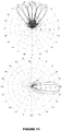
- Figure 11 shows the azimuth and elevation patterns for the antenna system illustrated in Figure 10 . These results were obtained at a low frequency band of 796 MHz and at a high frequency band 1940 MHz.
- Another possible embodiment produces five low frequency band beams and ten high frequency band beams.
- This embodiment would have 20 columns and 6 rows of high frequency band antenna array elements and 10 columns and 4 rows of low frequency band antenna array elements.
- the latitudinal and longitudinal spacings between antenna array elements are non-uniform.
Landscapes
- Physics & Mathematics (AREA)
- Electromagnetism (AREA)
- Engineering & Computer Science (AREA)
- Computer Networks & Wireless Communication (AREA)
- Variable-Direction Aerials And Aerial Arrays (AREA)
Claims (8)
- Système d'antennes (10) comprenant :- un premier réseau d'antennes comprenant une pluralité d'éléments de premier réseau d'antennes (20), ledit premier réseau d'antennes étant configuré pour être utilisé avec des signaux de bande basse fréquence ;- au moins un second réseau d'antennes comprenant une pluralité d'éléments de second réseau d'antennes (30), ledit au moins un second réseau d'antennes étant configuré pour être utilisé avec des signaux de bande haute fréquence ;
dans lequel- lesdits éléments de second réseau d'antennes (30) sont intercalés parmi lesdits éléments de premier réseau d'antennes (20) ;- lesdits éléments de premier réseau d'antennes (20) ont une première forme d'éléments de réseau d'antennes ;- lesdits éléments de second réseau d'antennes (30) ont une seconde forme d'éléments de réseau d'antennes ;- chaque élément de premier réseau d'antennes (20) est à une position différente de l'un quelconque desdits éléments de second réseau d'antennes (30) ;- chacun desdits éléments de premier réseau d'antennes (20) et chacun desdits éléments de second réseau d'antennes (30) est un élément d'antenne à bande simple,dans lequel lesdits éléments de second réseau d'antennes (30) sont divisés en une pluralité de groupes,
dans lequel chaque groupe d'éléments de second réseau d'antennes (30) est positionné longitudinalement entre des éléments desdits éléments de premier réseau d'antennes (20),
dans lequel chaque groupe d'éléments de second réseau d'antennes (30) est séparé longitudinalement de groupes adjacents par un premier espacement (d2) prédéterminé,
dans lequel au sein de chaque groupe d'éléments de second réseau d'antennes (30), chaque élément de second réseau d'antennes (30) est séparé longitudinalement d'éléments de second réseau d'antennes adjacents (30) par un second espacement (d1) prédéterminé,
dans lequel ledit premier espacement (d2) prédéterminé est supérieur audit second espacement (d1) prédéterminé, et
dans lequel ledit système d'antennes (10) est un réseau plan à la fois dans la bande basse fréquence et la bande haute fréquence, lesdits éléments de premier réseau d'antennes (20) sont des éléments de réseau d'antennes dipôle et lesdits éléments de second réseau d'antennes (30) sont des éléments de réseau d'antennes à plaque. - Système d'antennes (10) selon la revendication 1, dans lequel ledit premier réseau d'antennes comprend une pluralité de rangées desdits éléments de premier réseau d'antennes (20).
- Système d'antennes (10) selon l'une quelconque des revendications 1 à 2,
dans lequel au moins deux rangées desdits éléments de premier réseau d'antennes (20) ont différent nombres d'éléments de premier réseau d'antennes (20) par rangée. - Système d'antennes (10) selon la revendication 2, dans lequel ledit premier réseau d'antennes comprend l'un de :- sept rangées avec les première, quatrième et septième rangées ayant trois éléments de premier réseau d'antennes (20) et les deuxième, troisième, cinquième et sixième rangées ayant quatre éléments de premier réseau d'antennes (20) ; et- sept rangées, une première et une deuxième rangées desdits éléments de premier réseau d'antennes ayant trois colonnes et les troisième, quatrième, cinquième, sixième et septième rangées d'éléments de premier réseau d'antennes (20) ayant deux colonnes.
- Système d'antennes (10) selon la revendication 2, dans lequel les rangées desdits éléments de second réseau d'antennes (30) sont positionnées entre au moins deux rangées desdits éléments de premier réseau d'antennes (20).
- Système d'antenne selon l'une quelconque des revendications 1 à 5, dans lequel au moins un groupe d'éléments de réseau d'antennes à plaque est fourni depuis un côté arrière d'éléments de réseau d'antennes à plaque par un formeur de faisceaux intégré, et dans lequel ledit formeur de faisceaux intégré est utilisé pour supprimer une dispersion à partir d'un croisement et pour stabiliser un niveau dans les lobes latéraux de faisceaux produits par ledit système d'antennes.
- Système d'antennes (10) selon l'une quelconque des revendications 1 à 6,
dans lequel ledit système d'antennes (10) produit l'un de :- deux faisceaux de bande haute fréquence et un faisceau de bande basse fréquence de 33 degrés par polarisation ;- deux faisceaux de bande haute fréquence et un faisceau de bande basse fréquence de 45 degrés par polarisation ;- trois faisceaux de bande basse fréquence et six faisceaux de bande haute fréquence par polarisation ; et- cinq faisceaux de bande basse fréquence et dix faisceaux de bande haute fréquence. - Système d'antennes (10) selon l'une quelconque des revendications 1 à 7,
dans lequel le système d'antennes (10) possède l'un de :- 14 colonnes et 6 rangées d'éléments de réseau d'antennes de bande haute fréquence et 7 colonnes et 4 rangées d'éléments de réseau d'antennes de bande basse fréquence ; et- 20 colonnes et 6 rangées d'éléments de réseau d'antennes de bande haute fréquence et 10 colonnes et 4 rangées d'éléments de réseau d'antennes de bande basse fréquence.
Applications Claiming Priority (2)
| Application Number | Priority Date | Filing Date | Title |
|---|---|---|---|
| US201562166376P | 2015-05-26 | 2015-05-26 | |
| PCT/CA2016/050209 WO2016187701A1 (fr) | 2015-05-26 | 2016-02-29 | Architecture d'antenne de station de base multifaisceau et multibande simplifiée et sa mise en œuvre |
Publications (3)
| Publication Number | Publication Date |
|---|---|
| EP3304645A1 EP3304645A1 (fr) | 2018-04-11 |
| EP3304645A4 EP3304645A4 (fr) | 2018-12-05 |
| EP3304645B1 true EP3304645B1 (fr) | 2020-12-09 |
Family
ID=57392323
Family Applications (1)
| Application Number | Title | Priority Date | Filing Date |
|---|---|---|---|
| EP16798983.9A Active EP3304645B1 (fr) | 2015-05-26 | 2016-02-29 | Architecture d'antenne de station de base multifaisceau et multibande simplifiée et sa mise en uvre |
Country Status (4)
| Country | Link |
|---|---|
| US (1) | US11177565B2 (fr) |
| EP (1) | EP3304645B1 (fr) |
| CA (1) | CA2987084C (fr) |
| WO (1) | WO2016187701A1 (fr) |
Families Citing this family (17)
| Publication number | Priority date | Publication date | Assignee | Title |
|---|---|---|---|---|
| US10461438B2 (en) * | 2016-03-17 | 2019-10-29 | Communication Components Antenna Inc. | Wideband multi-level antenna element and antenna array |
| EP3460906B1 (fr) | 2017-09-20 | 2023-05-03 | Alcatel-Lucent Shanghai Bell Co., Ltd. | Antenne de réseau de télécommunication sans fil |
| WO2019068317A1 (fr) * | 2017-10-04 | 2019-04-11 | Huawei Technologies Co., Ltd. | Système d'antenne multibande |
| US10892553B2 (en) * | 2018-01-17 | 2021-01-12 | Kymeta Corporation | Broad tunable bandwidth radial line slot antenna |
| US11283195B2 (en) * | 2018-01-24 | 2022-03-22 | John Mezzalingua Associates, LLC | Fast rolloff antenna array face with heterogeneous antenna arrangement |
| CN109509995A (zh) * | 2018-12-28 | 2019-03-22 | 广东博纬通信科技有限公司 | 一种混合多波束天线 |
| CN109755759B (zh) * | 2019-01-04 | 2020-09-04 | 武汉虹信通信技术有限责任公司 | 一种多频窄波束天线阵列及天线 |
| WO2020159902A1 (fr) * | 2019-02-01 | 2020-08-06 | Commscope Technologies Llc | Antennes de station de base multibandes ayant des réseaux imbriqués |
| JP7361263B2 (ja) * | 2019-03-20 | 2023-10-16 | パナソニックIpマネジメント株式会社 | レーダ装置 |
| US11688947B2 (en) | 2019-06-28 | 2023-06-27 | RLSmith Holdings LLC | Radio frequency connectors, omni-directional WiFi antennas, omni-directional dual antennas for universal mobile telecommunications service, and related devices, systems, methods, and assemblies |
| CN112467403B (zh) * | 2019-09-06 | 2024-01-19 | 成都恪赛科技有限公司 | 一种适用于Sub 6G的双频共口径相控阵天线装置 |
| US11469520B2 (en) * | 2020-02-10 | 2022-10-11 | Raytheon Company | Dual band dipole radiator array |
| US11600922B2 (en) | 2020-02-10 | 2023-03-07 | Raytheon Company | Dual band frequency selective radiator array |
| US11245205B1 (en) | 2020-09-10 | 2022-02-08 | Integrity Microwave, LLC | Mobile multi-frequency RF antenna array with elevated GPS devices, systems, and methods |
| US20220102857A1 (en) * | 2020-09-29 | 2022-03-31 | T-Mobile Usa, Inc. | Multi-band millimeter wave (mmw) antenna arrays |
| CN114497993A (zh) * | 2020-11-13 | 2022-05-13 | 康普技术有限责任公司 | 辐射元件、天线组件以及基站天线 |
| CN115224535A (zh) * | 2021-04-15 | 2022-10-21 | 康普技术有限责任公司 | 连接装置和基站天线 |
Citations (3)
| Publication number | Priority date | Publication date | Assignee | Title |
|---|---|---|---|---|
| US5434580A (en) * | 1988-12-08 | 1995-07-18 | Alcatel Espace | Multifrequency array with composite radiators |
| US6529166B2 (en) * | 2000-09-22 | 2003-03-04 | Sarnoff Corporation | Ultra-wideband multi-beam adaptive antenna |
| US8354972B2 (en) * | 2007-06-06 | 2013-01-15 | Fractus, S.A. | Dual-polarized radiating element, dual-band dual-polarized antenna assembly and dual-polarized antenna array |
Family Cites Families (11)
| Publication number | Priority date | Publication date | Assignee | Title |
|---|---|---|---|---|
| US7053832B2 (en) * | 2002-07-03 | 2006-05-30 | Lucent Technologies Inc. | Multiband antenna arrangement |
| US7283101B2 (en) | 2003-06-26 | 2007-10-16 | Andrew Corporation | Antenna element, feed probe; dielectric spacer, antenna and method of communicating with a plurality of devices |
| US7817096B2 (en) * | 2003-06-16 | 2010-10-19 | Andrew Llc | Cellular antenna and systems and methods therefor |
| EP1908147B1 (fr) | 2005-07-22 | 2015-08-19 | Powerwave Technologies Sweden AB | Agencement d antennes avec des éléments d antenne entrelacés |
| US8437712B2 (en) * | 2005-10-27 | 2013-05-07 | Telecom Italia S.P.A. | Method and system for multiple antenna communications using multiple transmission modes, related apparatus and computer program product |
| CN103503231B (zh) * | 2011-05-02 | 2015-06-10 | 康普技术有限责任公司 | 三极子天线元件与天线阵列 |
| US9293809B2 (en) | 2011-06-30 | 2016-03-22 | Intel Corporation | Forty-five degree dual broad band base station antenna |
| US9472845B2 (en) * | 2011-12-15 | 2016-10-18 | Intel Corporation | Multiband 40 degree split beam antenna for wireless network |
| CN105122862B (zh) * | 2013-02-22 | 2018-12-11 | 昆特尔科技有限公司 | 多阵列天线 |
| US9711853B2 (en) * | 2013-08-07 | 2017-07-18 | Huawei Technologies Co., Ltd. | Broadband low-beam-coupling dual-beam phased array |
| CN103545621B (zh) * | 2013-10-25 | 2016-03-30 | 广东博纬通信科技有限公司 | 结构紧凑的多频段阵列天线 |
-
2016
- 2016-02-29 EP EP16798983.9A patent/EP3304645B1/fr active Active
- 2016-02-29 CA CA2987084A patent/CA2987084C/fr active Active
- 2016-02-29 US US15/576,763 patent/US11177565B2/en active Active
- 2016-02-29 WO PCT/CA2016/050209 patent/WO2016187701A1/fr active Application Filing
Patent Citations (3)
| Publication number | Priority date | Publication date | Assignee | Title |
|---|---|---|---|---|
| US5434580A (en) * | 1988-12-08 | 1995-07-18 | Alcatel Espace | Multifrequency array with composite radiators |
| US6529166B2 (en) * | 2000-09-22 | 2003-03-04 | Sarnoff Corporation | Ultra-wideband multi-beam adaptive antenna |
| US8354972B2 (en) * | 2007-06-06 | 2013-01-15 | Fractus, S.A. | Dual-polarized radiating element, dual-band dual-polarized antenna assembly and dual-polarized antenna array |
Also Published As
| Publication number | Publication date |
|---|---|
| WO2016187701A1 (fr) | 2016-12-01 |
| US11177565B2 (en) | 2021-11-16 |
| CA2987084C (fr) | 2023-01-24 |
| US20180301801A1 (en) | 2018-10-18 |
| EP3304645A4 (fr) | 2018-12-05 |
| EP3304645A1 (fr) | 2018-04-11 |
| CA2987084A1 (fr) | 2016-12-01 |
Similar Documents
| Publication | Publication Date | Title |
|---|---|---|
| EP3304645B1 (fr) | Architecture d'antenne de station de base multifaisceau et multibande simplifiée et sa mise en uvre | |
| US10804606B2 (en) | Broadband low-beam-coupling dual-beam phased array | |
| US11056773B2 (en) | Twin-beam base station antennas having thinned arrays with triangular sub-arrays | |
| US9871296B2 (en) | Mixed structure dual-band dual-beam three-column phased array antenna | |
| US11595827B2 (en) | Multi-beam base station antennas having wideband radiating elements | |
| US20150372397A1 (en) | An antenna arrangement and a base station | |
| US11515622B2 (en) | Base station antennas having multiband beam-former arrays and related methods of operation | |
| AU2014211633B2 (en) | An antenna arrangement and a base station | |
| US20150364832A1 (en) | An antenna arrangement and a base station | |
| US20180145400A1 (en) | Antenna | |
| US20210320399A1 (en) | Base station antennas having arrays of radiating elements with 4 ports without usage of diplexers | |
| US11069960B2 (en) | Multiband base station antennas having improved gain and/or interband isolation | |
| US20200328503A1 (en) | Base station antennas having arrays with frequency selective shared radiating elements | |
| US11581638B2 (en) | Dual-beam antenna array | |
| CN114520409A (zh) | 具有部分共享的宽带波束成形阵列的基站天线 | |
| US20220069462A1 (en) | Narrow mimo side-by-side arrays using complimentary array arrangement | |
| US20230006367A1 (en) | BASE STATION ANTENNAS INCLUDING SLANT +/- 45º AND H/V CROSS-DIPOLE RADIATING ELEMENTS THAT OPERATE IN THE SAME FREQUENCY BAND | |
| US20240162599A1 (en) | Base station antennas having f-style arrays that generate antenna beams having narrowed azimuth beamwidths | |
| WO2023154082A2 (fr) | Antennes de station de base mimo compactes qui génèrent des faisceaux d'antenne ayant des largeurs de faisceau d'azimut étroites | |
| CN116670930A (zh) | 具有弯曲辐射器臂的双波束基站天线 |
Legal Events
| Date | Code | Title | Description |
|---|---|---|---|
| STAA | Information on the status of an ep patent application or granted ep patent |
Free format text: STATUS: THE INTERNATIONAL PUBLICATION HAS BEEN MADE |
|
| PUAI | Public reference made under article 153(3) epc to a published international application that has entered the european phase |
Free format text: ORIGINAL CODE: 0009012 |
|
| STAA | Information on the status of an ep patent application or granted ep patent |
Free format text: STATUS: REQUEST FOR EXAMINATION WAS MADE |
|
| 17P | Request for examination filed |
Effective date: 20171122 |
|
| AK | Designated contracting states |
Kind code of ref document: A1 Designated state(s): AL AT BE BG CH CY CZ DE DK EE ES FI FR GB GR HR HU IE IS IT LI LT LU LV MC MK MT NL NO PL PT RO RS SE SI SK SM TR |
|
| AX | Request for extension of the european patent |
Extension state: BA ME |
|
| DAV | Request for validation of the european patent (deleted) | ||
| DAX | Request for extension of the european patent (deleted) | ||
| A4 | Supplementary search report drawn up and despatched |
Effective date: 20181106 |
|
| RIC1 | Information provided on ipc code assigned before grant |
Ipc: H01Q 1/24 20060101ALI20181029BHEP Ipc: H01Q 5/42 20150101AFI20181029BHEP Ipc: H01Q 5/40 20150101ALI20181029BHEP Ipc: H01Q 9/16 20060101ALI20181029BHEP Ipc: H01Q 5/307 20150101ALI20181029BHEP Ipc: H01Q 9/28 20060101ALI20181029BHEP Ipc: H01Q 5/48 20150101ALI20181029BHEP Ipc: H01Q 21/08 20060101ALN20181029BHEP Ipc: H01Q 21/12 20060101ALI20181029BHEP Ipc: H01Q 21/06 20060101ALI20181029BHEP Ipc: H01Q 9/04 20060101ALI20181029BHEP |
|
| STAA | Information on the status of an ep patent application or granted ep patent |
Free format text: STATUS: EXAMINATION IS IN PROGRESS |
|
| 17Q | First examination report despatched |
Effective date: 20190822 |
|
| RIC1 | Information provided on ipc code assigned before grant |
Ipc: H01Q 5/40 20150101ALI20200525BHEP Ipc: H01Q 5/42 20150101AFI20200525BHEP Ipc: H01Q 5/307 20150101ALI20200525BHEP Ipc: H01Q 21/08 20060101ALN20200525BHEP Ipc: H01Q 5/48 20150101ALI20200525BHEP Ipc: H01Q 21/06 20060101ALI20200525BHEP Ipc: H01Q 9/16 20060101ALI20200525BHEP Ipc: H01Q 1/24 20060101ALI20200525BHEP Ipc: H01Q 21/12 20060101ALI20200525BHEP Ipc: H01Q 9/28 20060101ALI20200525BHEP Ipc: H01Q 9/04 20060101ALI20200525BHEP |
|
| GRAP | Despatch of communication of intention to grant a patent |
Free format text: ORIGINAL CODE: EPIDOSNIGR1 |
|
| STAA | Information on the status of an ep patent application or granted ep patent |
Free format text: STATUS: GRANT OF PATENT IS INTENDED |
|
| RIC1 | Information provided on ipc code assigned before grant |
Ipc: H01Q 5/42 20150101AFI20200610BHEP Ipc: H01Q 5/307 20150101ALI20200610BHEP Ipc: H01Q 5/48 20150101ALI20200610BHEP Ipc: H01Q 21/06 20060101ALI20200610BHEP Ipc: H01Q 9/16 20060101ALI20200610BHEP Ipc: H01Q 21/12 20060101ALI20200610BHEP Ipc: H01Q 9/28 20060101ALI20200610BHEP Ipc: H01Q 1/24 20060101ALI20200610BHEP Ipc: H01Q 21/08 20060101ALN20200610BHEP Ipc: H01Q 9/04 20060101ALI20200610BHEP Ipc: H01Q 5/40 20150101ALI20200610BHEP |
|
| RIC1 | Information provided on ipc code assigned before grant |
Ipc: H01Q 21/08 20060101ALN20200629BHEP Ipc: H01Q 9/04 20060101ALI20200629BHEP Ipc: H01Q 5/40 20150101ALI20200629BHEP Ipc: H01Q 9/16 20060101ALI20200629BHEP Ipc: H01Q 21/06 20060101ALI20200629BHEP Ipc: H01Q 9/28 20060101ALI20200629BHEP Ipc: H01Q 1/24 20060101ALI20200629BHEP Ipc: H01Q 5/42 20150101AFI20200629BHEP Ipc: H01Q 21/12 20060101ALI20200629BHEP Ipc: H01Q 5/307 20150101ALI20200629BHEP Ipc: H01Q 5/48 20150101ALI20200629BHEP |
|
| INTG | Intention to grant announced |
Effective date: 20200714 |
|
| GRAS | Grant fee paid |
Free format text: ORIGINAL CODE: EPIDOSNIGR3 |
|
| GRAA | (expected) grant |
Free format text: ORIGINAL CODE: 0009210 |
|
| STAA | Information on the status of an ep patent application or granted ep patent |
Free format text: STATUS: THE PATENT HAS BEEN GRANTED |
|
| AK | Designated contracting states |
Kind code of ref document: B1 Designated state(s): AL AT BE BG CH CY CZ DE DK EE ES FI FR GB GR HR HU IE IS IT LI LT LU LV MC MK MT NL NO PL PT RO RS SE SI SK SM TR |
|
| REG | Reference to a national code |
Ref country code: GB Ref legal event code: FG4D |
|
| REG | Reference to a national code |
Ref country code: AT Ref legal event code: REF Ref document number: 1344338 Country of ref document: AT Kind code of ref document: T Effective date: 20201215 Ref country code: CH Ref legal event code: EP |
|
| REG | Reference to a national code |
Ref country code: DE Ref legal event code: R096 Ref document number: 602016049522 Country of ref document: DE |
|
| REG | Reference to a national code |
Ref country code: IE Ref legal event code: FG4D |
|
| PG25 | Lapsed in a contracting state [announced via postgrant information from national office to epo] |
Ref country code: NO Free format text: LAPSE BECAUSE OF FAILURE TO SUBMIT A TRANSLATION OF THE DESCRIPTION OR TO PAY THE FEE WITHIN THE PRESCRIBED TIME-LIMIT Effective date: 20210309 Ref country code: RS Free format text: LAPSE BECAUSE OF FAILURE TO SUBMIT A TRANSLATION OF THE DESCRIPTION OR TO PAY THE FEE WITHIN THE PRESCRIBED TIME-LIMIT Effective date: 20201209 Ref country code: FI Free format text: LAPSE BECAUSE OF FAILURE TO SUBMIT A TRANSLATION OF THE DESCRIPTION OR TO PAY THE FEE WITHIN THE PRESCRIBED TIME-LIMIT Effective date: 20201209 Ref country code: GR Free format text: LAPSE BECAUSE OF FAILURE TO SUBMIT A TRANSLATION OF THE DESCRIPTION OR TO PAY THE FEE WITHIN THE PRESCRIBED TIME-LIMIT Effective date: 20210310 |
|
| REG | Reference to a national code |
Ref country code: AT Ref legal event code: MK05 Ref document number: 1344338 Country of ref document: AT Kind code of ref document: T Effective date: 20201209 |
|
| PG25 | Lapsed in a contracting state [announced via postgrant information from national office to epo] |
Ref country code: BG Free format text: LAPSE BECAUSE OF FAILURE TO SUBMIT A TRANSLATION OF THE DESCRIPTION OR TO PAY THE FEE WITHIN THE PRESCRIBED TIME-LIMIT Effective date: 20210309 Ref country code: LV Free format text: LAPSE BECAUSE OF FAILURE TO SUBMIT A TRANSLATION OF THE DESCRIPTION OR TO PAY THE FEE WITHIN THE PRESCRIBED TIME-LIMIT Effective date: 20201209 Ref country code: SE Free format text: LAPSE BECAUSE OF FAILURE TO SUBMIT A TRANSLATION OF THE DESCRIPTION OR TO PAY THE FEE WITHIN THE PRESCRIBED TIME-LIMIT Effective date: 20201209 |
|
| REG | Reference to a national code |
Ref country code: NL Ref legal event code: MP Effective date: 20201209 |
|
| PG25 | Lapsed in a contracting state [announced via postgrant information from national office to epo] |
Ref country code: NL Free format text: LAPSE BECAUSE OF FAILURE TO SUBMIT A TRANSLATION OF THE DESCRIPTION OR TO PAY THE FEE WITHIN THE PRESCRIBED TIME-LIMIT Effective date: 20201209 Ref country code: HR Free format text: LAPSE BECAUSE OF FAILURE TO SUBMIT A TRANSLATION OF THE DESCRIPTION OR TO PAY THE FEE WITHIN THE PRESCRIBED TIME-LIMIT Effective date: 20201209 |
|
| REG | Reference to a national code |
Ref country code: LT Ref legal event code: MG9D |
|
| PG25 | Lapsed in a contracting state [announced via postgrant information from national office to epo] |
Ref country code: SM Free format text: LAPSE BECAUSE OF FAILURE TO SUBMIT A TRANSLATION OF THE DESCRIPTION OR TO PAY THE FEE WITHIN THE PRESCRIBED TIME-LIMIT Effective date: 20201209 Ref country code: LT Free format text: LAPSE BECAUSE OF FAILURE TO SUBMIT A TRANSLATION OF THE DESCRIPTION OR TO PAY THE FEE WITHIN THE PRESCRIBED TIME-LIMIT Effective date: 20201209 Ref country code: EE Free format text: LAPSE BECAUSE OF FAILURE TO SUBMIT A TRANSLATION OF THE DESCRIPTION OR TO PAY THE FEE WITHIN THE PRESCRIBED TIME-LIMIT Effective date: 20201209 Ref country code: CZ Free format text: LAPSE BECAUSE OF FAILURE TO SUBMIT A TRANSLATION OF THE DESCRIPTION OR TO PAY THE FEE WITHIN THE PRESCRIBED TIME-LIMIT Effective date: 20201209 Ref country code: SK Free format text: LAPSE BECAUSE OF FAILURE TO SUBMIT A TRANSLATION OF THE DESCRIPTION OR TO PAY THE FEE WITHIN THE PRESCRIBED TIME-LIMIT Effective date: 20201209 Ref country code: PT Free format text: LAPSE BECAUSE OF FAILURE TO SUBMIT A TRANSLATION OF THE DESCRIPTION OR TO PAY THE FEE WITHIN THE PRESCRIBED TIME-LIMIT Effective date: 20210409 Ref country code: RO Free format text: LAPSE BECAUSE OF FAILURE TO SUBMIT A TRANSLATION OF THE DESCRIPTION OR TO PAY THE FEE WITHIN THE PRESCRIBED TIME-LIMIT Effective date: 20201209 |
|
| PG25 | Lapsed in a contracting state [announced via postgrant information from national office to epo] |
Ref country code: AT Free format text: LAPSE BECAUSE OF FAILURE TO SUBMIT A TRANSLATION OF THE DESCRIPTION OR TO PAY THE FEE WITHIN THE PRESCRIBED TIME-LIMIT Effective date: 20201209 Ref country code: PL Free format text: LAPSE BECAUSE OF FAILURE TO SUBMIT A TRANSLATION OF THE DESCRIPTION OR TO PAY THE FEE WITHIN THE PRESCRIBED TIME-LIMIT Effective date: 20201209 |
|
| REG | Reference to a national code |
Ref country code: DE Ref legal event code: R097 Ref document number: 602016049522 Country of ref document: DE |
|
| PG25 | Lapsed in a contracting state [announced via postgrant information from national office to epo] |
Ref country code: IS Free format text: LAPSE BECAUSE OF FAILURE TO SUBMIT A TRANSLATION OF THE DESCRIPTION OR TO PAY THE FEE WITHIN THE PRESCRIBED TIME-LIMIT Effective date: 20210409 Ref country code: MC Free format text: LAPSE BECAUSE OF FAILURE TO SUBMIT A TRANSLATION OF THE DESCRIPTION OR TO PAY THE FEE WITHIN THE PRESCRIBED TIME-LIMIT Effective date: 20201209 |
|
| PLBE | No opposition filed within time limit |
Free format text: ORIGINAL CODE: 0009261 |
|
| STAA | Information on the status of an ep patent application or granted ep patent |
Free format text: STATUS: NO OPPOSITION FILED WITHIN TIME LIMIT |
|
| REG | Reference to a national code |
Ref country code: BE Ref legal event code: MM Effective date: 20210228 |
|
| PG25 | Lapsed in a contracting state [announced via postgrant information from national office to epo] |
Ref country code: LU Free format text: LAPSE BECAUSE OF NON-PAYMENT OF DUE FEES Effective date: 20210228 Ref country code: LI Free format text: LAPSE BECAUSE OF NON-PAYMENT OF DUE FEES Effective date: 20210228 Ref country code: CH Free format text: LAPSE BECAUSE OF NON-PAYMENT OF DUE FEES Effective date: 20210228 Ref country code: AL Free format text: LAPSE BECAUSE OF FAILURE TO SUBMIT A TRANSLATION OF THE DESCRIPTION OR TO PAY THE FEE WITHIN THE PRESCRIBED TIME-LIMIT Effective date: 20201209 Ref country code: IT Free format text: LAPSE BECAUSE OF FAILURE TO SUBMIT A TRANSLATION OF THE DESCRIPTION OR TO PAY THE FEE WITHIN THE PRESCRIBED TIME-LIMIT Effective date: 20201209 |
|
| 26N | No opposition filed |
Effective date: 20210910 |
|
| PG25 | Lapsed in a contracting state [announced via postgrant information from national office to epo] |
Ref country code: SI Free format text: LAPSE BECAUSE OF FAILURE TO SUBMIT A TRANSLATION OF THE DESCRIPTION OR TO PAY THE FEE WITHIN THE PRESCRIBED TIME-LIMIT Effective date: 20201209 Ref country code: DK Free format text: LAPSE BECAUSE OF FAILURE TO SUBMIT A TRANSLATION OF THE DESCRIPTION OR TO PAY THE FEE WITHIN THE PRESCRIBED TIME-LIMIT Effective date: 20201209 |
|
| PG25 | Lapsed in a contracting state [announced via postgrant information from national office to epo] |
Ref country code: IE Free format text: LAPSE BECAUSE OF NON-PAYMENT OF DUE FEES Effective date: 20210228 Ref country code: ES Free format text: LAPSE BECAUSE OF FAILURE TO SUBMIT A TRANSLATION OF THE DESCRIPTION OR TO PAY THE FEE WITHIN THE PRESCRIBED TIME-LIMIT Effective date: 20201209 |
|
| PG25 | Lapsed in a contracting state [announced via postgrant information from national office to epo] |
Ref country code: IS Free format text: LAPSE BECAUSE OF FAILURE TO SUBMIT A TRANSLATION OF THE DESCRIPTION OR TO PAY THE FEE WITHIN THE PRESCRIBED TIME-LIMIT Effective date: 20210409 |
|
| PG25 | Lapsed in a contracting state [announced via postgrant information from national office to epo] |
Ref country code: BE Free format text: LAPSE BECAUSE OF NON-PAYMENT OF DUE FEES Effective date: 20210228 |
|
| PGFP | Annual fee paid to national office [announced via postgrant information from national office to epo] |
Ref country code: FR Payment date: 20230221 Year of fee payment: 8 |
|
| PG25 | Lapsed in a contracting state [announced via postgrant information from national office to epo] |
Ref country code: CY Free format text: LAPSE BECAUSE OF FAILURE TO SUBMIT A TRANSLATION OF THE DESCRIPTION OR TO PAY THE FEE WITHIN THE PRESCRIBED TIME-LIMIT Effective date: 20201209 |
|
| PG25 | Lapsed in a contracting state [announced via postgrant information from national office to epo] |
Ref country code: HU Free format text: LAPSE BECAUSE OF FAILURE TO SUBMIT A TRANSLATION OF THE DESCRIPTION OR TO PAY THE FEE WITHIN THE PRESCRIBED TIME-LIMIT; INVALID AB INITIO Effective date: 20160229 |
|
| PG25 | Lapsed in a contracting state [announced via postgrant information from national office to epo] |
Ref country code: MK Free format text: LAPSE BECAUSE OF FAILURE TO SUBMIT A TRANSLATION OF THE DESCRIPTION OR TO PAY THE FEE WITHIN THE PRESCRIBED TIME-LIMIT Effective date: 20201209 |
|
| PGFP | Annual fee paid to national office [announced via postgrant information from national office to epo] |
Ref country code: DE Payment date: 20240228 Year of fee payment: 9 Ref country code: GB Payment date: 20240228 Year of fee payment: 9 |