EP3304246B1 - Adaptive vorrichtung und verfahren zur leistungsversorgung - Google Patents
Adaptive vorrichtung und verfahren zur leistungsversorgung Download PDFInfo
- Publication number
- EP3304246B1 EP3304246B1 EP16724641.2A EP16724641A EP3304246B1 EP 3304246 B1 EP3304246 B1 EP 3304246B1 EP 16724641 A EP16724641 A EP 16724641A EP 3304246 B1 EP3304246 B1 EP 3304246B1
- Authority
- EP
- European Patent Office
- Prior art keywords
- power
- budget
- receiving device
- allotted
- providing device
- Prior art date
- Legal status (The legal status is an assumption and is not a legal conclusion. Google has not performed a legal analysis and makes no representation as to the accuracy of the status listed.)
- Active
Links
Images


Classifications
-
- G—PHYSICS
- G06—COMPUTING OR CALCULATING; COUNTING
- G06F—ELECTRIC DIGITAL DATA PROCESSING
- G06F1/00—Details not covered by groups G06F3/00 - G06F13/00 and G06F21/00
- G06F1/26—Power supply means, e.g. regulation thereof
- G06F1/32—Means for saving power
- G06F1/3203—Power management, i.e. event-based initiation of a power-saving mode
- G06F1/3234—Power saving characterised by the action undertaken
- G06F1/3287—Power saving characterised by the action undertaken by switching off individual functional units in the computer system
-
- G—PHYSICS
- G06—COMPUTING OR CALCULATING; COUNTING
- G06F—ELECTRIC DIGITAL DATA PROCESSING
- G06F1/00—Details not covered by groups G06F3/00 - G06F13/00 and G06F21/00
- G06F1/26—Power supply means, e.g. regulation thereof
- G06F1/266—Arrangements to supply power to external peripherals either directly from the computer or under computer control, e.g. supply of power through the communication port, computer controlled power-strips
-
- G—PHYSICS
- G06—COMPUTING OR CALCULATING; COUNTING
- G06F—ELECTRIC DIGITAL DATA PROCESSING
- G06F1/00—Details not covered by groups G06F3/00 - G06F13/00 and G06F21/00
- G06F1/26—Power supply means, e.g. regulation thereof
- G06F1/32—Means for saving power
- G06F1/3203—Power management, i.e. event-based initiation of a power-saving mode
- G06F1/3206—Monitoring of events, devices or parameters that trigger a change in power modality
-
- H—ELECTRICITY
- H04—ELECTRIC COMMUNICATION TECHNIQUE
- H04L—TRANSMISSION OF DIGITAL INFORMATION, e.g. TELEGRAPHIC COMMUNICATION
- H04L12/00—Data switching networks
- H04L12/02—Details
- H04L12/10—Current supply arrangements
-
- G—PHYSICS
- G06—COMPUTING OR CALCULATING; COUNTING
- G06F—ELECTRIC DIGITAL DATA PROCESSING
- G06F1/00—Details not covered by groups G06F3/00 - G06F13/00 and G06F21/00
- G06F1/26—Power supply means, e.g. regulation thereof
-
- G—PHYSICS
- G06—COMPUTING OR CALCULATING; COUNTING
- G06F—ELECTRIC DIGITAL DATA PROCESSING
- G06F1/00—Details not covered by groups G06F3/00 - G06F13/00 and G06F21/00
- G06F1/26—Power supply means, e.g. regulation thereof
- G06F1/28—Supervision thereof, e.g. detecting power-supply failure by out of limits supervision
-
- H—ELECTRICITY
- H02—GENERATION; CONVERSION OR DISTRIBUTION OF ELECTRIC POWER
- H02J—CIRCUIT ARRANGEMENTS OR SYSTEMS FOR SUPPLYING OR DISTRIBUTING ELECTRIC POWER; SYSTEMS FOR STORING ELECTRIC ENERGY
- H02J1/00—Circuit arrangements for DC mains or DC distribution networks
- H02J1/14—Balancing the load in a network
-
- H02J4/25—
Definitions
- the present invention relates to an adaptive power providing device and a method for adaptively providing power to multiple power receiving devices.
- US 7,650,519 B1 describes a system and methods for connecting a graphic user interface to a powered network.
- the network-powered graphic user interface system converts encoded computer user interface signals transmitted over a powered network cable to multiple signal sets, each set associated with a peripheral device interface. Methods for managing the admission of the peripheral devices are also described. Connection criteria include the power budget for the connection, device characteristics, device power requirements and the characteristics of other devices sharing the powered network connection.
- US 2008/052546 A1 discloses a method which includes monitoring power drawn by powered devices, each having a respective policing limit. If power drawn by one of the powered devices exceeds the policing limit, it is determined if a power budget of the power sourcing equipment has been exceeded. If the power budget has not been exceeded, the power sourcing equipment continues to provide power to the powered devices. If the power budget has been exceeded, actions such as sending or logging a warning, requesting the powered device to reduce its power requirement, or removing power from one of the powered devices, are initiated at the power sourcing equipment.
- PoE Power over Ethernet
- PSE Power Sourcing Equipment
- PD Powered Device
- a possible process for this may have the steps of an controlled inrush (after a connection is provided by inserting a cable or the like), where the allocated power budget corresponds to the initially maximum possible power, of a maximal power consumption (after the PD started up) of the PD, with the PSE measuring the (maximum) power consumption, and finally of a reallocation of the power budget by the PSE for the PD based on the measure maximum power consumption (e.g. calculated by adding a margin accommodating for fluctuations of power requirements and measurement variations or errors).
- Such autoclass approach allows, in comparison to the conventional power classes provided by PoE, for a finer granularity in the allocation of power and therefore for an improved power management.
- Typical examples for PDs where this can happen are robotic systems where, for example, wear in the gear or aging grease increases moving resistance and subsequently the required power for the electrical drive. In lighting applications, a drop in LED efficiency and reduced optical quality of the luminaire may lead to increase input power need.
- a PD which needs more power than classed during its classification cycle will get switched off whenever its power drawn is above the overpower threshold the PSE has memorized.
- the PSE will reclass the PD before it gets powered on again. For lamps in lighting applications this would mean that they would be turned off at a certain moment in time. As long as there is sufficient power budget reserve available the lamp can be restarted but an unpleasant flicker will irritate users of the illuminated space.
- a power providing device arranged for providing power to multiple power receiving devices
- the power providing device is a power source equipment and arranged to provide the power by power over Ethernet a power negotiation unit configured to detect a power receiving device and to perform a power negotiation with the power receiving device, a power monitoring unit configured to monitor the power consumption of each power receiving device, and a power control unit configured to at least temporarily suspend power provision to a power receiving device in case the power consumption of said power receiving device exceeds a power budget allotted in the power negotiation to said power receiving device, wherein the power control unit is further configured increase the power budget allotted to said power receiving device in response to the power consumption of said power receiving device exceeding a predetermined consumption threshold value.
- a method of providing power by a power providing device to multiple power receiving devices comprising a power negotiation step of detecting a power receiving device and performing a power negotiation between the power providing device and the power receiving device, a power monitoring step by the power providing device of monitoring the power consumption of each power receiving device, and a power suspension step by the power providing device of at least temporarily suspending power provision to a power receiving device in case the power consumption of said power receiving device exceeds a power budget allotted in the power negotiation to said power receiving device, the method further comprising a budget adjustment step by the power providing device of increasing the power budget allotted to said power receiving device in response to the power consumption of said power receiving device exceeding a predetermined consumption threshold value.
- the present invention provides for a "dynamic power class" mechanism in a PSE (as an example of a power providing device) is constantly adjusting the budgeted power with monitored power of the PD (as an example of the power receiving device). In this way, typical reasons for increased maximum power consumption of power receiving devices can be accommodated without intermediate power off cycling.
- the power control unit is configured to increase the power budget only in case a total of power budgets allotted to the multiple power receiving devices is less than a total of power providable by the power providing device to the multiple power receiving devices.
- the sum of all allotted power budgets should preferably not exceed the total available power.
- the power control unit is arranged for determining, based on a rate of change of the power consumption of said power receiving device and a difference between the total of power budgets allotted to the multiple power receiving devices and the total of power providable by the power providing device to the multiple power receiving devices, a time during which the power budget may be increased, wherein the power providing device further comprises an output unit for outputting a signal indicative of said determined time.
- the user may take steps for replacing, for example, power receiving devices showing an increased power demand at a suitable time before the power limit is reached.
- the power control unit is arranged for reducing a power budget allotted to at least one different power receiving device upon or prior to increasing the power budget allotted to said power receiving device.
- the dynamic approach on power budgets allows also for temporarily reducing another allotted power budget, which at a later point in time may be (again) increased.
- the power control unit is configured to increase the power budget only in case a rate of change of the power consumption of said power receiving device is less that a predetermined rate threshold value.
- a change in the power consumption beyond a certain rate of change may be indicative of a malfunction, in which situation preferably there is no increase in the allotted power budget provided.
- the power control unit is arranged for determining a difference between an original power budget of a power receiving device and the increased power budget, wherein the power providing device further comprises an output unit for outputting a signal indicative of said difference exceeding a predetermined difference threshold value.
- the difference threshold value may be used as a means for indicating a certain amount of deterioration or the like at the power receiving device causing the increased power demand.
- the power control unit is arranged for determining a difference between an original power budget of a power receiving device and the increased power budget, wherein the power control unit is configured to increase the power budget only in case the difference between the original power budget and the increased power budget is less than a predetermined range value, the predetermined range value being set either in absolute terms or based on a ratio of the original power budget.
- the increase of the power budget is allowed only in case a total of power budgets allotted to the multiple power receiving devices is less than a total of power providable by the power providing device to the multiple power receiving devices, only in case a rate of change of the power consumption of said power receiving device is less that a predetermined rate threshold value, and/or only in case the difference between the original power budget and the increased power budget is less than a predetermined range value, the predetermined range value being set either in absolute terms or based on ratio of the original power budget, when the power control unit is not allowed to increase the power budget, the power control unit is, in addition to at least temporarily suspending power provision to a power receiving device, further configured to provide a signal indicative of the power control unit being not allowed to increase the power budget.
- the power providing device Preferably before the suspension of the power provision takes place, the power providing device according to this embodiment indicates, e.g. by means of a data signal, by sound and/or by light, that an adjustment of the power budget is not possible and that therefore an exceeding of the allotted power budget may be expected in the future.
- the power control unit is arranged, in response to a request and/or upon meeting a predetermined condition, for setting the power budgets allotted to at least two of the multiple power receiving devices based on a respective current power consumption of said power receiving devices.
- a re-setting or re-allotting of a number of power budgets allows for redistributing the totally available power prior to the adjustment of the particular allotted power budget.
- the power providing device further comprises a memory, wherein the power control unit is configured to store information related to increasing the power budget into the memory.
- a software product for controlling the provision of power from a power providing device to multiple power receiving devices comprising code means for causing a power providing device according to the invention to carry out the step of the method according to the invention.
- the power providing device arranged for providing power to multiple power receiving devices of claim 1 the method of providing power by a power providing device to multiple power receiving devices of claim 11, and the computer program of claim 12 have similar and/or identical preferred embodiments, in particular, as defined in the dependent claims.
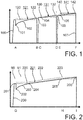
- Fig. 1 shows a development over time in accordance with conventional allocation of power budgets, including reclassification with powering down, in a case of Power over Ethernet.
- the ordinate indicates power and the abscissa indicates time.
- Line 100 shows the power consumption by the PD or the power provided by the PSE:
- the PSE detects the maximal power 120 to be consumed by the PD and adds a margin 121 on top of it leading to the overpower threshold value 122, resulting in the allotted power budget.
- the PD when switched on 101 is consuming an increasing amount of power 102 over an extended time period (not drawn to scale).
- the PSE deactivates the related port and starts a new negotiation cycle (during this cycle a PD being a lamp would be off and the related space not illuminated).
- the PD now can use "Autoclass" to signal a higher required amount of power 130. Again the margin 131 is added leading to the new overpower threshold value 132 or allotted power budget.
- the PD gets powered again 104 (position C in the time line).
- position C position in the time line
- the PSE deactivates and so on. This may go on (following position E in the time line) until no budget for more power is available (position 107) (position F in the time line) when after the overpower switch off no new negotiation starts or no negotiation succeeds if alternatively a negotiation is initiated by the PSE but as budget is exhausted it is not leading to repowering the PD.
- Fig. 2 shows a development over time in accordance with an embodiment of the invention.
- the start of the development of the power consumption by the PD or the power provision by the PSE corresponds to the discussion above and the case of Fig. 1 , i.e. as in normal "Autoclass" PoE systems.
- a power budget is initialized at a value 222, corresponding to the "autopower" value presented by the PD in the pulse level 201 before with an added margin 221.
- a power consumption threshold value 220 is set.
- the power initial consumption is set to the previously measure maximal initial power consumption 201, even though a different setting is also possible.
- the PD draws an initial power 202 after classification has been finalized.
- the PD power demand slowly increases (as shown by 203) and reaches (in average) the originally set consumption threshold value 220 at point 204, the budget and the consumption threshold value (maintaining a constant margin to the budget) grow in line with the power demand.
- the consumption threshold value 220 is provided with a constant margin 221 to the allotted power budget 222, this is not necessarily the case in all embodiments of the invention.
- the consumption threshold value may also be a fixed portion of the allotted power budget (i.e. maintaining the ratio between consumption threshold value and power budget) or may also come closer to the allotted power budget over time.
- detection means that the current monitoring which is also used by the PSE to watch about over currents is used for observing any changes in PD power consumption. So the power is estimated by looking at the current only and estimating that the voltage at the PD is not changing.
- the power budget is set at a value that keeps sufficient margin for any noise in measurements as well as in PD current ripple.
- Fig. 3 shows a schematic representation of a Power Sourcing Equipment in accordance with an embodiment of the invention.
- Fig. 3 shows a PoE PSE 2 according to the present invention as an example of a power providing device, including an incoming line 1 for receiving power from mains and a number of connecting lines 6 to PDs 3.
- a power negotiation unit is not shown.
- the PSE includes a mains power supply 21 feeding the PSE ports 23 through port control means 22.
- This unit 22 - as an example of a portion of a power control unit - has per port 23 an isolation switch 291-29n and a current measurement means 281-28n.
- the current measured is used in a PSE-PI power monitor 25 (as an example of a power monitoring unit) to detect - in particular - consistently increasing power usage of a PD and modify a PSE port power budget list 24 (an example of a memory) accordingly.
- the information in this list is used by a PSE PI overload protection system 26 - as an example of a further portion of a power control unit - in order switching of ports 23 (or PDs 3) which take more power than the budgeted power.
- the mechanism described here is using the margin between an allotted power budget and the originally determined maximum power consumption not only for the original intended use which was noise in current measurement and ripple in the PD current.
- the margin is used for adjusting the budget whenever the PD is consistently using more power than budgeted and hence makes consistently use of the margin.
- Fig. 4 shows a schematic representation of a Power Sourcing Equipment in accordance with another embodiment of the invention.
- the power providing device 2' is provided in the form of a power sourcing equipment in accordance with Power over Ethernet.
- the PSE 2' in connected to a power source (not shown) and receives power at an internal power supply 31.
- the power supply 31 (the control of which per se is not shown or discussed here) is connected to ports 33 of the PSE, to which powered devices (not shown; examples of power receiving devices) can be connected.
- the PSE 2 includes a power monitoring unit 35 which is arranged to monitor the power provided by the power supply 31 to each port 33.
- the power monitoring unit 35 includes means for detecting the current drawn by each PD connected to a respective port 33.
- a power control unit 32 which is provided with switches for selectively interrupting the connection between the power supply 31 and each port 33. It is to be noted that a control of the power supply to a respective port may also be provided in any other manner in accordance with providing power to power receiving devices. The skilled person is sufficiently familiar with such measure, so no further explanation thereof is needed.
- the PSE 2' additionally includes a power negotiation unit 37, coupled to the connection to the ports 33, so to be arranged for performing power negotiation with PDs connected to the ports 33.
- a power negotiation unit 37 coupled to the connection to the ports 33, so to be arranged for performing power negotiation with PDs connected to the ports 33.
- the power negotiation unit 37 is coupled to a memory 34 and stores therein the results of the power negotiation, such that the respective power budgets and consumption threshold values can be checked by the power control unit 32.
- the consumption threshold values may be set by the power negotiation unit 37 or they may be set by other means, e.g. by the power control unit 32.
- the power monitoring unit 35 monitors the power consumption of the respective PDs and informs the power control unit 32 accordingly.
- the power control unit 32 compares the respective power consumption with the consumption threshold value.
- the power control unit 32 checks whether it is possible to increase the allotted power budget, e.g. checks whether the current total available power is more than the currently provided or allotted power.
- the power control unit 32 checks whether the increase in power consumption should be considered anomalous, e.g. whether the rate of increase is beyond a rate threshold value, which might be indicative of, for example, a short circuit situation.
- the power control unit 32 checks whether an adjustment of the allotted power budget may exceed an allowable range based on an originally set or allotted power budget of the PD.
- the power control unit 32 modifies the entry in the memory 34 as to the allotted power budget for the respective PD or port 33.
- the power control unit 32 causes an output unit 38 to indicate such situation to the outside, e.g. to the user of the PSE 2'.
- the power control unit 32 checks for whether the power consumption of a PDs (or port 33) exceeds the respective allotted power budget. If there is over-consumption, the power control unit 32 provides that the power supply to the port 33 is at least temporarily interrupted or stopped altogether (until a next power negotiation).
- Fig. 5 shows a flow diagram illustrating a process according to an embodiment of the invention.
- a PoE power budget management is provided. Following after this, in monitoring step 902, it is checked whether the (for example, average) power consumption at a certain port exceeds a consumption threshold value.
- step 902 If there is no excess consumption, the flow returns to step 902, forming a loop.
- a comparison step 904 If there is excess consumption, it is checked, in a comparison step 904, whether the currently allotted total power budget allows for increasing the budget allotted to the port or PD showing excess consumption. Depending on the outcome of this check, in branching step 906, the flow either goes to suspending step 907 or to adjustment step 908. In suspending step 907, it is checked whether not only the consumption threshold value is exceeded but also the allotted power budget. If the power budget is also exceeded, the provision of power to the PD is suspended, at least for a certain amount of time. If the allotted power budget is not exceeded, the process may return to step 902.
- step 908 the allotted power budget and the consumption threshold value are adjusted and the flow returns to step 902.
- the present invention includes a process of deciding whether or not following with the power budged the average draw power.
- the process as explained above is executed for each port of the PSE.
- a consistently taking higher power than a limit close the allotted budget is detected.
- the average (or peak) power is compared to the available budget reserves. If there is sufficient reserve it gets adjusted to a new value. If no sufficiently reserve is found, the allotted budget is kept. If the power drawn is above budget (including the margin discussed above) the PD gets switched off by the over power process not shown here.
- Fig. 6 shows a flow diagram illustrating a process according to another embodiment of the invention.
- the process starts with a power negotiation step 1001 of detecting a PD as a power receiving device and performing a power negotiation between a PSE as a power providing device and the PD.
- step 1002 it is checked whether there is a request and whether a predetermined condition is met and depending on the outcome of such check, the power budgets allotted to at least two of the PDs are newly allotted based on a respective current power consumption of said PDs in a first reallottment step 1003, after which the process returns to step 1002.
- step 1004 the PSE monitors the power consumption of the coupled PDs.
- a first comparison step 1005 the consumed power is compared with a consumption threshold value. If the consumed power is less than the threshold value, the process returns to step 1002.
- a rate of change of the power consumption of respective PD is compared with a predetermined rate threshold value. If the threshold is exceeded, indicating a unusual increase in power consumption possibly caused by a malfunction, the process is taken to indication step 1007. Otherwise, the next step is a third comparison step 1008, where, after determining a difference between an original power budget of the PD and a possibly increased power budget (or the currently increased power budget), this difference is compared with a predetermined range value like 5 W.
- the predetermined range value is set in absolute terms, even though other ways of setting or predetermining may also be used, e.g. setting based on a ratio of the original power budget. In case the difference is too large, the next step would be step 1007, otherwise the process continues with a forth comparison step 1009.
- the fourth comparison step 1009 the difference between the original power budget of the PD and the increased or current power budget is checked and a signal indicative of said difference exceeding a predetermined difference threshold value is outputted in case.
- a fifth comparison step 1010 it is checked whether a total of power budgets allotted to the multiple PDs is less than a total of power providable by the PSE to the multiple PDs (i.e. whether currently an increased allotted power budget is possible at all). In case no adjustment appears possible based on the currently allotted power budgets, in a second reallotment step 1011, is attempted to reduce a power budget allotted to at least one different PD. If successful, the flow continues to an adjustment step 1012, otherwise the flow continues to step 1007.
- indication step 1007 it is indicated to the user of the PSE, that an adjustment of the allotted power budget is not possible.
- the power supply to the PD is (temporarily) suspended or stopped in a suspending step 1015 (followed by conventional over load processing) or the process returns to step 1002.
- the allotted power budget and the consumption threshold value are adjusted.
- a time is determining or estimated, during which the power budget for the particular PD may be increased, whereafter a signal indicative of said determined or estimated time is outputted, after which step the process returns to step 1002.
- the classification in the context of Power over Ethernet or the like is not provided following the autoclass approach as discussed for IEEE 802.3bt but according to the conventional power classes.
- the allocation of the budget is provided by "jumping" to the next higher class (as long as there is sufficient total power available).
- this method may probably only be used when a PD has identified to be in one of the 802.3bt classes (currently discussed as type 3 and 4 classes).
- a communication protocol LLDP (or a similar protocol) may be used, so commands can be issued by the power receiving device(s) in order to reset the (ever growing) budget to the actual power drawn, in this way power budgets can be swapped under the control of (a) power receiving device(s).
- the power providing device may request the power receiving device to step back to a lower power level and after that reduce the actual budget. This allows for a dynamic power budget control by the power providing device.
- a further sophisticated system may allow a central (e.g. lighting) controller to monitor the adjustments in order to warn the building management of an aging power receiving device which might need to be serviced or replaced.
- a power providing device may even be able sending related alert messages whenever substantial grows of input power shows up at any power receiving device.
- a particular further embodiment of the invention provides a Power over Ethernet PSE which detects at its PoE plugs (PSE PI) power drawn by the PD and adjusts the related port power budget if the drawn power consistently grows over time, thereby avoiding overpower switch-off.
- the PSE dynamically may step up the power class to the next higher class.
- the overpower threshold may be adjusted to higher values keeping always a fixed margin compared to the average power observed. It is possible that the rest budget is used to determine whether further grows is possible.
- the actual power budget may be reset to a certain value. The value may be written via network commands. The value may be taken from actual (or averaged) power drawn by the related PD.
- a load (PD) may request to reset the budget to a new value.
- PDs connected to the network like a building control system
- the PD may be informed to reduce input power before a reset of budget action is initiated.
- the actual budget may be read through network commands by e.g. the building control system. Changes of the budget may be signaled towards a central node, e.g. the building control system.
- a single processor, device or other unit may fulfill the functions of several items recited in the claims.
- the mere fact that certain measures are recited in mutually different dependent claims does not indicate that a combination of these measures cannot be used to advantage.
- Operations like detecting a power receiving device, performing power negotiation, monitoring power consumption, suspending power provision, increasing a power budget, and further operation, management and diagnostics steps can be implemented as program code means of a computer program and/or as dedicated hardware.
- a computer program may be stored and/or distributed on a suitable medium, such as an optical storage medium or a solid-state medium, supplied together with or as part of other hardware, but may also be distributed in other forms, such as via the Internet or other wired or wireless telecommunication systems.
- a suitable medium such as an optical storage medium or a solid-state medium, supplied together with or as part of other hardware, but may also be distributed in other forms, such as via the Internet or other wired or wireless telecommunication systems.
Landscapes
- Engineering & Computer Science (AREA)
- Theoretical Computer Science (AREA)
- General Engineering & Computer Science (AREA)
- Physics & Mathematics (AREA)
- General Physics & Mathematics (AREA)
- Computer Hardware Design (AREA)
- Signal Processing (AREA)
- Computer Networks & Wireless Communication (AREA)
- Computing Systems (AREA)
- Power Engineering (AREA)
- Supply And Distribution Of Alternating Current (AREA)
- Remote Monitoring And Control Of Power-Distribution Networks (AREA)
- Power Sources (AREA)
Claims (11)
- Leistungsversorgungsvorrichtung (2, 2'), welche angeordnet ist, um mehrere Leistung empfangende Vorrichtungen (3) mit Leistung zu versorgen, wobei die Leistungsversorgungsvorrichtung (2, 2') ein Stromquellengerät ist, welches angeordnet ist, die Leistung über Power-over-Ethernet bereitzustellen und umfasst:- eine Leistungsvermittlungseinheit (37), welche konfiguriert ist, eine Leistung empfangende Vorrichtung (3) aus den mehreren Leistung empfangenden Vorrichtung (3) zu erkennen und eine Leistungsvermittlung mit der Leistung empfangenden Vorrichtung (3) durchzuführen,- eine Leistungsüberwachungseinheit (25, 35), welche konfiguriert ist, um den Leistungsverbrauch (203) von jeder der Leistung empfangenden Vorrichtungen (3) zu überwachen, und- eine Leistungssteuerungseinheit (22, 26, 32), welche konfiguriert ist, als Reaktion darauf, dass der Leistungsverbrauch (203) der Leistung empfangenden Vorrichtung (3) einen vorbestimmten Verbrauchsschwellenwert (220) übersteigt, ein Leistungsbudget (222) zu erhöhen, welches in der Leistungsvermittlung der Leistung empfangenden Vorrichtung (3) zugewiesen ist;
wobei der Verbrauchsschwellenwert (220)- mit einer konstanten Grenze (221) zu dem zugewiesenen Leistungsbudget (222) versehen ist; oder- ein fester Teil des zugewiesenen Leistungsbudgets (222) ist; oder- mit der Zeit dem zugewiesenen Leistungsbudget (222) näher kommt;wobei die Leistungssteuerungseinheit (22, 26, 32) weiter konfiguriert ist, um zumindest vorübergehend Leistungsbereitstellung an die Leistung empfangende Vorrichtung (3) auszusetzen, falls der Leistungsverbrauch (203) der Leistung empfangenden Vorrichtung (3) das Leistungsbudget (222) übersteigt;
wobei die Leistungssteuerungseinheit (22, 26, 32) konfiguriert ist, um das Leistungsbudget (222) nur zu erhöhen, falls eine Änderungsrate des Leistungsverbrauchs (203) der Leistung empfangenden Vorrichtung (3) kleiner ist als ein vorbestimmter Ratenschwellenwert. - Leistungsversorgungsvorrichtung (2, 2') nach Anspruch 1,
wobei die Leistungssteuerungseinheit (22, 26, 32) konfiguriert ist, um das Leistungsbudget (222) nur weiter zu erhöhen, falls: ein Gesamtwert der Leistungsbudgets, welche den mehreren Leistung empfangenden Vorrichtungen (3) zugewiesen sind, kleiner ist als ein Gesamtwert der für die mehreren Leistung empfangenden Vorrichtungen (3) von den Leistungsversorgungsvorrichtungen (2, 2') bereitstellbaren Leistung. - Leistungsversorgungsvorrichtung (2') nach Anspruch 2,
wobei die Leistungssteuerungseinheit (32) angeordnet ist, auf Basis einer Änderungsrate des Leistungsverbrauchs (203) der Leistung empfangenden Vorrichtung (3) und einer Differenz zwischen dem Gesamtwert der den mehreren Leistung empfangenden Vorrichtungen (3) zugewiesenen Leistungsbudgets und dem Gesamtwert der von der Leistungsversorgungsvorrichtung (2') für die mehreren Leistung empfangenden Vorrichtung (3) bereitstellbaren Leistung, eine Zeit zu bestimmen, während der das Leistungsbudget (222) erhöht werden kann,
wobei die Leistungsversorgungsvorrichtung (2') weiter eine Ausgabeeinheit (38) zur Ausgabe eines Signals umfasst, welches die bestimmte Zeit angibt. - Leistungsversorgungsvorrichtung (2, 2') nach Anspruch 1,
wobei die Leistungssteuerungseinheit (22, 26, 32) angeordnet ist, um bei oder vor dem Erhöhen des Leistungsbudgets (222), welches der Leistung empfangenden Vorrichtung (3) zugewiesen ist, ein Leistungsbudget (222) zu verringern, welches zumindest einer anderen Leistung empfangenden Vorrichtung (3) zugewiesen ist. - Leistungsversorgungsvorrichtung (2') nach Anspruch 1,
wobei die Leistungssteuerungseinheit (32) angeordnet ist, um eine Differenz zwischen einem ursprünglichen Leistungsbudget einer Leistung empfangenden Vorrichtung (3) und dem erhöhten Leistungsbudget (222) zu bestimmen, wobei die Leistungsversorgungsvorrichtung (2') weiter eine Ausgabeeinheit (38) umfasst, um ein Signal auszugeben, welches die Differenz angibt, welche einen vorbestimmten Differenzschwellenwert übersteigt. - Leistungsversorgungsvorrichtung (2, 2') nach Anspruch 1,
wobei die Leistungssteuerungseinheit (22, 26, 32) angeordnet ist, um einen Differenz zwischen einem ursprünglichen Leistungsbudget einer Leistung empfangenden Vorrichtung (3) und dem erhöhten Leistungsbudget (222) zu bestimmen,
wobei die Leistungssteuerungseinheit (22, 26, 32) konfiguriert ist, um das Leistungsbudget (222) nur weiter zu erhöhen, falls: die Differenz zwischen dem ursprünglichen Leistungsbudget und dem erhöhten Leistungsbudget (222) kleiner ist als ein vorbestimmter Bereichswert, wobei der vorbestimmte Bereichswerts entweder in absoluten Zahlen oder auf Basis eines Verhältnisses zu dem ursprünglichen Leistungsbudget festgelegt wird. - Leistungsversorgungsvorrichtung (2, 2') nach Anspruch 1, 2 oder 7,
wobei, wenn die Leistungssteuerungseinheit (22, 26, 32) das Leistungsbudget (222) nicht erhöhen darf, die Leistungssteuerungseinheit (22, 26, 32) zusätzlich zu zumindest vorübergehendem Aussetzen von Leistungsbereitstellung für eine Leistung empfangenden Vorrichtung (3) weiter konfiguriert ist, um ein Signal bereitzustellen, welches angibt, dass die Leistungssteuerungseinheit (22, 26, 32) das Leistungsbudget (222) nicht erhöhen darf. - Leistungsversorgungsvorrichtung (2, 2') nach Anspruch 1,
wobei die Leistungssteuerungseinheit (22, 26, 32) angeordnet ist, um als Reaktion auf eine Anfrage und/oder bei Erfüllen einer vorbestimmten Bedingung die Leistungsbudgets (222), welche zumindest zwei von den mehreren Leistung empfangenden Vorrichtungen (3) zugewiesen sind, auf Basis eines entsprechenden aktuellen Leistungsverbrauchs (203) der Leistung empfangenden Vorrichtungen (3) festzulegen. - Leistungsversorgungsvorrichtung (2, 2') nach Anspruch 1, weiter umfassend:- einen Speicher (24, 34),wobei die Leistungssteuerungseinheit (22, 26, 34) konfiguriert ist, um Informationen in Bezug auf Erhöhen des Leistungsbudgets (222) in den Speicher (24, 34) zu speichern.
- Verfahren zur Bereitstellung von Leistung durch eine Leistungsversorgungsvorrichtung (2, 2') für mehrere Leistung empfangende Vorrichtungen (3), wobei die Leistungsversorgungsvorrichtung (2, 2') ein Stromquellengerät ist, welches angeordnet ist, die Leistung über Power-over-Ethernet bereitzustellen wobei das Verfahren folgende Schritte umfasst:- einen Leistungsvermittlungsschritt (900, 1001) des Erkennens einer Leistung empfangende Vorrichtung (3) aus den mehreren Leistung empfangenden Vorrichtung (3) und des Durchführens einer Leistungsvermittlung zwischen Leistungsversorgungsvorrichtung (2, 2') und der Leistung empfangenden Vorrichtung (3),- einen Leistungsüberwachungsschritt (902, 1004), durch die Leistungsversorgungsvorrichtung(2, 2'), des Überwachens des Leistungsverbrauchs (203) jeder der Leistung empfangenden Vorrichtungen (3), und- wobei das Verfahren weiter einen Budgetanpassungsschritt (908, 1012), durch die Leistungsversorgungsvorrichtung (2, 2'), des Erhöhens als Reaktion darauf umfasst, dass der Leistungsverbrauch (203) der Leistung empfangenden Vorrichtung (3) einen vorbestimmten Verbrauchsschwellenwert (220) übersteigt, eines Leistungsbudgets (222), welches in der Leistungsvermittlung der Leistung empfangenden Vorrichtung (3) zugewiesen ist;
wobei der Verbrauchsschwellenwert (220)- mit einer konstanten Grenze (221) zu dem zugewiesenen Leistungsbudget (222) versehen ist; oder- ein fester Teil des zugewiesenen Leistungsbudgets (222) ist; oder- mit der Zeit dem zugewiesenen Leistungsbudget (222) näher kommt;- einen Leistungsaussetzungsschritt (907, 1015), durch die Leistungsversorgungsvorrichtung (2, 2'), des zumindest vorübergehenden Aussetzens der Leistungsbereitstellung für die Leistung empfangende Vorrichtung (3), falls der Leistungsverbrauch (203) der Leistung empfangenden Vorrichtung (3) ein Leistungsbudget (222) übersteigt, welches in der Leistungsvermittlung der Leistung empfangenden Vorrichtung (3) zugewiesen ist,wobei die Leistungssteuerungseinheit (22, 26, 32) konfiguriert ist, um das Leistungsbudget (222) nur zu erhöhen, falls eine Änderungsrate des Leistungsverbrauchs (203) der Leistung empfangenden Vorrichtung (3) kleiner ist als ein vorbestimmter Ratenschwellenwert. - Softwareprodukt zur Steuerung der Bereitstellung von Leistung aus einer Leistungsversorgungsvorrichtung (2, 2') an mehrere Leistung empfangende Vorrichtungen (3), wobei das Softwareprodukt Codemittel umfasst, um die Leistungsversorgungsvorrichtung (2, 2') nach Anspruch 1 zu veranlassen, den Schritt des Verfahrens nach Anspruch 10 auszuführen.
Applications Claiming Priority (2)
| Application Number | Priority Date | Filing Date | Title |
|---|---|---|---|
| EP15169178 | 2015-05-26 | ||
| PCT/EP2016/061699 WO2016189002A1 (en) | 2015-05-26 | 2016-05-24 | Adaptive power providing device and method for providing power |
Publications (2)
| Publication Number | Publication Date |
|---|---|
| EP3304246A1 EP3304246A1 (de) | 2018-04-11 |
| EP3304246B1 true EP3304246B1 (de) | 2020-05-13 |
Family
ID=53268703
Family Applications (1)
| Application Number | Title | Priority Date | Filing Date |
|---|---|---|---|
| EP16724641.2A Active EP3304246B1 (de) | 2015-05-26 | 2016-05-24 | Adaptive vorrichtung und verfahren zur leistungsversorgung |
Country Status (5)
| Country | Link |
|---|---|
| US (1) | US10671146B2 (de) |
| EP (1) | EP3304246B1 (de) |
| JP (1) | JP6918708B2 (de) |
| CN (1) | CN107850926B (de) |
| WO (1) | WO2016189002A1 (de) |
Families Citing this family (20)
| Publication number | Priority date | Publication date | Assignee | Title |
|---|---|---|---|---|
| US9900164B2 (en) * | 2015-06-10 | 2018-02-20 | Cisco Technology, Inc. | Dynamic power management |
| EP3338402B1 (de) * | 2015-08-20 | 2019-01-23 | Philips Lighting Holding B.V. | Leistungsbereitstellungsvorrichtung und verfahren |
| US10996729B2 (en) * | 2016-07-12 | 2021-05-04 | Hewlett-Packard Development Company, L.P. | Balancing a power load among USB ports |
| US10630494B2 (en) * | 2017-12-15 | 2020-04-21 | Crestron Electronics, Inc. | PoE powered device with link layer startup processor |
| US10790997B2 (en) | 2019-01-23 | 2020-09-29 | Cisco Technology, Inc. | Transmission of pulse power and data in a communications network |
| US11061456B2 (en) | 2019-01-23 | 2021-07-13 | Cisco Technology, Inc. | Transmission of pulse power and data over a wire pair |
| US11456883B2 (en) | 2019-03-13 | 2022-09-27 | Cisco Technology, Inc. | Multiple phase pulse power in a network communications system |
| GB2583752A (en) * | 2019-05-09 | 2020-11-11 | Canon Kk | Device and method for power supply control |
| US11159335B2 (en) * | 2019-08-06 | 2021-10-26 | Cisco Technology, Inc. | Controller-based management of noncompliant power over ethernet devices |
| CN110519068B (zh) * | 2019-08-15 | 2022-05-03 | 普联技术有限公司 | 一种poe供电控制装置和poe供电系统 |
| US12126399B2 (en) | 2019-11-01 | 2024-10-22 | Cisco Technology, Inc. | Fault managed power with dynamic and adaptive fault sensor |
| US11063630B2 (en) | 2019-11-01 | 2021-07-13 | Cisco Technology, Inc. | Initialization and synchronization for pulse power in a network system |
| US11991787B2 (en) * | 2020-09-21 | 2024-05-21 | Cisco Technology, Inc. | Dynamic access point radio frequency power control for power over Ethernet adaptation |
| US11445439B1 (en) * | 2021-03-01 | 2022-09-13 | Charter Communications Operating, Llc | Managing power over ethernet through a switch |
| CN113125877B (zh) * | 2021-03-02 | 2022-12-06 | 华为技术有限公司 | 一种受电设备pd检测设备 |
| CN113220091A (zh) * | 2021-05-31 | 2021-08-06 | 北京比特大陆科技有限公司 | 超算设备、算力板的在位检测方法及存储介质 |
| CN115550081A (zh) * | 2021-06-30 | 2022-12-30 | 华为技术有限公司 | 一种供电设备的功率管理方法和装置 |
| CN113777425B (zh) * | 2021-08-24 | 2024-03-29 | 上海超丰科技有限公司 | 以太网供电系统的分级检测方法及供电设备 |
| US12095575B2 (en) * | 2022-03-30 | 2024-09-17 | International Business Machines Corporation | Vehicle and power management using power over ethernet devices |
| US12524337B2 (en) * | 2023-09-29 | 2026-01-13 | Sk Hynix Nand Product Solutions Corp. | Host-controlled dynamic power management for memory devices |
Citations (1)
| Publication number | Priority date | Publication date | Assignee | Title |
|---|---|---|---|---|
| US20080052546A1 (en) * | 2006-08-25 | 2008-02-28 | Cisco Technology, Inc. | Inline power policing |
Family Cites Families (13)
| Publication number | Priority date | Publication date | Assignee | Title |
|---|---|---|---|---|
| US5884086A (en) | 1997-04-15 | 1999-03-16 | International Business Machines Corporation | System and method for voltage switching to supply various voltages and power levels to a peripheral device |
| US7612470B2 (en) * | 1999-01-12 | 2009-11-03 | Microsemi Corp.—Analog Mixed Signal Group Ltd. | System for providing power over Ethernet through a patch panel |
| US7441133B2 (en) * | 2002-10-15 | 2008-10-21 | Microsemi Corp. - Analog Mixed Signal Group Ltd. | Rack level power management for power over Ethernet |
| US7240224B1 (en) * | 2003-08-29 | 2007-07-03 | Cisco Technology, Inc. | Inline power based device communications |
| EP1571745A1 (de) * | 2004-03-01 | 2005-09-07 | Alcatel | Verfahren zur Steuerung des Leistungsverbrauchs |
| US7509505B2 (en) * | 2005-01-04 | 2009-03-24 | Cisco Technology, Inc. | Method and system for managing power delivery for power over Ethernet systems |
| JP4764696B2 (ja) | 2005-10-07 | 2011-09-07 | ルネサスエレクトロニクス株式会社 | 半導体集積回路装置 |
| US7650519B1 (en) | 2005-10-12 | 2010-01-19 | Teradici Corporation | Methods and apparatus for managing a user interface on a powered network |
| WO2007070193A1 (en) * | 2005-12-12 | 2007-06-21 | Linear Technology Corporation | Integrated powered device connector in system for supplying power over communication link |
| US8250381B2 (en) * | 2007-03-30 | 2012-08-21 | Brocade Communications Systems, Inc. | Managing power allocation to ethernet ports in the absence of mutually exclusive detection and powering cycles in hardware |
| US7996690B2 (en) * | 2008-01-24 | 2011-08-09 | Dell Products L.P. | System and method for dynamic utilization-based power allocation in a modular information handling system |
| US9656567B2 (en) | 2012-03-15 | 2017-05-23 | Chargepoint, Inc. | Electric vehicle charging station dynamically responding to power limit messages based on a recent history of power provided |
| US9897981B2 (en) * | 2013-10-01 | 2018-02-20 | Linear Technology Corporation | Detection and classification scheme for power over ethernet system |
-
2016
- 2016-05-24 EP EP16724641.2A patent/EP3304246B1/de active Active
- 2016-05-24 CN CN201680030469.7A patent/CN107850926B/zh active Active
- 2016-05-24 US US15/576,301 patent/US10671146B2/en active Active
- 2016-05-24 WO PCT/EP2016/061699 patent/WO2016189002A1/en not_active Ceased
- 2016-05-24 JP JP2017560927A patent/JP6918708B2/ja active Active
Patent Citations (1)
| Publication number | Priority date | Publication date | Assignee | Title |
|---|---|---|---|---|
| US20080052546A1 (en) * | 2006-08-25 | 2008-02-28 | Cisco Technology, Inc. | Inline power policing |
Non-Patent Citations (1)
| Title |
|---|
| GALIT MENDELSON: "White Paper All You Need To Know About Power over Ethernet (PoE) and the IEEE 802.3af Standard", 1 June 2004 (2004-06-01), XP055120330, Retrieved from the Internet <URL:http://ww.babcockinc.com/documents/powerdsine/whitepapers/PoE_and_IEEE802_3af.pdf> [retrieved on 20140527] * |
Also Published As
| Publication number | Publication date |
|---|---|
| CN107850926A (zh) | 2018-03-27 |
| CN107850926B (zh) | 2021-09-07 |
| EP3304246A1 (de) | 2018-04-11 |
| JP6918708B2 (ja) | 2021-08-11 |
| WO2016189002A1 (en) | 2016-12-01 |
| US10671146B2 (en) | 2020-06-02 |
| JP2018516058A (ja) | 2018-06-14 |
| US20180150127A1 (en) | 2018-05-31 |
Similar Documents
| Publication | Publication Date | Title |
|---|---|---|
| EP3304246B1 (de) | Adaptive vorrichtung und verfahren zur leistungsversorgung | |
| US8694817B2 (en) | System bus with variable output power supply | |
| CN107431640B (zh) | 受电装置、供电设备装置、以太网供电网络系统及其方法 | |
| US10756910B2 (en) | Dynamic power management | |
| US11349676B2 (en) | Power providing device and method, power receiving device | |
| CN105684348B (zh) | 受电设备和包含受电设备的配电系统 | |
| US10412799B2 (en) | Powered device and power distribution system comprising the powered device | |
| JP4981686B2 (ja) | 通信リンクを介して電力を供給するためのシステムにおける高電力フォールドバックメカニズム | |
| US20080219289A1 (en) | 10GBase-T link speed arbitration for 30m transceivers | |
| WO2016142152A1 (en) | Powered device in power-over-ethernet network system, and methods therefore | |
| JP6693002B1 (ja) | 電力ネゴシエーション中の即時起動のための電力管理デバイス | |
| TWI448882B (zh) | 減低乙太網路供電之保護頻帶 |
Legal Events
| Date | Code | Title | Description |
|---|---|---|---|
| STAA | Information on the status of an ep patent application or granted ep patent |
Free format text: STATUS: THE INTERNATIONAL PUBLICATION HAS BEEN MADE |
|
| PUAI | Public reference made under article 153(3) epc to a published international application that has entered the european phase |
Free format text: ORIGINAL CODE: 0009012 |
|
| STAA | Information on the status of an ep patent application or granted ep patent |
Free format text: STATUS: REQUEST FOR EXAMINATION WAS MADE |
|
| 17P | Request for examination filed |
Effective date: 20180102 |
|
| AK | Designated contracting states |
Kind code of ref document: A1 Designated state(s): AL AT BE BG CH CY CZ DE DK EE ES FI FR GB GR HR HU IE IS IT LI LT LU LV MC MK MT NL NO PL PT RO RS SE SI SK SM TR |
|
| AX | Request for extension of the european patent |
Extension state: BA ME |
|
| DAV | Request for validation of the european patent (deleted) | ||
| DAX | Request for extension of the european patent (deleted) | ||
| RAP1 | Party data changed (applicant data changed or rights of an application transferred) |
Owner name: PHILIPS LIGHTING HOLDING B.V. |
|
| RAP1 | Party data changed (applicant data changed or rights of an application transferred) |
Owner name: SIGNIFY HOLDING B.V. |
|
| STAA | Information on the status of an ep patent application or granted ep patent |
Free format text: STATUS: EXAMINATION IS IN PROGRESS |
|
| 17Q | First examination report despatched |
Effective date: 20190404 |
|
| REG | Reference to a national code |
Ref country code: DE Ref legal event code: R079 Ref document number: 602016036360 Country of ref document: DE Free format text: PREVIOUS MAIN CLASS: G06F0001260000 Ipc: H02J0005000000 |
|
| RIC1 | Information provided on ipc code assigned before grant |
Ipc: H02J 5/00 20160101AFI20191031BHEP Ipc: H02J 1/14 20060101ALI20191031BHEP Ipc: H04L 12/10 20060101ALI20191031BHEP |
|
| GRAP | Despatch of communication of intention to grant a patent |
Free format text: ORIGINAL CODE: EPIDOSNIGR1 |
|
| STAA | Information on the status of an ep patent application or granted ep patent |
Free format text: STATUS: GRANT OF PATENT IS INTENDED |
|
| INTG | Intention to grant announced |
Effective date: 20191209 |
|
| GRAS | Grant fee paid |
Free format text: ORIGINAL CODE: EPIDOSNIGR3 |
|
| GRAA | (expected) grant |
Free format text: ORIGINAL CODE: 0009210 |
|
| STAA | Information on the status of an ep patent application or granted ep patent |
Free format text: STATUS: THE PATENT HAS BEEN GRANTED |
|
| AK | Designated contracting states |
Kind code of ref document: B1 Designated state(s): AL AT BE BG CH CY CZ DE DK EE ES FI FR GB GR HR HU IE IS IT LI LT LU LV MC MK MT NL NO PL PT RO RS SE SI SK SM TR |
|
| REG | Reference to a national code |
Ref country code: GB Ref legal event code: FG4D |
|
| REG | Reference to a national code |
Ref country code: CH Ref legal event code: EP |
|
| REG | Reference to a national code |
Ref country code: DE Ref legal event code: R096 Ref document number: 602016036360 Country of ref document: DE |
|
| REG | Reference to a national code |
Ref country code: AT Ref legal event code: REF Ref document number: 1271520 Country of ref document: AT Kind code of ref document: T Effective date: 20200615 |
|
| REG | Reference to a national code |
Ref country code: LT Ref legal event code: MG4D |
|
| REG | Reference to a national code |
Ref country code: NL Ref legal event code: MP Effective date: 20200513 |
|
| PG25 | Lapsed in a contracting state [announced via postgrant information from national office to epo] |
Ref country code: LT Free format text: LAPSE BECAUSE OF FAILURE TO SUBMIT A TRANSLATION OF THE DESCRIPTION OR TO PAY THE FEE WITHIN THE PRESCRIBED TIME-LIMIT Effective date: 20200513 Ref country code: GR Free format text: LAPSE BECAUSE OF FAILURE TO SUBMIT A TRANSLATION OF THE DESCRIPTION OR TO PAY THE FEE WITHIN THE PRESCRIBED TIME-LIMIT Effective date: 20200814 Ref country code: SE Free format text: LAPSE BECAUSE OF FAILURE TO SUBMIT A TRANSLATION OF THE DESCRIPTION OR TO PAY THE FEE WITHIN THE PRESCRIBED TIME-LIMIT Effective date: 20200513 Ref country code: PT Free format text: LAPSE BECAUSE OF FAILURE TO SUBMIT A TRANSLATION OF THE DESCRIPTION OR TO PAY THE FEE WITHIN THE PRESCRIBED TIME-LIMIT Effective date: 20200914 Ref country code: IS Free format text: LAPSE BECAUSE OF FAILURE TO SUBMIT A TRANSLATION OF THE DESCRIPTION OR TO PAY THE FEE WITHIN THE PRESCRIBED TIME-LIMIT Effective date: 20200913 Ref country code: NO Free format text: LAPSE BECAUSE OF FAILURE TO SUBMIT A TRANSLATION OF THE DESCRIPTION OR TO PAY THE FEE WITHIN THE PRESCRIBED TIME-LIMIT Effective date: 20200813 Ref country code: FI Free format text: LAPSE BECAUSE OF FAILURE TO SUBMIT A TRANSLATION OF THE DESCRIPTION OR TO PAY THE FEE WITHIN THE PRESCRIBED TIME-LIMIT Effective date: 20200513 |
|
| PG25 | Lapsed in a contracting state [announced via postgrant information from national office to epo] |
Ref country code: RS Free format text: LAPSE BECAUSE OF FAILURE TO SUBMIT A TRANSLATION OF THE DESCRIPTION OR TO PAY THE FEE WITHIN THE PRESCRIBED TIME-LIMIT Effective date: 20200513 Ref country code: HR Free format text: LAPSE BECAUSE OF FAILURE TO SUBMIT A TRANSLATION OF THE DESCRIPTION OR TO PAY THE FEE WITHIN THE PRESCRIBED TIME-LIMIT Effective date: 20200513 Ref country code: BG Free format text: LAPSE BECAUSE OF FAILURE TO SUBMIT A TRANSLATION OF THE DESCRIPTION OR TO PAY THE FEE WITHIN THE PRESCRIBED TIME-LIMIT Effective date: 20200813 Ref country code: LV Free format text: LAPSE BECAUSE OF FAILURE TO SUBMIT A TRANSLATION OF THE DESCRIPTION OR TO PAY THE FEE WITHIN THE PRESCRIBED TIME-LIMIT Effective date: 20200513 |
|
| REG | Reference to a national code |
Ref country code: AT Ref legal event code: MK05 Ref document number: 1271520 Country of ref document: AT Kind code of ref document: T Effective date: 20200513 |
|
| PG25 | Lapsed in a contracting state [announced via postgrant information from national office to epo] |
Ref country code: AL Free format text: LAPSE BECAUSE OF FAILURE TO SUBMIT A TRANSLATION OF THE DESCRIPTION OR TO PAY THE FEE WITHIN THE PRESCRIBED TIME-LIMIT Effective date: 20200513 Ref country code: NL Free format text: LAPSE BECAUSE OF FAILURE TO SUBMIT A TRANSLATION OF THE DESCRIPTION OR TO PAY THE FEE WITHIN THE PRESCRIBED TIME-LIMIT Effective date: 20200513 |
|
| PG25 | Lapsed in a contracting state [announced via postgrant information from national office to epo] |
Ref country code: RO Free format text: LAPSE BECAUSE OF FAILURE TO SUBMIT A TRANSLATION OF THE DESCRIPTION OR TO PAY THE FEE WITHIN THE PRESCRIBED TIME-LIMIT Effective date: 20200513 Ref country code: CZ Free format text: LAPSE BECAUSE OF FAILURE TO SUBMIT A TRANSLATION OF THE DESCRIPTION OR TO PAY THE FEE WITHIN THE PRESCRIBED TIME-LIMIT Effective date: 20200513 Ref country code: ES Free format text: LAPSE BECAUSE OF FAILURE TO SUBMIT A TRANSLATION OF THE DESCRIPTION OR TO PAY THE FEE WITHIN THE PRESCRIBED TIME-LIMIT Effective date: 20200513 Ref country code: EE Free format text: LAPSE BECAUSE OF FAILURE TO SUBMIT A TRANSLATION OF THE DESCRIPTION OR TO PAY THE FEE WITHIN THE PRESCRIBED TIME-LIMIT Effective date: 20200513 Ref country code: SM Free format text: LAPSE BECAUSE OF FAILURE TO SUBMIT A TRANSLATION OF THE DESCRIPTION OR TO PAY THE FEE WITHIN THE PRESCRIBED TIME-LIMIT Effective date: 20200513 Ref country code: AT Free format text: LAPSE BECAUSE OF FAILURE TO SUBMIT A TRANSLATION OF THE DESCRIPTION OR TO PAY THE FEE WITHIN THE PRESCRIBED TIME-LIMIT Effective date: 20200513 Ref country code: CH Free format text: LAPSE BECAUSE OF NON-PAYMENT OF DUE FEES Effective date: 20200531 Ref country code: IT Free format text: LAPSE BECAUSE OF FAILURE TO SUBMIT A TRANSLATION OF THE DESCRIPTION OR TO PAY THE FEE WITHIN THE PRESCRIBED TIME-LIMIT Effective date: 20200513 Ref country code: DK Free format text: LAPSE BECAUSE OF FAILURE TO SUBMIT A TRANSLATION OF THE DESCRIPTION OR TO PAY THE FEE WITHIN THE PRESCRIBED TIME-LIMIT Effective date: 20200513 Ref country code: LI Free format text: LAPSE BECAUSE OF NON-PAYMENT OF DUE FEES Effective date: 20200531 |
|
| REG | Reference to a national code |
Ref country code: DE Ref legal event code: R097 Ref document number: 602016036360 Country of ref document: DE |
|
| PG25 | Lapsed in a contracting state [announced via postgrant information from national office to epo] |
Ref country code: SK Free format text: LAPSE BECAUSE OF FAILURE TO SUBMIT A TRANSLATION OF THE DESCRIPTION OR TO PAY THE FEE WITHIN THE PRESCRIBED TIME-LIMIT Effective date: 20200513 Ref country code: MC Free format text: LAPSE BECAUSE OF FAILURE TO SUBMIT A TRANSLATION OF THE DESCRIPTION OR TO PAY THE FEE WITHIN THE PRESCRIBED TIME-LIMIT Effective date: 20200513 Ref country code: PL Free format text: LAPSE BECAUSE OF FAILURE TO SUBMIT A TRANSLATION OF THE DESCRIPTION OR TO PAY THE FEE WITHIN THE PRESCRIBED TIME-LIMIT Effective date: 20200513 |
|
| PLBE | No opposition filed within time limit |
Free format text: ORIGINAL CODE: 0009261 |
|
| REG | Reference to a national code |
Ref country code: BE Ref legal event code: MM Effective date: 20200531 |
|
| STAA | Information on the status of an ep patent application or granted ep patent |
Free format text: STATUS: NO OPPOSITION FILED WITHIN TIME LIMIT |
|
| PG25 | Lapsed in a contracting state [announced via postgrant information from national office to epo] |
Ref country code: LU Free format text: LAPSE BECAUSE OF NON-PAYMENT OF DUE FEES Effective date: 20200524 |
|
| 26N | No opposition filed |
Effective date: 20210216 |
|
| PG25 | Lapsed in a contracting state [announced via postgrant information from national office to epo] |
Ref country code: IE Free format text: LAPSE BECAUSE OF NON-PAYMENT OF DUE FEES Effective date: 20200524 |
|
| PG25 | Lapsed in a contracting state [announced via postgrant information from national office to epo] |
Ref country code: SI Free format text: LAPSE BECAUSE OF FAILURE TO SUBMIT A TRANSLATION OF THE DESCRIPTION OR TO PAY THE FEE WITHIN THE PRESCRIBED TIME-LIMIT Effective date: 20200513 Ref country code: BE Free format text: LAPSE BECAUSE OF NON-PAYMENT OF DUE FEES Effective date: 20200531 |
|
| PG25 | Lapsed in a contracting state [announced via postgrant information from national office to epo] |
Ref country code: TR Free format text: LAPSE BECAUSE OF FAILURE TO SUBMIT A TRANSLATION OF THE DESCRIPTION OR TO PAY THE FEE WITHIN THE PRESCRIBED TIME-LIMIT Effective date: 20200513 Ref country code: MT Free format text: LAPSE BECAUSE OF FAILURE TO SUBMIT A TRANSLATION OF THE DESCRIPTION OR TO PAY THE FEE WITHIN THE PRESCRIBED TIME-LIMIT Effective date: 20200513 Ref country code: CY Free format text: LAPSE BECAUSE OF FAILURE TO SUBMIT A TRANSLATION OF THE DESCRIPTION OR TO PAY THE FEE WITHIN THE PRESCRIBED TIME-LIMIT Effective date: 20200513 |
|
| PG25 | Lapsed in a contracting state [announced via postgrant information from national office to epo] |
Ref country code: MK Free format text: LAPSE BECAUSE OF FAILURE TO SUBMIT A TRANSLATION OF THE DESCRIPTION OR TO PAY THE FEE WITHIN THE PRESCRIBED TIME-LIMIT Effective date: 20200513 |
|
| P01 | Opt-out of the competence of the unified patent court (upc) registered |
Effective date: 20230425 |
|
| PGFP | Annual fee paid to national office [announced via postgrant information from national office to epo] |
Ref country code: GB Payment date: 20250520 Year of fee payment: 10 |
|
| PGFP | Annual fee paid to national office [announced via postgrant information from national office to epo] |
Ref country code: FR Payment date: 20250526 Year of fee payment: 10 |
|
| PGFP | Annual fee paid to national office [announced via postgrant information from national office to epo] |
Ref country code: DE Payment date: 20250728 Year of fee payment: 10 |
|
| REG | Reference to a national code |
Ref country code: DE Ref legal event code: R079 Ref document number: 602016036360 Country of ref document: DE Free format text: PREVIOUS MAIN CLASS: H02J0005000000 Ipc: H02J0004250000 |