EP3302423B1 - Particle production system and particle collection device - Google Patents
Particle production system and particle collection device Download PDFInfo
- Publication number
- EP3302423B1 EP3302423B1 EP16734493.6A EP16734493A EP3302423B1 EP 3302423 B1 EP3302423 B1 EP 3302423B1 EP 16734493 A EP16734493 A EP 16734493A EP 3302423 B1 EP3302423 B1 EP 3302423B1
- Authority
- EP
- European Patent Office
- Prior art keywords
- particle
- chamber
- vessel
- proximal end
- outlet port
- Prior art date
- Legal status (The legal status is an assumption and is not a legal conclusion. Google has not performed a legal analysis and makes no representation as to the accuracy of the status listed.)
- Active
Links
- 239000002245 particle Substances 0.000 title claims description 107
- 238000004519 manufacturing process Methods 0.000 title claims description 13
- 238000000034 method Methods 0.000 claims description 42
- 239000012530 fluid Substances 0.000 claims description 22
- 238000005070 sampling Methods 0.000 claims description 19
- 239000011148 porous material Substances 0.000 claims description 17
- 230000008569 process Effects 0.000 claims description 16
- 238000004891 communication Methods 0.000 claims description 15
- 230000015572 biosynthetic process Effects 0.000 claims description 12
- 238000001914 filtration Methods 0.000 claims description 10
- 239000007789 gas Substances 0.000 claims description 10
- 230000008878 coupling Effects 0.000 claims description 8
- 238000010168 coupling process Methods 0.000 claims description 8
- 238000005859 coupling reaction Methods 0.000 claims description 8
- 230000007246 mechanism Effects 0.000 claims description 8
- 239000004033 plastic Substances 0.000 claims description 7
- 229920003023 plastic Polymers 0.000 claims description 7
- 238000001556 precipitation Methods 0.000 claims description 5
- 230000006835 compression Effects 0.000 claims description 2
- 238000007906 compression Methods 0.000 claims description 2
- 239000004744 fabric Substances 0.000 claims description 2
- 229920001084 poly(chloroprene) Polymers 0.000 claims description 2
- 238000000926 separation method Methods 0.000 claims description 2
- 229930012538 Paclitaxel Natural products 0.000 description 26
- 229960001592 paclitaxel Drugs 0.000 description 26
- RCINICONZNJXQF-MZXODVADSA-N taxol Chemical compound O([C@@H]1[C@@]2(C[C@@H](C(C)=C(C2(C)C)[C@H](C([C@]2(C)[C@@H](O)C[C@H]3OC[C@]3([C@H]21)OC(C)=O)=O)OC(=O)C)OC(=O)[C@H](O)[C@@H](NC(=O)C=1C=CC=CC=1)C=1C=CC=CC=1)O)C(=O)C1=CC=CC=C1 RCINICONZNJXQF-MZXODVADSA-N 0.000 description 26
- ZDZOTLJHXYCWBA-VCVYQWHSSA-N N-debenzoyl-N-(tert-butoxycarbonyl)-10-deacetyltaxol Chemical compound O([C@H]1[C@H]2[C@@](C([C@H](O)C3=C(C)[C@@H](OC(=O)[C@H](O)[C@@H](NC(=O)OC(C)(C)C)C=4C=CC=CC=4)C[C@]1(O)C3(C)C)=O)(C)[C@@H](O)C[C@H]1OC[C@]12OC(=O)C)C(=O)C1=CC=CC=C1 ZDZOTLJHXYCWBA-VCVYQWHSSA-N 0.000 description 23
- 229960003668 docetaxel Drugs 0.000 description 23
- 239000000523 sample Substances 0.000 description 12
- 238000003306 harvesting Methods 0.000 description 10
- 239000000243 solution Substances 0.000 description 10
- 239000000725 suspension Substances 0.000 description 10
- 238000004090 dissolution Methods 0.000 description 9
- CURLTUGMZLYLDI-UHFFFAOYSA-N Carbon dioxide Chemical compound O=C=O CURLTUGMZLYLDI-UHFFFAOYSA-N 0.000 description 8
- 238000004458 analytical method Methods 0.000 description 8
- 239000002105 nanoparticle Substances 0.000 description 8
- 239000002270 dispersing agent Substances 0.000 description 7
- 239000000463 material Substances 0.000 description 7
- LFQSCWFLJHTTHZ-UHFFFAOYSA-N Ethanol Chemical compound CCO LFQSCWFLJHTTHZ-UHFFFAOYSA-N 0.000 description 6
- OKKJLVBELUTLKV-UHFFFAOYSA-N Methanol Chemical compound OC OKKJLVBELUTLKV-UHFFFAOYSA-N 0.000 description 6
- 239000002609 medium Substances 0.000 description 6
- 229940079593 drug Drugs 0.000 description 5
- 239000003814 drug Substances 0.000 description 5
- 229910001220 stainless steel Inorganic materials 0.000 description 5
- 239000010935 stainless steel Substances 0.000 description 5
- 238000003860 storage Methods 0.000 description 5
- CSCPPACGZOOCGX-UHFFFAOYSA-N Acetone Chemical compound CC(C)=O CSCPPACGZOOCGX-UHFFFAOYSA-N 0.000 description 4
- 238000002835 absorbance Methods 0.000 description 4
- 229910002092 carbon dioxide Inorganic materials 0.000 description 4
- 238000005259 measurement Methods 0.000 description 4
- 238000002360 preparation method Methods 0.000 description 4
- 239000002994 raw material Substances 0.000 description 4
- 238000012360 testing method Methods 0.000 description 4
- DBMJMQXJHONAFJ-UHFFFAOYSA-M Sodium laurylsulphate Chemical compound [Na+].CCCCCCCCCCCCOS([O-])(=O)=O DBMJMQXJHONAFJ-UHFFFAOYSA-M 0.000 description 3
- 239000011324 bead Substances 0.000 description 3
- 239000001569 carbon dioxide Substances 0.000 description 3
- 150000001875 compounds Chemical class 0.000 description 3
- 238000002425 crystallisation Methods 0.000 description 3
- 230000008025 crystallization Effects 0.000 description 3
- 230000006870 function Effects 0.000 description 3
- 238000012538 light obscuration Methods 0.000 description 3
- 238000012545 processing Methods 0.000 description 3
- 238000013022 venting Methods 0.000 description 3
- XLYOFNOQVPJJNP-UHFFFAOYSA-N water Substances O XLYOFNOQVPJJNP-UHFFFAOYSA-N 0.000 description 3
- 239000012491 analyte Substances 0.000 description 2
- 230000000712 assembly Effects 0.000 description 2
- 238000000429 assembly Methods 0.000 description 2
- 238000010586 diagram Methods 0.000 description 2
- 239000012738 dissolution medium Substances 0.000 description 2
- 239000000835 fiber Substances 0.000 description 2
- 239000011521 glass Substances 0.000 description 2
- 238000007561 laser diffraction method Methods 0.000 description 2
- 238000003801 milling Methods 0.000 description 2
- 239000000203 mixture Substances 0.000 description 2
- 239000012086 standard solution Substances 0.000 description 2
- CNPVJWYWYZMPDS-UHFFFAOYSA-N 2-methyldecane Chemical compound CCCCCCCCC(C)C CNPVJWYWYZMPDS-UHFFFAOYSA-N 0.000 description 1
- IMQLKJBTEOYOSI-UHFFFAOYSA-N Diphosphoinositol tetrakisphosphate Chemical compound OP(O)(=O)OC1C(OP(O)(O)=O)C(OP(O)(O)=O)C(OP(O)(O)=O)C(OP(O)(O)=O)C1OP(O)(O)=O IMQLKJBTEOYOSI-UHFFFAOYSA-N 0.000 description 1
- 239000008186 active pharmaceutical agent Substances 0.000 description 1
- 230000000052 comparative effect Effects 0.000 description 1
- 238000007796 conventional method Methods 0.000 description 1
- 230000008021 deposition Effects 0.000 description 1
- 238000002050 diffraction method Methods 0.000 description 1
- 239000011152 fibreglass Substances 0.000 description 1
- WHWDWIHXSPCOKZ-UHFFFAOYSA-N hexahydrofarnesyl acetone Natural products CC(C)CCCC(C)CCCC(C)CCCC(C)=O WHWDWIHXSPCOKZ-UHFFFAOYSA-N 0.000 description 1
- 230000007774 longterm Effects 0.000 description 1
- 238000002156 mixing Methods 0.000 description 1
- 230000003287 optical effect Effects 0.000 description 1
- 238000003921 particle size analysis Methods 0.000 description 1
- 238000010951 particle size reduction Methods 0.000 description 1
- 230000002572 peristaltic effect Effects 0.000 description 1
- 230000002085 persistent effect Effects 0.000 description 1
- 238000005086 pumping Methods 0.000 description 1
- 239000013557 residual solvent Substances 0.000 description 1
- 239000011347 resin Substances 0.000 description 1
- 229920005989 resin Polymers 0.000 description 1
- 230000004044 response Effects 0.000 description 1
- 239000011856 silicon-based particle Substances 0.000 description 1
- 238000004513 sizing Methods 0.000 description 1
- 238000005979 thermal decomposition reaction Methods 0.000 description 1
Images


Classifications
-
- A—HUMAN NECESSITIES
- A61—MEDICAL OR VETERINARY SCIENCE; HYGIENE
- A61J—CONTAINERS SPECIALLY ADAPTED FOR MEDICAL OR PHARMACEUTICAL PURPOSES; DEVICES OR METHODS SPECIALLY ADAPTED FOR BRINGING PHARMACEUTICAL PRODUCTS INTO PARTICULAR PHYSICAL OR ADMINISTERING FORMS; DEVICES FOR ADMINISTERING FOOD OR MEDICINES ORALLY; BABY COMFORTERS; DEVICES FOR RECEIVING SPITTLE
- A61J3/00—Devices or methods specially adapted for bringing pharmaceutical products into particular physical or administering forms
- A61J3/02—Devices or methods specially adapted for bringing pharmaceutical products into particular physical or administering forms into the form of powders
-
- A—HUMAN NECESSITIES
- A61—MEDICAL OR VETERINARY SCIENCE; HYGIENE
- A61K—PREPARATIONS FOR MEDICAL, DENTAL OR TOILETRY PURPOSES
- A61K31/00—Medicinal preparations containing organic active ingredients
- A61K31/33—Heterocyclic compounds
- A61K31/335—Heterocyclic compounds having oxygen as the only ring hetero atom, e.g. fungichromin
- A61K31/337—Heterocyclic compounds having oxygen as the only ring hetero atom, e.g. fungichromin having four-membered rings, e.g. taxol
-
- A—HUMAN NECESSITIES
- A61—MEDICAL OR VETERINARY SCIENCE; HYGIENE
- A61K—PREPARATIONS FOR MEDICAL, DENTAL OR TOILETRY PURPOSES
- A61K9/00—Medicinal preparations characterised by special physical form
- A61K9/0012—Galenical forms characterised by the site of application
- A61K9/0019—Injectable compositions; Intramuscular, intravenous, arterial, subcutaneous administration; Compositions to be administered through the skin in an invasive manner
-
- A—HUMAN NECESSITIES
- A61—MEDICAL OR VETERINARY SCIENCE; HYGIENE
- A61K—PREPARATIONS FOR MEDICAL, DENTAL OR TOILETRY PURPOSES
- A61K9/00—Medicinal preparations characterised by special physical form
- A61K9/10—Dispersions; Emulsions
-
- A—HUMAN NECESSITIES
- A61—MEDICAL OR VETERINARY SCIENCE; HYGIENE
- A61K—PREPARATIONS FOR MEDICAL, DENTAL OR TOILETRY PURPOSES
- A61K9/00—Medicinal preparations characterised by special physical form
- A61K9/14—Particulate form, e.g. powders, Processes for size reducing of pure drugs or the resulting products, Pure drug nanoparticles
- A61K9/16—Agglomerates; Granulates; Microbeadlets ; Microspheres; Pellets; Solid products obtained by spray drying, spray freeze drying, spray congealing,(multiple) emulsion solvent evaporation or extraction
- A61K9/1605—Excipients; Inactive ingredients
- A61K9/1617—Organic compounds, e.g. phospholipids, fats
-
- A—HUMAN NECESSITIES
- A61—MEDICAL OR VETERINARY SCIENCE; HYGIENE
- A61K—PREPARATIONS FOR MEDICAL, DENTAL OR TOILETRY PURPOSES
- A61K9/00—Medicinal preparations characterised by special physical form
- A61K9/14—Particulate form, e.g. powders, Processes for size reducing of pure drugs or the resulting products, Pure drug nanoparticles
- A61K9/16—Agglomerates; Granulates; Microbeadlets ; Microspheres; Pellets; Solid products obtained by spray drying, spray freeze drying, spray congealing,(multiple) emulsion solvent evaporation or extraction
- A61K9/1605—Excipients; Inactive ingredients
- A61K9/1629—Organic macromolecular compounds
- A61K9/1641—Organic macromolecular compounds obtained otherwise than by reactions only involving carbon-to-carbon unsaturated bonds, e.g. polyethylene glycol, poloxamers
-
- A—HUMAN NECESSITIES
- A61—MEDICAL OR VETERINARY SCIENCE; HYGIENE
- A61K—PREPARATIONS FOR MEDICAL, DENTAL OR TOILETRY PURPOSES
- A61K9/00—Medicinal preparations characterised by special physical form
- A61K9/14—Particulate form, e.g. powders, Processes for size reducing of pure drugs or the resulting products, Pure drug nanoparticles
- A61K9/16—Agglomerates; Granulates; Microbeadlets ; Microspheres; Pellets; Solid products obtained by spray drying, spray freeze drying, spray congealing,(multiple) emulsion solvent evaporation or extraction
- A61K9/1682—Processes
- A61K9/1688—Processes resulting in pure drug agglomerate optionally containing up to 5% of excipient
-
- A—HUMAN NECESSITIES
- A61—MEDICAL OR VETERINARY SCIENCE; HYGIENE
- A61K—PREPARATIONS FOR MEDICAL, DENTAL OR TOILETRY PURPOSES
- A61K9/00—Medicinal preparations characterised by special physical form
- A61K9/48—Preparations in capsules, e.g. of gelatin, of chocolate
- A61K9/50—Microcapsules having a gas, liquid or semi-solid filling; Solid microparticles or pellets surrounded by a distinct coating layer, e.g. coated microspheres, coated drug crystals
- A61K9/51—Nanocapsules; Nanoparticles
- A61K9/5192—Processes
-
- A—HUMAN NECESSITIES
- A61—MEDICAL OR VETERINARY SCIENCE; HYGIENE
- A61P—SPECIFIC THERAPEUTIC ACTIVITY OF CHEMICAL COMPOUNDS OR MEDICINAL PREPARATIONS
- A61P35/00—Antineoplastic agents
-
- B—PERFORMING OPERATIONS; TRANSPORTING
- B01—PHYSICAL OR CHEMICAL PROCESSES OR APPARATUS IN GENERAL
- B01D—SEPARATION
- B01D46/00—Filters or filtering processes specially modified for separating dispersed particles from gases or vapours
-
- B—PERFORMING OPERATIONS; TRANSPORTING
- B01—PHYSICAL OR CHEMICAL PROCESSES OR APPARATUS IN GENERAL
- B01D—SEPARATION
- B01D46/00—Filters or filtering processes specially modified for separating dispersed particles from gases or vapours
- B01D46/24—Particle separators, e.g. dust precipitators, using rigid hollow filter bodies
-
- B—PERFORMING OPERATIONS; TRANSPORTING
- B01—PHYSICAL OR CHEMICAL PROCESSES OR APPARATUS IN GENERAL
- B01J—CHEMICAL OR PHYSICAL PROCESSES, e.g. CATALYSIS OR COLLOID CHEMISTRY; THEIR RELEVANT APPARATUS
- B01J19/00—Chemical, physical or physico-chemical processes in general; Their relevant apparatus
- B01J19/08—Processes employing the direct application of electric or wave energy, or particle radiation; Apparatus therefor
- B01J19/10—Processes employing the direct application of electric or wave energy, or particle radiation; Apparatus therefor employing sonic or ultrasonic vibrations
-
- B—PERFORMING OPERATIONS; TRANSPORTING
- B01—PHYSICAL OR CHEMICAL PROCESSES OR APPARATUS IN GENERAL
- B01J—CHEMICAL OR PHYSICAL PROCESSES, e.g. CATALYSIS OR COLLOID CHEMISTRY; THEIR RELEVANT APPARATUS
- B01J19/00—Chemical, physical or physico-chemical processes in general; Their relevant apparatus
- B01J19/26—Nozzle-type reactors, i.e. the distribution of the initial reactants within the reactor is effected by their introduction or injection through nozzles
-
- B—PERFORMING OPERATIONS; TRANSPORTING
- B01—PHYSICAL OR CHEMICAL PROCESSES OR APPARATUS IN GENERAL
- B01J—CHEMICAL OR PHYSICAL PROCESSES, e.g. CATALYSIS OR COLLOID CHEMISTRY; THEIR RELEVANT APPARATUS
- B01J2/00—Processes or devices for granulating materials, e.g. fertilisers in general; Rendering particulate materials free flowing in general, e.g. making them hydrophobic
- B01J2/02—Processes or devices for granulating materials, e.g. fertilisers in general; Rendering particulate materials free flowing in general, e.g. making them hydrophobic by dividing the liquid material into drops, e.g. by spraying, and solidifying the drops
- B01J2/04—Processes or devices for granulating materials, e.g. fertilisers in general; Rendering particulate materials free flowing in general, e.g. making them hydrophobic by dividing the liquid material into drops, e.g. by spraying, and solidifying the drops in a gaseous medium
-
- B—PERFORMING OPERATIONS; TRANSPORTING
- B01—PHYSICAL OR CHEMICAL PROCESSES OR APPARATUS IN GENERAL
- B01J—CHEMICAL OR PHYSICAL PROCESSES, e.g. CATALYSIS OR COLLOID CHEMISTRY; THEIR RELEVANT APPARATUS
- B01J2/00—Processes or devices for granulating materials, e.g. fertilisers in general; Rendering particulate materials free flowing in general, e.g. making them hydrophobic
- B01J2/02—Processes or devices for granulating materials, e.g. fertilisers in general; Rendering particulate materials free flowing in general, e.g. making them hydrophobic by dividing the liquid material into drops, e.g. by spraying, and solidifying the drops
- B01J2/06—Processes or devices for granulating materials, e.g. fertilisers in general; Rendering particulate materials free flowing in general, e.g. making them hydrophobic by dividing the liquid material into drops, e.g. by spraying, and solidifying the drops in a liquid medium
-
- B—PERFORMING OPERATIONS; TRANSPORTING
- B01—PHYSICAL OR CHEMICAL PROCESSES OR APPARATUS IN GENERAL
- B01J—CHEMICAL OR PHYSICAL PROCESSES, e.g. CATALYSIS OR COLLOID CHEMISTRY; THEIR RELEVANT APPARATUS
- B01J3/00—Processes of utilising sub-atmospheric or super-atmospheric pressure to effect chemical or physical change of matter; Apparatus therefor
- B01J3/008—Processes carried out under supercritical conditions
-
- B—PERFORMING OPERATIONS; TRANSPORTING
- B01—PHYSICAL OR CHEMICAL PROCESSES OR APPARATUS IN GENERAL
- B01J—CHEMICAL OR PHYSICAL PROCESSES, e.g. CATALYSIS OR COLLOID CHEMISTRY; THEIR RELEVANT APPARATUS
- B01J3/00—Processes of utilising sub-atmospheric or super-atmospheric pressure to effect chemical or physical change of matter; Apparatus therefor
- B01J3/02—Feed or outlet devices therefor
-
- B—PERFORMING OPERATIONS; TRANSPORTING
- B01—PHYSICAL OR CHEMICAL PROCESSES OR APPARATUS IN GENERAL
- B01J—CHEMICAL OR PHYSICAL PROCESSES, e.g. CATALYSIS OR COLLOID CHEMISTRY; THEIR RELEVANT APPARATUS
- B01J4/00—Feed or outlet devices; Feed or outlet control devices
- B01J4/001—Feed or outlet devices as such, e.g. feeding tubes
- B01J4/002—Nozzle-type elements
-
- B—PERFORMING OPERATIONS; TRANSPORTING
- B05—SPRAYING OR ATOMISING IN GENERAL; APPLYING FLUENT MATERIALS TO SURFACES, IN GENERAL
- B05B—SPRAYING APPARATUS; ATOMISING APPARATUS; NOZZLES
- B05B1/00—Nozzles, spray heads or other outlets, with or without auxiliary devices such as valves, heating means
- B05B1/34—Nozzles, spray heads or other outlets, with or without auxiliary devices such as valves, heating means designed to influence the nature of flow of the liquid or other fluent material, e.g. to produce swirl
- B05B1/3405—Nozzles, spray heads or other outlets, with or without auxiliary devices such as valves, heating means designed to influence the nature of flow of the liquid or other fluent material, e.g. to produce swirl to produce swirl
- B05B1/341—Nozzles, spray heads or other outlets, with or without auxiliary devices such as valves, heating means designed to influence the nature of flow of the liquid or other fluent material, e.g. to produce swirl to produce swirl before discharging the liquid or other fluent material, e.g. in a swirl chamber upstream the spray outlet
- B05B1/3489—Nozzles having concentric outlets
-
- B—PERFORMING OPERATIONS; TRANSPORTING
- B05—SPRAYING OR ATOMISING IN GENERAL; APPLYING FLUENT MATERIALS TO SURFACES, IN GENERAL
- B05B—SPRAYING APPARATUS; ATOMISING APPARATUS; NOZZLES
- B05B13/00—Machines or plants for applying liquids or other fluent materials to surfaces of objects or other work by spraying, not covered by groups B05B1/00 - B05B11/00
- B05B13/02—Means for supporting work; Arrangement or mounting of spray heads; Adaptation or arrangement of means for feeding work
- B05B13/0278—Arrangement or mounting of spray heads
-
- B—PERFORMING OPERATIONS; TRANSPORTING
- B01—PHYSICAL OR CHEMICAL PROCESSES OR APPARATUS IN GENERAL
- B01D—SEPARATION
- B01D2271/00—Sealings for filters specially adapted for separating dispersed particles from gases or vapours
- B01D2271/02—Gaskets, sealings
-
- B—PERFORMING OPERATIONS; TRANSPORTING
- B01—PHYSICAL OR CHEMICAL PROCESSES OR APPARATUS IN GENERAL
- B01J—CHEMICAL OR PHYSICAL PROCESSES, e.g. CATALYSIS OR COLLOID CHEMISTRY; THEIR RELEVANT APPARATUS
- B01J2204/00—Aspects relating to feed or outlet devices; Regulating devices for feed or outlet devices
- B01J2204/002—Aspects relating to feed or outlet devices; Regulating devices for feed or outlet devices the feeding side being of particular interest
-
- B—PERFORMING OPERATIONS; TRANSPORTING
- B05—SPRAYING OR ATOMISING IN GENERAL; APPLYING FLUENT MATERIALS TO SURFACES, IN GENERAL
- B05D—PROCESSES FOR APPLYING FLUENT MATERIALS TO SURFACES, IN GENERAL
- B05D2401/00—Form of the coating product, e.g. solution, water dispersion, powders or the like
- B05D2401/90—Form of the coating product, e.g. solution, water dispersion, powders or the like at least one component of the composition being in supercritical state or close to supercritical state
Definitions
- the need is particularly pronounced in the field of pharmaceutics.
- Conventional techniques for particle-size reduction currently practiced suffer from many disadvantages.
- a need remains for improved equipment and processes for the preparation, harvesting and collection of small particles.
- US patent 8,778,181 B1 discloses an equipment assembly for and a method of processing pharmaceutic particles.
- Patent application WO 2005/054130 A1 relates to a device and process for the deposition of e.g. ultrafine silicon comprising particles from the gas phase by thermal decomposition.
- Patent application WO 95/01221 relates to a method and apparatus for the formation of particles that are collected within a particle formation vessel.
- European patent application EP 2 258 748 A1 relates to resin particles (toner) and a method for producing the same.
- US patent application 2004/0031754 A1 (U.S. government and U.S. Army has certain rights) relates to a process for mixing energetic particulates resulting in energetic mixtures having e.g. a thermodynamic energy density from about 10 KJ/cc to about 20 KJ/cc.
- the invention comprises a particle production system according to claim 1.
- the present invention comprises a collection device, including (a) a vessel defining a chamber, wherein the vessel includes a distal end and a proximal end, (b) an inlet port extending from the proximal end of the vessel, wherein the inlet port is in fluid communication with the chamber, and (c) an outlet port extending from the proximal end of the vessel, wherein the outlet port is in fluid communication with the chamber, and wherein the outlet port includes a porous material positioned between the chamber and the outlet port.
- the invention comprises a collection device 100 including a vessel 102 defining a chamber 104.
- the vessel 102 includes a distal end 106 and a proximal end 108.
- the outer diameter of the vessel 102 may range from about 152.4 mm to about 914.4 mm.
- the collection device 100 further includes an inlet port 110 extending from the proximal end 108 of the vessel 102.
- the inlet port 110 is in fluid communication with the chamber 104.
- the inlet port 110 may have an outer diameter ranging from about 12.7 mm to about 101.6 mm.
- the collection device 100 includes an outlet port 112 extending from the proximal end 108 of the vessel 102.
- the outlet port 112 is in fluid communication with the chamber 104, and the outlet port 112 includes a porous material 114 positioned between the chamber 104 and the outlet port 112.
- the outer diameter of the outlet port may range from about 12.7 mm to about 50.8 mm.
- the collection device 100 may further include a sampling tube 116 having a distal end 118 and a proximal end 120.
- the outer diameter of the sampling tube 116 may range from about 6.35 mm to about 25.4 mm.
- the proximal end 120 of the sampling tube 116 extends from the proximal end 108 of the vessel 102, and the distal end 118 of the sampling tube 116 extends into the chamber 104.
- the sampling tube 116 may be configured to remove a small sample of particles from the chamber 104 during a particle production run in which additional particles are being formed.
- the sampling tube 116 may include a sample thief that enables an operator to remove a small sample of particles without opening the chamber 104 or removing the sampling tube 116 from the rest of the collection device 100 during processing. This enables an operator to test a small sample of particles to ensure that the product is within specifications as the process continues to run. For example, particle size or residual solvent analysis may be performed on the sample. If the measured specifications do not match the desired specifications, the operating parameters of the particle formation process may be suitably adjusted to correct the situation before an entire batch of product with undesirable characteristics is created.
- the porous material 114 positioned between the chamber 104 and the outlet port 112 may take a variety of forms.
- the porous material 114 is selected from the group consisting of a frit, a mesh, a cloth.
- the porous material 114 may comprise a high-efficiency particulate arrestance (HEPA) filter.
- HEPA filter may include a mat of randomly arranged fibers, the fibers composed of fiberglass and possessing diameters between about 0.5 micrometers and about 2.0 micrometers.
- the porous material 114 comprises a sintered filter having a distal end 122 and a proximal end 124.
- the proximal end 124 of the sintered filter extends from the proximal end 108 of the vessel 102 and is coupled to the outlet port 112, and the distal end 122 of the sintered filter extends into the chamber 104.
- a sintered filter may include a porous stainless steel filter cartridge, as an example. Other porous materials are possible as well.
- the inlet port 110 may include a coupling mechanism connecting an outlet of a particle filtration system to the inlet port 110.
- the coupling mechanism comprises one or more sanitary fittings.
- the coupling mechanism comprises a threaded connection between the outlet of the particle filtration system to the inlet port 110.
- the coupling mechanism comprises one or more compression fittings. Other example coupling mechanisms are possible as well.
- the collection device 100 may further include a collection insert 126 positioned within the chamber 104 of the vessel 102, and a support frame 128 positioned between an interior wall 130 of the chamber 104 and the collection insert 126.
- the collection insert 126 may be a plastic bag, as an example.
- the support frame 128 may include a distal ring 132, a proximal ring 134, one or more support legs 136 connecting the distal ring 132 to the proximal ring 134, and a gasket 138 positioned adjacent to the proximal ring 134.
- the gasket 138 may comprise a neoprene gasket.
- the vessel 102 may include a removable lid 140 that can be removed to access the collection insert 126 once particle collection is completed.
- the collection insert 126 may be positioned within the chamber 104 of the vessel 102 such that top edge of the collection insert 126 folds over the top of the support frame 128 and is sealed between the gasket 138 and the removable lid 140 when the lid is in the closed position.
- Other arrangements are possible as well.
- the components of the collection device 100 may be a part of a larger particle production system.
- a particle production system may include one or more nozzle assemblies, a sonic energy source positioned adjacent to the orifice of each nozzle, one or more particle filtration systems in communication with one or more nozzle assemblies, and one or more particle collection devices, such as those described above, each in communication with the one or more particle filtration systems.
- the one or more particle filtration systems comprise a tandem particle filtration system including at least one high pressure harvesting filter system and at least one low pressure collection filter system in tandem and downstream to the harvesting filter.
- the particle production system may include at least two particle harvesting filters, two particle collection filters and two collection devices.
- the nozzle assembly includes (a) a vessel defining a pressurizable chamber, wherein the vessel includes a distal end and a proximal end, (b) an inlet of the pressurizable chamber at the proximal end of the vessel, (c) a nozzle positioned within the pressurizable chamber, wherein the nozzle includes an inlet tube in fluid communication with the inlet of the pressurizable chamber, wherein the nozzle includes an outlet aperture, wherein the nozzle is adjustable to alter a distance between the proximal end of the vessel and the outlet aperture of the nozzle, and wherein the nozzle is adjustable to alter an angle between a longitudinal axis of the vessel and a longitudinal axis of the nozzle, and (d) an outlet of the pressurizable chamber at the distal end of the vessel.
- the inlet port 110 of the collection device 100 may be coupled to the outlet of the pressurizable chamber of the nozzle assembly.
- the one or more particle formation systems comprise one or more high pressure supercritical fluid (SCF) particle formation systems.
- the one or more high pressure SCF particle formation systems may include a pressurizable precipitation chamber including a SCF inlet, a process fluid inlet, and a fluid outlet, and a process fluid disperser to disperse process fluid into the precipitation chamber.
- Any suitable pressurizable chamber may be used, including but not limited to those disclosed in U.S. Patent Nos. 5,833,891 and 5,874,029 .
- the particle production system comprises at least one of a) two particle harvesting filters, two particle collection filters and two collection devices; b) two particle harvesting filters, one particle collection filter and one or more collection devices; c) two particle harvesting filters, two particle collection filters and one or more collection devices; d) two particle harvesting filters, one particle collection filter and one or more collection devices; e) two tandem filter particle harvesting and collection devices arranged in parallel; f) two or more particle harvesting filters arranged in parallel, one particle collection filter and two or more collection devices arranged in parallel; g) two or more precipitation chambers; h) at least two tandem filter particle filtration systems; i) at least two collection devices; or j) a combination thereof.
- a collection device including (i) a vessel defining a chamber, (ii) an inlet port in fluid communication with the chamber, (iii) an outlet port in fluid communication with the chamber, wherein the outlet port includes a porous material positioned between the chamber and the outlet port, and (iv) a sampling tube having a distal end and a proximal end, wherein the proximal end of the sampling tube extends from the proximal end of the vessel, and wherein the distal end of the sampling tube extends into the chamber, (b) receiving a plurality of particles through the inlet port of the particle collection device, (c) collecting the plurality of particles in the chamber of the vessel, (d) receiving a gas through the inlet port, and (e) venting the gas through the porous material and out of the outlet port.
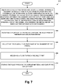
- Figure 7 is a block diagram of a method 200, according to an example embodiment.
- Method 200 shown in Figure 7 presents an embodiment of a method that could be used with the collection device 100 of Figures 1-6 , for example.
- Method 200 may include one or more operations, functions, or actions as illustrated by one or more of blocks 202-210. Although the blocks are illustrated in a sequential order, these blocks may in some instances be performed in parallel, and/or in a different order than those described herein. Also, the various blocks may be combined into fewer blocks, divided into additional blocks, and/or removed based upon the desired implementation.
- each block may represent a module, a segment, a portion of a manufacturing or operation process, or a portion of program code, which includes one or more instructions executable by a processor for implementing specific logical functions or steps in the process.
- the program code may be stored on any type of computer readable medium, for example, such as a storage device including a disk or hard drive.
- the computer readable medium may include non-transitory computer readable medium, for example, such as computer-readable media that stores data for short periods of time like register memory, processor cache and Random Access Memory (RAM).
- the computer readable medium may also include non-transitory media, such as secondary or persistent long term storage, like read only memory (ROM), optical or magnetic disks, compact-disc read only memory (CD-ROM), for example.
- the computer readable media may also be any other volatile or nonvolatile storage systems.
- the computer readable medium may be considered a computer readable storage medium, for example, or a tangible storage device.
- each block in Figure 2 may represent circuitry that is wired to perform the specific logical functions in the process.
- the method 200 includes providing a collection device including (i) a vessel defining a chamber, (ii) an inlet port in fluid communication with the chamber, (iii) an outlet port in fluid communication with the chamber, wherein the outlet port includes a porous material positioned between the chamber and the outlet port, and (iv) a sampling tube having a distal end and a proximal end, wherein the proximal end of the sampling tube extends from the proximal end of the vessel, and wherein the distal end of the sampling tube extends into the chamber.
- the method 200 includes receiving a plurality of particles through the inlet port of the particle collection device.
- the method 200 includes collecting the plurality of particles in the chamber of the vessel.
- the method 200 includes receiving a gas through the inlet port.
- the method 200 includes venting the gas through the porous material and out of the outlet port. Venting the gas through the porous material and out of the outlet port enables the separation of the produced particles from the gases, such as gaseous CO2.
- the method 200 further includes the steps of removing the plurality of particles from the chamber of the vessel. In yet another embodiment, the method further includes the steps of sampling one or more particles from the sampling tube, and adjusting one or more parameters of the particle formation system in response to the sampled one or more particles.
- Raw paclitaxel and docetaxel were purchased from Phyton Biotech (British Columbia, Canada), lot number FP2-15004 and DT7-14025, respectively. Both were characterized in their raw form.
- the milling of both drugs was accomplished using a Deco-PBM-V-0.41 mill (Deco). The milling conditions for both compounds were as follows:
- a solution of 65 mg/ml of paclitaxel was prepared in acetone.
- a BETE Micro Whirl ® fog nozzle (BETE Fog Nozzle, Inc) and a sonic probe (Qsonica, model number Q700) were positioned in the crystallization chamber approximately 8 mm apart.
- a stainless steel mesh filter with approximately 100 nm holes was attached to the crystallization chamber to collect the precipitated paclitaxel nanoparticles.
- the supercritical carbon dioxide was placed in the crystallization chamber of the manufacturing equipment and brought to approximately 1200 psi (82.737 Bar, 8.273 MPa) at about 38 °C and a flow rate of 24 kg/hour.
- the sonic probe was adjusted to 60% of total output power at a frequency of 20 kHz.
- Paclitaxel nanoparticles produced had an average number-weighted mean size of 0.81 ⁇ m with an average standard deviation of 0.74 ⁇ m over three separate runs.
- a solution of 79.32 mg/ml of docetaxel was prepared in ethanol.
- the nozzle and a sonic probe were positioned in the pressurizable chamber approximately 9 mm (apart.
- a stainless steel mesh filter with approximately 100 nm holes was attached to the pressurizable chamber to collect the precipitated docetaxel nanoparticles.
- the supercritical carbon dioxide was placed in the pressurizable chamber of the manufacturing equipment and brought to approximately 1200 psi (82.737 Bar, 8.273 MPa) at about 38 °C and a flow rate of 68 slpm.
- the sonic probe was adjusted to 60% of total output power at a frequency of 20 kHz.
- the ethanol solution containing the docetaxel was pumped through the nozzle at a flow rate of 2 mL/minute for approximately 95 minutes).
- the precipitated docetaxel agglomerates and particles were then collected from the supercritical carbon dioxide as the mixture is pumped through the stainless steel mesh filter.
- the filter containing the nanoparticles of docetaxel was opened and the resulting product was collected from the filter.
- Docetaxel nanoparticles produced had an average number-weighted mean size of 0.82 ⁇ m with an average standard deviation of 0.66 ⁇ m over three separate ethanol runs.
- Particle size was analyzed by both light obscuration and laser diffraction methods.
- An Particle Sizing Systems AccuSizer 780 SIS system was used for the light obscuration method and Shimadzu SALD-7101 was used for the laser diffraction method.
- Paclitaxel nanoparticles were analyzed using 0.10% (w/v) sodium dodecyl sulfate (SDS) in water as the dispersant.
- Docetaxel nanoparticles were analyzed using isopar G as the dispersant.
- Paclitaxel suspensions were prepared by adding approximately 7 mL of filtered dispersant to a glass vial containing approximately 4 mg of paclitaxel particles. The vials were vortexed for approximately 10 seconds and then sonicated in a sonic bath approximately 1 minute. If the sample was already suspended, 1:1 solution of paclitaxel suspension to 0.1% SDS solution was made, vortexed for 10 seconds, and sonicated in the sonic bath for 1 minute.
- Docetaxel suspensions were prepared by adding approximately 7 mL of filtered dispersant to a plastic vial containing approximately 4 mg of docetaxel particles. The vial was vortexed for approximately 10 seconds and then sonicated in a sonic bath for approximately 2 minutes. This suspension was used for laser diffraction analysis. Unused suspension was poured into a 125mL particle-free plastic bottle, which was then filled to approximately 100 mL with filtered dispersant. The suspension was vortex for approximately 10 seconds and then sonicated in the sonic bath for approximately 2 minutes. This diluted suspension was used for light obscuration analysis.
- a background test was first performed prior to analyzing particles on the AccuSizer 780 SIS,.
- a new particle-free plastic bottle was filled with blank suspension solution by pumping from a reservoir, using a peristaltic pump, through a 0.22 ⁇ m Millipore filter and into the bottle.
- a background analysis was run to ensure the particle/mL count was below 100 particles/mL.
- a known mass between 200 and 300 mg of the analyte was added to a 30 mL sample tube.
- the loaded tube was then mounted to a Porous Materials Inc. SORPTOMETER ® , model BET-202A.
- SORPTOMETER ® a Porous Materials Inc.
- the automated test was then carried out using the BETWIN ® software package and the surface area of each sample was subsequently calculated.
- Paclitaxel or docetaxel particle preparations were added to a 10 mL tared graduated cylinder through a plastic weigh funnel at room temperature. The mass of the drug was measured to a nearest 0.1 mg, the volume was determined to the nearest 0.1 mL and the density calculated.
- Approximately 50 mg of material i.e.: raw paclitaxel, milled paclitaxel, or paclitaxel particles
- Approximately 50 mg of material were coated on approximately 1.5 grams of 1 mm glass beads by tumbling the material and beads in a vial for approximately 1 hour. Beads were transferred to a stainless steel mesh container and placed in the dissolution bath containing methanol/water 50/50 (v/v) media at 37°C, pH 7, and a USP Apparatus II (Paddle), operating at 75 rpm.
- methanol/water 50/50 (v/v) media at 37°C, pH 7, and a USP Apparatus II (Paddle), operating at 75 rpm.
- a 5 mL aliquot was removed, filtered through a 0.22 ⁇ m filter and analyzed on a U(V/V)is spectrophotometer at 227 nm. Absorbance values of the samples were compared to those of standard solutions prepared in dissolution media to
- the BET surface area of particles produced using the above protocol and variations thereof ranged between 22 and 39 m 2 /g.
- Figure 1 shows exemplary particles produced using the methods of the invention.
- the BET surface area of raw paclitaxel was measured at 7.25 m 2 /g( Figure 2 ), while paclitaxel particles made according to the methods of US patents 5833891 and 5874029 ranged from 11.3 to 15.58 m 2 /g.
- Exemplary particle sizes produced using the methods of the invention are shown in Table 1.
Description
- A need exists for apparatuses and methods capable of producing sub-micron and nano-sized particles. The need is particularly pronounced in the field of pharmaceutics. Conventional techniques for particle-size reduction currently practiced suffer from many disadvantages. As such, a need remains for improved equipment and processes for the preparation, harvesting and collection of small particles.
-
US patent 8,778,181 B1 discloses an equipment assembly for and a method of processing pharmaceutic particles.Patent application WO 2005/054130 A1 relates to a device and process for the deposition of e.g. ultrafine silicon comprising particles from the gas phase by thermal decomposition. Patent applicationWO 95/01221 EP 2 258 748 A1 relates to resin particles (toner) and a method for producing the same.US patent application 2004/0031754 A1 (U.S. government and U.S. Army has certain rights) relates to a process for mixing energetic particulates resulting in energetic mixtures having e.g. a thermodynamic energy density from about 10 KJ/cc to about 20 KJ/cc. - The invention comprises a particle production system according to claim 1.
- These as well as other aspects and advantages will become apparent to those of ordinary skill in the art by reading the following detailed description, with reference where appropriate to the accompanying drawings.
-
-
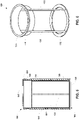
FIGURE 1 illustrates a perspective view of a particle collection device, according to an example embodiment. -
FIGURE 2 illustrates a top view of the particle collection device, according to an example embodiment. -
FIGURE 3 illustrates a cross-section view of the particle collection device, according to an example embodiment. -
FIGURE 4 illustrates another cross-section view of the particle collection device, according to an example embodiment. -
FIGURE 5 illustrates another cross-section view of the particle collection device, according to an example embodiment. -
FIGURE 6 illustrates a perspective view of a support frame, according to an example embodiment. -
FIGURE 7 is a block diagram of a method, according to an example embodiment. - As used herein, the singular forms "a", "an" and "the" include plural referents unless the context clearly dictates otherwise. "And" as used herein is interchangeably used with "or" unless expressly stated otherwise. All embodiments of any aspect of the invention can be used in combination, unless the context clearly dictates otherwise.
- As used herein, "about" means +/- 5% of the recited value.
- In one aspect, the present invention comprises a collection device, including (a) a vessel defining a chamber, wherein the vessel includes a distal end and a proximal end, (b) an inlet port extending from the proximal end of the vessel, wherein the inlet port is in fluid communication with the chamber, and (c) an outlet port extending from the proximal end of the vessel, wherein the outlet port is in fluid communication with the chamber, and wherein the outlet port includes a porous material positioned between the chamber and the outlet port.
- With reference to the Figures, as shown in
Figure 1 , the invention comprises acollection device 100 including avessel 102 defining achamber 104. Thevessel 102 includes adistal end 106 and aproximal end 108. The outer diameter of thevessel 102 may range from about 152.4 mm to about 914.4 mm. Thecollection device 100 further includes aninlet port 110 extending from theproximal end 108 of thevessel 102. Theinlet port 110 is in fluid communication with thechamber 104. Theinlet port 110 may have an outer diameter ranging from about 12.7 mm to about 101.6 mm. Further, thecollection device 100 includes anoutlet port 112 extending from theproximal end 108 of thevessel 102. As shown inFigures 3 and 4 , theoutlet port 112 is in fluid communication with thechamber 104, and theoutlet port 112 includes aporous material 114 positioned between thechamber 104 and theoutlet port 112. The outer diameter of the outlet port may range from about 12.7 mm to about 50.8 mm. - As shown in
Figures 1-4 , thecollection device 100 may further include asampling tube 116 having adistal end 118 and aproximal end 120. The outer diameter of thesampling tube 116 may range from about 6.35 mm to about 25.4 mm. As shown inFigures 3 and 4 , theproximal end 120 of thesampling tube 116 extends from theproximal end 108 of thevessel 102, and thedistal end 118 of thesampling tube 116 extends into thechamber 104. Thesampling tube 116 may be configured to remove a small sample of particles from thechamber 104 during a particle production run in which additional particles are being formed. In particular, thesampling tube 116 may include a sample thief that enables an operator to remove a small sample of particles without opening thechamber 104 or removing thesampling tube 116 from the rest of thecollection device 100 during processing. This enables an operator to test a small sample of particles to ensure that the product is within specifications as the process continues to run. For example, particle size or residual solvent analysis may be performed on the sample. If the measured specifications do not match the desired specifications, the operating parameters of the particle formation process may be suitably adjusted to correct the situation before an entire batch of product with undesirable characteristics is created. - The
porous material 114 positioned between thechamber 104 and theoutlet port 112 may take a variety of forms. In one example, theporous material 114 is selected from the group consisting of a frit, a mesh, a cloth. As one specific example, theporous material 114 may comprise a high-efficiency particulate arrestance (HEPA) filter. An example HEPA filter may include a mat of randomly arranged fibers, the fibers composed of fiberglass and possessing diameters between about 0.5 micrometers and about 2.0 micrometers. In another example, theporous material 114 comprises a sintered filter having adistal end 122 and aproximal end 124. In such an example, theproximal end 124 of the sintered filter extends from theproximal end 108 of thevessel 102 and is coupled to theoutlet port 112, and thedistal end 122 of the sintered filter extends into thechamber 104. Such a sintered filter may include a porous stainless steel filter cartridge, as an example. Other porous materials are possible as well. - The
inlet port 110 may include a coupling mechanism connecting an outlet of a particle filtration system to theinlet port 110. In one example, the coupling mechanism comprises one or more sanitary fittings. In another example, the coupling mechanism comprises a threaded connection between the outlet of the particle filtration system to theinlet port 110. In yet another example, the coupling mechanism comprises one or more compression fittings. Other example coupling mechanisms are possible as well. - Further, as shown in
Figure 5 , thecollection device 100 may further include acollection insert 126 positioned within thechamber 104 of thevessel 102, and asupport frame 128 positioned between aninterior wall 130 of thechamber 104 and the collection insert 126. The collection insert 126 may be a plastic bag, as an example. As shown inFigure 6 , thesupport frame 128 may include adistal ring 132, aproximal ring 134, one ormore support legs 136 connecting thedistal ring 132 to theproximal ring 134, and agasket 138 positioned adjacent to theproximal ring 134. In one example, thegasket 138 may comprise a neoprene gasket. Thevessel 102 may include aremovable lid 140 that can be removed to access thecollection insert 126 once particle collection is completed. In such an example, thecollection insert 126 may be positioned within thechamber 104 of thevessel 102 such that top edge of the collection insert 126 folds over the top of thesupport frame 128 and is sealed between thegasket 138 and theremovable lid 140 when the lid is in the closed position. Other arrangements are possible as well. - Further still, the components of the
collection device 100 may be a part of a larger particle production system. Such a particle production system may include one or more nozzle assemblies, a sonic energy source positioned adjacent to the orifice of each nozzle, one or more particle filtration systems in communication with one or more nozzle assemblies, and one or more particle collection devices, such as those described above, each in communication with the one or more particle filtration systems. In one example, the one or more particle filtration systems comprise a tandem particle filtration system including at least one high pressure harvesting filter system and at least one low pressure collection filter system in tandem and downstream to the harvesting filter. In such an example, the particle production system may include at least two particle harvesting filters, two particle collection filters and two collection devices. - In one example, the nozzle assembly includes (a) a vessel defining a pressurizable chamber, wherein the vessel includes a distal end and a proximal end, (b) an inlet of the pressurizable chamber at the proximal end of the vessel, (c) a nozzle positioned within the pressurizable chamber, wherein the nozzle includes an inlet tube in fluid communication with the inlet of the pressurizable chamber, wherein the nozzle includes an outlet aperture, wherein the nozzle is adjustable to alter a distance between the proximal end of the vessel and the outlet aperture of the nozzle, and wherein the nozzle is adjustable to alter an angle between a longitudinal axis of the vessel and a longitudinal axis of the nozzle, and (d) an outlet of the pressurizable chamber at the distal end of the vessel. In such an example, the
inlet port 110 of thecollection device 100 may be coupled to the outlet of the pressurizable chamber of the nozzle assembly. - In various embodiments, the one or more particle formation systems comprise one or more high pressure supercritical fluid (SCF) particle formation systems. In such an example, the one or more high pressure SCF particle formation systems may include a pressurizable precipitation chamber including a SCF inlet, a process fluid inlet, and a fluid outlet, and a process fluid disperser to disperse process fluid into the precipitation chamber. Any suitable pressurizable chamber may be used, including but not limited to those disclosed in
U.S. Patent Nos. 5,833,891 and5,874,029 . - In another example, the particle production system comprises at least one of a) two particle harvesting filters, two particle collection filters and two collection devices; b) two particle harvesting filters, one particle collection filter and one or more collection devices; c) two particle harvesting filters, two particle collection filters and one or more collection devices; d) two particle harvesting filters, one particle collection filter and one or more collection devices; e) two tandem filter particle harvesting and collection devices arranged in parallel; f) two or more particle harvesting filters arranged in parallel, one particle collection filter and two or more collection devices arranged in parallel; g) two or more precipitation chambers; h) at least two tandem filter particle filtration systems; i) at least two collection devices; or j) a combination thereof.
- In another aspect, which is not part of the invention methods for isolating particles are described comprising (a) providing a collection device including (i) a vessel defining a chamber, (ii) an inlet port in fluid communication with the chamber, (iii) an outlet port in fluid communication with the chamber, wherein the outlet port includes a porous material positioned between the chamber and the outlet port, and (iv) a sampling tube having a distal end and a proximal end, wherein the proximal end of the sampling tube extends from the proximal end of the vessel, and wherein the distal end of the sampling tube extends into the chamber, (b) receiving a plurality of particles through the inlet port of the particle collection device, (c) collecting the plurality of particles in the chamber of the vessel, (d) receiving a gas through the inlet port, and (e) venting the gas through the porous material and out of the outlet port.
-
Figure 7 is a block diagram of amethod 200, according to an example embodiment.Method 200 shown inFigure 7 presents an embodiment of a method that could be used with thecollection device 100 ofFigures 1-6 , for example.Method 200 may include one or more operations, functions, or actions as illustrated by one or more of blocks 202-210. Although the blocks are illustrated in a sequential order, these blocks may in some instances be performed in parallel, and/or in a different order than those described herein. Also, the various blocks may be combined into fewer blocks, divided into additional blocks, and/or removed based upon the desired implementation. - In addition, for the
method 200 and other processes and methods disclosed herein, the flowchart shows functionality and operation of one possible implementation of present embodiments. In this regard, each block may represent a module, a segment, a portion of a manufacturing or operation process, or a portion of program code, which includes one or more instructions executable by a processor for implementing specific logical functions or steps in the process. The program code may be stored on any type of computer readable medium, for example, such as a storage device including a disk or hard drive. The computer readable medium may include non-transitory computer readable medium, for example, such as computer-readable media that stores data for short periods of time like register memory, processor cache and Random Access Memory (RAM). The computer readable medium may also include non-transitory media, such as secondary or persistent long term storage, like read only memory (ROM), optical or magnetic disks, compact-disc read only memory (CD-ROM), for example. The computer readable media may also be any other volatile or nonvolatile storage systems. The computer readable medium may be considered a computer readable storage medium, for example, or a tangible storage device. - In addition, for the
method 200 and other processes and methods disclosed herein, each block inFigure 2 may represent circuitry that is wired to perform the specific logical functions in the process. - At
block 202, themethod 200 includes providing a collection device including (i) a vessel defining a chamber, (ii) an inlet port in fluid communication with the chamber, (iii) an outlet port in fluid communication with the chamber, wherein the outlet port includes a porous material positioned between the chamber and the outlet port, and (iv) a sampling tube having a distal end and a proximal end, wherein the proximal end of the sampling tube extends from the proximal end of the vessel, and wherein the distal end of the sampling tube extends into the chamber. - At
block 204, themethod 200 includes receiving a plurality of particles through the inlet port of the particle collection device. Atblock 206, themethod 200 includes collecting the plurality of particles in the chamber of the vessel. Atblock 208, themethod 200 includes receiving a gas through the inlet port. Atblock 210, themethod 200 includes venting the gas through the porous material and out of the outlet port. Venting the gas through the porous material and out of the outlet port enables the separation of the produced particles from the gases, such as gaseous CO2. - In one embodiment, the
method 200 further includes the steps of removing the plurality of particles from the chamber of the vessel. In yet another embodiment, the method further includes the steps of sampling one or more particles from the sampling tube, and adjusting one or more parameters of the particle formation system in response to the sampled one or more particles. - Raw paclitaxel and docetaxel were purchased from Phyton Biotech (British Columbia, Canada), lot number FP2-15004 and DT7-14025, respectively. Both were characterized in their raw form. The milling of both drugs was accomplished using a Deco-PBM-V-0.41 mill (Deco). The milling conditions for both compounds were as follows:
- Ball size = 5 mm
- RPM = 600
- Processing time = 60 min
- Room temperature.
- A solution of 65 mg/ml of paclitaxel was prepared in acetone. A BETE Micro Whirl® fog nozzle (BETE Fog Nozzle, Inc) and a sonic probe (Qsonica, model number Q700) were positioned in the crystallization chamber approximately 8 mm apart. A stainless steel mesh filter with approximately 100 nm holes was attached to the crystallization chamber to collect the precipitated paclitaxel nanoparticles. The supercritical carbon dioxide was placed in the crystallization chamber of the manufacturing equipment and brought to approximately 1200 psi (82.737 Bar, 8.273 MPa) at about 38 °C and a flow rate of 24 kg/hour. The sonic probe was adjusted to 60% of total output power at a frequency of 20 kHz. The acetone solution containing the paclitaxel was pumped through the nozzle at a flow rate of 4.5 mL/minute for approximately 36 hours. Paclitaxel nanoparticles produced had an average number-weighted mean size of 0.81 µm with an average standard deviation of 0.74 µm over three separate runs.
- A solution of 79.32 mg/ml of docetaxel was prepared in ethanol. The nozzle and a sonic probe were positioned in the pressurizable chamber approximately 9 mm (apart. A stainless steel mesh filter with approximately 100 nm holes was attached to the pressurizable chamber to collect the precipitated docetaxel nanoparticles. The supercritical carbon dioxide was placed in the pressurizable chamber of the manufacturing equipment and brought to approximately 1200 psi (82.737 Bar, 8.273 MPa) at about 38 °C and a flow rate of 68 slpm. The sonic probe was adjusted to 60% of total output power at a frequency of 20 kHz. The ethanol solution containing the docetaxel was pumped through the nozzle at a flow rate of 2 mL/minute for approximately 95 minutes). The precipitated docetaxel agglomerates and particles were then collected from the supercritical carbon dioxide as the mixture is pumped through the stainless steel mesh filter. The filter containing the nanoparticles of docetaxel was opened and the resulting product was collected from the filter.
- Docetaxel nanoparticles produced had an average number-weighted mean size of 0.82 µm with an average standard deviation of 0.66 µm over three separate ethanol runs.
- Particle size was analyzed by both light obscuration and laser diffraction methods. An Particle Sizing Systems AccuSizer 780 SIS system was used for the light obscuration method and Shimadzu SALD-7101 was used for the laser diffraction method. Paclitaxel nanoparticles were analyzed using 0.10% (w/v) sodium dodecyl sulfate (SDS) in water as the dispersant. Docetaxel nanoparticles were analyzed using isopar G as the dispersant.
- Paclitaxel suspensions were prepared by adding approximately 7 mL of filtered dispersant to a glass vial containing approximately 4 mg of paclitaxel particles. The vials were vortexed for approximately 10 seconds and then sonicated in a sonic bath approximately 1 minute. If the sample was already suspended, 1:1 solution of paclitaxel suspension to 0.1% SDS solution was made, vortexed for 10 seconds, and sonicated in the sonic bath for 1 minute.
- Docetaxel suspensions were prepared by adding approximately 7 mL of filtered dispersant to a plastic vial containing approximately 4 mg of docetaxel particles. The vial was vortexed for approximately 10 seconds and then sonicated in a sonic bath for approximately 2 minutes. This suspension was used for laser diffraction analysis. Unused suspension was poured into a 125mL particle-free plastic bottle, which was then filled to approximately 100 mL with filtered dispersant. The suspension was vortex for approximately 10 seconds and then sonicated in the sonic bath for approximately 2 minutes. This diluted suspension was used for light obscuration analysis.
- A background test was first performed prior to analyzing particles on the AccuSizer 780 SIS,. A new particle-free plastic bottle was filled with blank suspension solution by pumping from a reservoir, using a peristaltic pump, through a 0.22 µm Millipore filter and into the bottle. A background analysis was run to ensure the particle/mL count was below 100 particles/mL. A small amount of paclitaxel suspension, 5-100 µL, depending upon concentration of solution, was pipetted into the plastic bottle in place from the background test and was filled with ~100 mL dispersant and the analysis was started. Counts were monitored and paclitaxel solution added to reach and/or maintain 6000-8000 particle counts/mL during the entire analysis. Once the analysis was completed, the background data was removed and any measurement with less than four counts was removed.
- To analyze particles on SALD-7101 using a batch cell, the analysis was started by choosing Manual Measurement. The refractive index was set as 1.5 to 1.7. The batch cell was filled with filtered dispersant just past the etched line. The blank measurement was ran. A small amount of API (paclitaxel or docetaxel) suspension was pipetted, generally < 1 mL, depending upon concentration of solution as low as 100 µL, into the batch cell as needed to achieve an acceptable absorbance between 0.15 and 0.2 absorbance units. The measurements were executed, and the resulting graph with the highest level of confidence was selected; background was automatically accounted for.
- A known mass between 200 and 300 mg of the analyte was added to a 30 mL sample tube. The loaded tube was then mounted to a Porous Materials Inc. SORPTOMETER®, model BET-202A. The automated test was then carried out using the BETWIN® software package and the surface area of each sample was subsequently calculated.
- Paclitaxel or docetaxel particle preparations were added to a 10 mL tared graduated cylinder through a plastic weigh funnel at room temperature. The mass of the drug was measured to a nearest 0.1 mg, the volume was determined to the nearest 0.1 mL and the density calculated.
- Approximately 50 mg of material (i.e.: raw paclitaxel, milled paclitaxel, or paclitaxel particles) were coated on approximately 1.5 grams of 1 mm glass beads by tumbling the material and beads in a vial for approximately 1 hour. Beads were transferred to a stainless steel mesh container and placed in the dissolution bath containing methanol/water 50/50 (v/v) media at 37°C, pH 7, and a USP Apparatus II (Paddle), operating at 75 rpm. At 10, 20, 30, 60, and 90 minutes, a 5 mL aliquot was removed, filtered through a 0.22 µm filter and analyzed on a U(V/V)is spectrophotometer at 227 nm. Absorbance values of the samples were compared to those of standard solutions prepared in dissolution media to determine the amount of material dissolved.
- Approximately 50 mg of material (i.e.: raw docetaxel, milled docetaxel, or docetaxel particles) was placed directly in the dissolution bath containing methanol/water 15/85 (v/v) media at 37°C, pH 7, and a USP Apparatus II (Paddle), operating at 75 rpm. At 5, 15, 30, 60, 120 and 225 minutes, a 5 mL aliquot was removed, filtered through a 0.22 µm filter, and analyzed on a UV/VIS spectrophotometer at 232 nm. Absorbance values of the samples were compared to those of standard solutions prepared in dissolution media to determine the amount of material dissolved.
- The BET surface area of particles produced using the above protocol and variations thereof (i.e.: modifying nozzles, filters, sonic energy sources, flow rates, etc.) ranged between 22 and 39 m2/g.
Figure 1 shows exemplary particles produced using the methods of the invention. By comparison, the BET surface area of raw paclitaxel was measured at 7.25 m2/g(Figure 2 ), while paclitaxel particles made according to the methods ofUS patents 5833891 and5874029 ranged from 11.3 to 15.58 m2/g. Exemplary particle sizes produced using the methods of the invention are shown in Table 1.
- Comparative studies on bulk density, SSA, and dissolution rates (carried out as noted above) for raw drug, milled drug particles, and drug particles produced by the methods of the present invention are provided in Tables 2 and 3 below. The full dissolution time course for the paclitaxel and docetaxel materials are provided in Tables 4 and 5, respectively.
Table 2 Compound: Paclitaxel Particles Milled Characteristic Raw Material Batch 1 Batch 2 Mean Number Mean (um) 1.16 0.83 0.67 0.75 0.89 Volume Mean (um) 1.29 1.42 0.57 1.00 1.35 Bulk Density (g/cm3) 0.26 0.060 0.11 0.085 0.31 Surface Area (m2/g) 10.4 35.6 39.8 37.7 15.0 Dissolution (30 min) 18% 42% 52% 47% 32% Table 3 Compound: Docetaxel Particles Characteristic Raw Material Batch 1 Batch II Mean Milled Number Mean (um) 1.58 0.92 0.80 0.86 1.11 Volume Mean (um) 5.05 4.88 4.03 4.46 3.73 Bulk Density (g/cm3) 0.24 0.062 0.096 0.079 0.44 Surface Area (m2/g) 15.9 43.0 45.4 44.2 15.2 Dissolution (30min) 11% 27% 27% 27% 9% Table 4: Paclitaxel Dissolution time course Timepoint (minutes) Paclitaxel Raw Material Paclitaxel Particles Milled Paclitaxel 0 0.0% 0.0% 0.0% 10 14.0% 40.2% 23.0% 20 17.8% 47.6% 30.0% 30 18.4% 51.9% 32.3% 60 23.9% 58.3% 38.6% 90 28.6% 62.9% 43.5% Table 5: Docetaxel Dissolution time course Timepoint (minutes) Docetaxel Raw Material Docetaxel Particles Milled Docetaxel 0 0.0% 0.0% 0.0% 5 3.2% 12.1% 3.2% 15 6.9% 21.7% 5.9% 30 11.2% 27.2% 9.3% 60 16.4% 32.9% 12.2% 120 22.4% 38.9% 13.6% 225 26.8% 43.1% 16.0%
Claims (8)
- A particle production system, comprising:one or more high pressure supercritical fluid (SCF) particle formation systems capable of producing a plurality of sub-micron particles;one or more particle filtration systems in communication with the one or more particle formation systems;and one or more particle collection devices (100) in communication with the one or more particle filtration systems and the one or more particle collection devices (100) being part of the particle production system and the one or more particle collection devices (100) are configured to collect the particles,the one or more particle collection devices (100), comprising:a vessel (102) defining a chamber (104) for collecting the plurality of particles, wherein the vessel (102) includes a distal end (106) and a proximal end (108);an inlet port (110) extending from the proximal end (108) of the vessel (102) and configured to receive the plurality of particles and a gas, wherein the inlet port (110) is in fluid communication with the chamber (104),wherein the inlet port (110) includes a coupling mechanism, connecting an outlet of the one or more particle filtration systems to the inlet port (110); andan outlet port (112) extending from the proximal end (108) of the vessel (102), wherein the outlet port (112) is in fluid communication with the chamber (104), and wherein the outlet port (112) includes a porous material (114) positioned between the chamber (104) and the outlet port (112),wherein the outlet port (112) is configured to vent the gas through the porous material (114) and out of the outlet port (112) enabling the separation of the produced particles from the gases,characterized by:a collection insert (126) positioned within the chamber (104);wherein the collection insert (126) comprises a plastic bag;a support frame (128) positioned between an interior wall of the chamber (104) and the collection insert (126) to thereby support the collection insert (126) within the chamber (104),wherein the support frame (128) comprises a distal ring (132), a proximal ring (134), one or more support legs (136) connecting the distal ring (132) to the proximal ring (134), and a gasket (138) positioned adjacent to the proximal ring (134),wherein the outer diameter of the support frame (128) corresponds to the inner diameter of the vessel (102),wherein a distal end of the collection insert (126) extends up to the distal ring (132), a removable lid (140) positioned at the proximal end (108) of the vessel (102), the collection insert (126) is configured to be positioned within the chamber (104) of the vessel (102) such that the top edge of the collection insert (126) folds over the top of the support frame (128) and is sealed between the gasket (138) and the removable lid (149) when the removable lid is in a closed position,wherein the inlet port (110) and the outlet port (112) are arranged on the removable lid (140),wherein the particle collection device (100) further comprises:
a sampling tube (116) having a distal end and a proximal end, wherein the proximal end of the sampling tube (116) extends from the proximal end (108) of the vessel (102), and wherein the distal end of the sampling tube (116) extends into the chamber (104). - The system of claim 1, wherein the gasket (138) comprises a neoprene gasket.
- The system of any one of claims 1-2, wherein the porous material (114) is selected from the group consisting of a frit, a mesh, and a cloth.
- The system of any one of claims 1-3, wherein the porous material (114) comprises a sintered filter having a distal end (122) and a proximal end (124), wherein the proximal end (124) of the sintered filter extends from the proximal end (108) of the vessel (102) and is coupled to the outlet port (112), and wherein the distal end (122) of the sintered filter extends into the chamber (104).
- The system of any one of claims 1-4, whereinan outer diameter of the inlet port (110) has a range from about 12.7 mm to about 101.6 mm, and/oran outer diameter of the outlet port (112) has a range from about 12.7 mm to about 50.8 mm, and/oran outer diameter of the sampling tube (116) has a range from about 6.35 mm to about 25.4 mm, and/oran outer diameter of the vessel (102) has a range from about 152.4 mm to about 914.4 mm.
- The system of any one of claims 1 to 5, wherein the coupling mechanism comprises one or more sanitary fittings.
- The system of any one of claims 1 to 5, wherein the coupling mechanism comprises one or more compression fittings.
- The system of claim 1, wherein the one or more particle formation systems comprise one or more high pressure supercritical fluid (SCF) particle formation systems, and wherein the one or more high pressure SCF particle formation systems include:a pressurizable precipitation chamber including a SCF inlet, a process fluid inlet, and a fluid outlet; anda process fluid disperser to disperse process fluid into the precipitation chamber.
Applications Claiming Priority (4)
| Application Number | Priority Date | Filing Date | Title |
|---|---|---|---|
| US201562171008P | 2015-06-04 | 2015-06-04 | |
| US201562171001P | 2015-06-04 | 2015-06-04 | |
| US201562171060P | 2015-06-04 | 2015-06-04 | |
| PCT/US2016/036013 WO2016197101A1 (en) | 2015-06-04 | 2016-06-06 | Collection device and methods for use |
Publications (2)
| Publication Number | Publication Date |
|---|---|
| EP3302423A1 EP3302423A1 (en) | 2018-04-11 |
| EP3302423B1 true EP3302423B1 (en) | 2022-05-25 |
Family
ID=56194575
Family Applications (4)
| Application Number | Title | Priority Date | Filing Date |
|---|---|---|---|
| EP16732387.2A Active EP3302431B1 (en) | 2015-06-04 | 2016-06-06 | Taxane particles and their use |
| EP16731712.2A Active EP3302780B1 (en) | 2015-06-04 | 2016-06-06 | Nozzle assembly, method and computer readable medium for use |
| EP16734493.6A Active EP3302423B1 (en) | 2015-06-04 | 2016-06-06 | Particle production system and particle collection device |
| EP20206804.5A Pending EP3838264A1 (en) | 2015-06-04 | 2016-06-06 | Taxane particles and their use |
Family Applications Before (2)
| Application Number | Title | Priority Date | Filing Date |
|---|---|---|---|
| EP16732387.2A Active EP3302431B1 (en) | 2015-06-04 | 2016-06-06 | Taxane particles and their use |
| EP16731712.2A Active EP3302780B1 (en) | 2015-06-04 | 2016-06-06 | Nozzle assembly, method and computer readable medium for use |
Family Applications After (1)
| Application Number | Title | Priority Date | Filing Date |
|---|---|---|---|
| EP20206804.5A Pending EP3838264A1 (en) | 2015-06-04 | 2016-06-06 | Taxane particles and their use |
Country Status (14)
| Country | Link |
|---|---|
| US (11) | US9814685B2 (en) |
| EP (4) | EP3302431B1 (en) |
| JP (5) | JP6892394B2 (en) |
| KR (5) | KR102551708B1 (en) |
| CN (4) | CN107743418A (en) |
| AU (3) | AU2016270559B2 (en) |
| CA (3) | CA3026454C (en) |
| DK (1) | DK3302431T3 (en) |
| ES (1) | ES2833749T3 (en) |
| HK (3) | HK1253018A1 (en) |
| PT (1) | PT3302431T (en) |
| RU (1) | RU2750163C2 (en) |
| SG (2) | SG10201913947RA (en) |
| WO (3) | WO2016197101A1 (en) |
Families Citing this family (29)
| Publication number | Priority date | Publication date | Assignee | Title |
|---|---|---|---|---|
| KR102551708B1 (en) | 2015-06-04 | 2023-07-06 | 크리티테크, 인크. | Collection device and method of use |
| WO2017049083A2 (en) | 2015-09-16 | 2017-03-23 | Dfb Soria, Llc | Delivery of drug nanoparticles and methods of use thereof |
| KR20230017354A (en) | 2016-04-04 | 2023-02-03 | 크리티테크, 인크. | Methods for Solid Tumor Treatment |
| CN108602258B (en) * | 2016-05-12 | 2022-02-22 | 惠普发展公司有限责任合伙企业 | Build material container |
| WO2018170207A1 (en) * | 2017-03-15 | 2018-09-20 | Dfb Soria, Llc | Topical therapy for the treatment of skin keratoses using nanoparticles of taxanes |
| CN110636833A (en) | 2017-03-15 | 2019-12-31 | Dfb索里亚有限责任公司 | Topical therapy using taxane nanoparticles for the treatment of skin malignancies |
| WO2018170210A1 (en) | 2017-03-15 | 2018-09-20 | Dfb Soria, Llc | Topical therapy for the treatment of vulvar intraepithelial neoplasia (vin) and genital warts using nanoparticles of taxanes |
| JP2020523285A (en) | 2017-06-09 | 2020-08-06 | クリチテック,インコーポレイテッド | Treatment of epithelial cysts by intracystic injection of antitumor particles |
| US10398646B2 (en) * | 2017-06-14 | 2019-09-03 | Crititech, Inc. | Methods for treating lung disorders |
| US20200170992A1 (en) * | 2017-07-07 | 2020-06-04 | Dfb Pharmaceuticals, Llc | Treatment of hyperplastic tissue growths including benign prostatic hyperplasia (bph) by direct injection of an antineoplastic agent |
| US11931368B2 (en) | 2017-09-29 | 2024-03-19 | Crititech, Inc. | Glucocorticoid “nintedanib” particles and their use |
| EP3687977A1 (en) | 2017-09-29 | 2020-08-05 | Crititech, Inc. | Ciprofloxacin polymorph and its use |
| CN111278436A (en) | 2017-10-03 | 2020-06-12 | 克里蒂泰克公司 | Local delivery of anti-tumor particles in combination with systemic delivery of immunotherapeutic agents for the treatment of cancer |
| WO2019136187A1 (en) | 2018-01-05 | 2019-07-11 | Crititech, Inc. | Treatment of bladder cancer by local administration of taxane particles |
| EP3765035A4 (en) * | 2018-03-16 | 2021-10-27 | DFB Soria, LLC | Topical therapy for the treatment of cervical intraepithelial neoplasia (cin) and cervical cancer using nanoparticles of taxanes |
| US20190365700A1 (en) | 2018-05-31 | 2019-12-05 | Crititech, Inc. | Methods for Isolating Tumor-Specific Immune Cells from a Subject for Adoptive Cell Therapy and Cancer Vaccines |
| WO2019231498A1 (en) | 2018-05-31 | 2019-12-05 | Crititech, Inc. | Treatment of kidney tumors by intratumoral injection of taxane particles |
| US20190365698A1 (en) | 2018-05-31 | 2019-12-05 | Crititech, Inc. | Use of Antineoplastic Agents to Stimulate the Immune System for Treatment of Cancer |
| CN108970835B (en) * | 2018-09-20 | 2020-11-17 | 马鞍山纽泽科技服务有限公司 | High-temperature-resistant injection device |
| WO2020072090A1 (en) | 2018-10-03 | 2020-04-09 | Crititech, Inc. | Use of antineoplastic agents to stimulate the immune system for production of tertiary lymphoid structures (tls) |
| US11911499B2 (en) | 2019-11-07 | 2024-02-27 | Resurge Therapeutics, Inc. | System and method for prostate treatment |
| AU2021215858A1 (en) * | 2020-02-04 | 2022-09-15 | Zhuhai Beihai Biotech Co., Ltd. | Formulations of docetaxel |
| KR20230044422A (en) * | 2020-07-23 | 2023-04-04 | 크리티테크, 인크. | Sorafenib Particles and Uses Thereof |
| BR112023000501A2 (en) | 2020-07-23 | 2023-01-31 | Crititech Inc | LAPATINIB PARTICLES AND USES THEREOF |
| CN113447635B (en) * | 2021-05-11 | 2023-09-29 | 江西农业大学 | Potted plant soil greenhouse gas release rate measuring device with different depths |
| WO2023086779A1 (en) | 2021-11-10 | 2023-05-19 | Crititech, Inc. | Niraparib particles and uses thereof |
| US11738029B2 (en) | 2021-11-10 | 2023-08-29 | Crititech, Inc. | Rucaparib particles and uses thereof |
| US11602516B1 (en) | 2022-01-29 | 2023-03-14 | Resurge Therapeutics Inc. | Treating benign prostatic hyperplasia |
| US11957654B2 (en) | 2022-01-29 | 2024-04-16 | Resurge Therapeutics, Inc. | Treating benign prostatic hyperplasia |
Citations (1)
| Publication number | Priority date | Publication date | Assignee | Title |
|---|---|---|---|---|
| US20040031754A1 (en) * | 2002-08-13 | 2004-02-19 | Pesiri David Richard | Process for mixing particulates |
Family Cites Families (153)
| Publication number | Priority date | Publication date | Assignee | Title |
|---|---|---|---|---|
| US3648698A (en) * | 1969-05-23 | 1972-03-14 | George O Doherty | Surgical collection unit |
| DE3120047C2 (en) * | 1981-05-20 | 1984-03-29 | Sterimed Gesellschaft für medizinischen Bedarf mbH, 6600 Saarbrücken | Suction device for sucking in body secretions |
| JPS5958019U (en) | 1982-10-08 | 1984-04-16 | 松下電器産業株式会社 | electric dust collector |
| US4780138A (en) * | 1986-10-27 | 1988-10-25 | Bodine Albert G | Sonic apparatus and method for facilitating the extraction of minerals from ore in a leachant |
| US5143528A (en) | 1990-02-14 | 1992-09-01 | Challenge Industries | Lint collector |
| US5399363A (en) | 1991-01-25 | 1995-03-21 | Eastman Kodak Company | Surface modified anticancer nanoparticles |
| US6749868B1 (en) | 1993-02-22 | 2004-06-15 | American Bioscience, Inc. | Protein stabilized pharmacologically active agents, methods for the preparation thereof and methods for the use thereof |
| GB9313642D0 (en) | 1993-07-01 | 1993-08-18 | Glaxo Group Ltd | Method and apparatus for the formation of particles |
| US5409833A (en) * | 1993-07-01 | 1995-04-25 | Baxter International Inc. | Microvessel cell isolation apparatus |
| US5716981A (en) | 1993-07-19 | 1998-02-10 | Angiogenesis Technologies, Inc. | Anti-angiogenic compositions and methods of use |
| GB9413202D0 (en) | 1994-06-30 | 1994-08-24 | Univ Bradford | Method and apparatus for the formation of particles |
| US5626862A (en) | 1994-08-02 | 1997-05-06 | Massachusetts Institute Of Technology | Controlled local delivery of chemotherapeutic agents for treating solid tumors |
| US5480540A (en) | 1994-10-17 | 1996-01-02 | General Electric Company | Spray apparatus for separating solids from fluids |
| US5874481A (en) | 1995-06-07 | 1999-02-23 | Alliance Pharmaceutical Corp. | Fluorochemical solutions for the delivery of lipophilic pharmaceutical agents |
| US5874029A (en) | 1996-10-09 | 1999-02-23 | The University Of Kansas | Methods for particle micronization and nanonization by recrystallization from organic solutions sprayed into a compressed antisolvent |
| US5833891A (en) | 1996-10-09 | 1998-11-10 | The University Of Kansas | Methods for a particle precipitation and coating using near-critical and supercritical antisolvents |
| US6495579B1 (en) | 1996-12-02 | 2002-12-17 | Angiotech Pharmaceuticals, Inc. | Method for treating multiple sclerosis |
| DE69737510T2 (en) | 1996-12-30 | 2007-12-06 | Battelle Memorial Institute, Columbus | Use of an unencapsulated anticancer drug for the preparation of a preparation for the treatment of neoplasms by inhalation |
| CA2294981C (en) | 1997-06-27 | 2012-04-03 | Vivorx Pharmaceuticals, Inc. | Novel formulations of pharmacological agents, methods for the preparation thereof and methods for the use thereof |
| US6117949A (en) | 1998-10-01 | 2000-09-12 | Macromed, Inc. | Biodegradable low molecular weight triblock poly (lactide-co-glycolide) polyethylene glycol copolymers having reverse thermal gelation properties |
| JPH11189403A (en) | 1997-12-25 | 1999-07-13 | Tic:Kk | Device for producing layer structure composite particle |
| JP3418751B2 (en) | 1998-01-22 | 2003-06-23 | 参天製薬株式会社 | Fluorometholone suspension ophthalmic solution |
| IL131217A0 (en) | 1998-03-10 | 2001-01-28 | Napro Biotherapeutics Inc | Novel methods and compositions for delivery of taxanes |
| US6221153B1 (en) | 1998-06-09 | 2001-04-24 | Trevor Percival Castor | Method for producing large crystals of complex molecules |
| US7521068B2 (en) | 1998-11-12 | 2009-04-21 | Elan Pharma International Ltd. | Dry powder aerosols of nanoparticulate drugs |
| US6113795A (en) | 1998-11-17 | 2000-09-05 | The University Of Kansas | Process and apparatus for size selective separation of micro- and nano-particles |
| AU1556800A (en) | 1998-11-25 | 2000-06-13 | Universitatsklinikum Freiburg | Hyperforin as cytostatic agent and hyperforin ointment or cream as application form |
| US6537585B1 (en) | 1999-03-26 | 2003-03-25 | Guilford Pharmaceuticals, Inc. | Methods and compositions for treating solid tumors |
| US7217735B1 (en) | 1999-04-09 | 2007-05-15 | Au Jessie L-S | Methods and compositions for enhancing delivery of therapeutic agents to tissues |
| NZ516083A (en) * | 1999-05-27 | 2003-08-29 | Acusphere Inc | Porous drug matrices and methods of manufacture thereof |
| US6610317B2 (en) | 1999-05-27 | 2003-08-26 | Acusphere, Inc. | Porous paclitaxel matrices and methods of manufacture thereof |
| US6858199B1 (en) | 2000-06-09 | 2005-02-22 | Advanced Inhalation Research, Inc. | High efficient delivery of a large therapeutic mass aerosol |
| US6616849B1 (en) | 1999-08-25 | 2003-09-09 | Shimadzu Corporation | Method of and system for continuously processing liquid materials, and the product processed thereby |
| JP2003513756A (en) | 1999-11-12 | 2003-04-15 | アンジオテック ファーマシューティカルズ,インコーポレイテッド | Compositions of a combination of radiotherapy and a cell cycle inhibitor |
| SE0001543L (en) * | 2000-04-28 | 2001-09-10 | Bst Ab | Method and apparatus for suction and transport of liquids, preferably blood |
| US6620351B2 (en) | 2000-05-24 | 2003-09-16 | Auburn University | Method of forming nanoparticles and microparticles of controllable size using supercritical fluids with enhanced mass transfer |
| US6562952B1 (en) | 2000-10-31 | 2003-05-13 | The University Of Kansas | Precipitation of proteins from organic solutions |
| US20020081339A1 (en) | 2000-12-22 | 2002-06-27 | Philippe Menei | Treatment of inoperable tumors by stereotactic injection of microspheres |
| JP2004529934A (en) | 2001-05-01 | 2004-09-30 | アンジオテック ファーマシューティカルズ,インコーポレイテッド | Compositions comprising anti-microtubule agents and polypeptides or polysaccharides, and uses of those compositions for the preparation of a medicament for treating inflammatory conditions |
| DK1401563T4 (en) | 2001-07-02 | 2016-01-11 | Cerbios Pharma Sa | A process for producing micro and / or nano-particles |
| US20030054042A1 (en) | 2001-09-14 | 2003-03-20 | Elaine Liversidge | Stabilization of chemical compounds using nanoparticulate formulations |
| US20030134810A1 (en) | 2001-10-09 | 2003-07-17 | Chris Springate | Methods and compositions comprising biocompatible materials useful for the administration of therapeutic agents |
| CN1592607A (en) * | 2001-10-15 | 2005-03-09 | 克里蒂泰克公司 | Compositions and methods for delivery of poorly water soluble drugs and methods of treatment |
| WO2003043586A2 (en) | 2001-11-20 | 2003-05-30 | Advanced Inhalation Research, Inc. | Compositions for sustained action product delivery |
| EP1480691A4 (en) | 2002-03-05 | 2007-11-28 | Univ State Cleveland | Agglomerated particles for aerosol drug delivery |
| JP2003251127A (en) | 2002-03-06 | 2003-09-09 | Kazuo Hirakawa | Dust collector |
| ATE343376T1 (en) | 2002-03-20 | 2006-11-15 | Elan Pharma Int Ltd | NANOPARTICLE COMPOSITIONS OF ANGIOGENESIS INHIBITORS |
| EP1501483A2 (en) * | 2002-04-25 | 2005-02-02 | Nektar Therapeutics UK Ltd | Particulate materials |
| KR20050026699A (en) | 2002-04-26 | 2005-03-15 | 테바 파마슈티컬 인더스트리즈 리미티드 | Microparticle pharmaceutical compositions for intratumoral delivery |
| US9339459B2 (en) * | 2003-04-24 | 2016-05-17 | Nektar Therapeutics | Particulate materials |
| CN1255394C (en) | 2002-06-24 | 2006-05-10 | 成都思摩纳米技术有限公司 | Process for the manufacture of pacilitaxel nano granule |
| KR100573289B1 (en) | 2002-07-20 | 2006-04-24 | 대화제약 주식회사 | Paclitaxel composition for the intravesical treatment of bladder tumor and preparation method thereof |
| CN2578811Y (en) * | 2002-10-24 | 2003-10-08 | 陆纪清 | Closed coal powder sampler |
| CA2504268A1 (en) * | 2002-10-30 | 2004-11-18 | Spherics, Inc. | Nanoparticulate bioactive agents |
| KR100508518B1 (en) * | 2002-11-13 | 2005-08-17 | 한미약품 주식회사 | Method for the preparation of paclitaxel solid dispersion by using the supercritical fluid process and paclitaxel solid dispersion prepared thereby |
| AU2003299590B8 (en) | 2002-12-09 | 2010-04-08 | Abraxis Bioscience, Llc | Compositions and methods of delivery of pharmacological agents |
| US7455797B2 (en) | 2003-02-28 | 2008-11-25 | Ferro Corporation | Method and apparatus for producing particles using supercritical fluid |
| WO2004089291A2 (en) | 2003-04-03 | 2004-10-21 | Au Jessie L-S | Tumor-targeting drug-loaded particles |
| US20060147535A1 (en) | 2003-04-16 | 2006-07-06 | Poongunran Muthukumaran | Methods for and compositions of anticancer medicaments |
| US20050059613A1 (en) | 2003-07-08 | 2005-03-17 | Bahram Memarzadeh | Compositions and methods for the enhanced uptake of therapeutic agents through the bladder epithelium |
| US8021831B2 (en) | 2003-08-25 | 2011-09-20 | Board Of Regents, The University Of Texas System | Taxane chemosensitivity prediction test |
| JP2007001865A (en) | 2003-09-16 | 2007-01-11 | Ltt Bio-Pharma Co Ltd | Fine particle enclosing fat-soluble medicine, method for producing the same and preparation containing the same |
| CA2542217C (en) | 2003-10-15 | 2018-03-27 | Medigene Ag | Method of administering cationic liposomes comprising an active drug |
| TWI371274B (en) * | 2003-10-23 | 2012-09-01 | Bristol Myers Squibb Co | Process for making sterile aripiprazole of desired mean particle size |
| US7208106B2 (en) | 2003-10-24 | 2007-04-24 | Ferro Corporation | Method of forming particles |
| US7879360B2 (en) | 2003-11-05 | 2011-02-01 | Elan Pharma International, Ltd. | Nanoparticulate compositions having a peptide as a surface stabilizer |
| DE10357091A1 (en) | 2003-12-06 | 2005-07-07 | Degussa Ag | Device and method for the separation of very fine particles from the gas phase |
| GB0402963D0 (en) | 2004-02-11 | 2004-03-17 | Univ Nottingham | Counter current mixing device for two different fluids |
| US8043631B2 (en) | 2004-04-02 | 2011-10-25 | Au Jessie L S | Tumor targeting drug-loaded particles |
| JP5164381B2 (en) | 2004-10-29 | 2013-03-21 | 株式会社奈良機械製作所 | Granulation method of fine particles |
| US20060159712A1 (en) | 2004-12-14 | 2006-07-20 | Transave, Inc. | Lipid particles comprising bioactive agents, methods of preparing and uses thereof |
| ES2265262B1 (en) | 2005-01-31 | 2008-03-01 | Activery Biotech, S.L.(Titular Al 50%) | PROCEDURE FOR OBTAINING MICRO- AND NANODISPERSE SYSTEMS. |
| US8735394B2 (en) | 2005-02-18 | 2014-05-27 | Abraxis Bioscience, Llc | Combinations and modes of administration of therapeutic agents and combination therapy |
| EA015987B1 (en) * | 2005-02-24 | 2012-01-30 | Элан Фарма Интернэшнл Лимитед | Composition for injections comprising nanoparticulate formulations of docetaxel and surface stabilizer |
| US7872050B2 (en) | 2005-03-14 | 2011-01-18 | Yaupon Therapeutics Inc. | Stabilized compositions of volatile alkylating agents and methods of using thereof |
| US8118795B2 (en) * | 2005-03-22 | 2012-02-21 | Medindica-Pak, Inc | Disposal chain supply systems method and apparatus |
| KR20140014294A (en) | 2005-03-31 | 2014-02-05 | 리드스 에이비 | Method for treating prostate diseases based on local delivery of active substances |
| CN1923189A (en) | 2005-08-30 | 2007-03-07 | 孔庆忠 | Taxine kind anti-cancer slow release injection |
| AU2006284657B2 (en) | 2005-08-31 | 2012-07-19 | Abraxis Bioscience, Llc | Compositions and methods for preparation of poorly water soluble drugs with increased stability |
| WO2007065446A2 (en) | 2005-12-11 | 2007-06-14 | Scf Technologies A/S | Production of nanosized materials |
| US8906392B2 (en) | 2005-12-16 | 2014-12-09 | University Of Kansas | Nanocluster compositions and methods |
| AR054215A1 (en) * | 2006-01-20 | 2007-06-13 | Eriochem Sa | A PHARMACEUTICAL FORMULATION OF A TAXANE, A SOLID COMPOSITION OF A LIOFILIZED TAXAN FROM AN ACETIC ACID SOLUTION, A PROCEDURE FOR THE PREPARATION OF A SOLID COMPOSITION OF A TAXANE, A SOLUBILIZING COMPOSITION OF A LIOFILIZED TAXANE AND AN ELEMENTARY KIT |
| CN101336899A (en) | 2006-01-25 | 2009-01-07 | 济南帅华医药科技有限公司 | Anticancer sustained-released injection containing taxane |
| CN101431984B (en) | 2006-03-14 | 2013-07-10 | 利德斯股份公司 | Bioresorbable controlled-release composition |
| US7964029B2 (en) * | 2006-07-17 | 2011-06-21 | Thar Instrument, Inc. | Process flowstream collection system |
| EP2077823B1 (en) | 2006-10-11 | 2012-06-27 | Crititech, Inc. | Method for precipitation of small medicament particles into use containers |
| DE602006012236D1 (en) * | 2006-10-11 | 2010-03-25 | Renault Trucks | WITH A PASSIVE, KEYLESS ACCESS SYSTEM ENGAGED TRUCK |
| TWI405590B (en) * | 2007-04-06 | 2013-08-21 | Activus Pharma Co Ltd | Method of producing pulverized organic compound particle |
| WO2008137148A2 (en) | 2007-05-03 | 2008-11-13 | Abraxis Bioscience, Llc | Methods and compositions for treating pulmonary hypertension |
| WO2009006590A2 (en) | 2007-07-04 | 2009-01-08 | Dr. Reddy's Laboratories Ltd. | Docetaxel process and polymorphs |
| CN101129338A (en) * | 2007-08-27 | 2008-02-27 | 四川大学 | Minuteness anti-cancer medicine paclitaxel of novel technique supercritical fluid |
| CA2716662A1 (en) | 2008-03-06 | 2009-03-11 | Nitto Denko Corporation | Polymer paclitaxel conjugates and methods for treating cancer |
| JP5237864B2 (en) | 2008-03-24 | 2013-07-17 | 三洋化成工業株式会社 | Resin particles and method for producing the same |
| ES2467676T3 (en) | 2008-09-19 | 2014-06-12 | Activus Pharma Co., Ltd. | Powder of a combined organic compound for medical use, method for producing the same and suspension thereof |
| WO2010063630A2 (en) | 2008-12-02 | 2010-06-10 | Biocompatibles Uk Limited | Pancreatic tumour treatment |
| PT104693B (en) | 2009-07-27 | 2011-11-24 | Univ Lisboa | SEMI-SOLID LIPID NANOPARTICLES CONTAINING AN ANTINEOPLASTIC AGENT AND ITS PREPARATION PROCESS |
| SG178885A1 (en) | 2009-08-24 | 2012-04-27 | Baylor College Medicine | Generation of ctl lines with specificity against multiple tumor antigens or multiple viruses |
| US20110209578A1 (en) * | 2010-02-26 | 2011-09-01 | Kuniaki Ara | Nanoparticle manufacturing device and nanoparticle manufacturing method and method of manufacturing nanoparticle-dispersed liquid alkali metal |
| CN101829061A (en) | 2010-05-14 | 2010-09-15 | 无锡纳生生物科技有限公司 | Taxol nanoparticle composition and preparation method thereof |
| SG186109A1 (en) | 2010-06-02 | 2013-01-30 | Abraxis Bioscience Llc | Methods of treating bladder cancer |
| CN103209710B (en) | 2010-09-21 | 2016-04-06 | 克里斯特欧德里发里有限公司 | For adjustable, biodegradable linkers and the drug delivery system that utilizes it to prepare of the of short duration connection of component in drug delivery system |
| JP2014504260A (en) | 2010-10-15 | 2014-02-20 | グラクソ グループ リミテッド | Aggregated nanoparticulate drug formulation, its manufacture and use |
| RU2013124813A (en) * | 2010-10-29 | 2014-12-10 | Вилайко Медикал, Инк. | SYSTEM AND METHOD FOR DRYING LIQUID SPRAY |
| US20120177910A1 (en) * | 2011-01-11 | 2012-07-12 | Boston Scientific Scimed, Inc. | Coated Medical Devices |
| ES2629187T3 (en) | 2011-04-20 | 2017-08-07 | The University Of Sydney | Particle material and cellular toxin for use in the treatment of a solid tumor |
| WO2013052158A2 (en) | 2011-04-26 | 2013-04-11 | William Marsh Rice University | Targeted nanovectors and their use for treatment of brain tumors |
| PE20180414A1 (en) | 2011-06-17 | 2018-03-01 | Berg Llc | INHALABLE PHARMACEUTICAL COMPOSITIONS |
| JP6162112B2 (en) | 2011-06-27 | 2017-07-12 | クリスタル・デリバリー・ビー・ブイ | Controlled extrusion system |
| US11766459B2 (en) * | 2011-07-08 | 2023-09-26 | Jointechlabs, Inc. | System and methods for preparation of adipose-derived stem cells |
| EP2750789B1 (en) * | 2011-08-31 | 2018-07-11 | Archer Daniels Midland Co. | Spray oxidation process for producing 2,5-furandicarboxylic acid from hydroxymethylfurfural |
| FR2980683B1 (en) | 2011-09-30 | 2014-11-21 | Univ Paris Curie | DEVICE FOR GUIDING A MEDICAL INSTRUMENT INSERTED IN A NATURAL PATH OR AN ARTIFICIAL PATH OF A PATIENT |
| CN102319898B (en) * | 2011-10-13 | 2013-05-08 | 西北工业大学 | Spray forming system for preparing alloy and metal-based composite parts |
| CN102488682A (en) | 2011-11-22 | 2012-06-13 | 四川九章生物化工科技发展有限公司 | New application of chlorogenic acid in cancer resisting |
| JP2013212494A (en) * | 2012-03-05 | 2013-10-17 | Ricoh Co Ltd | Method for producing resin fine particle |
| WO2013166487A1 (en) | 2012-05-04 | 2013-11-07 | Yale University | Highly penetrative nanocarriers for treatment of cns disease |
| CN102728414A (en) * | 2012-07-07 | 2012-10-17 | 中山大学 | Preparation method of catalyst for preparing single-walled carbon nanotube and application of catalyst |
| TW201408304A (en) | 2012-08-31 | 2014-03-01 | Cathay General Hospital | A combined drug with anti-cancer drug and hormone to treat renal cell carcinoma and its method of fabrication |
| DK2897620T3 (en) | 2012-09-21 | 2020-08-17 | Intensity Therapeutics Inc | CANCER TREATMENT PROCEDURE |
| US9132363B2 (en) * | 2012-11-20 | 2015-09-15 | Apeks Llc | Extraction system |
| US9511046B2 (en) | 2013-01-11 | 2016-12-06 | Abraxis Bioscience, Llc | Methods of treating pancreatic cancer |
| ES2792082T3 (en) | 2013-02-28 | 2020-11-10 | Pf Consumer Healthcare 1 Llc | Enhanced Stability of Novel Liquid Compositions |
| US9925512B2 (en) | 2013-03-14 | 2018-03-27 | Crititech, Inc. | Equipment assembly for and method of processing particles |
| US8778181B1 (en) | 2013-03-14 | 2014-07-15 | Crititech, Inc. | Equipment assembly for and method of processing particles |
| US20140294967A1 (en) | 2013-03-28 | 2014-10-02 | Bbs Nanotechnology Llc. | Stable nanocomposition comprising paclitaxel, process for the preparation thereof, its use and pharmaceutical compositions containing it |
| ES2762555T3 (en) | 2013-04-10 | 2020-05-25 | Massachusetts Inst Technology | Devices and methods of local administration of drugs for the treatment of cancer |
| CN203699094U (en) * | 2013-10-15 | 2014-07-09 | 雷海平 | Novel garbage can and matched inner bucket |
| JP6595463B2 (en) | 2013-10-16 | 2019-10-23 | ユニベルシテ リブレ デ ブリュッセル | Formulations useful for the treatment of proliferative diseases affecting the respiratory tract |
| PT3083686T (en) | 2013-12-17 | 2019-12-18 | Hoffmann La Roche | Methods of treating cancers using pd-1 axis binding antagonists and taxanes |
| WO2015095811A2 (en) | 2013-12-20 | 2015-06-25 | The Board Institute Inc. | Combination therapy with neoantigen vaccine |
| WO2015103005A1 (en) | 2014-01-03 | 2015-07-09 | Research Institute At Nationwide Children's Hospital | Amphiphilic amine compounds and their use as therapeutic agents and nanocarriers |
| CN203737192U (en) * | 2014-01-20 | 2014-07-30 | 四川西汉电子科技有限责任公司 | Granulator |
| TWI601542B (en) | 2014-04-18 | 2017-10-11 | 林信湧 | Inhalation-type pharmaceutical composition for lung cancer and preparation method thereof |
| WO2015187194A1 (en) | 2014-06-01 | 2015-12-10 | Crititech, Inc. | Use of paclitaxel particles |
| CN203847940U (en) * | 2014-06-04 | 2014-09-24 | 刘希 | Adjusting support for feeding nozzle |
| WO2015191590A2 (en) | 2014-06-09 | 2015-12-17 | Biomed Valley Discoveries, Inc. | Combination therapies targeting tumor-associated stroma or tumor cells and microtubules |
| US9533449B2 (en) * | 2014-06-19 | 2017-01-03 | Autodesk, Inc. | Material deposition systems with four or more axes |
| US10975442B2 (en) | 2014-12-19 | 2021-04-13 | Massachusetts Institute Of Technology | Molecular biomarkers for cancer immunotherapy |
| KR102551708B1 (en) * | 2015-06-04 | 2023-07-06 | 크리티테크, 인크. | Collection device and method of use |
| WO2017049083A2 (en) * | 2015-09-16 | 2017-03-23 | Dfb Soria, Llc | Delivery of drug nanoparticles and methods of use thereof |
| KR20180058759A (en) | 2015-09-25 | 2018-06-01 | 제트와이 테라퓨틱스 인코포레이티드 | Pharmaceutical preparations based on microparticles comprising a polysaccharide-vitamin conjugate |
| DE202016006620U1 (en) | 2015-10-28 | 2017-04-12 | Qass Gmbh | Devices for observing a magnetic field of a material volume |
| CN108473959B (en) | 2016-01-20 | 2023-04-21 | 菲特治疗公司 | Compositions and methods for immune cell modulation in adoptive immunotherapy |
| KR20230017354A (en) * | 2016-04-04 | 2023-02-03 | 크리티테크, 인크. | Methods for Solid Tumor Treatment |
| CN107281502B (en) | 2016-04-05 | 2021-05-04 | 上海市肿瘤研究所 | Composite developing temperature-sensitive gel suppository, preparation method and application thereof |
| WO2017178585A1 (en) | 2016-04-15 | 2017-10-19 | Cellectis | A method of engineering drug-specific hypersensitive t-cells for immunotherapy by gene inactivation |
| JP6659858B2 (en) * | 2016-05-12 | 2020-03-04 | ヒューレット−パッカード デベロップメント カンパニー エル.ピー.Hewlett‐Packard Development Company, L.P. | Modeling material container |
| US9567399B1 (en) | 2016-06-20 | 2017-02-14 | Kymab Limited | Antibodies and immunocytokines |
| KR102462041B1 (en) | 2016-09-01 | 2022-11-02 | 메이오 파운데이션 포 메디칼 에쥬케이션 앤드 리써치 | Carrier for cancer treatment-PD-L1 binder composition |
| WO2018170207A1 (en) | 2017-03-15 | 2018-09-20 | Dfb Soria, Llc | Topical therapy for the treatment of skin keratoses using nanoparticles of taxanes |
| CN110636833A (en) | 2017-03-15 | 2019-12-31 | Dfb索里亚有限责任公司 | Topical therapy using taxane nanoparticles for the treatment of skin malignancies |
| WO2018170210A1 (en) | 2017-03-15 | 2018-09-20 | Dfb Soria, Llc | Topical therapy for the treatment of vulvar intraepithelial neoplasia (vin) and genital warts using nanoparticles of taxanes |
| JP2020523285A (en) | 2017-06-09 | 2020-08-06 | クリチテック,インコーポレイテッド | Treatment of epithelial cysts by intracystic injection of antitumor particles |
| US10398646B2 (en) | 2017-06-14 | 2019-09-03 | Crititech, Inc. | Methods for treating lung disorders |
-
2016
- 2016-06-06 KR KR1020177034415A patent/KR102551708B1/en active IP Right Grant
- 2016-06-06 AU AU2016270559A patent/AU2016270559B2/en active Active
- 2016-06-06 KR KR1020207004878A patent/KR102317107B1/en active IP Right Grant
- 2016-06-06 AU AU2016270558A patent/AU2016270558B2/en active Active
- 2016-06-06 WO PCT/US2016/036013 patent/WO2016197101A1/en active Application Filing
- 2016-06-06 CA CA3026454A patent/CA3026454C/en active Active
- 2016-06-06 DK DK16732387.2T patent/DK3302431T3/en active
- 2016-06-06 EP EP16732387.2A patent/EP3302431B1/en active Active
- 2016-06-06 SG SG10201913947RA patent/SG10201913947RA/en unknown
- 2016-06-06 EP EP16731712.2A patent/EP3302780B1/en active Active
- 2016-06-06 CA CA3026452A patent/CA3026452C/en active Active
- 2016-06-06 JP JP2017558020A patent/JP6892394B2/en active Active
- 2016-06-06 AU AU2016270549A patent/AU2016270549B2/en active Active
- 2016-06-06 WO PCT/US2016/036012 patent/WO2016197100A1/en active Application Filing
- 2016-06-06 EP EP16734493.6A patent/EP3302423B1/en active Active
- 2016-06-06 KR KR1020177033970A patent/KR102337080B1/en active IP Right Grant
- 2016-06-06 CN CN201680031730.5A patent/CN107743418A/en active Pending
- 2016-06-06 CN CN202111091592.9A patent/CN114010628A/en active Pending
- 2016-06-06 US US15/174,505 patent/US9814685B2/en active Active
- 2016-06-06 CN CN201680032549.6A patent/CN107683131B/en active Active
- 2016-06-06 WO PCT/US2016/035993 patent/WO2016197091A1/en active Application Filing
- 2016-06-06 RU RU2017140678A patent/RU2750163C2/en active
- 2016-06-06 ES ES16732387T patent/ES2833749T3/en active Active
- 2016-06-06 EP EP20206804.5A patent/EP3838264A1/en active Pending
- 2016-06-06 PT PT167323872T patent/PT3302431T/en unknown
- 2016-06-06 US US15/573,157 patent/US11291646B2/en active Active
- 2016-06-06 KR KR1020207033764A patent/KR20200134347A/en not_active Application Discontinuation
- 2016-06-06 JP JP2017558537A patent/JP6921759B2/en active Active
- 2016-06-06 US US15/573,091 patent/US10751319B2/en active Active
- 2016-06-06 JP JP2017560744A patent/JP6758325B2/en active Active
- 2016-06-06 CN CN201680032291.XA patent/CN107683174B/en active Active
- 2016-06-06 CA CA2988132A patent/CA2988132C/en active Active
- 2016-06-06 SG SG10201913945QA patent/SG10201913945QA/en unknown
- 2016-06-06 KR KR1020177034414A patent/KR102077518B1/en active IP Right Grant
- 2016-09-09 US US15/261,108 patent/US20160374953A1/en not_active Abandoned
-
2017
- 2017-04-27 US US15/499,397 patent/US9918957B2/en active Active
-
2018
- 2018-02-13 US US15/895,197 patent/US10507195B2/en active Active
- 2018-09-27 HK HK18112394.7A patent/HK1253018A1/en unknown
- 2018-09-27 HK HK18112398.3A patent/HK1253021B/en unknown
- 2018-09-27 HK HK18112397.4A patent/HK1253020A1/en unknown
-
2019
- 2019-10-30 US US16/669,310 patent/US11123322B2/en active Active
-
2020
- 2020-01-30 US US16/776,919 patent/US10729673B2/en active Active
- 2020-09-01 JP JP2020146459A patent/JP7096299B2/en active Active
- 2020-09-16 US US17/023,098 patent/US20200405684A1/en not_active Abandoned
- 2020-09-17 US US17/023,635 patent/US10993927B2/en active Active
-
2021
- 2021-09-07 US US17/467,655 patent/US20210393569A1/en active Pending
-
2022
- 2022-06-23 JP JP2022101327A patent/JP2022121532A/en active Pending
Patent Citations (1)
| Publication number | Priority date | Publication date | Assignee | Title |
|---|---|---|---|---|
| US20040031754A1 (en) * | 2002-08-13 | 2004-02-19 | Pesiri David Richard | Process for mixing particulates |
Also Published As
Similar Documents
| Publication | Publication Date | Title |
|---|---|---|
| EP3302423B1 (en) | Particle production system and particle collection device | |
| TWI572370B (en) | Production of near monodisperse particles using milling and membrane separation |
Legal Events
| Date | Code | Title | Description |
|---|---|---|---|
| STAA | Information on the status of an ep patent application or granted ep patent |
Free format text: STATUS: THE INTERNATIONAL PUBLICATION HAS BEEN MADE |
|
| PUAI | Public reference made under article 153(3) epc to a published international application that has entered the european phase |
Free format text: ORIGINAL CODE: 0009012 |
|
| STAA | Information on the status of an ep patent application or granted ep patent |
Free format text: STATUS: REQUEST FOR EXAMINATION WAS MADE |
|
| 17P | Request for examination filed |
Effective date: 20171206 |
|
| AK | Designated contracting states |
Kind code of ref document: A1 Designated state(s): AL AT BE BG CH CY CZ DE DK EE ES FI FR GB GR HR HU IE IS IT LI LT LU LV MC MK MT NL NO PL PT RO RS SE SI SK SM TR |
|
| AX | Request for extension of the european patent |
Extension state: BA ME |
|
| DAV | Request for validation of the european patent (deleted) | ||
| DAX | Request for extension of the european patent (deleted) | ||
| STAA | Information on the status of an ep patent application or granted ep patent |
Free format text: STATUS: EXAMINATION IS IN PROGRESS |
|
| 17Q | First examination report despatched |
Effective date: 20181123 |
|
| REG | Reference to a national code |
Ref country code: HK Ref legal event code: DE Ref document number: 1253020 Country of ref document: HK |
|
| STAA | Information on the status of an ep patent application or granted ep patent |
Free format text: STATUS: EXAMINATION IS IN PROGRESS |
|
| GRAP | Despatch of communication of intention to grant a patent |
Free format text: ORIGINAL CODE: EPIDOSNIGR1 |
|
| STAA | Information on the status of an ep patent application or granted ep patent |
Free format text: STATUS: GRANT OF PATENT IS INTENDED |
|
| INTG | Intention to grant announced |
Effective date: 20211020 |
|
| GRAJ | Information related to disapproval of communication of intention to grant by the applicant or resumption of examination proceedings by the epo deleted |
Free format text: ORIGINAL CODE: EPIDOSDIGR1 |
|
| STAA | Information on the status of an ep patent application or granted ep patent |
Free format text: STATUS: EXAMINATION IS IN PROGRESS |
|
| GRAP | Despatch of communication of intention to grant a patent |
Free format text: ORIGINAL CODE: EPIDOSNIGR1 |
|
| STAA | Information on the status of an ep patent application or granted ep patent |
Free format text: STATUS: GRANT OF PATENT IS INTENDED |
|
| INTC | Intention to grant announced (deleted) | ||
| INTG | Intention to grant announced |
Effective date: 20220224 |
|
| GRAS | Grant fee paid |
Free format text: ORIGINAL CODE: EPIDOSNIGR3 |
|
| GRAA | (expected) grant |
Free format text: ORIGINAL CODE: 0009210 |
|
| STAA | Information on the status of an ep patent application or granted ep patent |
Free format text: STATUS: THE PATENT HAS BEEN GRANTED |
|
| AK | Designated contracting states |
Kind code of ref document: B1 Designated state(s): AL AT BE BG CH CY CZ DE DK EE ES FI FR GB GR HR HU IE IS IT LI LT LU LV MC MK MT NL NO PL PT RO RS SE SI SK SM TR |
|
| REG | Reference to a national code |
Ref country code: GB Ref legal event code: FG4D |
|
| REG | Reference to a national code |
Ref country code: CH Ref legal event code: EP |
|
| REG | Reference to a national code |
Ref country code: DE Ref legal event code: R096 Ref document number: 602016072378 Country of ref document: DE |
|
| REG | Reference to a national code |
Ref country code: AT Ref legal event code: REF Ref document number: 1493980 Country of ref document: AT Kind code of ref document: T Effective date: 20220615 |
|
| REG | Reference to a national code |
Ref country code: IE Ref legal event code: FG4D |
|
| REG | Reference to a national code |
Ref country code: LT Ref legal event code: MG9D |
|
| REG | Reference to a national code |
Ref country code: NL Ref legal event code: MP Effective date: 20220525 |
|
| REG | Reference to a national code |
Ref country code: AT Ref legal event code: MK05 Ref document number: 1493980 Country of ref document: AT Kind code of ref document: T Effective date: 20220525 |
|
| PG25 | Lapsed in a contracting state [announced via postgrant information from national office to epo] |
Ref country code: SE Free format text: LAPSE BECAUSE OF FAILURE TO SUBMIT A TRANSLATION OF THE DESCRIPTION OR TO PAY THE FEE WITHIN THE PRESCRIBED TIME-LIMIT Effective date: 20220525 Ref country code: PT Free format text: LAPSE BECAUSE OF FAILURE TO SUBMIT A TRANSLATION OF THE DESCRIPTION OR TO PAY THE FEE WITHIN THE PRESCRIBED TIME-LIMIT Effective date: 20220926 Ref country code: NO Free format text: LAPSE BECAUSE OF FAILURE TO SUBMIT A TRANSLATION OF THE DESCRIPTION OR TO PAY THE FEE WITHIN THE PRESCRIBED TIME-LIMIT Effective date: 20220825 Ref country code: NL Free format text: LAPSE BECAUSE OF FAILURE TO SUBMIT A TRANSLATION OF THE DESCRIPTION OR TO PAY THE FEE WITHIN THE PRESCRIBED TIME-LIMIT Effective date: 20220525 Ref country code: LT Free format text: LAPSE BECAUSE OF FAILURE TO SUBMIT A TRANSLATION OF THE DESCRIPTION OR TO PAY THE FEE WITHIN THE PRESCRIBED TIME-LIMIT Effective date: 20220525 Ref country code: HR Free format text: LAPSE BECAUSE OF FAILURE TO SUBMIT A TRANSLATION OF THE DESCRIPTION OR TO PAY THE FEE WITHIN THE PRESCRIBED TIME-LIMIT Effective date: 20220525 Ref country code: GR Free format text: LAPSE BECAUSE OF FAILURE TO SUBMIT A TRANSLATION OF THE DESCRIPTION OR TO PAY THE FEE WITHIN THE PRESCRIBED TIME-LIMIT Effective date: 20220826 Ref country code: FI Free format text: LAPSE BECAUSE OF FAILURE TO SUBMIT A TRANSLATION OF THE DESCRIPTION OR TO PAY THE FEE WITHIN THE PRESCRIBED TIME-LIMIT Effective date: 20220525 Ref country code: ES Free format text: LAPSE BECAUSE OF FAILURE TO SUBMIT A TRANSLATION OF THE DESCRIPTION OR TO PAY THE FEE WITHIN THE PRESCRIBED TIME-LIMIT Effective date: 20220525 Ref country code: BG Free format text: LAPSE BECAUSE OF FAILURE TO SUBMIT A TRANSLATION OF THE DESCRIPTION OR TO PAY THE FEE WITHIN THE PRESCRIBED TIME-LIMIT Effective date: 20220825 Ref country code: AT Free format text: LAPSE BECAUSE OF FAILURE TO SUBMIT A TRANSLATION OF THE DESCRIPTION OR TO PAY THE FEE WITHIN THE PRESCRIBED TIME-LIMIT Effective date: 20220525 |
|
| PG25 | Lapsed in a contracting state [announced via postgrant information from national office to epo] |
Ref country code: RS Free format text: LAPSE BECAUSE OF FAILURE TO SUBMIT A TRANSLATION OF THE DESCRIPTION OR TO PAY THE FEE WITHIN THE PRESCRIBED TIME-LIMIT Effective date: 20220525 Ref country code: PL Free format text: LAPSE BECAUSE OF FAILURE TO SUBMIT A TRANSLATION OF THE DESCRIPTION OR TO PAY THE FEE WITHIN THE PRESCRIBED TIME-LIMIT Effective date: 20220525 Ref country code: LV Free format text: LAPSE BECAUSE OF FAILURE TO SUBMIT A TRANSLATION OF THE DESCRIPTION OR TO PAY THE FEE WITHIN THE PRESCRIBED TIME-LIMIT Effective date: 20220525 Ref country code: IS Free format text: LAPSE BECAUSE OF FAILURE TO SUBMIT A TRANSLATION OF THE DESCRIPTION OR TO PAY THE FEE WITHIN THE PRESCRIBED TIME-LIMIT Effective date: 20220925 |
|
| PG25 | Lapsed in a contracting state [announced via postgrant information from national office to epo] |
Ref country code: SM Free format text: LAPSE BECAUSE OF FAILURE TO SUBMIT A TRANSLATION OF THE DESCRIPTION OR TO PAY THE FEE WITHIN THE PRESCRIBED TIME-LIMIT Effective date: 20220525 Ref country code: SK Free format text: LAPSE BECAUSE OF FAILURE TO SUBMIT A TRANSLATION OF THE DESCRIPTION OR TO PAY THE FEE WITHIN THE PRESCRIBED TIME-LIMIT Effective date: 20220525 Ref country code: RO Free format text: LAPSE BECAUSE OF FAILURE TO SUBMIT A TRANSLATION OF THE DESCRIPTION OR TO PAY THE FEE WITHIN THE PRESCRIBED TIME-LIMIT Effective date: 20220525 Ref country code: EE Free format text: LAPSE BECAUSE OF FAILURE TO SUBMIT A TRANSLATION OF THE DESCRIPTION OR TO PAY THE FEE WITHIN THE PRESCRIBED TIME-LIMIT Effective date: 20220525 Ref country code: DK Free format text: LAPSE BECAUSE OF FAILURE TO SUBMIT A TRANSLATION OF THE DESCRIPTION OR TO PAY THE FEE WITHIN THE PRESCRIBED TIME-LIMIT Effective date: 20220525 Ref country code: CZ Free format text: LAPSE BECAUSE OF FAILURE TO SUBMIT A TRANSLATION OF THE DESCRIPTION OR TO PAY THE FEE WITHIN THE PRESCRIBED TIME-LIMIT Effective date: 20220525 |
|
| REG | Reference to a national code |
Ref country code: CH Ref legal event code: PL |
|
| REG | Reference to a national code |
Ref country code: BE Ref legal event code: MM Effective date: 20220630 |
|
| PG25 | Lapsed in a contracting state [announced via postgrant information from national office to epo] |
Ref country code: MC Free format text: LAPSE BECAUSE OF FAILURE TO SUBMIT A TRANSLATION OF THE DESCRIPTION OR TO PAY THE FEE WITHIN THE PRESCRIBED TIME-LIMIT Effective date: 20220525 |
|
| REG | Reference to a national code |
Ref country code: DE Ref legal event code: R097 Ref document number: 602016072378 Country of ref document: DE |
|
| PG25 | Lapsed in a contracting state [announced via postgrant information from national office to epo] |
Ref country code: AL Free format text: LAPSE BECAUSE OF FAILURE TO SUBMIT A TRANSLATION OF THE DESCRIPTION OR TO PAY THE FEE WITHIN THE PRESCRIBED TIME-LIMIT Effective date: 20220525 |
|
| PLBE | No opposition filed within time limit |
Free format text: ORIGINAL CODE: 0009261 |
|
| STAA | Information on the status of an ep patent application or granted ep patent |
Free format text: STATUS: NO OPPOSITION FILED WITHIN TIME LIMIT |
|
| PG25 | Lapsed in a contracting state [announced via postgrant information from national office to epo] |
Ref country code: LU Free format text: LAPSE BECAUSE OF NON-PAYMENT OF DUE FEES Effective date: 20220606 Ref country code: LI Free format text: LAPSE BECAUSE OF NON-PAYMENT OF DUE FEES Effective date: 20220630 Ref country code: IE Free format text: LAPSE BECAUSE OF NON-PAYMENT OF DUE FEES Effective date: 20220606 Ref country code: CH Free format text: LAPSE BECAUSE OF NON-PAYMENT OF DUE FEES Effective date: 20220630 |
|
| 26N | No opposition filed |
Effective date: 20230228 |
|
| PG25 | Lapsed in a contracting state [announced via postgrant information from national office to epo] |
Ref country code: SI Free format text: LAPSE BECAUSE OF FAILURE TO SUBMIT A TRANSLATION OF THE DESCRIPTION OR TO PAY THE FEE WITHIN THE PRESCRIBED TIME-LIMIT Effective date: 20220525 Ref country code: BE Free format text: LAPSE BECAUSE OF NON-PAYMENT OF DUE FEES Effective date: 20220630 |
|
| P01 | Opt-out of the competence of the unified patent court (upc) registered |
Effective date: 20230517 |
|
| PGFP | Annual fee paid to national office [announced via postgrant information from national office to epo] |
Ref country code: FR Payment date: 20230523 Year of fee payment: 8 Ref country code: DE Payment date: 20230523 Year of fee payment: 8 |
|
| PGFP | Annual fee paid to national office [announced via postgrant information from national office to epo] |
Ref country code: GB Payment date: 20230523 Year of fee payment: 8 |
|
| PG25 | Lapsed in a contracting state [announced via postgrant information from national office to epo] |
Ref country code: IT Free format text: LAPSE BECAUSE OF FAILURE TO SUBMIT A TRANSLATION OF THE DESCRIPTION OR TO PAY THE FEE WITHIN THE PRESCRIBED TIME-LIMIT Effective date: 20220525 |
|
| PG25 | Lapsed in a contracting state [announced via postgrant information from national office to epo] |
Ref country code: HU Free format text: LAPSE BECAUSE OF FAILURE TO SUBMIT A TRANSLATION OF THE DESCRIPTION OR TO PAY THE FEE WITHIN THE PRESCRIBED TIME-LIMIT; INVALID AB INITIO Effective date: 20160606 |