EP3301646A1 - Kamerasystem und fahrzeug umfassend ein derartiges kamerasystem - Google Patents
Kamerasystem und fahrzeug umfassend ein derartiges kamerasystem Download PDFInfo
- Publication number
- EP3301646A1 EP3301646A1 EP17184427.7A EP17184427A EP3301646A1 EP 3301646 A1 EP3301646 A1 EP 3301646A1 EP 17184427 A EP17184427 A EP 17184427A EP 3301646 A1 EP3301646 A1 EP 3301646A1
- Authority
- EP
- European Patent Office
- Prior art keywords
- camera
- vehicle
- calibration
- cameras
- movement
- Prior art date
- Legal status (The legal status is an assumption and is not a legal conclusion. Google has not performed a legal analysis and makes no representation as to the accuracy of the status listed.)
- Granted
Links
Images

Classifications
-
- G—PHYSICS
- G06—COMPUTING OR CALCULATING; COUNTING
- G06T—IMAGE DATA PROCESSING OR GENERATION, IN GENERAL
- G06T7/00—Image analysis
- G06T7/80—Analysis of captured images to determine intrinsic or extrinsic camera parameters, i.e. camera calibration
- G06T7/85—Stereo camera calibration
-
- B—PERFORMING OPERATIONS; TRANSPORTING
- B60—VEHICLES IN GENERAL
- B60R—VEHICLES, VEHICLE FITTINGS, OR VEHICLE PARTS, NOT OTHERWISE PROVIDED FOR
- B60R11/00—Arrangements for holding or mounting articles, not otherwise provided for
- B60R11/04—Mounting of cameras operative during drive; Arrangement of controls thereof relative to the vehicle
-
- G—PHYSICS
- G06—COMPUTING OR CALCULATING; COUNTING
- G06T—IMAGE DATA PROCESSING OR GENERATION, IN GENERAL
- G06T2207/00—Indexing scheme for image analysis or image enhancement
- G06T2207/30—Subject of image; Context of image processing
- G06T2207/30248—Vehicle exterior or interior
- G06T2207/30252—Vehicle exterior; Vicinity of vehicle
Definitions
- the present invention relates to a camera system.
- an all-round view can be generated with the camera system.
- the invention relates to a vehicle comprising such a camera system.
- Vehicles are known from the prior art, which have a camera system, with the camera system images can be detected around the vehicle.
- virtual top views or virtual all-round views can be generated from the camera system.
- Such camera systems assume that the individual cameras are either not mounted on moving parts of the vehicle or the moving parts are not moved during the capture of the images by the cameras. If the moving parts are nevertheless moved, it is no longer possible to generate the virtual all-round view or the virtual plan view.
- a driver assistance system that comprises a plurality of cameras. It is provided that at least one camera is mounted in an exterior mirror and thus in a movable part of the vehicle. The camera captures a large-scale picture of the environment at the side of the vehicle. If the exterior mirror of the vehicle is folded, this is detected and determines a change in the perspective of the camera. Subsequently, the image output from the camera edited accordingly to adapt the output of the image to the changed recording conditions, in particular to the changed recording perspective. In this way, a correct image can always be displayed, regardless of the position in which the exterior mirror is located. However, such a method allows only displaying individual images. It is not possible to combine the data from the camera with other camera images.
- the camera system according to the invention advantageously makes it possible to attach individual cameras to the moving part of a vehicle.
- the camera system according to the invention makes it possible to provide a plurality of cameras, wherein at least one camera is movable relative to the other cameras. At the same time, a combination of views from the individual images of the individual cameras can be generated to form an overall picture.
- the camera system of a vehicle comprises at least a first camera and at least a second camera. It is provided that the first camera is movable relative to the second camera. This is done in particular independently of a current position and orientation of the movable camera.
- the camera system further comprises a memory device for storing a respective camera calibration of each camera. Based on the camera calibrations, individual images of the first camera and the second camera can be combined into an overall view.
- a rule is known according to which image processing processes are to be applied to the raw data of the respective camera in order subsequently to obtain an image which is identical in terms of perspective and edge locations in all individual images of the individual cameras. This way, the pictures can be easily combined into a general view.
- the overall view may be, in particular, an all-round view or a virtual top view.
- the camera system comprises a computing device.
- the computing device is configured to correct the stored camera calibration of the first camera. The correction takes place in particular due to a movement of the first camera. Due to the movement of the first camera, the originally stored camera calibration is no longer based on the raw data of the camera first camera applicable because a position and / or orientation of the first camera has changed. Therefore, this is to be corrected by the computing device.
- the computing device is configured to generate the overall view based on the stored camera calibration. Since the first camera always has an up-to-date camera calibration that takes into account a current position and / or orientation, the generation of overall views is possible at any time.
- the camera system also allows the use of moving cameras, in particular of cameras, which are mounted on moving parts of the vehicle in order to generate virtual plan views and / or virtual panoramic view.
- the first camera can be attached to a movable component of the vehicle.
- the storage device is designed to store a movement model of the movable component.
- the computing device is configured to correct the stored camera calibration of the first camera based on the motion model.
- the movement model thus makes it possible to determine which current position and / or orientation the first camera has when the installation position of the camera on the movable component is known.
- a camera calibration is not to be stored for different positions and / or orientation of the first camera, but sufficient to perform the camera calibration for any position and orientation of the first camera and this together with the position and orientation at which the calibration was performed store in the storage device.
- the camera calibration can thus be corrected for any further position and / or orientation that is imaged by the movement model.
- the generation of overall views of several camera images is also possible with moving cameras.
- the storage device preferably serves for storing an installation position and an initial orientation of the first camera on the movable component.
- the calibration of the first camera in the installed position and the initial alignment performed and in the Storage device is stored. This camera calibration can thus be corrected for each movement out of the installation position and for each orientation away from the initial alignment, preferably on the basis of the previously described movement model.
- the movement model advantageously comprises a CAD model.
- the CAD model has been advantageously created during the construction of the vehicle and in particular shows a mobility of the movable component. Thus, no additional effort is necessary to create the motion model, since it can be used on existing data.
- the CAD model also preferably has the mounting position as well as the initial orientation of the first camera, so that these data need not be stored separately in the storage device. By storing the CAD model within the storage device, a correction of the stored camera calibration of the first camera is therefore always possible.
- the camera system has a detection unit.
- the detection unit is in particular a sensor.
- the detection unit is for detecting the movement of the movable member.
- a current position and / or orientation of the first camera can be determined by first the deflection of the movable member is detected from a normal position using the detection unit to this movement subsequently in the movement model, especially in the CAD model to understand.
- said current position and / or orientation can be easily calculated from the CAD model.
- the calibration of the first camera can be corrected. For this, only compare, the current position and orientation of the position and orientation deviates, was carried out the calibration.
- the computing device is advantageously designed to estimate a movement of the movable component.
- it can be determined in which position the movable component is located.
- the calculation of a current position and / or orientation of the first camera is analogous as described above.
- the computing device is designed in particular for correcting the stored camera calibration of the first camera on the basis of a detected joint angle and / or a detected steering angle of the vehicle.
- This data can be determined in particular from a CAN signal. This is particularly advantageous when the camera system is mounted on an articulated vehicle or on a vehicle with a trailer. In this case, a movement of the movable camera is dependent on the steering angle and / or the joint angle.
- the computing device is also preferably designed for continuously calculating the camera calibration of the first camera and the second camera.
- the continuous calculation of the camera calibrations takes place in particular on the basis of an optical flow.
- the computing device is configured to store the newly calculated camera calibration in the first camera and the second camera in the memory device.
- the invention further relates to a vehicle comprising a camera system as described above.
- the vehicle is in particular a passenger car or a truck and may in particular have a joint and / or a trailer. It is provided that the first camera is attached to a movable component of the vehicle, while the second camera is arranged a rigid component of the vehicle. Thus, the first camera is movable relative to the second camera.
- the movable component is preferably an exterior mirror and / or a vehicle door. Since the camera system is advantageously intended to ensure all-round visibility around the vehicle, each side of the vehicle can thus be detected by at least one camera. It is advantageous if the cameras are each attached to an outer extremity of the vehicle. Therefore, it is advantageous that in each case a camera is arranged in an exterior mirror of the vehicle. This ensures that the side areas of the vehicle can be viewed.
- the camera system described above is an operation of the exterior mirrors of the vehicle attached cameras also possible if the mirrors are collapsed or otherwise moved.
- the invention relates to a method for generating an overall view from data of a first camera and a second camera. It is provided that the first camera is movable relative to the second camera.
- the method comprises the following steps: first, a correction of a stored camera calibration of the first camera takes place. The correction takes place due to a movement of the first camera, so that an originally existing camera calibration of the first camera is no longer valid. It is provided that, as described above, based on the camera calibrations of the first camera and the second camera individual images of the first camera and the second camera can be combined to the overall view. Subsequently, the overall view is generated based on the stored camera calibrations. In particular, the aspects described above with regard to the camera system are also applied with regard to the method.
- FIG. 1 schematically shows an image of a camera system 1 according to an embodiment of the invention.
- the camera system 1 comprises two first Cameras 3 and two second cameras 4. It is provided that the first cameras 3 are movable relative to the second camera 4. In addition, it is provided that the individual images of the cameras 3, 4 are combined to form an overall image. In particular, the cameras 3, 4 completely cover a space around an object. Thus, it is possible to generate virtual top views or virtual all-round views from the individual images of the cameras 3, 4.
- the cameras 3, 4 are connected to a computing device 6.
- the computing device 6 is used in particular for joining the individual images of the cameras 3, 4 to the overall view.
- the camera system 1 has a storage device 5.
- camera calibrations of the cameras 3, 4 are stored. Based on the camera calibrations, the individual images of the cameras 3, 4 can be combined to form the overall view.
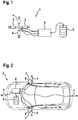
- FIG. 2 schematically shows the use of the camera system 1 in a vehicle 2.
- the first cameras 3 are mounted on movable components 7 of the vehicle 2.
- the first cameras 3 are attached to exterior mirrors of the vehicle 2.
- the second cameras 4 are mounted on a front side and a rear side of the vehicle 2. Via the cameras 3, 4 it is thus possible to detect an entire environment of the vehicle 2. This allows the computing device 6 to generate a virtual plan view or a virtual all-round view around the vehicle 2 from the data of the cameras 3, 4.
- a camera calibration is required for each individual camera 3, 4.
- Such a calibration corresponds to the determination of such data indicating how to process the raw data of the cameras 3, 4 in order to obtain a seamless overall view with consistently the same perspective.
- Such a calibration can be initially created for the second cameras 4, since these cameras are not moved. For the first cameras 3, such an initial creation of a calibration is only possible if the movable components 7 are not moved. Otherwise, the initially created calibration for the first cameras 3 after a movement is no longer valid.
- the computing device 6 is connected in each case to a detection unit 8, wherein each detection unit 8 is designed to detect a movement of the movable component 7. Furthermore, it is provided that a movement model 100, in particular a CAD model 200, of the movable component 7 is stored in the storage device 5.
- the computing device 6 is enabled to determine a current orientation of the movable component 7.
- the computing device 6 On the basis of the movement model 100, in particular of the CAD model 200, it is also possible for the computing device 6 to understand a movement which the movable component 7 must have made in order to reach the current orientation.
- the storage device 5 temporarily stores an installation position and an initial orientation of the first cameras 3 on the movable components.
- a camera calibration for an installation position and an initial alignment of the first cameras 3 is known, while also a deviating from the installation position and the initial orientation current position and orientation of the first camera 3 is known. Based on these data, it is easily possible to correct the camera calibration of the first cameras 3. This is performed by the computing device 6, wherein the corrected camera calibration for each first camera 3 is stored in the storage device 5. Thus, a current camera calibration is available for each first camera 3 at any time in the memory device 5, as a result of which an overall view from the individual images of the first cameras 3 and the second cameras 4 can be generated at any time. This is advantageously independent of a movement of the movable components 7.
- FIG. 3 schematically a method is shown as it is carried out by the computing device 6.
- a step of correcting 10 takes place
- the following input data are collected for this step:
- the reading of the above-described motion model 100, in particular of the CAD model 200 takes place from the memory device 5.
- a CAN signal 500 is advantageously received. having at least one currently detected steering angle 400 of the vehicle 2.
- the information about the joint angle is additionally required. This can be determined via the optical flow of the cameras on the mobile trailer or via a measuring device directly at the joint.
- This data is necessary in particular when the vehicle 2 has a trailer or is provided with a joint, in particular a joint bus, and at least one of the first cameras 3 is movable relative to the second cameras 4 due to the joint or due to the coupling of the trailer ,
- an overall view generating step 11 is performed from sub-images of the first cameras 3 and the second cameras 4. Generating 11 of the overall view is based on the camera calibrations stored in the storage device 5. Since the stored camera calibrations for the first cameras 3 and second cameras 4 are always up-to-date, in particular due to the previously performed correction step 10, generation 11 of the overall view is thus possible at any time, independently of a movement of the movable components 7.
- a detection unit 8 has been used to detect the movement of the movable members 7.
- the camera device 6 it is possible for the camera device 6 to estimate the camera movement of the first cameras 3. The estimation is preferably based on the motion model 100, in particular the CAD model 200.
- the camera system described is in no way limited to two cameras, but unfolds its advantages, especially in systems with more than two cameras, the described calculation rules apply to multiple cameras and then applied an advantageous mutual plausibility of the calculated camera calibrations allow.
Landscapes
- Engineering & Computer Science (AREA)
- Computer Vision & Pattern Recognition (AREA)
- Physics & Mathematics (AREA)
- General Physics & Mathematics (AREA)
- Theoretical Computer Science (AREA)
- Mechanical Engineering (AREA)
- Studio Devices (AREA)
- Closed-Circuit Television Systems (AREA)
- Image Analysis (AREA)
Abstract
Description
- Die vorliegende Erfindung betrifft ein Kamerasystem. Insbesondere ist mit dem Kamerasystem eine Rundumsicht generierbar. Des Weiteren betrifft die Erfindung ein Fahrzeug umfassend ein derartiges Kamerasystem.
- Aus dem Stand der Technik sind Fahrzeuge bekannt, die ein Kamerasystem, aufweisen, wobei mit dem Kamerasystem Bilder rund um das Fahrzeug erfassbar sind. Insbesondere lassen sich virtuelle Draufsichten oder virtuelle Rundumsichten aus dem Kamerasystem erzeugen. Solche Kamerasysteme setzen voraus, dass die einzelnen Kameras entweder nicht an beweglichen Teilen des Fahrzeugs montiert sind oder die beweglichen Teile während des Erfassens der Bilder durch die Kameras nicht bewegt werden. Werden die beweglichen Teile dennoch bewegt, so ist ein Generieren der virtuellen Rundumsicht oder der virtuellen Draufsicht nicht mehr möglich.
- Werden solche Kamerasysteme an Fahrzeugen mit Anhängern oder Gelenkfahrzeugen, wie insbesondere an Gelenkbussen, verwendet, so können Kameras nur an einem einzigen starren Gelenkglied angebracht werden. Dies schränkt die Verwendung solcher Kamerasysteme stark ein.
- Aus der
DE 10 2010 005 638 A1 ist ein Fahrassistenzsystem bekannt, dass eine Vielzahl von Kameras umfasst. Dabei ist vorgesehen, dass zumindest eine Kamera in einem Außenspiegel und damit in einem beweglichen Teil des Fahrzeugs angebracht ist. Die Kamera erfasst ein großräumiges Bild der Umgebung seitlich des Fahrzeugs. Wird der Außenspiegel des Fahrzeugs angeklappt, so wird dies erkannt und eine Änderung der Perspektive der Kamera bestimmt. Anschließend wird das von der Kamera ausgegebene Bild entsprechend bearbeitet, um die Ausgabe des Bildes an die veränderten Aufnahmebedingungen, insbesondere an die veränderte Aufnahmeperspektive, anzupassen. Auf diese Weise lässt sich stets ein korrektes Bild anzeigen, unabhängig davon, in welcher Stellung sich der Außenspiegel befindet. Ein solches Verfahren ermöglicht allerdings nur das Anzeigen einzelner Bilder. Es ist nicht möglich, die Daten der Kamera mit weiteren Kamerabildern zu kombinieren. - Das erfindungsgemäße Kamerasystem ermöglicht vorteilhafterweise ein Anbringen einzelner Kameras an beweglichen Teil eines Fahrzeugs. Allgemein ermöglicht das erfindungsgemäße Kamerasystem mehrere Kameras bereitzustellen, wobei zumindest eine Kamera relativ zu den anderen Kameras bewegbar ist. Dabei lässt sich gleichzeitig eine Kombination von Ansichten aus den Einzelbildern der einzelnen Kameras zu einem Gesamtbild generieren.
- Das Kamerasystem eines Fahrzeugs umfasst zumindest eine erste Kamera und zumindest eine zweite Kamera. Dabei ist vorgesehen, dass die erste Kamera relativ zu der zweiten Kamera bewegbar ist. Dies erfolgt insbesondere unabhängig von einer aktuellen Position und Ausrichtung der beweglichen Kamera. Das Kamerasystem umfasst weiterhin eine Speichervorrichtung zum Speichern jeweils einer Kamerakalibrierung jeder Kamera. Anhand der Kamerakalibrierungen sind Einzelbilder der ersten Kamera und der zweiten Kamera zu einer Gesamtansicht kombinierbar. Insbesondere ist anhand der Kamerakalibrierung eine Vorschrift bekannt, nach welcher Bildbearbeitungsprozesse auf die Rohdaten der jeweiligen Kamera anzuwenden sind, um anschließend eine Abbildung zu erhalten, die hinsichtlich Perspektive und Randstellen bei allen Einzelbildern der einzelnen Kameras gleich ist. So lassen sich die Abbildungen einfach zu einer Gesamtansicht kombinieren. Die Gesamtansicht kann insbesondere eine Rundumsicht oder eine virtuelle Draufsicht sein.
- Weiterhin umfasst das Kamerasystem eine Rechenvorrichtung. Die Rechenvorrichtung ist zum Korrigieren der gespeicherten Kamerakalibrierung der ersten Kamera eingerichtet. Das Korrigieren erfolgt insbesondere aufgrund einer Bewegung der ersten Kamera. Durch die Bewegung der ersten Kamera ist die ursprünglich gespeicherte Kamerakalibrierung nicht mehr auf die Rohdaten der ersten Kamera anwendbar, da sich eine Position und/oder Ausrichtung der ersten Kamera verändert hat. Daher ist dies durch die Rechenvorrichtung zu korrigieren. Außerdem ist die Rechenvorrichtung zum Generieren der Gesamtansicht basierend auf der gespeicherten Kamerakalibrierung eingerichtet. Da für die erste Kamera stets eine aktuelle Kamerakalibrierung vorliegt, die eine aktuelle Position und/oder Ausrichtung berücksichtigt, ist jederzeit das Generieren von Gesamtansichten ermöglicht. Somit erlaubt das Kamerasystem auch das Verwenden von beweglichen Kameras, insbesondere von Kameras, die an beweglichen Teilen des Fahrzeugs angebracht sind, um virtuelle Draufsichten und/oder virtuelle Rundumsicht erzeugen zu können.
- Die Unteransprüche zeigen bevorzugte Weiterbildungen der Erfindung.
- Bevorzugt ist vorgesehen, dass die erste Kamera an einem beweglichen Bauteil des Fahrzeugs anbringbar ist. Dabei ist außerdem vorgesehen, dass die Speichervorrichtung zum Speichern eines Bewegungsmodells des beweglichen Bauteils ausgebildet ist. Die Rechenvorrichtung ist zum Korrigieren der gespeicherten Kamerakalibrierung der ersten Kamera anhand des Bewegungsmodells ausgebildet. Durch das Bewegungsmodell ist somit bestimmbar, welche aktuelle Position und/oder Ausrichtung die erste Kamera aufweist, wenn die Einbauposition der Kamera an dem beweglichen Bauteil bekannt ist. Somit ist insbesondere eine Kamerakalibrierung nicht für unterschiedliche Positionen und/oder Ausrichtung der ersten Kamera zu speichern, vielmehr ist ausreichend die Kamerakalibrierung für eine beliebige Position und Ausrichtung der ersten Kamera durchzuführen und diese zusammen mit der Position und Ausrichtung, an der die Kalibrierung durchgeführt wurde, in der Speichervorrichtung zu speichern. Anhand des Bewegungsmodells und der gespeicherten Position und Ausrichtung lässt sich somit die Kamerakalibrierung für jede beliebige weitere Position und/oder Ausrichtung, die durch das Bewegungsmodell abgebildet ist, korrigieren. Somit ist das Generieren von Gesamtansichten mehrerer Kamerabilder auch bei beweglichen Kameras ermöglicht.
- Die Speichervorrichtung dient bevorzugt zum Speichern einer Einbauposition und einer Initialausrichtung der ersten Kamera an dem beweglichen Bauteil. Insbesondere ist vorgesehen, dass die Kalibrierung der ersten Kamera in der Einbauposition sowie der Initialausrichtung durchgeführt und in der Speichervorrichtung gespeichert ist. Diese Kamerakalibrierung lässt sich somit für jede Bewegung aus der Einbauposition heraus und für jede Ausrichtung von der Initialausrichtung weg korrigieren, bevorzugt anhand des zuvor beschriebenen Bewegungsmodells.
- Das Bewegungsmodell umfasst vorteilhafterweise ein CAD-Modell. Das CAD-Modell ist vorteilhafterweise während der Konstruktion des Fahrzeugs erstellt worden und zeigt insbesondere eine Bewegbarkeit des beweglichen Bauteils. Somit ist zum Erstellen des Bewegungsmodells kein zusätzlicher Aufwand notwendig, da auf bereits vorhandene Daten zurückgegriffen werden kann. Das CAD-Modell weist außerdem bevorzugt die Einbauposition sowie die Initialausrichtung der ersten Kamera auf, sodass diese Daten nicht separat in der Speichervorrichtung gespeichert werden müssen. Durch das Speichern des CAD-Modells innerhalb der Speichervorrichtung ist somit jederzeit eine Korrektur der gespeicherten Kamerakalibrierung der ersten Kamera ermöglicht.
- Vorteilhafterweise ist außerdem vorgesehen, dass das Kamerasystem eine Erfassungseinheit aufweist. Die Erfassungseinheit ist insbesondere ein Sensor. Die Erfassungseinheit dient zum Erfassen der Bewegung des beweglichen Bauteils. Insbesondere zusammen mit dem zuvor beschriebenen Bewegungsmodells besonders vorteilhaft dem CAD-Modell, ist somit eine aktuelle Position und/oder Ausrichtung der ersten Kamera dadurch bestimmbar, dass zunächst die Auslenkung des beweglichen Bauteils aus einer Normalposition anhand der Erfassungseinheit erfasst wird, um diese Bewegung anschließend in dem Bewegungsmodell, insbesondere in dem CAD-Modell, nachzuvollziehen. Somit lässt sich besagte aktuelle Position und/oder Ausrichtung leicht aus dem CAD-Modell berechnen. Mit der berechneten aktuellen Position und/oder Ausrichtung ist dann die Kalibrierung der ersten Kamera korrigierbar. Hierzu ist lediglich zu vergleichen, die aktuelle Position und Ausrichtung von derjenigen Position und Ausrichtung abweicht, der die Kalibrierung durchgeführt wurde.
- Alternativ zu der Erfassungseinheit ist die Rechenvorrichtung vorteilhafterweise zum Abschätzen einer Bewegung des beweglichen Bauteils ausgebildet. Somit ist wiederum bestimmbar, in welcher Position sich das bewegliche Bauteil befindet. Damit ist das Berechnen einer aktuellen Position und/oder Ausrichtung der ersten Kamera analog wie zuvor beschrieben.
- Die Rechenvorrichtung ist insbesondere zum Korrigieren der gespeicherten Kamerakalibrierung der ersten Kamera anhand eines erfassten Gelenkwinkels und/oder eines erfassten Lenkwinkels des Fahrzeugs ausgebildet. Diese Daten lassen sich insbesondere aus einem CAN-Signal ermitteln. Dies ist insbesondere dann vorteilhaft, wenn das Kamerasystem an einem Gelenkfahrzeug oder an einem Fahrzeug mit Anhänger angebracht ist. In diesem Fall ist eine Bewegung der beweglichen Kamera abhängig von dem Lenkwinkel und/oder des Gelenkwinkels.
- Die Rechenvorrichtung ist außerdem bevorzugt zum laufenden Berechnen der Kamerakalibrierung der ersten Kamera und der zweiten Kamera ausgebildet. Das laufende Berechnen der Kamerakalibrierungen erfolgt insbesondere anhand eines optischen Flusses. Außerdem ist die Rechenvorrichtung zum Speichern der neu berechneten Kamerakalibrierung in der ersten Kamera und der zweiten Kamera in der Speichervorrichtung ausgebildet. Somit ist stets sichergestellt, dass eine aktuelle Kamerakalibrierung für jede einzelne Kamera vorliegt. Auf diese Weise lassen sich hochgenaue Gesamtabbildungen durch Kombination der Daten der ersten Kamera und der zweiten Kamera generieren.
- Die Erfindung betrifft weiterhin ein Fahrzeug umfassend ein Kamerasystem wie zuvor beschrieben. Das Fahrzeug ist insbesondere ein Personenkraftfahrzeug oder ein Lastkraftfahrzeuge und kann insbesondere ein Gelenk und/oder einen Anhänger aufweisen. Dabei ist vorgesehen, dass die erste Kamera an einen beweglichen Bauteil des Fahrzeugs angebracht ist, während die zweite Kamera einem starren Bauteil des Fahrzeugs angeordnet ist. Somit ist die erste Kamera relativ zu der zweiten Kamera bewegbar.
- Das bewegliche Bauteil ist bevorzugt ein Außenspiegel und/oder eine Fahrzeugtür. Da mit dem Kamerasystem vorteilhafterweise eine Rundumsicht um das Fahrzeug gewährleistet werden soll, ist somit jede Seite des Fahrzeugs durch mindestens eine Kamera zu erfassen. Dabei ist vorteilhaft, wenn die Kameras jeweils an einer äußeren Extremität des Fahrzeugs angebracht werden. Daher ist vorteilhaft, dass jeweils eine Kamera in einem Außenspiegel des Fahrzeugs angeordnet ist. Somit ist sichergestellt, dass die Seitenbereiche des Fahrzeugs eingesehen werden können. Durch das zuvor beschriebene Kamerasystem ist ein Betreiben der an den Außenspiegeln des Fahrzeugs angebrachten Kameras auch dann möglich, wenn die Außenspiegel eingeklappt oder sonstig bewegt sind.
- Die Erfindung betrifft schließlich ein Verfahren zum Erzeugen einer Gesamtansicht aus Daten einer ersten Kamera und einer zweiten Kamera. Dabei ist vorgesehen, dass die erste Kamera relativ zu der zweiten Kamera bewegbar ist. Das Verfahren umfasst die folgenden Schritte: zunächst erfolgt ein Korrigieren einer gespeicherten Kamerakalibrierung der ersten Kamera. Das Korrigieren erfolgt aufgrund einer Bewegung der ersten Kamera, so dass eine ursprünglich vorhandene Kamerakalibrierung der ersten Kamera nicht mehr gültig ist. Dabei ist vorgesehen, dass, wie zuvor beschrieben, anhand der Kamera Kalibrierungen der ersten Kamera und der zweiten Kamera Einzelbilder der ersten Kamera und der zweiten Kamera zu der Gesamtansicht kombinierbar sind. Anschließend erfolgt ein Generieren der Gesamtansicht basierend auf den gespeicherten Kamerakalibrierungen. Dabei werden insbesondere die zuvor hinsichtlich des Kamerasystems beschriebenen Aspekte auch hinsichtlich des Verfahrens angewandt.
- Nachfolgend wird ein Ausführungsbeispiel der Erfindung unter Bezugnahme auf die begleitenden Zeichnungen im Detail beschrieben. In den Zeichnungen sind:
- Figur 1
- eine schematische Abbildung eines Kamerasystems gemäß einem Ausführungsbeispiel der Erfindung,
- Figur 2
- eine schematische Abbildung eines Fahrzeugs mit einem Kamerasystem gemäß dem Ausführungsbeispiel der Erfindung, und
- Figur 3
- eine schematische Abbildung eines Verfahrens gemäß dem Ausführungsbeispiel der Erfindung.
-
Figur 1 zeigt schematisch eine Abbildung eines Kamerasystems 1 gemäß einem Ausführungsbeispiel der Erfindung. Das Kamerasystem 1 umfasst zwei erste Kameras 3 und zwei zweite Kameras 4. Dabei ist vorgesehen, dass die ersten Kameras 3 relativ zu den zweiten Kameras 4 bewegbar sind. Außerdem ist vorgesehen, dass die Einzelbilder der Kameras 3, 4 zu einem Gesamtbild zusammenfügbar sind. Insbesondere decken die Kameras 3, 4 einen Raumbereich rund um einen Gegenstand vollständig ab. Somit lassen sich aus dem Einzelbilder der Kameras 3, 4 bevorzugt virtuelle Draufsichten oder virtuelle Rundumsichten generieren. - Die Kameras 3, 4 sind mit einer Rechenvorrichtung 6 verbunden. Die Rechenvorrichtung 6 dient insbesondere zum Zusammenfügen der Einzelbilder der Kameras 3, 4 zu der Gesamtansicht. Außerdem weist das Kamerasystem 1 eine Speichervorrichtung 5 auf. In der Speichervorrichtung 5 sind Kamerakalibrierungen der Kameras 3, 4 gespeichert. Anhand der Kamerakalibrierungen lassen sich die Einzelbilder der Kameras 3, 4 zu der Gesamtansicht zusammensetzen.
-
Figur 2 zeigt schematisch die Verwendung des Kamerasystems 1 in einem Fahrzeug 2. Dabei ist vorgesehen, dass die ersten Kameras 3 an beweglichen Bauteilen 7 des Fahrzeugs 2 angebracht sind. Insbesondere sind die ersten Kameras 3 an Außenspiegeln des Fahrzeugs 2 angebracht. Die zweite Kameras 4 sind an einer Frontseite und an einer Rückseite des Fahrzeugs 2 angebracht. Über die Kameras 3, 4 ist somit ermöglicht, ein gesamtes Umfeld des Fahrzeugs 2 zu erfassen. Dies ermöglicht der Rechenvorrichtung 6, eine virtuelle Draufsicht auf oder eine virtuelle Rundumsicht um das Fahrzeug 2 aus den Daten der Kameras 3, 4 zu generieren. - Um die Einzelbilder der Kameras 3, 4 zu einer Gesamtansicht zusammenzusetzen, ist eine Kamerakalibrierung für jede einzelne Kamera 3, 4 benötigt. Eine solche Kalibrierung entspricht der Ermittlung von derartigen Daten, die angeben, wie die Rohdaten der Kameras 3, 4 zu bearbeiten sind, um eine nahtlose Gesamtansicht mit durchgängig gleicher Perspektive zu erhalten. Eine solche Kalibrierung lässt sich für die zweiten Kameras 4 initial erstellen, da diese Kameras nicht bewegt werden. Für die ersten Kameras 3 ist ein solches initiales Erstellen einer Kalibrierung nur dann möglich, wenn die beweglichen Bauteile 7 nicht bewegt werden. Ansonsten ist die initial erstellte Kalibrierung für die ersten Kameras 3 nach einer Bewegung nicht mehr gültig.
- Um die ersten Kameras 3 auch dann verwenden zu können, wenn die beweglichen Bauteile des Fahrzeugs 2 bewegt werden, ist eine Korrektur der Kalibrierung notwendig. Dazu ist vorgesehen, dass die Rechenvorrichtung 6 mit jeweils einer Erfassungseinheit 8 verbunden ist, wobei jede Erfassungseinheit 8 zum Erfassen einer Bewegung des beweglichen Bauteils 7 ausgebildet ist. Weiterhin ist vorgesehen, dass in der Speichervorrichtung 5 ein Bewegungsmodell 100, insbesondere ein CAD-Modell 200, des beweglichen Bauteils 7 gespeichert ist.
- Anhand der Erfassungseinheit 8 ist es der Rechenvorrichtung 6 ermöglicht, eine aktuelle Ausrichtung des beweglichen Bauteils 7 zu bestimmen. Anhand des Bewegungsmodells 100, insbesondere des CAD-Modells 200, ist es der Rechenvorrichtung 6 außerdem ermöglicht, eine Bewegung nachzuvollziehen, die das bewegliche Bauteil 7 durchgeführt haben muss, um in die aktuelle Ausrichtung zu gelangen. Schließlich ist bevorzugt vorgesehen, dass die Speichervorrichtung 5 eine Einbauposition sowie eine Initialausrichtung der ersten Kameras 3 an den beweglichen Bauteilen zwischenspeichert. Somit ist anhand der nachvollzogenen Bewegung des beweglichen Bauteils 7 aufgrund des Bewegungsmodells 100, insbesondere des CAD-Modells 200, ermöglicht, auch eine aktuelle Position und eine aktuelle Ausrichtung der ersten Kameras 3 zu berechnen.
- Auf diese Weise ist einerseits eine Kamerakalibrierung für eine Einbauposition und eine Initialausrichtung der ersten Kameras 3 bekannt, während außerdem eine von der Einbauposition und der Initialausrichtung abweichende aktuelle Position und Ausrichtung der ersten Kameras 3 bekannt ist. Basierend auf diesen Daten ist es einfach möglich, die Kamerakalibrierung der ersten Kameras 3 zu korrigieren. Dies wird von der Rechenvorrichtung 6 durchgeführt, wobei die korrigierte Kamerakalibrierung für jede erste Kamera 3 in der Speichervorrichtung 5 gespeichert wird. Somit steht in der Speichervorrichtung 5 jederzeit eine aktuelle Kamerakalibrierung für jede erste Kamera 3 zur Verfügung, wodurch jederzeit eine Gesamtansicht aus den Einzelbildern der ersten Kameras 3 und der zweiten Kameras 4 erzeugt werden kann. Dies ist vorteilhafterweise unabhängig von einer Bewegung der beweglichen Bauteile 7.
- In
Figur 3 ist schematisch ein Verfahren gezeigt, wie es von der Rechenvorrichtung 6 ausgeführt wird. So erfolgt ein Schritt des Korrigierens 10 der gespeicherten Kamerakalibrierung der ersten Kamera 3. Für diesen Schritt werden folgende Eingangsdaten gesammelt: Zum einen erfolgt das Auslesen des zuvor beschriebenen Bewegungsmodells 100, insbesondere des CAD Modells 200, aus der Speichervorrichtung 5. Zum anderen erfolgt vorteilhafterweise ein Empfang eines CAN-Signals 500, das mindestens einen aktuell erfassten Lenkwinkel 400 des Fahrzeugs 2 aufweist. Im Falle eines Gelenkbetriebs (Anhänger) ist zusätzlich noch die Information über den Gelenkwinkel erforderlich. Dieser kann über den optischen Fluss der Kameras am beweglichen Anhänger oder über eine Messvorrichtung direkt am Gelenk bestimmt werden. Diese Daten sind insbesondere dann notwendig, wenn das Fahrzeug 2 einen Anhänger aufweist oder mit einem Gelenk versehen ist, insbesondere ein Gelenksbus ist, und zumindest eine der ersten Kameras 3 aufgrund des Gelenks oder aufgrund der Koppelung des Anhängers relativ zu den zweiten Kameras 4 bewegbar ist.
Außerdem erfolgt bevorzugt ein Korrigieren der Kamerakalibrierung basierend auf einem optischen Fluss 600. Das Korrigieren der Kamerakalibrierung basierend auf dem optischen Fluss 600 kann vorteilhafterweise für die erste Kamera und die zweite Kammer 4 durchgeführt werden. Auf diese Weise ist stets eine aktualisierte Kamerakalibrierung unabhängig von einer überlagerten Bewegung der Kameras 3, 4 vorhanden. - Nach dem Durchführen des Schritts des Korrigierens 10 erfolgt ein Schritt des Generierens 11 der Gesamtansicht aus dienen Teilbildern der ersten Kameras 3 und der zweiten Kameras 4. Das Generieren 11 der Gesamtansicht basiert auf den in der Speichervorrichtung 5 gespeicherten Kamerakalibrierungen. Da die gespeicherten Kamerakalibrierungen für die ersten Kameras 3 und zweiten Kameras 4 jederzeit aktuell sind, insbesondere aufgrund des zuvor durchgeführten Schritt des Korrigierens 10, ist somit ein Generieren 11 der Gesamtansicht jederzeit möglich, unabhängig von einer Bewegung der beweglichen Bauteile 7.
- Es ist somit ersichtlich, dass durch das Kamerasystem 1 eine Kompensation der Bewegung von einzelnen Kameras ermöglicht ist. Somit steht als Resultat eine Visualisierung einer Gesamtansicht zur Verfügung, wobei die Gesamtansicht aus den Einzelbildern aller vorhandener Kameras 3, 4 generiert wird. Sollten einzelne Bereiche aufgrund der Bewegung der ersten Kameras 3 von keiner der Kameras 3, 4 mehr erfasst werden können, so werden diese Bereiche bevorzugt mit einer leeren und/oder farbigen Fläche innerhalb der Gesamtansicht repräsentiert.
- In dem zuvor beschriebenen Ausführungsbeispiel wurde eine Erfassungseinheit 8 verwendet, um die Bewegung der beweglichen Bauteile 7 zu erfassen. Alternativ oder zusätzlich ist ermöglicht, dass das durch die Rechenvorrichtung 6 eine Kamerabewegung der ersten Kameras 3 abschätzbar ist. Das Schätzen erfolgt bevorzugt basierend auf dem Bewegungsmodell 100, insbesondere dem CAD-Modell 200.
- Besonders vorteilhaft eignet sich das Kamerasystem 1 für die folgenden Anwendungsfälle:
- langer Gelenkbus mit der Kameras 3, 4 an allen beteiligten Gelenken
- Lastkraftwagen mit Anhänger mit Kameras 3, 4 sowohl am Zugfahrzeug als auch am Anhänger
- Pkw mit Anhänger mit Kameras 3, 4 sowohl am Zugfahrzeug als auch am Anhänger
- Das beschriebene Kamerasystem ist in keiner Weise beschränkt auf zwei Kameras, sondern entfaltet seine Vorteile insbesondere bei Systemen mit mehr als zwei Kameras, wobei die beschriebenen Rechenvorschriften für mehrere Kameras gelten und daraufhin angewendet eine vorteilhafte gegenseitige Plausibilisierung der berechneten Kamerakalibrierungen ermöglichen.
- Ferner existiert keine Beschränkung auf eine Teilmenge starrer sowie einer einzigen Teilmenge beweglicher Kameras. Vielmehr ist es möglich, mehrere Teilmengen beweglicher Kameras zu berücksichtigen, wie z.B. ein PKW mit Anhänger, der Kameras an den Außenspiegeln (1. Teilmenge beweglicher Kameras) sowie weitere Kameras am Anhänger aufweist (2. Teilmenge beweglicher Kameras).
Claims (11)
- Kamerasystem (1) für ein Fahrzeug (2) umfassend• zumindest eine erste Kamera (3), die relativ zu zumindest einer zweiten Kamera (4) bewegbar ist,• eine Speichervorrichtung (5) zum Speichern jeweils einer Kamerakalibrierung jeder Kamera (3, 4), wobei anhand der Kamerakalibrierungen Einzelbilder der ersten Kamera (3) und der zweiten Kamera (4) zu einer Gesamtansicht kombinierbar sind, und• eine Rechenvorrichtung (6), eingerichtet zumo Korrigieren (10) der gespeicherten Kamerakalibrierung der ersten Kamera (3) aufgrund einer Bewegung der ersten Kamera (3), undo Generieren (11) der Gesamtansicht basierend auf den gespeicherten Kamerakalibrierungen.
- Kamerasystem (1) nach Anspruch 1, dadurch gekennzeichnet, dass die erste Kamera (3) eingerichtet ist, an einem beweglichen Bauteil (7) des Fahrzeugs (2) angebracht zu werden, wobei die Speichervorrichtung (11) zum Speichern eines Bewegungsmodells (100) des beweglichen Bauteils (7) ausgebildet ist, und wobei die Rechenvorrichtung (6) zum Korrigieren der gespeicherten Kamerakalibrierung der ersten Kamera (3) anhand des Bewegungsmodells (100) ausgebildet ist.
- Kamerasystem (1) nach Anspruch 2, dadurch gekennzeichnet, dass die Speichervorrichtung (11) zum Speichern einer Einbauposition sowie einer Initialausrichtung der ersten Kameras (3) an dem beweglichen Bauteil (7) ausgebildet ist.
- Kamerasystem (1) nach Anspruch 2 oder 3, dadurch gekennzeichnet, dass das Bewegungsmodell ein CAD-Modell (200) umfasst.
- Kamerasystem (1) nach einem der Ansprüche 2 bis 4, gekennzeichnet durch eine Erfassungseinheit (8), insbesondere einen Sensor, zum Erfassen der Bewegung des beweglichen Bauteils (7).
- Kamerasystem (1) nach einem der Ansprüche 2 bis 4, dadurch gekennzeichnet, dass die Rechenvorrichtung (6) zum Abschätzen einer Bewegung des beweglichen Bauteils (7) ausgebildet ist.
- Kamerasystem (1) nach einem der vorhergehenden Ansprüche, dadurch gekennzeichnet, dass die Rechenvorrichtung (6) zum Korrigieren der gespeicherten Kamerakalibrierung der ersten Kamera (3) anhand eines erfassten Gelenkwinkels (300) und/oder eines erfassten Lenkwinkels (400) des Fahrzeugs (2) ausgebildet ist.
- Kamerasystem (1) nach einem der vorhergehenden Ansprüche, dadurch gekennzeichnet, dass die Rechenvorrichtung (6) zum laufenden Berechnen der Kamerakalibrierung der ersten Kamera (3) und der zweiten Kamera (4), insbesondere anhand eines optischen Flusses (600), und zum Speichern der Kamerakalibrierung in der Speichervorrichtung (5) ausgebildet ist.
- Fahrzeug (2) umfassend ein Kamerasystem (1) nach einem der vorhergehenden Ansprüche.
- Fahrzeug (2) umfassend ein Kamerasystem (1) nach Anspruch 2, dadurch gekennzeichnet, dass das bewegliche Bauteil (7) ein Außenspiegel und/oder eine Fahrzeugtür ist.
- Verfahren zum Erzeugen einer Gesamtansicht aus Daten einer ersten Kamera (3) und einer zweiten Kamera (4), wobei die erste Kamera (3) relativ zu der zweiten Kamera (4) bewegbar ist, umfassend die Schritte:• Korrigieren (10) einer gespeicherten Kamerakalibrierung der ersten Kamera (3) aufgrund einer Bewegung der ersten Kamera (3), wobei, anhand der Kamerakalibrierung der ersten Kamera (3) und einer gespeicherten Kamerakalibrierung der zweiten Kamera (4) Einzelbilder der ersten Kamera (3) und der zweiten Kamera (4) zu der Gesamtansicht kombinierbar sind, und• Generieren (11) der Gesamtansicht basierend auf den gespeicherten Kamerakalibrierungen.
Applications Claiming Priority (1)
| Application Number | Priority Date | Filing Date | Title |
|---|---|---|---|
| DE102016218799.6A DE102016218799A1 (de) | 2016-09-29 | 2016-09-29 | Kamerasystem und Fahrzeug umfassend ein derartiges Kamerasystem |
Publications (2)
| Publication Number | Publication Date |
|---|---|
| EP3301646A1 true EP3301646A1 (de) | 2018-04-04 |
| EP3301646B1 EP3301646B1 (de) | 2020-12-16 |
Family
ID=59520788
Family Applications (1)
| Application Number | Title | Priority Date | Filing Date |
|---|---|---|---|
| EP17184427.7A Active EP3301646B1 (de) | 2016-09-29 | 2017-08-02 | Kamerasystem und fahrzeug umfassend ein derartiges kamerasystem |
Country Status (2)
| Country | Link |
|---|---|
| EP (1) | EP3301646B1 (de) |
| DE (1) | DE102016218799A1 (de) |
Cited By (1)
| Publication number | Priority date | Publication date | Assignee | Title |
|---|---|---|---|---|
| WO2020052853A1 (de) * | 2018-09-12 | 2020-03-19 | Robert Bosch Gmbh | Verfahren zur kalibrierung eines erfassungssystems |
Citations (6)
| Publication number | Priority date | Publication date | Assignee | Title |
|---|---|---|---|---|
| JP2008152628A (ja) * | 2006-12-19 | 2008-07-03 | Matsushita Electric Ind Co Ltd | 合成映像表示装置 |
| DE102010005638A1 (de) | 2010-01-25 | 2011-07-28 | Valeo Schalter und Sensoren GmbH, 74321 | Verfahren zum Anzeigen zumindest eines Bildes einer Fahrzeugumgebung auf einer Anzeigeeinrichtung in einem Fahrzeug. Fahrerassistenzeinrichtung für ein Fahrzeugund Fahrzeug mit einer Fahrerassistenzeinrichtung |
| WO2015110207A1 (de) * | 2014-01-24 | 2015-07-30 | Robert Bosch Gmbh | Verfahren und steuergerät zum erkennen einer veränderung eines relativen gierwinkels innerhalb eines stereo-video-systems für ein fahrzeug |
| US20160048966A1 (en) * | 2014-08-13 | 2016-02-18 | Bendix Commercial Vehicle Systems Llc | Learning the distance between cameras for articulated vehicles |
| DE102014218995A1 (de) * | 2014-09-22 | 2016-03-24 | Robert Bosch Gmbh | Verfahren und Vorrichtung zur Bird-View-Darstellung eines Fahrzeuggespanns sowie nachrüstbare Kamera |
| DE102015204949A1 (de) * | 2015-03-19 | 2016-09-22 | Robert Bosch Gmbh | Verfahren zum Erzeugen eines Gesamtbildes einer Fahrzeugumgebung eines Fahrzeuges und entsprechende Vorrichtung |
-
2016
- 2016-09-29 DE DE102016218799.6A patent/DE102016218799A1/de not_active Withdrawn
-
2017
- 2017-08-02 EP EP17184427.7A patent/EP3301646B1/de active Active
Patent Citations (6)
| Publication number | Priority date | Publication date | Assignee | Title |
|---|---|---|---|---|
| JP2008152628A (ja) * | 2006-12-19 | 2008-07-03 | Matsushita Electric Ind Co Ltd | 合成映像表示装置 |
| DE102010005638A1 (de) | 2010-01-25 | 2011-07-28 | Valeo Schalter und Sensoren GmbH, 74321 | Verfahren zum Anzeigen zumindest eines Bildes einer Fahrzeugumgebung auf einer Anzeigeeinrichtung in einem Fahrzeug. Fahrerassistenzeinrichtung für ein Fahrzeugund Fahrzeug mit einer Fahrerassistenzeinrichtung |
| WO2015110207A1 (de) * | 2014-01-24 | 2015-07-30 | Robert Bosch Gmbh | Verfahren und steuergerät zum erkennen einer veränderung eines relativen gierwinkels innerhalb eines stereo-video-systems für ein fahrzeug |
| US20160048966A1 (en) * | 2014-08-13 | 2016-02-18 | Bendix Commercial Vehicle Systems Llc | Learning the distance between cameras for articulated vehicles |
| DE102014218995A1 (de) * | 2014-09-22 | 2016-03-24 | Robert Bosch Gmbh | Verfahren und Vorrichtung zur Bird-View-Darstellung eines Fahrzeuggespanns sowie nachrüstbare Kamera |
| DE102015204949A1 (de) * | 2015-03-19 | 2016-09-22 | Robert Bosch Gmbh | Verfahren zum Erzeugen eines Gesamtbildes einer Fahrzeugumgebung eines Fahrzeuges und entsprechende Vorrichtung |
Non-Patent Citations (1)
| Title |
|---|
| TOBIAS EHLGEN ET AL: "Monitoring surrounding areas of truck-trailer combinations", PROCEEDINGS OF THE 5TH INTERNATIONAL CONFERENCE ON COMPUTER VISION SYSTEMS (ICVS 2007), 21 March 2007 (2007-03-21), BIELEFELD UNIVERSITY, GERMANY, XP055441393, ISBN: 978-3-00-020933-8, DOI: 10.2390/biecoll-icvs2007-76 * |
Cited By (4)
| Publication number | Priority date | Publication date | Assignee | Title |
|---|---|---|---|---|
| WO2020052853A1 (de) * | 2018-09-12 | 2020-03-19 | Robert Bosch Gmbh | Verfahren zur kalibrierung eines erfassungssystems |
| CN112689996A (zh) * | 2018-09-12 | 2021-04-20 | 罗伯特·博世有限公司 | 用于校准检测系统的方法 |
| US11321871B2 (en) | 2018-09-12 | 2022-05-03 | Robert Bosch Gmbh | Method for calibrating a detection system |
| CN112689996B (zh) * | 2018-09-12 | 2024-07-19 | 罗伯特·博世有限公司 | 用于校准检测系统的方法 |
Also Published As
| Publication number | Publication date |
|---|---|
| DE102016218799A1 (de) | 2018-03-29 |
| EP3301646B1 (de) | 2020-12-16 |
Similar Documents
| Publication | Publication Date | Title |
|---|---|---|
| EP3328686B1 (de) | Verfahren und vorrichtung zum anzeigen einer umgebungsszene eines fahrzeuggespanns | |
| DE102017130566B4 (de) | Sichtsystem zur Erfassung einer Fahrzeugumgebung und Spiegelersatzsystem für ein Fahrzeug mit einem Sichtsystem | |
| DE102006003538B3 (de) | Verfahren zum Zusammenfügen mehrerer Bildaufnahmen zu einem Gesamtbild in der Vogelperspektive | |
| EP2805183B1 (de) | Verfahren und vorrichtung zum visualisieren der umgebung eines fahrzeugs | |
| DE102004050149A1 (de) | Verfahren zur Bestimmung von Deichsel- und Trailerwinkel | |
| EP1797534B1 (de) | Verfahren für die erfassung einer optischen struktur | |
| EP2649408B1 (de) | Kamerabasiertes verfahren zur abstandsbestimmung bei einem stehenden fahrzeug, entsprechendes computerprogramm und entsprechendes parkassistenzsystem mit kamera | |
| DE102008045436A1 (de) | Verfahren und Vorrichtung zum Bestimmen eines Knickwinkels zwischen einem Zugfahrzeug und einem Anhänger | |
| EP3012154B1 (de) | Verfahren und vorrichtung zur unterstützung eines fahrers eines fahrzeug-gespanns, insbesondere eines nutzfahrzeug-gespanns | |
| DE102004029130A1 (de) | Verfahren zur Ankupplung eines Anhängers an ein Kraftfahrzeug | |
| DE102021212088B4 (de) | Rückfahrkamerasystem für ein anhängerkupplungssystem und verfahren zum erzeugen einer darstellung in heckrichtung eines fahrzeuges | |
| DE102010006521A1 (de) | Verfahren und Vorrichtung zur Bestimmung des Knickwinkels eines Fahrzeuggespanns | |
| WO2014094941A1 (de) | Kraftfahrzeug mit kamera-monitor-system | |
| DE102008046214A1 (de) | Verfahren und Vorrichtung zur Überwachung einer Umgebung eines Fahrzeuges | |
| DE102009057996A1 (de) | Verfahren zur Bestimmung einer Position einer Kamera mit einem zugehörigen Kamera-Koordinatensystem relativ zu einer Position eines Fahrzeuges oder Fahrzeuggespannes mit einem zugehörigen Fahrzeug-Koordinatensystem | |
| DE102010005638A1 (de) | Verfahren zum Anzeigen zumindest eines Bildes einer Fahrzeugumgebung auf einer Anzeigeeinrichtung in einem Fahrzeug. Fahrerassistenzeinrichtung für ein Fahrzeugund Fahrzeug mit einer Fahrerassistenzeinrichtung | |
| DE102015008887A1 (de) | Verfahren und Vorrichtung zur Kalibrierung eines Headup-Displays in einem Fahrzeug | |
| EP4308418B1 (de) | Verfahren und umfeld-erfassungssystem zum erzeugen eines umgebungsbildes eines mehrgliedrigen gesamtfahrzeugs | |
| DE102016011853A1 (de) | Verfahren zum Generieren von dreidimensionalen Informationen einer Umgebung eines Fahrzeugs | |
| DE102014218995A1 (de) | Verfahren und Vorrichtung zur Bird-View-Darstellung eines Fahrzeuggespanns sowie nachrüstbare Kamera | |
| DE102011010860A1 (de) | Verfahren und Fahrerassistenzsystem zum Anzeigen von Bildern in einem Kraftfahrzeug sowie Kraftfahrzeug | |
| DE102008030104A1 (de) | Verfahren und Vorrichtung zur Überwachung einer Umgebung eines Fahrzeuges | |
| EP2500216A1 (de) | Verfahren und Vorrichtung für ein bildgebendes Fahrerassistenzsystem | |
| DE102007016055A1 (de) | Fahrzeugumgebungsüberwachungsvorrichtung und Fahrzeugumgebungsüberwachungs-Videoanzeigeverfahren | |
| DE102018207756B3 (de) | Verfahren zum Bereitstellen einer vorgegebenen Abbildung von einer Fahrzeugumgebung eines Kraftfahrzeugs, Kamerasystem für ein Kraftfahrzeug sowie Kraftfahrzeug mit einem derartigen Kamerasystem |
Legal Events
| Date | Code | Title | Description |
|---|---|---|---|
| PUAI | Public reference made under article 153(3) epc to a published international application that has entered the european phase |
Free format text: ORIGINAL CODE: 0009012 |
|
| STAA | Information on the status of an ep patent application or granted ep patent |
Free format text: STATUS: THE APPLICATION HAS BEEN PUBLISHED |
|
| AK | Designated contracting states |
Kind code of ref document: A1 Designated state(s): AL AT BE BG CH CY CZ DE DK EE ES FI FR GB GR HR HU IE IS IT LI LT LU LV MC MK MT NL NO PL PT RO RS SE SI SK SM TR |
|
| AX | Request for extension of the european patent |
Extension state: BA ME |
|
| STAA | Information on the status of an ep patent application or granted ep patent |
Free format text: STATUS: REQUEST FOR EXAMINATION WAS MADE |
|
| 17P | Request for examination filed |
Effective date: 20181004 |
|
| RBV | Designated contracting states (corrected) |
Designated state(s): AL AT BE BG CH CY CZ DE DK EE ES FI FR GB GR HR HU IE IS IT LI LT LU LV MC MK MT NL NO PL PT RO RS SE SI SK SM TR |
|
| STAA | Information on the status of an ep patent application or granted ep patent |
Free format text: STATUS: EXAMINATION IS IN PROGRESS |
|
| RAP1 | Party data changed (applicant data changed or rights of an application transferred) |
Owner name: ROBERT BOSCH GMBH |
|
| 17Q | First examination report despatched |
Effective date: 20200428 |
|
| GRAP | Despatch of communication of intention to grant a patent |
Free format text: ORIGINAL CODE: EPIDOSNIGR1 |
|
| STAA | Information on the status of an ep patent application or granted ep patent |
Free format text: STATUS: GRANT OF PATENT IS INTENDED |
|
| RIC1 | Information provided on ipc code assigned before grant |
Ipc: B60R 11/04 20060101ALI20200904BHEP Ipc: G06T 7/80 20170101AFI20200904BHEP |
|
| INTG | Intention to grant announced |
Effective date: 20200930 |
|
| GRAS | Grant fee paid |
Free format text: ORIGINAL CODE: EPIDOSNIGR3 |
|
| GRAA | (expected) grant |
Free format text: ORIGINAL CODE: 0009210 |
|
| STAA | Information on the status of an ep patent application or granted ep patent |
Free format text: STATUS: THE PATENT HAS BEEN GRANTED |
|
| AK | Designated contracting states |
Kind code of ref document: B1 Designated state(s): AL AT BE BG CH CY CZ DE DK EE ES FI FR GB GR HR HU IE IS IT LI LT LU LV MC MK MT NL NO PL PT RO RS SE SI SK SM TR |
|
| REG | Reference to a national code |
Ref country code: GB Ref legal event code: FG4D Free format text: NOT ENGLISH |
|
| REG | Reference to a national code |
Ref country code: IE Ref legal event code: FG4D Free format text: LANGUAGE OF EP DOCUMENT: GERMAN |
|
| REG | Reference to a national code |
Ref country code: DE Ref legal event code: R096 Ref document number: 502017008672 Country of ref document: DE |
|
| REG | Reference to a national code |
Ref country code: AT Ref legal event code: REF Ref document number: 1346271 Country of ref document: AT Kind code of ref document: T Effective date: 20210115 |
|
| PG25 | Lapsed in a contracting state [announced via postgrant information from national office to epo] |
Ref country code: GR Free format text: LAPSE BECAUSE OF FAILURE TO SUBMIT A TRANSLATION OF THE DESCRIPTION OR TO PAY THE FEE WITHIN THE PRESCRIBED TIME-LIMIT Effective date: 20210317 Ref country code: FI Free format text: LAPSE BECAUSE OF FAILURE TO SUBMIT A TRANSLATION OF THE DESCRIPTION OR TO PAY THE FEE WITHIN THE PRESCRIBED TIME-LIMIT Effective date: 20201216 Ref country code: RS Free format text: LAPSE BECAUSE OF FAILURE TO SUBMIT A TRANSLATION OF THE DESCRIPTION OR TO PAY THE FEE WITHIN THE PRESCRIBED TIME-LIMIT Effective date: 20201216 Ref country code: NO Free format text: LAPSE BECAUSE OF FAILURE TO SUBMIT A TRANSLATION OF THE DESCRIPTION OR TO PAY THE FEE WITHIN THE PRESCRIBED TIME-LIMIT Effective date: 20210316 |
|
| REG | Reference to a national code |
Ref country code: NL Ref legal event code: MP Effective date: 20201216 |
|
| PG25 | Lapsed in a contracting state [announced via postgrant information from national office to epo] |
Ref country code: SE Free format text: LAPSE BECAUSE OF FAILURE TO SUBMIT A TRANSLATION OF THE DESCRIPTION OR TO PAY THE FEE WITHIN THE PRESCRIBED TIME-LIMIT Effective date: 20201216 Ref country code: BG Free format text: LAPSE BECAUSE OF FAILURE TO SUBMIT A TRANSLATION OF THE DESCRIPTION OR TO PAY THE FEE WITHIN THE PRESCRIBED TIME-LIMIT Effective date: 20210316 Ref country code: LV Free format text: LAPSE BECAUSE OF FAILURE TO SUBMIT A TRANSLATION OF THE DESCRIPTION OR TO PAY THE FEE WITHIN THE PRESCRIBED TIME-LIMIT Effective date: 20201216 |
|
| PG25 | Lapsed in a contracting state [announced via postgrant information from national office to epo] |
Ref country code: NL Free format text: LAPSE BECAUSE OF FAILURE TO SUBMIT A TRANSLATION OF THE DESCRIPTION OR TO PAY THE FEE WITHIN THE PRESCRIBED TIME-LIMIT Effective date: 20201216 Ref country code: HR Free format text: LAPSE BECAUSE OF FAILURE TO SUBMIT A TRANSLATION OF THE DESCRIPTION OR TO PAY THE FEE WITHIN THE PRESCRIBED TIME-LIMIT Effective date: 20201216 |
|
| REG | Reference to a national code |
Ref country code: LT Ref legal event code: MG9D |
|
| PG25 | Lapsed in a contracting state [announced via postgrant information from national office to epo] |
Ref country code: EE Free format text: LAPSE BECAUSE OF FAILURE TO SUBMIT A TRANSLATION OF THE DESCRIPTION OR TO PAY THE FEE WITHIN THE PRESCRIBED TIME-LIMIT Effective date: 20201216 Ref country code: CZ Free format text: LAPSE BECAUSE OF FAILURE TO SUBMIT A TRANSLATION OF THE DESCRIPTION OR TO PAY THE FEE WITHIN THE PRESCRIBED TIME-LIMIT Effective date: 20201216 Ref country code: SM Free format text: LAPSE BECAUSE OF FAILURE TO SUBMIT A TRANSLATION OF THE DESCRIPTION OR TO PAY THE FEE WITHIN THE PRESCRIBED TIME-LIMIT Effective date: 20201216 Ref country code: LT Free format text: LAPSE BECAUSE OF FAILURE TO SUBMIT A TRANSLATION OF THE DESCRIPTION OR TO PAY THE FEE WITHIN THE PRESCRIBED TIME-LIMIT Effective date: 20201216 Ref country code: SK Free format text: LAPSE BECAUSE OF FAILURE TO SUBMIT A TRANSLATION OF THE DESCRIPTION OR TO PAY THE FEE WITHIN THE PRESCRIBED TIME-LIMIT Effective date: 20201216 Ref country code: RO Free format text: LAPSE BECAUSE OF FAILURE TO SUBMIT A TRANSLATION OF THE DESCRIPTION OR TO PAY THE FEE WITHIN THE PRESCRIBED TIME-LIMIT Effective date: 20201216 Ref country code: PT Free format text: LAPSE BECAUSE OF FAILURE TO SUBMIT A TRANSLATION OF THE DESCRIPTION OR TO PAY THE FEE WITHIN THE PRESCRIBED TIME-LIMIT Effective date: 20210416 |
|
| PG25 | Lapsed in a contracting state [announced via postgrant information from national office to epo] |
Ref country code: PL Free format text: LAPSE BECAUSE OF FAILURE TO SUBMIT A TRANSLATION OF THE DESCRIPTION OR TO PAY THE FEE WITHIN THE PRESCRIBED TIME-LIMIT Effective date: 20201216 |
|
| REG | Reference to a national code |
Ref country code: DE Ref legal event code: R097 Ref document number: 502017008672 Country of ref document: DE |
|
| PG25 | Lapsed in a contracting state [announced via postgrant information from national office to epo] |
Ref country code: IS Free format text: LAPSE BECAUSE OF FAILURE TO SUBMIT A TRANSLATION OF THE DESCRIPTION OR TO PAY THE FEE WITHIN THE PRESCRIBED TIME-LIMIT Effective date: 20210416 |
|
| PLBE | No opposition filed within time limit |
Free format text: ORIGINAL CODE: 0009261 |
|
| STAA | Information on the status of an ep patent application or granted ep patent |
Free format text: STATUS: NO OPPOSITION FILED WITHIN TIME LIMIT |
|
| PG25 | Lapsed in a contracting state [announced via postgrant information from national office to epo] |
Ref country code: IT Free format text: LAPSE BECAUSE OF FAILURE TO SUBMIT A TRANSLATION OF THE DESCRIPTION OR TO PAY THE FEE WITHIN THE PRESCRIBED TIME-LIMIT Effective date: 20201216 Ref country code: AL Free format text: LAPSE BECAUSE OF FAILURE TO SUBMIT A TRANSLATION OF THE DESCRIPTION OR TO PAY THE FEE WITHIN THE PRESCRIBED TIME-LIMIT Effective date: 20201216 |
|
| 26N | No opposition filed |
Effective date: 20210917 |
|
| PG25 | Lapsed in a contracting state [announced via postgrant information from national office to epo] |
Ref country code: DK Free format text: LAPSE BECAUSE OF FAILURE TO SUBMIT A TRANSLATION OF THE DESCRIPTION OR TO PAY THE FEE WITHIN THE PRESCRIBED TIME-LIMIT Effective date: 20201216 |
|
| PG25 | Lapsed in a contracting state [announced via postgrant information from national office to epo] |
Ref country code: ES Free format text: LAPSE BECAUSE OF FAILURE TO SUBMIT A TRANSLATION OF THE DESCRIPTION OR TO PAY THE FEE WITHIN THE PRESCRIBED TIME-LIMIT Effective date: 20201216 |
|
| PG25 | Lapsed in a contracting state [announced via postgrant information from national office to epo] |
Ref country code: SI Free format text: LAPSE BECAUSE OF FAILURE TO SUBMIT A TRANSLATION OF THE DESCRIPTION OR TO PAY THE FEE WITHIN THE PRESCRIBED TIME-LIMIT Effective date: 20201216 |
|
| REG | Reference to a national code |
Ref country code: CH Ref legal event code: PL |
|
| PG25 | Lapsed in a contracting state [announced via postgrant information from national office to epo] |
Ref country code: MC Free format text: LAPSE BECAUSE OF FAILURE TO SUBMIT A TRANSLATION OF THE DESCRIPTION OR TO PAY THE FEE WITHIN THE PRESCRIBED TIME-LIMIT Effective date: 20201216 |
|
| REG | Reference to a national code |
Ref country code: BE Ref legal event code: MM Effective date: 20210831 |
|
| PG25 | Lapsed in a contracting state [announced via postgrant information from national office to epo] |
Ref country code: LI Free format text: LAPSE BECAUSE OF NON-PAYMENT OF DUE FEES Effective date: 20210831 Ref country code: CH Free format text: LAPSE BECAUSE OF NON-PAYMENT OF DUE FEES Effective date: 20210831 |
|
| PG25 | Lapsed in a contracting state [announced via postgrant information from national office to epo] |
Ref country code: IS Free format text: LAPSE BECAUSE OF FAILURE TO SUBMIT A TRANSLATION OF THE DESCRIPTION OR TO PAY THE FEE WITHIN THE PRESCRIBED TIME-LIMIT Effective date: 20210416 Ref country code: LU Free format text: LAPSE BECAUSE OF NON-PAYMENT OF DUE FEES Effective date: 20210802 |
|
| PG25 | Lapsed in a contracting state [announced via postgrant information from national office to epo] |
Ref country code: IE Free format text: LAPSE BECAUSE OF NON-PAYMENT OF DUE FEES Effective date: 20210802 Ref country code: BE Free format text: LAPSE BECAUSE OF NON-PAYMENT OF DUE FEES Effective date: 20210831 |
|
| PG25 | Lapsed in a contracting state [announced via postgrant information from national office to epo] |
Ref country code: HU Free format text: LAPSE BECAUSE OF FAILURE TO SUBMIT A TRANSLATION OF THE DESCRIPTION OR TO PAY THE FEE WITHIN THE PRESCRIBED TIME-LIMIT; INVALID AB INITIO Effective date: 20170802 |
|
| PG25 | Lapsed in a contracting state [announced via postgrant information from national office to epo] |
Ref country code: CY Free format text: LAPSE BECAUSE OF FAILURE TO SUBMIT A TRANSLATION OF THE DESCRIPTION OR TO PAY THE FEE WITHIN THE PRESCRIBED TIME-LIMIT Effective date: 20201216 |
|
| REG | Reference to a national code |
Ref country code: AT Ref legal event code: MM01 Ref document number: 1346271 Country of ref document: AT Kind code of ref document: T Effective date: 20220802 |
|
| PG25 | Lapsed in a contracting state [announced via postgrant information from national office to epo] |
Ref country code: AT Free format text: LAPSE BECAUSE OF NON-PAYMENT OF DUE FEES Effective date: 20220802 |
|
| PG25 | Lapsed in a contracting state [announced via postgrant information from national office to epo] |
Ref country code: MK Free format text: LAPSE BECAUSE OF FAILURE TO SUBMIT A TRANSLATION OF THE DESCRIPTION OR TO PAY THE FEE WITHIN THE PRESCRIBED TIME-LIMIT Effective date: 20201216 |
|
| PG25 | Lapsed in a contracting state [announced via postgrant information from national office to epo] |
Ref country code: MT Free format text: LAPSE BECAUSE OF FAILURE TO SUBMIT A TRANSLATION OF THE DESCRIPTION OR TO PAY THE FEE WITHIN THE PRESCRIBED TIME-LIMIT Effective date: 20201216 |
|
| PGFP | Annual fee paid to national office [announced via postgrant information from national office to epo] |
Ref country code: GB Payment date: 20240822 Year of fee payment: 8 |
|
| PGFP | Annual fee paid to national office [announced via postgrant information from national office to epo] |
Ref country code: FR Payment date: 20240823 Year of fee payment: 8 |
|
| REG | Reference to a national code |
Ref country code: DE Ref legal event code: R084 Ref document number: 502017008672 Country of ref document: DE |
|
| PG25 | Lapsed in a contracting state [announced via postgrant information from national office to epo] |
Ref country code: TR Free format text: LAPSE BECAUSE OF FAILURE TO SUBMIT A TRANSLATION OF THE DESCRIPTION OR TO PAY THE FEE WITHIN THE PRESCRIBED TIME-LIMIT Effective date: 20201216 |
|
| PGFP | Annual fee paid to national office [announced via postgrant information from national office to epo] |
Ref country code: DE Payment date: 20251021 Year of fee payment: 9 |