EP3301416B1 - Thermographischer temperaturfühler - Google Patents
Thermographischer temperaturfühler Download PDFInfo
- Publication number
- EP3301416B1 EP3301416B1 EP17192356.8A EP17192356A EP3301416B1 EP 3301416 B1 EP3301416 B1 EP 3301416B1 EP 17192356 A EP17192356 A EP 17192356A EP 3301416 B1 EP3301416 B1 EP 3301416B1
- Authority
- EP
- European Patent Office
- Prior art keywords
- thermographic
- light pipe
- temperature
- temperature sensor
- sheath
- Prior art date
- Legal status (The legal status is an assumption and is not a legal conclusion. Google has not performed a legal analysis and makes no representation as to the accuracy of the status listed.)
- Active
Links
Images




Classifications
-
- G—PHYSICS
- G01—MEASURING; TESTING
- G01J—MEASUREMENT OF INTENSITY, VELOCITY, SPECTRAL CONTENT, POLARISATION, PHASE OR PULSE CHARACTERISTICS OF INFRARED, VISIBLE OR ULTRAVIOLET LIGHT; COLORIMETRY; RADIATION PYROMETRY
- G01J5/00—Radiation pyrometry, e.g. infrared or optical thermometry
-
- G—PHYSICS
- G01—MEASURING; TESTING
- G01K—MEASURING TEMPERATURE; MEASURING QUANTITY OF HEAT; THERMALLY-SENSITIVE ELEMENTS NOT OTHERWISE PROVIDED FOR
- G01K11/00—Measuring temperature based upon physical or chemical changes not covered by groups G01K3/00, G01K5/00, G01K7/00 or G01K9/00
- G01K11/20—Measuring temperature based upon physical or chemical changes not covered by groups G01K3/00, G01K5/00, G01K7/00 or G01K9/00 using thermoluminescent materials
-
- G—PHYSICS
- G01—MEASURING; TESTING
- G01K—MEASURING TEMPERATURE; MEASURING QUANTITY OF HEAT; THERMALLY-SENSITIVE ELEMENTS NOT OTHERWISE PROVIDED FOR
- G01K11/00—Measuring temperature based upon physical or chemical changes not covered by groups G01K3/00, G01K5/00, G01K7/00 or G01K9/00
- G01K11/32—Measuring temperature based upon physical or chemical changes not covered by groups G01K3/00, G01K5/00, G01K7/00 or G01K9/00 using changes in transmittance, scattering or luminescence in optical fibres
- G01K11/3206—Measuring temperature based upon physical or chemical changes not covered by groups G01K3/00, G01K5/00, G01K7/00 or G01K9/00 using changes in transmittance, scattering or luminescence in optical fibres at discrete locations in the fibre, e.g. using Bragg scattering
- G01K11/3213—Measuring temperature based upon physical or chemical changes not covered by groups G01K3/00, G01K5/00, G01K7/00 or G01K9/00 using changes in transmittance, scattering or luminescence in optical fibres at discrete locations in the fibre, e.g. using Bragg scattering using changes in luminescence, e.g. at the distal end of the fibres
-
- G—PHYSICS
- G01—MEASURING; TESTING
- G01K—MEASURING TEMPERATURE; MEASURING QUANTITY OF HEAT; THERMALLY-SENSITIVE ELEMENTS NOT OTHERWISE PROVIDED FOR
- G01K1/00—Details of thermometers not specially adapted for particular types of thermometer
- G01K1/08—Protective devices, e.g. casings
-
- G—PHYSICS
- G01—MEASURING; TESTING
- G01M—TESTING STATIC OR DYNAMIC BALANCE OF MACHINES OR STRUCTURES; TESTING OF STRUCTURES OR APPARATUS, NOT OTHERWISE PROVIDED FOR
- G01M15/00—Testing of engines
- G01M15/04—Testing internal-combustion engines
- G01M15/10—Testing internal-combustion engines by monitoring exhaust gases or combustion flame
- G01M15/102—Testing internal-combustion engines by monitoring exhaust gases or combustion flame by monitoring exhaust gases
- G01M15/108—Testing internal-combustion engines by monitoring exhaust gases or combustion flame by monitoring exhaust gases using optical methods
Definitions
- thermographic temperature sensors in particular to a thermographic temperature probe for use in high temperature environments.
- Gas turbine systems typically include at least one gas turbine engine having a compressor, a combustor, and a turbine.
- the combustor is configured to combust a mixture of fuel and compressed air to generate hot combustion gases, which, in turn, drive blades of the turbine.
- a temperature of exhaust gas produced by the gas turbine engine may vary depending on a configuration of the gas turbine engine, the fuel, and/or fuel-to-air ratios, among other combustion parameters.
- the temperature of the exhaust gas may be estimated, or may be measured using thermocouples.
- the temperature of the exhaust gas may be at temperature ranges that may be difficult to measure using existing temperature measurement techniques (e.g., applications). Therefore, it may be desirable to improve existing temperature measurement techniques for determining exhaust gas temperatures.
- HONG H Y-P ET AL "Influence of local-site symmetry on fluorescence lifetime in high-Nd-concentration laser materials", MATERIALS RESEARCHBULLETIN, ELSEVIER, KIDLINGTON, GB, vol. 11, no. 5, 1 May 1976, pages 461-468, XP024080674, ISSN: 0025-5408, DOI: 10.1016/0025-5408(76)90224-5 describes the influence of local-site symmetry on fluorescence lifetime in high-Nd-concentration laser materials.
- US 2015/276506 describes a fiber optic temperature sensing system incorporating a thermal probe which utilizes a phosphor in the form of a microsphere.
- thermographic temperature sensor as defined by claim 1
- thermographic temperature sensor as defined by claim 10
- Present embodiments are generally directed toward system and methods for measuring fluid temperatures (e.g., exhaust gas temperature).
- one or more gas turbine engines may combust a fuel/oxidant mixture to produce combustion gases (e.g., exhaust gases) for driving one or more turbine stages, each having a plurality of blades.
- combustion gases e.g., exhaust gases
- a temperature of the exhaust gas resulting from the combustion process may vary.
- Evaluating a temperature of the exhaust gas generated by various gas turbine engine configurations and operating (e.g., combustion) parameters may facilitate design of system components downstream of a combustor of the gas turbine engine. Additionally, in existing gas turbine engines, it may be desirable to monitor the exhaust gas temperatures to monitor combustion parameters of the gas turbine system.
- direct measurement of the temperature of the exhaust gas produced in the gas turbine engine during combustion also allows for a more direct evaluation of operational parameters of the gas turbine system when adjusted.
- other operating parameters may be adjusted in response to these direct temperature measurements. For example, an amount of cooling fluid (e.g., air) used to cool system components downstream of the gas turbine engine may be adjusted and/or redirected to other system components based on such temperature measurements.
- certain gas turbine engine models may generate an exhaust gas having a temperature that may not require a substantial amount of cooling fluid to cool the exhaust gas and/or downstream system components (e.g., system components downstream of a combustor of the gas turbine engine) in contact with the exhaust gas.
- an amount of air generally used to cool the exhaust gas and/or downstream system components downstream of the combustor may be decreased compared to gas turbine engines that generate exhaust gases having temperatures above a desired threshold. Accordingly, at least a portion of the air used to cool the exhaust gas and/or system components downstream of the combustor may be redirected to the combustor of the gas turbine engine or other system processes that may utilized the air. Moreover, knowing the temperature of the exhaust gas exiting the gas turbine engine may facilitate selection of materials used to fabricate the system components downstream of the gas turbine engine.
- exhaust gas temperatures may be evaluated in a combustion testing laboratory using a combustion testing apparatus that is representative of an engine configuration associated with a particular gas turbine engine model.
- the combustion testing apparatus may simulate performance of the gas turbine engine model that may be incorporated into a particular gas turbine system.
- One way of measuring exhaust gas temperatures in the combustion testing apparatus is with a thermocouple.
- Type B thermocouples may be used with the combustion testing apparatus to directly measure the temperature of the exhaust gas exiting a combustor of the combustion testing apparatus.
- Thermocouples, such as Type B thermocouples are manufactured from metallic materials such as a mixture of platinum (Pt) and rhodium (Rh).
- Type B thermocouples are suitable for measuring fluid temperatures up to approximately 1700 °C, which is the highest temperature limit for thermocouples.
- certain large frame heavy duty gas turbine engines having a megawatt range greater than 50 megawatts (MW) e.g., non-Areo derivative gas turbine engines
- MW megawatts
- non-Areo derivative gas turbine engines may generate exhaust gas having temperatures in excess of 1700 °C.
- the thermocouples used to measure the exhaust gas temperature in the combustion testing apparatus are generally replaced after a single use, thereby increasing the overall cost of combustion testing. The measurements using these thermocouples may also be inaccurate at such temperatures.
- thermographic temperature sensors that use thermographic materials (e.g., rare-earth- or transition metal-doped ceramic phosphors, also known as thermographic phosphors) may be used to replace thermocouples for high temperature measurement applications.
- the thermographic temperature sensors may include non-metallic refractory materials (e.g., ceramics) that may be more appropriate for use in temperature sensing applications that are unsuitable for thermocouples.
- Thermographic phosphors may have a temperature threshold that is above 1700 °C. Therefore, using thermographic temperature sensors for measuring exhaust gas temperatures in the combustion testing apparatus or any other high temperature environment may mitigate the undesirable costs associated with replacement of thermocouples used to measure high temperature fluids (e.g., exhaust gas) after each use. Additionally, the thermographic temperature sensors may provide a more accurate temperature measurement compared to traditional thermocouples at temperatures above 1700 °C. Generally, thermographic phosphors are coated onto surfaces of interest to indirectly measure a temperature of a fluid (e.g., exhaust gas) based on the temperature of the surface that is in contact with the fluid.
- a fluid e.g., exhaust gas
- thermographic temperature sensor that may be immersed within a fluid of interest to directly measure the temperature of the fluid of interest (e.g., exhaust gas). Accordingly, present embodiments include a thermographic temperature probe that may be used to directly measure the temperature of fluids of interest, even when the temperature of the fluid is greater than the suitable temperature range for traditional thermocouples.
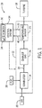
- FIG. 1 is a schematic diagram of an example gas turbine system 10 that includes a gas turbine engine 12 having a combustor 14 and a turbine 16.
- the gas turbine system 10 may be all or part of a power generation system.
- the gas turbine system 10 may be part of a laboratory combustion testing apparatus.
- the gas turbine system 10 also includes one or more thermographic temperature sensors 20 positioned along a flow path 22 of an exhaust gas 24 generated in the combustor 14.
- the one or more thermographic temperature sensors 20 are located between the combustor 14 and the turbine 16.
- the one or more thermographic temperature sensors 20 may be located downstream of the turbine 16 or at any other suitable location within the gas turbine system 10.
- the gas turbine system 10 may use liquid or gas fuel, such as natural gas and/or a hydrogen-rich synthetic gas, to run the gas turbine system 10.
- fuel 28 and air 30 e.g., compressed air
- one or more fuel nozzles may inject a fuel-air mixture into the combustor 14 in a suitable ratio for desired combustion, emissions, fuel consumption, power output, and so forth.
- the combustion of the fuel 28 and the air 30 may generate the hot pressurized exhaust gas 24 (e.g., combustion gases), which may then be utilized to drive one or more turbine blades within the turbine 16.
- the combustion gases e.g., the exhaust gas 24
- the turbine 16 may not necessarily be in place.
- the one or more thermographic temperature sensors 20 may be used to measure the temperature of the exhaust gas 24 within the gas turbine system 10.
- the one or more thermographic temperature sensors 20 may measure the temperature of the exhaust gas 24 within or immediately downstream of the combustor 14, upstream of the turbine 16 (e.g., between the combustor 14 and the turbine 16), downstream of the turbine 16 (e.g., in an exhaust duct), or any other suitable location within the gas turbine system 10.
- the temperature of the exhaust gas 24 may be above a temperature (e.g., 1700 °C) suitable for using existing thermocouples.
- thermocouples are generally used to measure the temperature of the exhaust gas generated in combustion systems (e.g., the gas turbine system 10, combustion testing apparatus, etc.).
- Type B thermocouples which have the highest temperature tolerance compared to other types of thermocouples, are not suitable for measuring temperatures of fluids (e.g., the exhaust gas 24) that are above 1700 °C.
- the metallic materials used to manufacture thermocouples may not be sufficiently durable to withstand fluid temperatures exceeding 1700 °C.
- Thermographic phosphor-based temperature sensors of the present disclosure may be manufactured from non-metallic refractory materials that may be more durable and/or resistant to fluid temperatures above 1700 °C compared to the metal-based thermocouple temperature sensors.
- thermographic phosphor disposed within a temperature probe that may be inserted into a flow path of the fluid of interest.
- the thermographic phosphor may be used to directly measure the temperature of the fluid of interest rather than the temperature of the surface that may be exposed to the fluid.
- the one or more thermographic temperature sensors 20 may include a temperature probe having thermographic phosphors such as rare-earth- or transition metal-doped crystals that may be used to directly measure the temperature of the exhaust gas 24.
- the thermographic phosphors may be excited with optical energy, resulting in phosphorescence of the thermographic phosphors. Certain characteristics of the phosphorescence may be a function of the temperature of the fluid.
- the phosphorescence of the thermographic phosphors may be measured over time to determine the temperature of the exhaust gas 24.
- the illustrated gas turbine system 10 also includes a control system 34 configured to control operation of the gas turbine system 10 and/or determine the temperature of the exhaust gas 24 based on the temperature measurements obtained from the one or more temperature sensors 20.
- the control system 34 may independently control operation of the gas turbine system 10 by electrically communicating with sensors, control valves, and pumps, or other flow adjusting features throughout the gas turbine system 10.
- the control system 34 may include a distributed control system (DCS) or any computer-based workstation that is fully or partially automated.
- the control system 34 can be any device employing a general purpose computer or an application-specific device, both of which may generally include memory circuitry 36 storing one or more instructions for controlling operation of the gas turbine system 10, determining combustion parameters, and determining a temperature of the exhaust gas 24, among others.
- control system 34 may include separate controllers for controlling the gas turbine engine 12 and the temperature sensor 20.
- the temperature sensor 20 includes its own controller.
- a temperature controller may be disposed within a housing of the temperature sensor 20. The temperature controller may communicate with the control system 34 to control operational parameters of the gas turbine system 10 based on the temperature of the exhaust gas 24.
- control system 34 of the gas turbine system 10 may perform functions such as notifying the operators of the system 10 to adjust operating parameters, perform service, or otherwise cease operating the system 10.
- control system 34 may also implement corrective actions specifically relating to adjusting fuel/air ratios, exhaust temperature, flow rates of cooling air, or any other suitable parameter of the gas turbine system 10.
- control system 34 may use information provided via one or more input signals 40 from one or more sensors (e.g., the temperature sensor 20) of the gas turbine system 10 to execute instructions or code contained on the memory 36 and generate one or more output signals 42 to various flow control devices to control a flow of fluids (e.g., the fuel 28 and the air 30) within the gas turbine system 10.
- control system 34 may control operation of optical components of the one or more temperature sensors 20 to determine the temperature of the exhaust gas 24, as discussed in further detail below with reference to FIG. 3 .
- the one or more thermographic temperature sensors 20 may measure the temperature of the exhaust gas 24 in the gas turbine system 10 within or downstream of the combustor 14 (e.g., along a flow path of the exhaust gas 24 between the combustor 14 and the turbine 16).
- the gas turbine system 10 may include a manifold that may facilitate placement of the one or more temperature sensors 20 along (within) the flow path of the exhaust gas 24.
- FIG. 2 illustrates a temperature manifold 50 (e.g., a temperature rake) that may be used in the gas turbine system 10 to facilitate direct measurement of the temperature of the exhaust gas 24 with the one or more thermographic sensors 20.
- the temperature manifold 50 includes a body 52 having a plurality of channels 54 sized to accommodate the one or more temperature sensors 20.
- Each channel of the plurality of channels 54 extends from a manifold end 56 toward a manifold sidewall 58, and terminates in an opening 62 on the manifold sidewall 58.
- the openings 62 may be disposed at progressively increasing distances away from the manifold end 56.
- each sensor of the one or more thermographic temperature sensors 20 may be inserted into a port 70 of the respective channel of the plurality of channels 54 disposed adjacent to the manifold end 56.
- the channel of the plurality of channels 54 may guide the one or more thermographic temperature sensors 20 through the temperature manifold 50 and through the opening 62.
- a tip 72 of the one or more temperature sensors 20 may extend a distance away from the sidewall 58 and into the flow path of the exhaust gas 24 (e.g., an exhaust flow path upstream of the turbine 16). In this way, the one or more temperature sensors 20 may directly measure the temperature of the exhaust gas 24 in the gas turbine system 10.
- FIG. 3 illustrates an embodiment of the one or more temperature sensors 20 that may be used to measure the temperature of the exhaust gas 24 in the gas turbine system 10.
- the temperature sensor 20 may be suitable for measuring temperatures of a wide variety of fluids especially those expected to have a temperature above ranges that are generally appropriate for traditional thermocouples.
- the temperature sensor 20 includes a probe 80 having a housing 82 that encloses a light pipe 84 and certain other components of the one or more temperature sensors 20 (e.g., waveguide).
- the light pipe 84 includes a base material (e.g., non-doped yttrium aluminum garnet (YAG) crystal, sapphire crystal, quartz crystal, zirconia fibers) and a thermographic phosphor 86 (e.g., a sensing element) that may emit a certain intensity of light depending on the temperature of the exhaust gas 24 or other fluid of interest.
- the one or more thermographic temperature sensors 20 may include an optical source 90 (e.g., an ultraviolet (UV) lamp, laser, light emitting diode (LED)) that, when activated, emits light 92 toward the light pipe 84.
- an optical source 90 e.g., an ultraviolet (UV) lamp, laser, light emitting diode (LED)
- a detector 96 receives the emitted light 94 from the thermographic phosphor 86 and transmits an output signal of the one or more output signals 40 to the control system 34.
- the probe 80 includes a controller separate from the control system 34 that processes the signal from the emitted light 94 to determine a temperature of the exhaust gas 24, and outputs the temperature of the exhaust gas 24 to the control system 34.
- the controller may be disposed within a housing of the probe 80.
- the control system 34 may control operational parameters of the gas turbine system 10 based on the temperature of the exhaust gas 24.
- the optical source 90 and the detector 96 may be disposed within the housing of the probe 80 such that the probe 80 may be portable.
- the control system 34 may send an input signal of the one or more input signals 42 to the optical source 90, thereby activating the optical source 90 to emit the light 92 for a desired period of time (e.g., between approximately 1 nanosecond (ns) and 10 ns).
- a desired period of time e.g., between approximately 1 nanosecond (ns) and 10 ns.
- the detector 96 may send the output signal of the one or more output signals 40 to the control system 34 indicating that the thermographic phosphor 86 absorbed the light 92 emitted by the optical source 90 and is emitting the light 94 in response to the light 92 from the optical source 90.
- the control system 34 may send another input signal of the one or more input signals 42 to the optical source 90 to deactivate the optical source 90.
- the thermographic phosphor 86 continues to phosphoresce (e.g., emit the light 94) for a period of time after deactivation of the optical source 90.
- a characteristic of the phosphorescence of the thermographic phosphor 86 as a function of time may be used to determine the temperature of a fluid (e.g., the exhaust gas 24). For example, the intensity of the light 94 emitted by the thermographic phosphor 86 steadily decreases over time (e.g., decays).
- the decay (or lifetime) of phosphorescence of the thermographic phosphor 86 is a function of the temperature of the exhaust gas 24 (or any other fluid of interest). Accordingly, the control system 34 may determine the decay of phosphorescence (e.g., a decrease in the intensity of the light 94 over time) of the thermographic phosphor 86 to determine the temperature of the exhaust gas 24. In certain embodiments, the thermographic phosphor 86 may emit multiple wavelengths. Therefore, a ratio between two wavelengths of interest may be used to determine the temperature of the exhaust gas 24.
- thermographic phosphor 86 is enclosed within the housing 82 of the probe 80 associated with the one or more thermographic temperature sensors 20.
- the probe 80 may be positioned along the flow path of the exhaust gas 24 (or any other fluid of interest) such that the thermographic phosphor 86 in the light pipe 84 may directly measure the temperature of the exhaust gas 24.
- FIG. 4 illustrates an embodiment of the probe 80 of the one or more thermographic temperature sensors 20 that may be used to measure the temperature of a fluid of interest, such as the exhaust gas 24 generated in the gas turbine system 10.
- the probe 80 may have an axial axis or direction 100, a radial axis or direction 102 away from axis 100, and a circumferential axis or direction 104 around axis 100.
- the housing 82 of the probe 80 includes a sheath member 108 and a transition member 110.
- the sheath member 108 forms part of an exterior surface 114 of the probe 80, and includes a plurality of holes 116 along the axial and circumferential directions 100, 104, respectively.
- a sensor head e.g., sleeve
- the probe 80 disclosed herein is suitable for use in high-temperature environments (e.g., environments having temperatures above 1700 °C).
- the probe 80 may be used to measure temperatures between approximately 1500 °C and approximately 2500 °C.
- the probe 80 may also measure temperatures below 1500 °C, similar to thermocouples.
- some or all of the components of the probe 80 may be manufactured from non-metallic materials that are durable at temperatures up to approximately 2500 °C.
- the sheath member 108, the transition member 110, or both may be manufactured from refractory materials (e.g., ceramic) including, but not limited to, oxides (e.g., aluminum oxide, calcium oxide), silica, magnesia, carbides (e.g., silicon carbide, tungsten carbide), zirconia, graphite, boron nitride, corrosion-resistant metal alloy (e.g., HASTELLOY®) or any other suitable high temperature material.
- the transition member 110 is manufactured from materials having a low coefficient of thermal expansion (e.g., between approximately 3 and 6).
- the transition member 110 may be manufactured from materials such as, but not limited to, tungsten or vanadium.
- the sheath member 108 encloses (e.g., circumferentially surrounds) one or more components of the probe 80.
- the sheath member 108 may encapsulate the light pipe 84 and at least a portion of the waveguide (e.g., fiber optic cabling) used to facilitate transmission of signals (e.g., the light 92, 94) to and from the light pipe 84.
- the transition member 110 is positioned between the sheath member 108 and tubing 120 that houses the fiber optic cabling.
- the tubing 120 extends axially away from a proximal surface 124 of the transition member 110 that is opposite the tip 72 of the probe 80.
- a proximal end of the tubing 120 may terminate in a connector configured to couple the probe 80 to the optical source 90 and the detector 96.
- the transition member 110 may facilitate alignment of the fiber optic cabling and the light pipe 84 such that the fiber optic cabling may direct and receive the light 92, 94, respectively, to and from the light pipe 84. Additionally, in certain embodiments, the transition member 110 may create an air gap between the light pipe 84 and the fiber optic cabling, which may facilitate distribution of the light 92 before the light 92 impinges on the light pipe 84, as discussed in further detail below.
- the fiber optic cabling may be a single fiber that receives and transmits the light 92, 94 through the probe 80.
- the fiber optic cabling may include dedicated fiber optic cable for receiving and transmitting the light 92 from the optical source 90 to the light pipe 84 and a dedicated fiber optic cable for receiving and transmitting the light 94 from the thermographic phosphor 86 to the detector 96.
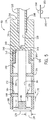
- FIG. 5 illustrates a cross-sectional view of an embodiment of the probe 80.
- the sheath member 108 and the transition member 110 circumferentially surround the light pipe 84 and a waveguide (e.g., fiber optic cabling 128), respectively.
- the fiber optic cabling 128 transmits the light 92 emitted by the optical source 90 to the thermographic phosphor 86 in the light pipe 84. Additionally, as discussed above, the fiber optic cabling 128 receives the light 94 emitted by the thermographic phosphor 86 and transmits the light 94 to the detector 96.
- the light pipe 84 is surrounded with air (e.g., air cladding, air gap) to efficiently transmit light to the thermographic phosphor 86.
- the air around the light pipe 84 facilitates guiding the light 92, 94 through the light pipe 84, thereby improving signal strength.
- the light pipe 84 has an outer diameter 127 that is smaller than a first inner diameter 129 of the sheath member 108.
- the outer diameter 127 may be between approximately 5% and approximately 80% less than the inner diameter 129 of the sheath member 108.
- an outer wall 130 of the light pipe 84 may be positioned radially 102 away from an inner wall 132 of the sheath member 108 by a distance 134, thereby forming a first annulus 138 between the outer wall 130 of the light pipe 84 and the inner wall 132 of the sheath member 108.
- the first annulus 138 maybe filled with air or any other suitable gas to facilitate guiding transmission of the light 92, 94 through the light pipe 84.
- a portion of the sheath member 108 may be disposed within the transition member 110 such that a sheath end face 140 abuts a first inner surface 142 of the transition member 110.
- the transition member 110 may facilitate alignment of an end face 146 of the light pipe 84 and a fiber end face 148 of the fiber optic cabling 128 to allow transmission of the light 92, 94 between the light pipe 84 and the fiber optic cabling 128.
- the end face 146 of the light pipe 84 and the fiber optic end face 148 may be in contact with one another.
- an air gap 150 may separate the end face 146 and the fiber optic end face 148.
- the air gap 150 may facilitate uniform distribution of the light 92, 94 over a surface area of the transition member 110 before the light 92, 94 impinges onto the respective end face 146, 148. This may mitigate damage to the end face 146, 148 that may result from impingement of high-energy light (e.g., short wavelength light).
- thermographic phosphor 86 in the light pipe 84 may include materials such an yttrium aluminum garnet (YAG) crystal, lutetium aluminum garnet (LuAG) crystal, scandium aluminum garnet (ScAG) crystal, yttrium aluminum boron nitrogen garnet (YABNG) crystal, yttrium aluminium boron garnet (YABG) crystal, quartz crystal, sapphire crystal, or any other suitable crystal doped with a thermographic phosphor.
- YAG yttrium aluminum garnet
- LuAG scandium aluminum garnet
- ScAG yttrium aluminum boron nitrogen garnet
- YABG yttrium aluminium boron garnet
- quartz crystal quartz crystal
- sapphire crystal or any other suitable crystal doped with a thermographic phosphor.
- the crystal may be doped with rare earth elements such as neodymium (Nd), chromium (Cr), erbium (Er), ytterbium (Yb), cerium (Ce), dysprosium (Dy), thulium (Tm), or any other suitable thermographic phosphor and combinations thereof.
- rare earth elements such as neodymium (Nd), chromium (Cr), erbium (Er), ytterbium (Yb), cerium (Ce), dysprosium (Dy), thulium (Tm), or any other suitable thermographic phosphor and combinations thereof.
- thermographic phosphor may require a certain light energy for luminescence that is different from another materially different thermographic phosphor. Similarly, each thermographic phosphor may output light energy that is different from the light energy of another materially different thermographic phosphor.
- the amount of energy emitted by the optical source 90 and/or the thermographic phosphor 86 may be high-energy light (e.g., short wavelength light). The intensity of the high-energy light may damage the end face 146, 148, which is where the light 92, 94 first impinges the light pipe 84 and the fiber optic cabling 128, respectively.
- the air gap 150 may uniformly distribute energy from the light 92, 94 over a surface area of the transition member 110, which may decrease the intensity at which the light 92, 94 impinges on the end face 146, 148. Therefore, damage to the light pipe 84 that may result from the energy associated with the light 92, 94 may be reduced compared to probe configurations that do not include the air gap 150. Additionally, the air gap 150 may allow the end faces 146, 148 of the light pipe 84 and the fiber optic cabling 128, respectively, to include angles, bevels, and/or optical lenses, which may mitigate reflection of the light 92, 94 between the light pipe 84 and the fiber optic cabling 128.
- a portion of the fiber optic cabling 128 is enclosed within the tubing 120, which facilitates coupling the probe 80 to the optical source 90 and the detector 96. Additionally, the tubing 120 maybe used to carry cooling air through the temperature sensor 20 to maintain the fiber optic cabling 128 at a temperature that meets the constraints of the mechanical properties of the fiber optic cabling 128.
- the tubing 120 is inserted into a proximal end 154 of the transition member 110 and through at least a portion of a central passage 158 of the transition member 110.
- the tubing 120 may be threaded into the transition member 110. Threading the tubing 120 may facilitate decoupling the tubing 120 from the transition member 110, for example, during maintenance and/or repair of the probe 80.
- the transition member 110 may be inserted into the tubing 120 such that the tubing 120 circumferentially 104 surrounds at least a portion of the proximal end 154 of the transition member 110.
- An adhesive may be used to adhere the tubing 120 to the transition member 110 to reinforce the coupling between the tubing 120 and the transition member 110.
- brazing and crimping could be used to couple the tubing 120 to the transition member 110.
- the light pipe 84 is disposed within the sheath member 108 such that an air cladding (e.g., air gap) formed within the first annulus 138 of the sheath member 108 circumferentially 104 surrounds the light pipe 84. That is, the first outer wall 130 of the light pipe 84 is not in contact with the inner wall 132 of the sheath member 108.
- the probe 80 may include features that facilitate positioning and securing the light pipe 84 within the first annulus 138 such that at least a portion of the light pipe 84 (e.g., greater than approximately 90% of a total surface area of the light pipe 84) is circumferentially 104 surrounded by air (e.g., air cladding).
- the probe 80 includes radial supports 164 positioned at various locations along the longitudinal axis 100 of the probe 80 and extending radially 102 between the light pipe 84 and the sheath member 108.
- the location of the radial supports 164 corresponds to a position of the plurality of holes 116 on the sheath member 108.
- an adhesive e.g., ceramic adhesive
- the adhesive may be injected into each hole of the plurality of holes 116 of the sheath member 108. Once cured, the adhesive binds to the outer wall 130 of the light pipe 84 and sheath sidewalls 168 of the sheath member 108, thereby forming the radial supports 164 and securing the light pipe 84 within the sheath member 108.
- a first dimension 170 of the radial supports 164 may be controlled by a second dimension 172 of the plurality of holes 116. That is, the first dimension 170 of the radial supports 164 may be limited by the second dimension 172 of the respective hole of the plurality of holes 116. In other embodiments, an injection pressure of the adhesive may be used to control the first dimension 170 of the radial supports 164.
- the radial supports 164 may include inserts (e.g., rods) manufactured from refractory materials and sized to fit within the plurality of holes 116.
- the inserts may be inserted into the plurality of holes 116 and adhered to the outer surface 130 of the light pipe 84 and the sheath sidewalls 168 of the sheath member 108 with the adhesive.
- the rods may be cylindrical, rectangular, prismatic, T-shaped, or any suitable geometry.
- each hole of the plurality of holes 116 may be sized and spaced apart such that each of the radial supports 164 may contact between approximately 0.5 % and approximately 10% of a total surface area of the outer surface 130 of the light pipe 84.
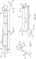
- FIG. 6 illustrates an embodiment of the sheath member 108 having each hole of the plurality of holes 116 spaced apart along both the longitudinal axis 100 and the circumferential axis 104 of the sheath member 108.
- each hole of the plurality of holes 116 is spaced apart a distance 180 (e.g., measured from center to center of each hole) along the longitudinal axis 100 of the sheath member 108.
- each hole of the plurality of holes 116 is circumferentially 104 aligned and spaced apart from an adjacent hole of the plurality of holes 116 by an angle 190.
- the radial supports 164 may contact the light pipe 84 at various points along both the longitudinal axis 100 and the circumferential axis 104 of the light pipe 84 to reinforce and secure the light pipe 84 within the sheath member 108.
- the sheath member 108 may have a first longitudinal dimension 184 and a first outer dimension 186. While the first longitudinal dimension 184 of the sheath member 108 may be any suitable size, in certain embodiments, the first longitudinal dimension 184 of the sheath member 108 maybe between approximately 5% and approximately 250% or more greater than a longitudinal dimension of the light pipe 84 (e.g., the second longitudinal length 210 shown in FIG. 8 ).
- the first outer dimension 186 of the sheath member 108 may be sized to fit into the one or more channels 54 of the temperature manifold 50 (see FIG. 2 ).
- the first outer dimension 186 may be between approximately 0.5% and approximately 5% less than an inner diameter of the one or more channels 54.
- the first outer dimension 186 may be between approximately 1 mm and approximately 5 mm.
- the first outer dimension 186 may be any other suitable size.
- the first longitudinal dimension 184 and the first outer dimension 186 of the sheath member 108 are such that probe 80 has overall dimensions that may be approximately equal to dimensions of conventional thermocouple temperature sensors. As such, the probe 80 may be used to replace thermocouple temperature sensors for fluid temperature measurement applications. Additionally, the air cladding on the light pipe 84 may mitigate other processes that may cause noise or other delays (e.g., scattering).
- the plurality of holes 116 are spaced apart along the longitudinal axis 100 of the sheath member 108. Therefore, in some embodiments, based on the first longitudinal dimension 184 of the sheath member 108, the distance 180 between each hole of the plurality of holes 116 along the longitudinal axis 100 may be between approximately 5% and approximately 50% of the first longitudinal dimension 184. For example, in certain embodiments, the distance 180 may be between approximately 6 millimeters (mm) and approximately 25 mm.
- the radial supports 164 may contact between approximately 0.5 % and approximately 10% of the total surface area of the outer surface 130 of the light pipe 84, and the air cladding on the light pipe 84 may circumferentially 104 surround between approximately 90% and approximately 99% of the light pipe 84. Consequently, the light 92, 94 may be transmitted through the light pipe 84 more efficiently, and signal strength may be improved compared to sensing elements that do not include air cladding.
- a sheath proximal end 192 may include a threaded outer surface 194 that may facilitate coupling the sheath member 108 to the transition member 110 (see FIG. 5 ).
- the sheath proximal end 192 may be inserted into the central passage 158 of the transition member 110 to secure the sheath member 108 to the transition member 110 via a threaded connection.
- the sheath proximal end 192 may have a second outer diameter 196 that may be approximately equal to at least a portion of an inner diameter of the central passage 158 of the transition member 110 (to allow for an interference or friction fit connection). As such, the sheath proximal end 192 may be inserted into a portion of the central passage 158.
- the threaded outer surface 194 of the sheath member 108 may engage with complementary threads within the central passage 158 to secure the sheath member 108 to the transition member 110.
- the second outer diameter 196 may be less than the first outer diameter 186 of the sheath member 108. Therefore, the outer surface of the probe 80 may not have protruding surfaces along the longitudinal axis 100 that may interfere with insertion of the probe 80 into, for example, the respective channel of the plurality of channels 54 of the temperature manifold 50.
- a proximal tip 198 of the sheath member 108 may be tapered.
- the tapered proximal tip 198 may facilitate insertion of the sheath proximal end 192 into the central passage 158 of the transition member 110.
- the first inner surface 142 of the central passage 158 may have a complementary tapered shape that accommodates the tapered proximal tip 198. This arrangement may facilitate alignment between the end face 146 of the light pipe 84 and the fiber end face 148 of the fiber optic cabling 128.
- the sheath member 108 encapsulates the light pipe 84 and the thermographic phosphor 86 (e.g., sensing element) used to measure the temperature of the exhaust gas 24 or any other suitable fluid. Accordingly, the light pipe 84 is dimensioned to fit within the sheath member 108.
- FIG. 8 illustrates an embodiment of the light pipe 84 that may be encapsulated within the sheath member 108.
- the light pipe 84 includes a first end 200 having the end face 146 and a second end 204 that is opposite the first end 200.
- the light pipe 84 includes a first portion 206 and a second portion 208 that form a second longitudinal length 210 of the light pipe 84.
- the first portion 206 of the light pipe 84 extends from the end face 146 to an interface point 209 between the first portion 206 and the second portion 208.
- the second portion 208 may be between approximately 1% and approximately 50% of the second longitudinal length 210 of the light pipe 84.
- the second portion 208 may be any other suitable dimension.
- the first portion 206 may be manufactured from non-doped crystals such as yttrium aluminum garnet (YAG) crystals, sapphire crystals, quartz crystals, or any other suitable crystal that may support the thermographic phosphor 86.
- the second portion 208 may be positioned at the second end 204 and includes the thermographic phosphor 86.
- the thermographic phosphor 86 includes doped crystals such as rare earth- or transition metal-doped YAG, rare earth- or transition metal-doped quartz, or rare earth- or transition metal-doped sapphire crystals. Accordingly, the first portion 206 is the base of the light pipe 84 and the second portion 208 is the dopant.
- first portion 206 and the second portion 208 of the light pipe 84 are monolithic. That is, the non-doped crystal and the doped crystal are bonded together during crystal growth to form a single integrated structure.
- first portion 206 and the second portion 208 are discrete (e.g., non-bonded, unattached) portions that are in contact with one another within the sheath member 108.
- each respective end face of the first portion 206 (e.g., non-doped crystal) and the second portion 208 (e.g., doped crystal) are in contact with one another at the interface point 209.
- the first portion 206 and the second portion 208 are separated from one another such that the portions 206, 208 are not in contact with one another.
- the thermographic phosphor 86 is a powder that maybe disposed on an end face (e.g., end face adjacent to the interface point 209) of the first portion 206.
- the thermographic phosphor powder may be mixed with binders or other suitable materials to consolidate powder particulates and facilitate deposition on the end face of the first portion 206.
- the thermographic phosphor powder may be YABNG:Dy, YABG:Dy, or any other suitable thermographic phosphor.
- the second longitudinal length 210 of the light pipe 84 may be approximately equal to or less than the first longitudinal length 184 of the sheath member 108.
- the second longitudinal length 210 may be such that the first end 200 of the light pipe 84 co-terminates (e.g., is flush) with the proximal end 192 of the sheath member 108.
- the first end 200 of the light pipe 84 is below the proximal end 192 of the sheath member 108.
- the second longitudinal length 210 is greater than the first longitudinal length 184 such that the first end 200 of the light pipe extends beyond the proximal end 192 of the sheath member 108.
- the first end 200 of the light pipe 84 may be inserted into the central passage 158 of the transition member 110.
- FIG. 9 is a cross-sectional view of an embodiment of the transition member 110 that may be used with the probe 80.
- the central passage 158 of the transition member 110 may receive an end of the sheath member 108 (e.g., the proximal end 192) and the tubing 120 to align the end face 146 of the light pipe 84 and the fiber optic end face 148.
- the central passage 158 includes a first section 216, a second section 218, and a third section 220.
- the first section 216 of the central passage 158 longitudinally 100 extends away from the proximal end 154 of the transition member 110 to the second section 218.
- the second section 218 longitudinally 100 extends away from the first section 216 to the third section 220. That is, the second section 218 is positioned between the first and the third sections 216, 220.
- the third section 220 longitudinally 100 extends away from the second section 218 to a transition distal end 226 of the transition member 110.
- the central passage 158 may have a variable diameter to accommodate various components of the probe 80.
- the first section 216 has a first diameter 230 sized to receive the tubing 120
- the second section 218 has a second diameter 232 sized to receive the fiber optic cabling 128,
- the third section 220 has a third diameter 236 sized to receive the proximal end 192 of the sheath member 108 (see FIG. 7 ).
- the central passage 158 may be two separate passages sized to receive a dedicated fiber optic cable for sending the light 92 to the light pipe 84 or a dedicated fiber optic cable for receiving the light 94 emitted by the thermographic phosphor 86.
- the first section 216 includes a threaded inner surface 238 that engages with a complementary threaded outer surface of the tubing 120 to secure the tubing 120 to the transition member 110.
- the threaded connection between the transition member 110 and the tubing 120 may facilitate a secure connection while also allowing decoupling of the tubing 120 from the transition member 110 to replace sensor components (e.g., the tubing 120 and/or the fiber optic cabling 124).
- the first section 216 may not include the threaded inner surface 238. Rather, the inner surface of the first section 216 may be smooth.
- the tubing 120 may be secured within the first section 216 of the transition member 110 via an interference fit (e.g., via ribs on the outer surface of the tubing 120) and/or with an adhesive.
- At least a portion of the first diameter 230 of the first section 216 may gradually decrease.
- the first diameter 230 decreases toward the second section 218 such that the first section 216 tapers toward the second section 218.
- the first diameter 230 of the first section 216 may be constant.
- the second diameter 232 of the second section 216 may be smaller than both the first and third diameters 230, 236 of the first and second sections 216, 220, respectively.
- a transition between the second section 218 and the first and/or third sections 216, 220, respectively, may be gradual (e.g., as in the first diameter 230 and/or the third diameter 236 gradually decreases toward the second section 218) or maybe sudden.
- the second diameter 232 of the second section 216 may decrease toward the third section 220 such that a first step 242 forms within the second section 218.
- the air gap 150 separates the end face 146 of the light pipe 84 and the fiber optic end face 148 of the fiber optic cabling 128 (see FIG. 5 ).
- the first step 242 may block the fiber optic cabling 128 from advancing further down the second section 218 of the central passage 158 toward the third section 220, thereby forming the air gap 150 between the end face 146 of the light pipe 84 and the fiber optic end face 148 of the fiber optic cabling 128.
- the central passage 158 may have a second step 246 (e.g., abutment surface) formed at a transition between the third section 220 and the second section 218.
- the second step 246 blocks the proximal end 192 of the sheath member 108 from advancing into the second section 218.
- the sheath member 108 may be inserted into the third section 220 of the transition member 110.
- the sheath end face 140 of the sheath member 108 abuts the first inner surface 142 associated with the second step 246 of the transition member 110. Therefore, the air gap 150 in the second section 218 is positioned between the first and second steps 242, 246 in the central passage 158 of the transition member 110.
- a second inner surface 250 of the third section 220 may be smooth (e.g., missing ridges or protrusions introduced during manufacturing), and the coupling between the sheath member 108 and the transition member 110 may be via an interference fit connection.
- An adhesive may also be applied to the proximal end 192 of the sheath member 108 and/or the second inner surface 250 of the third section 220 to secure the sheath member 108 to the transition member 110 to reinforce the connection.
- the second inner surface 250 of the third section 220 may be threaded.
- the third section 220 includes a second threaded inner surface 254.
- the second threaded inner surface 254 may facilitate coupling between the transition member 110 and the complementary threaded outer surface 194 at the proximal end 192 of the sheath member 108 (e.g., see FIG. 6 ).
- the threaded connection between the sheath member 108 and the transition member 110 may facilitate a secure connection while also allowing decoupling of the sheath member 108 and the transition member 110.
- the probe 80 may be part of a kit that includes multiple sheath members 108, and/or different thermographic phosphors 86 with different temperature thresholds. An operator of the probe 80 may select the sheath member 108 having a particular one of the thermographic phosphors 86 appropriate (e.g., most suitable) for the temperature measurement application.
- the treaded connection between the sheath member 108 and the transition member 110 may facilitate interchanging between multiple sheath members 108.
- Present embodiments also include techniques that may be used to manufacture the probe 80.
- FIG. 11 illustrates an embodiment of a method 260 to manufacture the probe 80 of the one or more temperature sensors 20 that may be used with the gas turbine system 10 illustrated in FIG. 1 or any other suitable system to measure a temperature of fluids (e.g., the exhaust gas 24).
- FIGS. 12-16 illustrates structures in FIGS. 12-16 , which may correspond to certain of the acts of the method 260.
- the method 260 includes providing a sensor support (e.g., the sheath member 108) having a plurality of holes (e.g., the plurality of holes 116) spaced apart along a length of the sensor support (block 264).
- a sensor support e.g., the sheath member 108
- a plurality of holes e.g., the plurality of holes 116 spaced apart along a length of the sensor support (block 264).
- FIG. 12 is a cross-sectional view of the sheath member 108.
- the sheath member 108 includes a central bore 268 longitudinally 100 extending between a first support end 270 and a second support end 272.
- the first inner diameter 129 of the central bore 268 may be approximately between approximately 1% and 10% larger than the outer diameter 127 of the light pipe 84.
- the plurality of holes 116 are spaced apart and aligned along the longitudinal axis 100 and circumferential axis 104 of the sheath member 108. Each hole of the plurality of holes 116 radially 102 extends through a thickness 274 of a support wall 276 of the sheath member 108 from a support outer surface 278 to the inner surface 132.
- the plurality of holes 116 may be formed via any suitable technique such as drilling, laser cutting, additive manufacturing, or 3D printing. Each hole of the plurality of holes 116 may have an inner diameter 280 of between approximately 0.5 mm and approximately 2.5 mm.
- the method also includes inserting a thermographic light pipe (e.g., the light pipe 84) into the sensor support (block 284) and securing the thermographic light pipe to the sensor support (block 286) to generate a thermographic sensing assembly.
- a thermographic sensing assembly 288 resulting from the acts of blocks 284 and 286.
- the light pipe 84 may be inserted into the central bore 268 through the first support end 270 and pushed toward the second support end 272.
- the second support end 272 is sealed. That is, the central bore 268 of the sheath member 108 is closed at the second support end 272.
- the second support end 272 is open.
- the second end 204 of the light pipe 84 is flush with the second support end 272. However, in other embodiments, the second support end 272 may extend past the second end 204 of the light pipe 84.
- the light pipe 84 is secured to the sheath member 108 with the radial supports 164 to form the thermographic sensing assembly 288.
- an adhesive e.g., a cement adhesive
- the adhesive binds to a portion of the outer wall 130 of the light pipe 84 and to the sidewalls 168 within the plurality of holes 116 of the sheath member 108, thereby securing the light pipe 84 to the sheath member 108.
- rods made of refractory material may be inserted into each hole of the plurality of holes 116 and secured to the outer wall 130 of the light pipe 84 and the sidewalls 168 of the sheath member 108 with the adhesive.
- the radial supports 164 at discrete locations along the longitudinal axis 100 and the circumferential axis 104 of the sheath member 108, the light pipe 84 is secured within the sheath member 108 such that the light pipe 84 has an air cladding about the circumferential axis 104.
- the air cladding results from air within the first annulus 138 between the inner wall 132 of the sheath member 108 and the outer wall 130 of the light pipe 84. In this way, the light pipe 84 may appear to be floating within the sheath member 108.
- the sheath member 108 may be similar to a clamshell.
- the sheath member may include two half portions that when combined (e.g., coupled along the first longitudinal dimension 184) form a sheath member.
- FIG. 14 is a cross-sectional view of a clamshell sheath member 281 having a first half portion 282, a second half portion 283, and a shaped central passage 285 that supports the light pipe 84.
- the first half portion 282 is a separate piece from the second half portion 283.
- the portions 282, 283 may be held together by a hinge positioned along the longitudinal dimension 184 on one side (e.g., outer wall) of the clamshell sheath member 281.
- Each half portion 282, 283 may include a v-groove 287 that extends along a longitudinal length of the clamshell sheath member 281 (e.g., the first longitudinal dimension 184).
- the v-groove 287 of each half portion 282, 283 defines the shaped central passage 285 when the half portions 282, 283 are coupled to one another via abutments surfaces 289. Due, in part, to the v-shaped geometry of the v-groove 287, the shaped central passage 285 may have a square-like geometry.
- the v-groove may include one or more recesses 292 extending along the longitudinal length of one or both half portion 282, 283. Similar to the apexes 291, the one or more recesses 292 may form the air gap 150 such that certain portions of an inner surface the v-groove 287 are not in contact with the light pipe 84. While in the illustrated embodiment, the one or more recesses 292 have v-shape, the one or more recesses 287 may have any other suitable geometric shape.
- the method 260 upon securing the light pipe 84 within the central bore 268 of the sheath member 108 to generate the thermographic sensing assembly 288, the method 260 includes attaching the fiber optic cabling 128 to the thermographic sensing assembly 288 (block 290). This may be accomplished by attaching the fiber optic cabling 128 directly to the thermographic sensing assembly 288, the transition member 110, or a sensor sleeve positioned over the thermographic sensing assembly 288.
- FIG. 15 illustrates an embodiment of the thermographic sensing assembly 288 having the fiber optic end face 148 of the fiber optic cabling 128 attached to the end face 146 of the light pipe 84.
- the end faces 146, 148 are in contact with one another.
- the fiber optic cabling 128 may be attached to the thermographic sensing assembly 288 with fasteners, adhesives, or any other suitable attachment technique.
- a joint 289 maybe positioned over the respective end faces 146, 148 of the light pipe 84 and the fiber optic cabling 128 to attach the fiber optic cabling 128 to the thermographic sensor assembly 288.
- the joint 289 may have an inner diameter sized to fit over both the light pipe 84 and the fiber optic cabling 128. That is, an inner diameter of an end portion of the of the joint 289 may be approximately equal to the outer diameter 127 of the light pipe 84 and an inner diameter of another end portion of the joint 289 may be approximately equal to an outer diameter of the fiber optic cabling 128.
- the transition member 110 may be used to facilitate attachment of the fiber optic cabling 128 to the thermographic sensor assembly 288.
- the fiber optic cabling 128 may be disposed within the transition member 110.
- the transition member 110 may be coupled to the thermographic sensing assembly 288 (e.g., via a threaded or interference fit connection).
- the transition member 110 may also facilitate separating the end faces 146, 148 of the light pipe 84 and the fiber optic cabling 128, respectively, such that the end faces 146, 148 are not in contact with one another.
- the transition member 110 may have features (e.g., the steps 242, 246) that block advancement of the light pipe 84 and the fiber optic cabling 128 through at least a portion of the central passage 158 of the transition member 110. Consequently, the air gap 150 may separate the end faces 146, 148 of the light pipe 84 and the fiber optic cabling 128, respectively.
- the tubing 120 may be attached to the transition member 110 before or after coupling of the thermographic sensor assembly 288 and the transition member 110 to complete assembly of the probe 80.
- thermographic sensor assembly 288 may be inserted into a sleeve that encapsulates the thermographic sensor assembly 288, and the fiber optic cabling 128 may be attached to the thermographic sensor assembly 288 via the sleeve.
- FIG. 16 illustrates a portion of the probe 80 having the thermographic sensor assembly 288 inserted into a sleeve 296 that circumferentially 104 surrounds the sheath member 108 and the light pipe 84 along the longitudinal axis 100.
- the sleeve 296 may be manufactured from refractory materials (e.g., ceramics) suitable for high temperature environments.
- the sleeve 296 includes a first sleeve end 298 and a sleeve inner diameter 300 sized to fit the sheath member 108.
- the sleeve inner diameter 300 may be between approximately 1% and approximately 15% larger than the first outer dimension 186 of the sheath member 108.
- the thermographic sensor assembly 288 may be inserted into the first sleeve end 298.
- a second annulus 302 between the thermographic sensor assembly 288 and the sleeve 296 may be filled with an adhesive 303 (e.g., ceramic adhesive) to secure the thermographic sensor assembly 288 to the sleeve 296.
- the fiber optic cabling 128 maybe inserted into a channel 305 positioned at a second end 304 of the sleeve 296 and coupled to the light pipe 84 of the thermographic sensor assembly 288, for example, with an adhesive.
- the sleeve 296 may be secured onto the transition member 110 in a manner similar to the sheath member 108.
- the sleeve 296 may be secured to the transition member 110 via a threaded connection and/or an interference fit connection that may or may not use adhesives. Therefore, rather than the sheath member 108 being secured to the transition member 110, the sleeve 296 is secured to the transition member 110 to form the probe 80.
- a second sleeve end 304 may have a second sleeve outer diameter 306 that is smaller than the first sleeve outer diameter 296.
- the second sleeve outer diameter 306 may be approximately equal to the third outer diameter 236 of the third section 220 of the central passage 158 in the transition member 110. Accordingly, the second sleeve end 304 may be coupled to the transition member 110 in a manner similar to the sheath member 108. Before or after coupling of the second sleeve end 304 and the transition member 110, the tubing 120 may be attached to the transition member 110 to complete assembly of the probe 80.
- the probe 80 may not include the transition member 110.
- the tube 120 may be coupled to the second sleeve end 304.
- the tube 120 may be secured onto the sleeve 296 with an adhesive and or by crimping or swaging the tube 120 to the second sleeve end 304.
- thermographic phosphor e.g., the probe 80
- a fluid e.g., an exhaust gas
- high temperature environments e.g., in a combustor of a gas turbine engine
- the probe 80 may be manufactured from refractory materials (e.g., ceramic materials) that may tolerate high temperatures generally seen in, for example, gas turbine systems and gasification systems, among others.
- the probe 80 includes the thermographic phosphor 86 on an end of the light pipe 84 that absorbs radiation (e.g., light 92) emitted by a radiation source (e.g., the optical source 90), and in response luminesce (e.g., emit the light 94).
- the luminescence lifetime of the thermographic phosphor 86 is temperature dependent. Therefore, the intensity of the light 94 may be measured over time to determine the temperature of the fluid of interest (e.g., the exhaust gas 24).
- the temperature sensors disclosed herein may replace and/or supplement the use of thermocouples, for example, in temperature environments that may be outside a temperature threshold for thermocouple temperature sensors. Replacing the use of thermocouple temperature sensors for measuring temperatures in high temperature systems such as gas turbine system and gasification systems may decrease the overall costs associated with replacing thermocouples that have been exposed to temperatures above the their temperature limits.
Landscapes
- Physics & Mathematics (AREA)
- General Physics & Mathematics (AREA)
- Chemical & Material Sciences (AREA)
- Engineering & Computer Science (AREA)
- Combustion & Propulsion (AREA)
- Spectroscopy & Molecular Physics (AREA)
- Measuring Temperature Or Quantity Of Heat (AREA)
Claims (12)
- Thermographischer Temperaturfühler (20), umfassend:
eine Sonde (80), die ein Gehäuse (82) umfasst, wobei das Gehäuse eine Hülle (108) umfasst, und wobei die Sonde ferner einen Lichtleiter (84) umfasst, der in der Hülle (108) angeordnet ist, wobei:der Lichtleiter (84) einen thermographischen Leuchtstoff (86) umfasst, der dazu konfiguriert ist, in Reaktion auf Absorbieren von Licht zu phosphoreszieren, wobei die Phosphoreszenz durch den thermographischen Leuchtstoff (86) repräsentativ für eine Temperatur eines Fluids in Kontakt mit der Sonde (80) ist; wobei der Fühler dadurch gekennzeichnet ist, dassdie Hülle (108) eine Vielzahl von Löchern (116) umfasst, die von ihrer äußeren Oberfläche zu ihrer inneren Oberfläche angeordnet sind, wobei die Löcher (116) entlang einer Längsachse (100) und einer Umfangsrichtung (104) der Hülle (108) voneinander beabstandet sind; und wobei der Fühler ferner umfassteine Vielzahl von Trägern (164), die dazu konfiguriert sind, den Lichtleiter (84) an der Hülle (108) zu befestigen, und einen Luftspalt, der zwischen einer äußeren Oberfläche des Lichtleiters und der inneren Oberfläche der Hülle (108) angeordnet ist, wobei der Luftspalt mindestens einen Abschnitt des Lichtleiters (84) in Umfangsrichtung umgibt, wobei jeder Träger (164) der Vielzahl von Trägern innerhalb eines Lochs (116) der Vielzahl von Löchern der Hülle (108) angeordnet ist und sich radial zwischen der äußeren Oberfläche der Hülle (108) und dem Lichtleiter (84) erstreckt. - Thermographischer Temperaturfühler (20) nach Anspruch 1, wobei das Gehäuse (82) ein Übergangselement (110) umfasst, das die Hülle (108) trägt.
- Thermographischer Temperaturfühler (20) nach einem der vorstehenden Ansprüche, wobei die Vielzahl von Trägern (164) ein keramisches Haftmittel umfasst, das dazu konfiguriert ist, an einem Abschnitt einer Außenwand des Lichtleiters (84) und einer Seitenwand, die jedes Loch (116) der Vielzahl der Löcher definiert, zu haften.
- Thermographischer Temperaturfühler (20) nach Anspruch 3, wobei die Vielzahl von Trägern (164) weniger als etwa 10 % des Gesamtoberflächenbereichs des Lichtleiters (84) kontaktiert.
- Thermographischer Temperaturfühler (20) nach einem der vorstehenden Ansprüche, wobei das Übergangselement (110) einen zentralen Durchgang (158) mit einem ersten Bereich (216), einem zweiten Bereich (218) und einem dritten Bereich (220) umfasst, wobei der zweite Bereich (218) zwischen dem ersten Bereich (216) und dem dritten Bereich (220) angeordnet ist, und wobei jeder Bereich des zentralen Durchgangs (158) einen Durchmesser aufweist, der sich von einem anderen Bereich des zentralen Durchgangs (158) unterscheidet.
- Thermographischer Temperaturfühler (20) nach Anspruch 5, wobei ein Abschnitt der Hülle (108) und des Lichtleiters (84) innerhalb des ersten Bereichs (216) angeordnet ist und ein Wellenleiter innerhalb des zweiten (218) und dritten (220) Bereichs des zentralen Durchgangs (158) angeordnet ist, wobei der Wellenleiter dazu konfiguriert ist, das Licht zu dem thermographischen Leuchtstoff (86) zu übertragen.
- Thermographischer Temperaturfühler (20) nach einem der vorstehenden Ansprüche, wobei der Lichtleiter (84) einen Kristall einschließt, der Yttrium-Aluminium-Granat (YAG), Yttrium-Aluminium-Bor-Stickstoff-Granat (YABNG), Yttrium-Aluminium-Bor-Granat (YABG), Lutetium-Aluminium-Granat (LuAG), Scandium-Aluminium-Granat (ScAG), Saphir oder Quarz umfasst.
- Thermografischer Temperaturfühler (20) nach einem der vorstehenden Ansprüche, umfassend:eine optische Quelle (90), die mit der Sonde gekoppelt und dazu konfiguriert ist, Licht (92) an den thermographischen Leuchtstoff (86) zu emittieren, wobei der thermographische Leuchtstoff (86) dazu konfiguriert ist, in Reaktion auf das Absorbieren des Lichts von der optischen Quelle (90) zu phosphoreszieren; undeinen Detektor (96), der mit der Sonde gekoppelt und dazu konfiguriert ist, die Phosphoreszenz durch den thermographischen Leuchtstoff (86) zu detektieren.
- Thermographischer Temperaturfühler (20) nach einem der vorstehenden Ansprüche, wobei die Hülle (108) ein offenes Ende aufweist, so dass der Abschnitt des Lichtleiters (84), der den thermographischen Leuchtstoff (86) umfasst, im Gebrauch dem Fluid ausgesetzt ist, dessen Temperatur erfasst werden soll.
- Verfahren zur Herstellung einer thermographischen Temperatursonde (20), umfassend
Bereitstellen eines Temperaturfühlerträgers, der dazu konfiguriert ist, einen Teil eines Gehäuses (82) der thermographischen Temperatursonde (20) zu bilden, wobei der Temperaturfühlerträger eine zentrale Bohrung (268) umfasst,
Einsetzen eines Lichtleiters (84) in die zentrale Bohrung (268) des Temperaturfühlerträgers, wobei der Lichtleiter (84) einen thermographischen Leuchtstoff (86) umfasst, der dazu konfiguriert ist, in Reaktion auf Absorbieren von Licht zu phosphoreszieren, und wobei die Phosphoreszenz durch den thermographischen Leuchtstoff (86) für eine Temperatur eines Fluids in Kontakt mit der thermographischen Temperatursonde (20) repräsentativ ist; wobei das Verfahren gekennzeichnet ist durch
Bereitstellen einer Vielzahl von Öffnungen in dem Temperaturfühlerträger, wobei jede Öffnung der Vielzahl von Öffnungen von einer angrenzenden Öffnung der Vielzahl von Öffnungen entlang einer Längsachse und einer Umfangsrichtung des Fühlerträgers beabstandet ist;
Befestigen des Lichtleiters (84) an dem Temperaturfühlerträger unter Verwendung von Trägern (164), die sich radial durch die jeweiligen Öffnungen und zwischen dem Lichtleiter (84) und dem Temperaturfühlerträger erstrecken, so dass der Lichtleiter (84) innerhalb des Temperaturfühlerträgers aufgehängt ist. - Verfahren nach Anspruch 10, umfassend das Koppeln des Temperaturfühlerträgers mit einem Rohr, das einen Wellenleiter umfasst, wobei der Wellenleiter dazu konfiguriert ist, Licht zu dem thermographischen Leuchtstoff (86) zu übertragen.
- Verfahren nach Anspruch 10, wobei das Befestigen des Lichtleiters (84) an dem Temperaturfühlerträger das Einspritzen eines keramischen Haftmittels in jede Öffnung der Vielzahl von Öffnungen umfasst, um die Träger (164) zu definieren, wobei das keramische Haftmittel an dem Lichtleiter (84) und dem Temperaturfühlerträger haftet.
Applications Claiming Priority (1)
| Application Number | Priority Date | Filing Date | Title |
|---|---|---|---|
| US15/279,090 US10222274B2 (en) | 2016-09-28 | 2016-09-28 | Thermographic temperature sensor |
Publications (2)
| Publication Number | Publication Date |
|---|---|
| EP3301416A1 EP3301416A1 (de) | 2018-04-04 |
| EP3301416B1 true EP3301416B1 (de) | 2020-09-16 |
Family
ID=59968963
Family Applications (1)
| Application Number | Title | Priority Date | Filing Date |
|---|---|---|---|
| EP17192356.8A Active EP3301416B1 (de) | 2016-09-28 | 2017-09-21 | Thermographischer temperaturfühler |
Country Status (4)
| Country | Link |
|---|---|
| US (1) | US10222274B2 (de) |
| EP (1) | EP3301416B1 (de) |
| JP (1) | JP7053200B2 (de) |
| CN (1) | CN107870042B (de) |
Families Citing this family (10)
| Publication number | Priority date | Publication date | Assignee | Title |
|---|---|---|---|---|
| US10222274B2 (en) * | 2016-09-28 | 2019-03-05 | General Electric Company | Thermographic temperature sensor |
| US10240986B2 (en) * | 2016-09-28 | 2019-03-26 | General Electric Company | Thermographic temperature sensor |
| US10451484B2 (en) * | 2017-01-12 | 2019-10-22 | General Electric Company | Temperature sensor system and method |
| EP3570777B1 (de) | 2017-01-20 | 2024-08-28 | W. L. Gore & Associates, Inc. | Emboliefiltersystem |
| DE102018111167A1 (de) * | 2018-05-09 | 2019-11-14 | Endress + Hauser Wetzer Gmbh + Co. Kg | Messeinsatz mit Schutzrohr |
| CN112888403B (zh) * | 2018-10-17 | 2024-07-30 | W.L.戈尔及同仁股份有限公司 | 带有柔性联接部的栓子过滤器 |
| EP3931537A4 (de) * | 2019-03-01 | 2023-02-22 | Daryl James | Vorrichtung zur messung des fluoreszenzzeitverfalls und verfahren zu ihrer herstellung |
| CN111811681A (zh) * | 2020-02-27 | 2020-10-23 | 重庆大学 | 吸气式光纤光栅总温探针及其测量系统 |
| WO2021181494A1 (ja) * | 2020-03-10 | 2021-09-16 | オリンパス株式会社 | 医療用マニピュレータ |
| WO2021181493A1 (ja) | 2020-03-10 | 2021-09-16 | オリンパス株式会社 | 医療用マニピュレータ |
Family Cites Families (23)
| Publication number | Priority date | Publication date | Assignee | Title |
|---|---|---|---|---|
| US4075493A (en) * | 1976-12-16 | 1978-02-21 | Ronald Alves | Optical temperature measurement technique utilizing phosphors |
| CA1108428A (en) * | 1976-12-16 | 1981-09-08 | Kenneth A. Wickersheim | Optical temperature measurement technique utilizing phosphors |
| JPH0244186Y2 (de) * | 1980-11-07 | 1990-11-22 | ||
| SE448186B (sv) | 1983-04-12 | 1987-01-26 | Asea Ab | Fiberoptisk givare |
| US5110216A (en) * | 1989-03-30 | 1992-05-05 | Luxtron Corporation | Fiberoptic techniques for measuring the magnitude of local microwave fields and power |
| JPH04113040U (ja) * | 1991-03-15 | 1992-10-01 | 株式会社高岳製作所 | 光フアイバ温度センサ |
| WO2006020770A2 (en) * | 2004-08-11 | 2006-02-23 | University Of South Florida | Thermally compensated fluorescence decay rate temperature sensor and method of use |
| DE502005001625D1 (de) | 2005-01-14 | 2007-11-15 | Siemens Ag | Beschichtetes Bauteil und Verfahren zur Herstellung |
| US20070171958A1 (en) * | 2006-01-23 | 2007-07-26 | Anh Hoang | Electrical device measurement probes |
| US7789556B2 (en) * | 2006-11-16 | 2010-09-07 | University Of South Florida | Thermally compensated dual-probe fluorescence decay rate temperature sensor and method of use |
| JP5001119B2 (ja) * | 2007-11-22 | 2012-08-15 | アズビル株式会社 | 温度センサプローブ、及びその製造方法 |
| JP5064183B2 (ja) * | 2007-11-22 | 2012-10-31 | アズビル株式会社 | 温度センサプローブの製造方法 |
| JP5299812B2 (ja) * | 2008-03-31 | 2013-09-25 | アズビル株式会社 | 蛍光温度センサ |
| WO2011073789A2 (en) * | 2009-12-18 | 2011-06-23 | Schlumberger Technology B.V. | Immersion probe using ultraviolet and infrared radiation for multi-phase flow analysis |
| JP2013158445A (ja) * | 2012-02-03 | 2013-08-19 | Hoya Corp | 走査型プローブ、走査型観察システム、一体型内視鏡、及び一体型内視鏡システム |
| US8969808B2 (en) * | 2012-06-19 | 2015-03-03 | Amphenol Thermometrics, Inc. | Non-dispersive infrared sensor with a reflective diffuser |
| US9599518B2 (en) | 2013-01-29 | 2017-03-21 | Nicholas I. Djeu | Fiber optic temperature sensor utilizing a phosphor microsphere |
| US9696217B2 (en) * | 2013-10-30 | 2017-07-04 | United Technologies Corporation | Phosphor thermometer with two waveguides |
| CN203688072U (zh) * | 2014-02-24 | 2014-07-02 | 上海协同物理研究所 | 一种焦化炉立火道红外测温装置 |
| JP6296958B2 (ja) * | 2014-10-15 | 2018-03-20 | アズビル株式会社 | 蛍光温度センサ |
| CN105841824B (zh) * | 2016-03-23 | 2019-01-29 | 东南大学 | 一种非接触便携式温度实时测量装置 |
| US10240986B2 (en) | 2016-09-28 | 2019-03-26 | General Electric Company | Thermographic temperature sensor |
| US10222274B2 (en) * | 2016-09-28 | 2019-03-05 | General Electric Company | Thermographic temperature sensor |
-
2016
- 2016-09-28 US US15/279,090 patent/US10222274B2/en active Active
-
2017
- 2017-09-14 JP JP2017176273A patent/JP7053200B2/ja not_active Expired - Fee Related
- 2017-09-21 EP EP17192356.8A patent/EP3301416B1/de active Active
- 2017-09-28 CN CN201710902912.1A patent/CN107870042B/zh not_active Expired - Fee Related
Non-Patent Citations (1)
| Title |
|---|
| None * |
Also Published As
| Publication number | Publication date |
|---|---|
| EP3301416A1 (de) | 2018-04-04 |
| JP7053200B2 (ja) | 2022-04-12 |
| JP2018072326A (ja) | 2018-05-10 |
| US20180087975A1 (en) | 2018-03-29 |
| US10222274B2 (en) | 2019-03-05 |
| CN107870042B (zh) | 2022-07-26 |
| CN107870042A (zh) | 2018-04-03 |
Similar Documents
| Publication | Publication Date | Title |
|---|---|---|
| US10222274B2 (en) | Thermographic temperature sensor | |
| EP3301421B1 (de) | Thermographischer temperaturfühler | |
| CN103511005B (zh) | 涡轮机械监测系统和方法 | |
| US8280202B2 (en) | Fiber-optic dynamic sensing modules and methods | |
| US9696217B2 (en) | Phosphor thermometer with two waveguides | |
| US8009939B2 (en) | Fiberoptic clearance detection system and method | |
| US5148667A (en) | Gas turbine flame diagnostic monitor | |
| US20110231110A1 (en) | Fiber Optic Sensor System for Detecting Surface Wear | |
| EP2028421A1 (de) | Überwachung der Flammenanwesenheit und der Flammentemperatur | |
| US9518894B2 (en) | Device for measuring vibration amplitudes of the blade tips in a turbomachine | |
| KR20100048920A (ko) | 블레이드 팁 간극 검사 시스템 및 장치 | |
| US20150117493A1 (en) | Phosphor Thermometry Fiber Sensor | |
| Nau et al. | Wall temperature measurements in a full-scale gas turbine combustor test rig with fiber coupled phosphor thermometry | |
| KR102026827B1 (ko) | 가스 터빈 및 그 모니터링 시스템 | |
| EP2221593A2 (de) | Integrierte Vorrichtung zur statischen Druckmessung | |
| US20140269817A1 (en) | Phosphor Thermometry Fiber Sensor | |
| CN102017009A (zh) | 自动远程测量反应堆内部间隙的装置和方法 | |
| KR102038555B1 (ko) | 가스터빈 및 가스터빈의 제어방법 | |
| EP2902706A1 (de) | Verfahren zur Überwachung einer Brennkammer | |
| Sollazzo et al. | Application of a production line phosphorescence sensor coating system on a jet engine for surface temperature detection | |
| US20210255044A1 (en) | Protective sleeve for a component of a turbine engine and method of installing the same | |
| EP3535556A2 (de) | Verbrennungsdrucksensor und dessen anordnung in einer motorkomponente eines verbrennungsmotors | |
| Stuttaford et al. | Combustion noise measurement system for low emissions combustor performance optimization and health monitoring | |
| US20180195910A1 (en) | Temperature sensor system and method | |
| Berexa et al. | Measurement of Internal Temperatures in Engine-Scale Gas Turbine Blade with Fiber Optic Sensors |
Legal Events
| Date | Code | Title | Description |
|---|---|---|---|
| PUAI | Public reference made under article 153(3) epc to a published international application that has entered the european phase |
Free format text: ORIGINAL CODE: 0009012 |
|
| STAA | Information on the status of an ep patent application or granted ep patent |
Free format text: STATUS: THE APPLICATION HAS BEEN PUBLISHED |
|
| AK | Designated contracting states |
Kind code of ref document: A1 Designated state(s): AL AT BE BG CH CY CZ DE DK EE ES FI FR GB GR HR HU IE IS IT LI LT LU LV MC MK MT NL NO PL PT RO RS SE SI SK SM TR |
|
| AX | Request for extension of the european patent |
Extension state: BA ME |
|
| STAA | Information on the status of an ep patent application or granted ep patent |
Free format text: STATUS: REQUEST FOR EXAMINATION WAS MADE |
|
| 17P | Request for examination filed |
Effective date: 20181004 |
|
| RBV | Designated contracting states (corrected) |
Designated state(s): AL AT BE BG CH CY CZ DE DK EE ES FI FR GB GR HR HU IE IS IT LI LT LU LV MC MK MT NL NO PL PT RO RS SE SI SK SM TR |
|
| STAA | Information on the status of an ep patent application or granted ep patent |
Free format text: STATUS: EXAMINATION IS IN PROGRESS |
|
| 17Q | First examination report despatched |
Effective date: 20190425 |
|
| GRAP | Despatch of communication of intention to grant a patent |
Free format text: ORIGINAL CODE: EPIDOSNIGR1 |
|
| STAA | Information on the status of an ep patent application or granted ep patent |
Free format text: STATUS: GRANT OF PATENT IS INTENDED |
|
| INTG | Intention to grant announced |
Effective date: 20200414 |
|
| GRAS | Grant fee paid |
Free format text: ORIGINAL CODE: EPIDOSNIGR3 |
|
| GRAA | (expected) grant |
Free format text: ORIGINAL CODE: 0009210 |
|
| STAA | Information on the status of an ep patent application or granted ep patent |
Free format text: STATUS: THE PATENT HAS BEEN GRANTED |
|
| AK | Designated contracting states |
Kind code of ref document: B1 Designated state(s): AL AT BE BG CH CY CZ DE DK EE ES FI FR GB GR HR HU IE IS IT LI LT LU LV MC MK MT NL NO PL PT RO RS SE SI SK SM TR |
|
| REG | Reference to a national code |
Ref country code: GB Ref legal event code: FG4D |
|
| REG | Reference to a national code |
Ref country code: CH Ref legal event code: EP |
|
| REG | Reference to a national code |
Ref country code: DE Ref legal event code: R096 Ref document number: 602017023643 Country of ref document: DE |
|
| REG | Reference to a national code |
Ref country code: IE Ref legal event code: FG4D |
|
| REG | Reference to a national code |
Ref country code: AT Ref legal event code: REF Ref document number: 1314580 Country of ref document: AT Kind code of ref document: T Effective date: 20201015 |
|
| PG25 | Lapsed in a contracting state [announced via postgrant information from national office to epo] |
Ref country code: HR Free format text: LAPSE BECAUSE OF FAILURE TO SUBMIT A TRANSLATION OF THE DESCRIPTION OR TO PAY THE FEE WITHIN THE PRESCRIBED TIME-LIMIT Effective date: 20200916 Ref country code: SE Free format text: LAPSE BECAUSE OF FAILURE TO SUBMIT A TRANSLATION OF THE DESCRIPTION OR TO PAY THE FEE WITHIN THE PRESCRIBED TIME-LIMIT Effective date: 20200916 Ref country code: BG Free format text: LAPSE BECAUSE OF FAILURE TO SUBMIT A TRANSLATION OF THE DESCRIPTION OR TO PAY THE FEE WITHIN THE PRESCRIBED TIME-LIMIT Effective date: 20201216 Ref country code: FI Free format text: LAPSE BECAUSE OF FAILURE TO SUBMIT A TRANSLATION OF THE DESCRIPTION OR TO PAY THE FEE WITHIN THE PRESCRIBED TIME-LIMIT Effective date: 20200916 Ref country code: GR Free format text: LAPSE BECAUSE OF FAILURE TO SUBMIT A TRANSLATION OF THE DESCRIPTION OR TO PAY THE FEE WITHIN THE PRESCRIBED TIME-LIMIT Effective date: 20201217 Ref country code: NO Free format text: LAPSE BECAUSE OF FAILURE TO SUBMIT A TRANSLATION OF THE DESCRIPTION OR TO PAY THE FEE WITHIN THE PRESCRIBED TIME-LIMIT Effective date: 20201216 |
|
| REG | Reference to a national code |
Ref country code: AT Ref legal event code: MK05 Ref document number: 1314580 Country of ref document: AT Kind code of ref document: T Effective date: 20200916 |
|
| REG | Reference to a national code |
Ref country code: NL Ref legal event code: MP Effective date: 20200916 |
|
| PG25 | Lapsed in a contracting state [announced via postgrant information from national office to epo] |
Ref country code: LV Free format text: LAPSE BECAUSE OF FAILURE TO SUBMIT A TRANSLATION OF THE DESCRIPTION OR TO PAY THE FEE WITHIN THE PRESCRIBED TIME-LIMIT Effective date: 20200916 Ref country code: RS Free format text: LAPSE BECAUSE OF FAILURE TO SUBMIT A TRANSLATION OF THE DESCRIPTION OR TO PAY THE FEE WITHIN THE PRESCRIBED TIME-LIMIT Effective date: 20200916 |
|
| REG | Reference to a national code |
Ref country code: LT Ref legal event code: MG4D |
|
| PG25 | Lapsed in a contracting state [announced via postgrant information from national office to epo] |
Ref country code: CZ Free format text: LAPSE BECAUSE OF FAILURE TO SUBMIT A TRANSLATION OF THE DESCRIPTION OR TO PAY THE FEE WITHIN THE PRESCRIBED TIME-LIMIT Effective date: 20200916 Ref country code: PT Free format text: LAPSE BECAUSE OF FAILURE TO SUBMIT A TRANSLATION OF THE DESCRIPTION OR TO PAY THE FEE WITHIN THE PRESCRIBED TIME-LIMIT Effective date: 20210118 Ref country code: RO Free format text: LAPSE BECAUSE OF FAILURE TO SUBMIT A TRANSLATION OF THE DESCRIPTION OR TO PAY THE FEE WITHIN THE PRESCRIBED TIME-LIMIT Effective date: 20200916 Ref country code: LT Free format text: LAPSE BECAUSE OF FAILURE TO SUBMIT A TRANSLATION OF THE DESCRIPTION OR TO PAY THE FEE WITHIN THE PRESCRIBED TIME-LIMIT Effective date: 20200916 Ref country code: SM Free format text: LAPSE BECAUSE OF FAILURE TO SUBMIT A TRANSLATION OF THE DESCRIPTION OR TO PAY THE FEE WITHIN THE PRESCRIBED TIME-LIMIT Effective date: 20200916 Ref country code: EE Free format text: LAPSE BECAUSE OF FAILURE TO SUBMIT A TRANSLATION OF THE DESCRIPTION OR TO PAY THE FEE WITHIN THE PRESCRIBED TIME-LIMIT Effective date: 20200916 |
|
| REG | Reference to a national code |
Ref country code: CH Ref legal event code: PL |
|
| PG25 | Lapsed in a contracting state [announced via postgrant information from national office to epo] |
Ref country code: ES Free format text: LAPSE BECAUSE OF FAILURE TO SUBMIT A TRANSLATION OF THE DESCRIPTION OR TO PAY THE FEE WITHIN THE PRESCRIBED TIME-LIMIT Effective date: 20200916 Ref country code: AT Free format text: LAPSE BECAUSE OF FAILURE TO SUBMIT A TRANSLATION OF THE DESCRIPTION OR TO PAY THE FEE WITHIN THE PRESCRIBED TIME-LIMIT Effective date: 20200916 Ref country code: AL Free format text: LAPSE BECAUSE OF FAILURE TO SUBMIT A TRANSLATION OF THE DESCRIPTION OR TO PAY THE FEE WITHIN THE PRESCRIBED TIME-LIMIT Effective date: 20200916 Ref country code: PL Free format text: LAPSE BECAUSE OF FAILURE TO SUBMIT A TRANSLATION OF THE DESCRIPTION OR TO PAY THE FEE WITHIN THE PRESCRIBED TIME-LIMIT Effective date: 20200916 Ref country code: IS Free format text: LAPSE BECAUSE OF FAILURE TO SUBMIT A TRANSLATION OF THE DESCRIPTION OR TO PAY THE FEE WITHIN THE PRESCRIBED TIME-LIMIT Effective date: 20210116 |
|
| REG | Reference to a national code |
Ref country code: DE Ref legal event code: R097 Ref document number: 602017023643 Country of ref document: DE |
|
| REG | Reference to a national code |
Ref country code: BE Ref legal event code: MM Effective date: 20200930 |
|
| PG25 | Lapsed in a contracting state [announced via postgrant information from national office to epo] |
Ref country code: LU Free format text: LAPSE BECAUSE OF NON-PAYMENT OF DUE FEES Effective date: 20200921 Ref country code: MC Free format text: LAPSE BECAUSE OF FAILURE TO SUBMIT A TRANSLATION OF THE DESCRIPTION OR TO PAY THE FEE WITHIN THE PRESCRIBED TIME-LIMIT Effective date: 20200916 Ref country code: SK Free format text: LAPSE BECAUSE OF FAILURE TO SUBMIT A TRANSLATION OF THE DESCRIPTION OR TO PAY THE FEE WITHIN THE PRESCRIBED TIME-LIMIT Effective date: 20200916 |
|
| PLBE | No opposition filed within time limit |
Free format text: ORIGINAL CODE: 0009261 |
|
| STAA | Information on the status of an ep patent application or granted ep patent |
Free format text: STATUS: NO OPPOSITION FILED WITHIN TIME LIMIT |
|
| 26N | No opposition filed |
Effective date: 20210617 |
|
| PG25 | Lapsed in a contracting state [announced via postgrant information from national office to epo] |
Ref country code: BE Free format text: LAPSE BECAUSE OF NON-PAYMENT OF DUE FEES Effective date: 20200930 Ref country code: CH Free format text: LAPSE BECAUSE OF NON-PAYMENT OF DUE FEES Effective date: 20200930 Ref country code: SI Free format text: LAPSE BECAUSE OF FAILURE TO SUBMIT A TRANSLATION OF THE DESCRIPTION OR TO PAY THE FEE WITHIN THE PRESCRIBED TIME-LIMIT Effective date: 20200916 Ref country code: IE Free format text: LAPSE BECAUSE OF NON-PAYMENT OF DUE FEES Effective date: 20200921 Ref country code: DK Free format text: LAPSE BECAUSE OF FAILURE TO SUBMIT A TRANSLATION OF THE DESCRIPTION OR TO PAY THE FEE WITHIN THE PRESCRIBED TIME-LIMIT Effective date: 20200916 Ref country code: LI Free format text: LAPSE BECAUSE OF NON-PAYMENT OF DUE FEES Effective date: 20200930 |
|
| PG25 | Lapsed in a contracting state [announced via postgrant information from national office to epo] |
Ref country code: FR Free format text: LAPSE BECAUSE OF NON-PAYMENT OF DUE FEES Effective date: 20201116 |
|
| PG25 | Lapsed in a contracting state [announced via postgrant information from national office to epo] |
Ref country code: TR Free format text: LAPSE BECAUSE OF FAILURE TO SUBMIT A TRANSLATION OF THE DESCRIPTION OR TO PAY THE FEE WITHIN THE PRESCRIBED TIME-LIMIT Effective date: 20200916 Ref country code: MT Free format text: LAPSE BECAUSE OF FAILURE TO SUBMIT A TRANSLATION OF THE DESCRIPTION OR TO PAY THE FEE WITHIN THE PRESCRIBED TIME-LIMIT Effective date: 20200916 Ref country code: CY Free format text: LAPSE BECAUSE OF FAILURE TO SUBMIT A TRANSLATION OF THE DESCRIPTION OR TO PAY THE FEE WITHIN THE PRESCRIBED TIME-LIMIT Effective date: 20200916 |
|
| PG25 | Lapsed in a contracting state [announced via postgrant information from national office to epo] |
Ref country code: MK Free format text: LAPSE BECAUSE OF FAILURE TO SUBMIT A TRANSLATION OF THE DESCRIPTION OR TO PAY THE FEE WITHIN THE PRESCRIBED TIME-LIMIT Effective date: 20200916 |
|
| PG25 | Lapsed in a contracting state [announced via postgrant information from national office to epo] |
Ref country code: NL Free format text: LAPSE BECAUSE OF NON-PAYMENT OF DUE FEES Effective date: 20200923 |
|
| PGFP | Annual fee paid to national office [announced via postgrant information from national office to epo] |
Ref country code: IT Payment date: 20230822 Year of fee payment: 7 Ref country code: GB Payment date: 20230823 Year of fee payment: 7 |
|
| REG | Reference to a national code |
Ref country code: DE Ref legal event code: R081 Ref document number: 602017023643 Country of ref document: DE Owner name: GENERAL ELECTRIC TECHNOLOGY GMBH, CH Free format text: FORMER OWNER: GENERAL ELECTRIC COMPANY, SCHENECTADY, NY, US |
|
| PGFP | Annual fee paid to national office [announced via postgrant information from national office to epo] |
Ref country code: DE Payment date: 20230822 Year of fee payment: 7 |
|
| REG | Reference to a national code |
Ref country code: GB Ref legal event code: 732E Free format text: REGISTERED BETWEEN 20240222 AND 20240228 |
|
| REG | Reference to a national code |
Ref country code: DE Ref legal event code: R119 Ref document number: 602017023643 Country of ref document: DE |
|
| GBPC | Gb: european patent ceased through non-payment of renewal fee |
Effective date: 20240921 |
|
| PG25 | Lapsed in a contracting state [announced via postgrant information from national office to epo] |
Ref country code: DE Free format text: LAPSE BECAUSE OF NON-PAYMENT OF DUE FEES Effective date: 20250401 |
|
| PG25 | Lapsed in a contracting state [announced via postgrant information from national office to epo] |
Ref country code: GB Free format text: LAPSE BECAUSE OF NON-PAYMENT OF DUE FEES Effective date: 20240921 |
|
| PG25 | Lapsed in a contracting state [announced via postgrant information from national office to epo] |
Ref country code: IT Free format text: LAPSE BECAUSE OF NON-PAYMENT OF DUE FEES Effective date: 20240921 |