EP3301398B1 - Gyroscope mems ayant une stabilité élevée par rapport aux variations de température et d'humidité - Google Patents
Gyroscope mems ayant une stabilité élevée par rapport aux variations de température et d'humidité Download PDFInfo
- Publication number
- EP3301398B1 EP3301398B1 EP17162662.5A EP17162662A EP3301398B1 EP 3301398 B1 EP3301398 B1 EP 3301398B1 EP 17162662 A EP17162662 A EP 17162662A EP 3301398 B1 EP3301398 B1 EP 3301398B1
- Authority
- EP
- European Patent Office
- Prior art keywords
- signal
- stage
- phase
- mobile mass
- sensing
- Prior art date
- Legal status (The legal status is an assumption and is not a legal conclusion. Google has not performed a legal analysis and makes no representation as to the accuracy of the status listed.)
- Active
Links
- 238000001914 filtration Methods 0.000 claims description 10
- 238000006073 displacement reaction Methods 0.000 claims description 9
- 238000012545 processing Methods 0.000 claims description 6
- 230000010349 pulsation Effects 0.000 claims description 5
- 230000010363 phase shift Effects 0.000 claims description 3
- 239000003990 capacitor Substances 0.000 description 13
- 230000010355 oscillation Effects 0.000 description 9
- 238000000034 method Methods 0.000 description 5
- 230000008878 coupling Effects 0.000 description 4
- 238000010168 coupling process Methods 0.000 description 4
- 238000005859 coupling reaction Methods 0.000 description 4
- 238000010586 diagram Methods 0.000 description 4
- 230000000284 resting effect Effects 0.000 description 4
- 239000000463 material Substances 0.000 description 3
- 230000008569 process Effects 0.000 description 3
- 239000004065 semiconductor Substances 0.000 description 3
- 238000012546 transfer Methods 0.000 description 3
- 230000001427 coherent effect Effects 0.000 description 2
- 230000000694 effects Effects 0.000 description 2
- 230000000737 periodic effect Effects 0.000 description 2
- 230000035945 sensitivity Effects 0.000 description 2
- 238000005476 soldering Methods 0.000 description 2
- 230000001133 acceleration Effects 0.000 description 1
- 230000008859 change Effects 0.000 description 1
- 238000001514 detection method Methods 0.000 description 1
- 238000004519 manufacturing process Methods 0.000 description 1
- 238000012986 modification Methods 0.000 description 1
- 230000004048 modification Effects 0.000 description 1
- 238000011084 recovery Methods 0.000 description 1
- 238000000926 separation method Methods 0.000 description 1
- 229910052710 silicon Inorganic materials 0.000 description 1
- 239000010703 silicon Substances 0.000 description 1
Images


Classifications
-
- G—PHYSICS
- G01—MEASURING; TESTING
- G01C—MEASURING DISTANCES, LEVELS OR BEARINGS; SURVEYING; NAVIGATION; GYROSCOPIC INSTRUMENTS; PHOTOGRAMMETRY OR VIDEOGRAMMETRY
- G01C19/00—Gyroscopes; Turn-sensitive devices using vibrating masses; Turn-sensitive devices without moving masses; Measuring angular rate using gyroscopic effects
- G01C19/56—Turn-sensitive devices using vibrating masses, e.g. vibratory angular rate sensors based on Coriolis forces
- G01C19/5719—Turn-sensitive devices using vibrating masses, e.g. vibratory angular rate sensors based on Coriolis forces using planar vibrating masses driven in a translation vibration along an axis
- G01C19/5733—Structural details or topology
- G01C19/574—Structural details or topology the devices having two sensing masses in anti-phase motion
-
- G—PHYSICS
- G01—MEASURING; TESTING
- G01C—MEASURING DISTANCES, LEVELS OR BEARINGS; SURVEYING; NAVIGATION; GYROSCOPIC INSTRUMENTS; PHOTOGRAMMETRY OR VIDEOGRAMMETRY
- G01C19/00—Gyroscopes; Turn-sensitive devices using vibrating masses; Turn-sensitive devices without moving masses; Measuring angular rate using gyroscopic effects
- G01C19/56—Turn-sensitive devices using vibrating masses, e.g. vibratory angular rate sensors based on Coriolis forces
- G01C19/5719—Turn-sensitive devices using vibrating masses, e.g. vibratory angular rate sensors based on Coriolis forces using planar vibrating masses driven in a translation vibration along an axis
- G01C19/5726—Signal processing
-
- G—PHYSICS
- G01—MEASURING; TESTING
- G01C—MEASURING DISTANCES, LEVELS OR BEARINGS; SURVEYING; NAVIGATION; GYROSCOPIC INSTRUMENTS; PHOTOGRAMMETRY OR VIDEOGRAMMETRY
- G01C19/00—Gyroscopes; Turn-sensitive devices using vibrating masses; Turn-sensitive devices without moving masses; Measuring angular rate using gyroscopic effects
- G01C19/56—Turn-sensitive devices using vibrating masses, e.g. vibratory angular rate sensors based on Coriolis forces
- G01C19/5719—Turn-sensitive devices using vibrating masses, e.g. vibratory angular rate sensors based on Coriolis forces using planar vibrating masses driven in a translation vibration along an axis
- G01C19/5733—Structural details or topology
- G01C19/5755—Structural details or topology the devices having a single sensing mass
Definitions
- the present invention relates to a MEMS gyroscope having a high stability with respect to undesirable phenomena such as, for example, variations of temperature and/or humidity.
- MEMS gyroscopes are today available, which are sensors of angular velocity capable of detecting an external stimulus due to the Coriolis force.
- the Coriolis force is an inertial force that acts on a mobile mass that moves with respect to a rotating reference frame, this force being proportional to the velocity of the mobile mass and to the angular velocity of the reference frame.
- a MEMS gyroscope 1 is formed by a first die 2 of semiconductor material (typically, silicon), which forms a frame 4, mechanically coupled are to which a first mobile mass 6 and a second mobile mass 8, which are also of semiconductor material.
- semiconductor material typically, silicon
- the first and second mobile masses 6, 8 are mechanically coupled to the frame 4 by a first system of springs 10 and a second system of springs 12, respectively, these systems of springs being formed, for example, by suspended and flexible portions of semiconductor material (for example, with the form of beams), set between the frame 4 and the respective mobile mass.
- the first and second systems of springs 10, 12 are designed to enable the first and second mobile masses 6, 8 to move in a direction parallel to the axis x, also referred to as driving direction.
- the first and second mobile masses 6, 8 are mechanically coupled together through a coupling system 14, which is, for example, considered equivalent to a corresponding spring that operates parallel to the axis x.
- the MEMS gyroscope 1 further comprises a system of driving electrodes 16, which includes a first set of driving electrodes 17a and a second set of driving electrodes 17b, and a system of sensing electrodes 18, which includes a first set of sensing electrodes 19a and a second set of sensing electrodes 19b.
- the first set of driving electrodes 17a comprises corresponding electrodes (which are not shown in detail), which are fixed with respect to the frame 4 and have shapes and arrangements such as to cause, when subjected to corresponding voltages, an oscillation of the first mobile mass 6, parallel to the axis x.
- the first mobile mass 6 is thus made to oscillate by electrostatic forces that are set up between the first mobile mass 6 and the first set of driving electrodes 17a.
- the first set of driving electrodes 17a may comprise a first subset of electrodes and a second subset of electrodes (not shown) such that, when they are subjected to mutually opposite a.c. voltages, the first mobile mass 6 oscillates parallel to the axis x.
- the second set of driving electrodes 17b comprises corresponding electrodes (not shown in detail), which are fixed with respect to the frame 4 and have shapes and arrangements such as to cause, when subjected to corresponding voltages, an oscillation of the second mobile mass 8 parallel to the axis x.
- the second mobile mass 8 is thus made to oscillate by electrostatic forces that are set up between the second mobile mass 8 and the second set of driving electrodes 17b.
- the second set of driving electrodes 17b may comprise a respective first subset of electrodes (not shown) and a respective second subset of electrodes (not shown), these first and second subsets of electrodes being such that, when they are subjected to mutually opposite a.c. voltages, the second mobile mass 8 oscillates parallel to the axis x.
- the first set of sensing electrodes 19a comprises corresponding electrodes (not shown in detail), which are fixed with respect to the frame 4 and form a sort of plate, which defines, together with the first mobile mass 6, a first variable capacitor, the capacitance of which is a function of the position of the first mobile mass 6.
- the second set of sensing electrodes 19b comprises corresponding electrodes (not shown in detail), which are fixed with respect to the frame 4 and form a sort of further plate, which defines, together with the second mobile mass 8, a second variable capacitor, the capacitance of which is a function of the position of the second mobile mass 8.
- the MEMS gyroscope 1 further comprises an external sensing circuitry 20, which is formed, for example, in a second die 22, fixed with respect to the first die 2.
- the MEMS gyroscope 1 comprises an external driving circuitry 24, which is also formed in the second die 22.
- the external sensing circuitry 20 is electrically connected to the first and second sets of sensing electrodes 19a, 19b and generates a first sensing signal, which is a function of the capacitance of the first and second variable capacitors and thus indicates the positions of the first and second mobile masses 6, 8.
- the external driving circuitry 24 is electrically coupled to the external sensing circuitry 20 for receiving the first sensing signal.
- the external driving circuitry 24 is electrically coupled to the system of driving electrodes 16 and thus to the first and second sets of driving electrodes 17a, 17b.
- the external driving circuitry 24 supplies to the first and second sets of driving electrodes 17a, 17b the aforementioned voltages that enable the first and second mobile masses 6, 8 to be kept in oscillation. More in particular, the voltages generated by the driving circuitry 24 are such that the first and second mobile masses 6, 8 oscillate with a same frequency f d , but with opposite phases.
- the frequency f d is equal, to a first approximation, to the frequency of mechanical resonance of the mechanical system including the first and second mobile masses 6, 8, the first and second systems of springs 12 and the coupling system 14, referred to in what follows as the "oscillating system".
- a mode of oscillation of the oscillating system is excited, this mode being the one in which the first and second mobile masses 6, 8 oscillate in phase opposition parallel to the axis x, i.e., with velocities (and positions) phase-shifted by 180° and thus with opposite directions.
- the external driving circuitry 24 generates the aforementioned voltages as a function of the first sensing signal, as described in what follows.
- the external driving circuitry 24 may generate, for example, a first driving voltage V d1 and a second driving voltage V d2 , which are of an a.c. type and in phase opposition.
- the first driving voltage V d1 is supplied, for example, to the first subset of electrodes of the first set of driving electrodes 17a and to the first subset of electrodes of the second set of driving electrodes 17b
- the second driving voltage V d2 is supplied, for example, to the second subset of electrodes of the first set of driving electrodes 17a and to the second subset of electrodes of the second set of driving electrodes 17b.
- the first and second driving voltages V d1 , V d2 have a frequency equal to the aforementioned frequency f d , but have opposite phases.
- the MEMS gyroscope 1 further comprises a first conductive plate 28 and a second conductive plate 30, which are set underneath (in the direction of the axis z) of the first and second mobile masses 6, 8, respectively.
- first conductive plate 28 and second conductive plate 30 are set underneath (in the direction of the axis z) of the first and second mobile masses 6, 8, respectively.
- the arrangement of the blocks that represent the first and second conductive plates 28, 30 does not have any geometrical implication.
- the first conductive plate 28 is fixed to the frame 4 and is aligned to the first mobile mass 6 parallel to the axis z. Furthermore, the first mobile mass 6 may also move parallel to the axis z. Consequently, the first conductive plate 28 forms, together with the first mobile mass 6, a third variable capacitor.
- the second conductive plate 30 is fixed to the frame 4 and is aligned to the second mobile mass 8 parallel to the axis z.
- the second mobile mass 8 may also move parallel to the axis z. Consequently, the second conductive plate 30 forms, together with the second mobile mass 8, a fourth variable capacitor.
- the first and second mobile masses 6, 8 are subjected to Coriolis forces, which have approximately the same modulus (on the hypothesis that the first and second mobile masses have the same mass) and are directed parallel to the axis z, with opposite directions, since the first and second mobile masses 6, 8 move parallel to the axis x at velocities in phase opposition.
- the angular velocity of the MEMS gyroscope 1, and thus of the first and second dice 2, 22, is constant.
- the velocity of the first and second mobile masses 6, 8 does not only include components parallel to the axis x in phase opposition with respect to one another, but also components directed parallel to the axis z (also known as "sensing direction") and in phase opposition with respect to one another, these latter components indicating the angular velocity to which the frame 4 is subjected and also having a frequency equal to the aforementioned frequency f d .
- the MEMS gyroscope 1 further comprises a processing stage 35, which is formed in the second die 22, is electrically connected to the first and second conductive plates 28, 30 and is designed to transduce the capacitance of the third and fourth variable capacitors into a quantity proportional to the angular velocity to which the MEMS gyroscope 1 is subjected.
- a processing stage 35 which is formed in the second die 22, is electrically connected to the first and second conductive plates 28, 30 and is designed to transduce the capacitance of the third and fourth variable capacitors into a quantity proportional to the angular velocity to which the MEMS gyroscope 1 is subjected.
- the MEMS gyroscope 1 implements a differential sensing scheme.
- the first and second driving voltages V d1 , V d2 may be viewed as differential components of a driving signal, which is applied to the oscillating system to excite the aforementioned mode of oscillation.
- the variations of capacitance of the first and second variable capacitors form differential components of the aforementioned first sensing signal, which indicates the positions (and velocities) along the axis x of the first and second mobile masses 6, 8.
- the variations of capacitance of the third and fourth variable capacitors form differential components of a second sensing signal, which indicates the positions (and velocities) along the axis z of the first and second mobile masses 6, 8.
- This second sensing signal is supplied to the processing stage 35, which transduces it into the aforementioned quantity proportional to the angular velocity to which the MEMS gyroscope 1 is subjected.
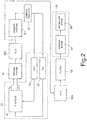
- the external driving circuitry 24 comprises, as illustrated in Figure 2 , a gain circuit 40, a phase-locked loop (PLL) 42 and an H-bridge circuit 44.
- the gain circuit 40 is connected, at input, to the external sensing circuitry 20 and thus to the system of sensing electrodes 18.
- the gain circuit 40 receives at input the first sensing signal and generates a regulation signal, which is supplied on a first input of the H-bridge circuit 44.
- the phase-locked loop 42 is also connected to the external sensing circuitry 20 for receiving the first sensing signal. Further the phase-locked loop 42 generates a phase-locked signal, which is supplied on a second input of the H-bridge circuit 44.
- the phase-locked signal has its phase locked to the phase of the velocity or else of the position of either the first mobile mass 6 or the second mobile mass 8. In what follows, it is assumed that the phase-locked signal has its phase locked to the phase of the position of the first mobile mass 6.
- the H-bridge circuit 44 generates, on the basis of the phase-locked signal and of the regulation signal, the first and second driving voltages V d1 , V d2 , which are applied to the electrodes of the system of driving electrodes 16, as described previously.
- X drive X 0 sin ⁇ d t
- X drive is the position (equivalently, the displacement), measured parallel to the axis x, assumed by the first mobile mass 6 or by the second mobile mass 8 (in what follows, for convenience, reference will be made to just the first mobile mass 6) with respect to a corresponding resting position
- X 0 is a constant amplitude value
- t is the time variable
- the phase-locked signal has a phase equal to the sum of the phase of the first sensing signal and of a deviation equal to 270°, since a further phase shift of approximately 90° is present between the phases of the driving signal (assumed as coinciding with the phase of the first driving voltage V d1 ) and the phase of X drive .
- the gain circuit 40 is a variablegain circuit, which forms a gain-control loop together with the H-bridge circuit 44, the system of driving electrodes 16, the oscillating system (the latter in Figure 2 is represented by a block 50a that indicates the mechanical transfer function H 1 (t) of the oscillating system for the driving mode, i.e., parallel to the driving direction), the system of sensing electrodes 18, and the external sensing circuitry 20.
- the gain-control loop is such that the aforementioned value X 0 is substantially constant, as mentioned previously, as well as being close to a reference value.
- the oscillating system also has a mechanical transfer function H 2 (t) for the sensing mode (i.e., parallel to the sensing direction), which sets in relation the displacements of the first and second mobile masses 6, 8 parallel to the axis z (and thus the second sensing signal) with the Coriolis force that acts, in opposite directions, on the first and second mobile masses 6, 8.
- H 2 (t) for the sensing mode (i.e., parallel to the sensing direction)
- the behaviour of the oscillating system parallel to the axis z is represented by a block 50b that indicates the mechanical transfer function H 2 (t).
- the oscillating system has been divided into:
- the output of the block 50b is connected to a system of plates 52, which is formed by the first and second conductive plates 28, 30 (illustrated in Figure 1 ). Furthermore, the processing stage 35 comprises a sensing stage 54 and an estimation stage 56.
- the sensing stage 54 is connected, at input, to the system of plates 52 and generates the aforementioned second sensing signal as a function of the variations of capacitance of the third and fourth variable capacitors.
- the output of the sensing stage 54 is connected to the input of the estimation stage 56, which transduces the second sensing signal into the aforementioned quantity proportional to the angular velocity to which the MEMS gyroscope 1 is subjected.
- the stability of MEMS gyroscopes is limited by the so-called quadrature error, which represents the error caused by undesired couplings between the so-called driving mode of the oscillating system (in the example of Figure 1 , directed parallel to the axis x and excited by the driving signal) and the so-called sensing mode (or modes) of the oscillating system (in the example of Figure 1 , directed parallel to the axis z).
- the second sensing signal available downstream of the sensing stage 54 may be viewed as the sum of a Coriolis signal, directly proportional to the Coriolis force and thus to the angular velocity to which the MEMS gyroscope 1 is subjected, and of a quadrature signal, which represents a disturbance caused by the quadrature error and is independent of the Coriolis force.
- the estimation stage 56 carries out an amplitude demodulation of a coherent type and in phase with the second sensing signal in order to filter the quadrature signal and bring the Coriolis signal down to baseband.
- output signal is meant a signal supplied by the estimation stage 56 and proportional to the angular velocity to which the MEMS gyroscope 1 is subjected. Since the changes of temperature and/or humidity and the mechanical stresses induced by the soldering process may change the relations between the phases of the signals used in the demodulation process, over time there may occur drops in performance of the gyroscope.
- gyroscopes In order to reduce at least in part the negative effects of the quadrature signal, gyroscopes have been developed with mechanical designs such as to reduce the aforementioned spurious movements, the results being, however, only partially satisfactory.
- JP 2012 255668 discloses an angular velocity sensor having a vibrator and a driving circuit for driving the vibrator by electrostatic force.
- the driving circuit comprises: a carrier wave generating circuit for generating carrier waves having a predetermined frequency; a frequency modulation circuit for modulating the frequency of the carrier waves; and a duty ratio modulation circuit for modulating a duty ratio of the carrier waves.
- the aim of the present invention is thus to provide a MEMS gyroscope that will enable the drawbacks of the known art to be overcome at least in part.
- a MEMS device is provided as defined in claim 1.
- the present gyroscope stems from an idea of the present Applicant, who has noted how it is possible to separate in frequency the Coriolis signal and the quadrature signal. In this way, filtering of the quadrature signal may be rendered independent of undesirable effects such as variations in temperature and humidity.
- MEMS gyroscope 100 illustrated in Figure 3 in which components already present in the MEMS gyroscope 1 illustrated in Figures 1 and 2 are designated by the same references, except where otherwise specified. Furthermore, in what follows, the MEMS gyroscope 100 is described limitedly to the differences with respect to the MEMS gyroscope 1 illustrated in Figures 1 and 2 .
- X drive is once again the deviation (measured parallel to the axis x) of either the first mobile mass 6 or the second mobile mass 8 with respect to a corresponding resting position
- ⁇ 0 is a parameter upon which the amount of the modulation depends
- f d 5 kHz
- f f 500 Hz.
- phase of the harmonic displacement of each of the first and second mobile masses 6, 8 is modulated so that the displacement, and thus the position of the corresponding mobile mass, is frequency modulated, with a sinusoidal modulating signal.
- first mobile mass 6 even though the following considerations also apply to the second mobile mass 8.
- X ⁇ drive X 0 cos ⁇ d t + ⁇ 0 sin ⁇ f t ⁇ d + ⁇ 0 ⁇ f cos ⁇ f t
- F Coriolis ⁇ 2 mX 0 ⁇ d + ⁇ 0 ⁇ f cos ⁇ f t ⁇ wherein F Coriolis refers to the amplitude only.
- the velocity of the first mobile mass 6, and thus also the Coriolis force depends directly upon a gain [ ⁇ d + ⁇ 0 ⁇ f cos( ⁇ f t)] of a time-variable type.
- the Coriolis force, and thus also the Coriolis signal supplied by the sensing stage 54 is modulated both in amplitude and in frequency.
- the quadrature force has a constant amplitude.
- the gain-control loop continues to keep the value X 0 , and thus the amplitude of the deviation (measured parallel to the axis x) of the first mobile mass 6 from the respective resting position, substantially constant.
- the amplitude of the quadrature force is thus equal to KX 0 .
- the quadrature force, and thus also the quadrature signal is modulated only in frequency.
- the external driving circuitry 104 comprises a phase shifter 105, the input of which is connected to the output of the phase-locked loop 42 for receiving the phase-locked signal generated thereby. Furthermore, a main output of the phase shifter 105 is connected to the second input of the H-bridge circuit 44.
- phase shifter 105 generates on its own main output a phase-shifted signal, which is supplied on the second input of the H-bridge circuit 44, instead of the phase-locked signal.
- the phase shifter 105 applies a variable time delay to the phase-locked signal, this delay being equal in modulus to ⁇ 0 sin( ⁇ f t).
- the phase-locked signal generated by the phase-locked loop 42 is a square-wave signal with a duty cycle of 50%
- the phase shifter 105 may subtract/add one or more clock beats to the duration of the half-period with a zero value of the phase-locked signal, as illustrated, for example, in Figure 4 .
- f clock 12 ⁇ f d , for simplicity of representation.
- the phase shifter 105 In practice, by varying sequentially the number of clock beats on which the half-periods with zero value of the phase-locked signal extend, the phase shifter 105 generates the phase-shifted signal.
- the phase-shifted signal is supplied on the second input of the H-bridge circuit 44, also the driving signal is phase-shifted, with respect to the phase-locked signal, by ⁇ 0 sin( ⁇ f t) so that the oscillation of the oscillating system is frequency modulated.
- the first driving voltage V d1 is phase shifted by ⁇ 0 sin( ⁇ f t) with respect to the phase-locked signal.
- Figure 5 shows, by way of example, the plots of X drive and of the corresponding derivative ⁇ drive .
- the estimation stage (designated by 156 in Figure 3 ), it implements what is illustrated in Figure 6 .
- the estimation stage 156 comprises a first demodulation stage 160, which has a first input connected to the output of the sensing stage 54, and a first filtering stage 162, the input of which is connected to the output of the first demodulation stage 160.
- the first demodulation stage 160 receives on its own first input the second sensing signal, which, as explained previously, comprises the Coriolis signal and the quadrature signal.
- the signal FMdem may be generated by the phase shifter 105 on a first secondary output of its own, to which the second input of the first demodulation stage 160 is connected.
- the first demodulation stage 160 multiplies the second sensing signal by the signal FMdem for supplying at output a first demodulated signal including a first component COMP Coriolis equal to F coriolis ⁇ H 2 (t) ⁇ FMdem, and a second component COMP quad , equal to F quad ⁇ H 2 (t) ⁇ FMdem. Examples of plots of the first and second components COMP Coriolis , COMP quad are illustrated in Figure 7 .
- the first filtering stage 162 is a filter of a low-pass type, which filters the first demodulated signal for cutting off the components of the first demodulated signal having frequencies higher than the frequency f f (in particular, it may be shown that there are present components at a frequency equal to 2 ⁇ f d , which are cut off).
- the first filtering stage 162 thus generates a first filtered signal, which includes a respective first component COMP' Coriolis , equal to K 1 [ ⁇ d + ⁇ 0 ⁇ f cos( ⁇ f t)] (with K 1 constant that depends upon the Coriolis force, but not upon the quadrature force, K 1 thus being a function, among other things, of H 2 (t) and being directly proportional to the angular velocity Q), and a respective second component COMP' quad , equal to K 2 (which is constant and depends upon the quadrature force).
- a respective first component COMP' Coriolis equal to K 1 [ ⁇ d + ⁇ 0 ⁇ f cos( ⁇ f t)] (with K 1 constant that depends upon the Coriolis force, but not upon the quadrature force, K 1 thus being a function, among other things, of H 2 (t) and being directly proportional to the angular velocity Q)
- a respective second component COMP' quad equal to K 2 (which is constant and depends upon
- the estimation stage 156 further comprises a second demodulation stage 164 and a second filtering stage 166.
- the second demodulation stage 164 multiplies the first filtered signal by the signal AMdem, and consequently carries out an amplitude demodulation of the first filtered signal, generating a second demodulated signal, which is filtered by the second filtering stage 166, which carries out a low-pass filtering with a cutoff frequency lower than the frequency f f , for keeping only a baseband component (i.e., a substantially d.c. component) of the second demodulated signal, which, as may be shown, is directly proportional to K 1 (and thus, to the angular velocity ⁇ ) and does not depend upon the quadrature force.
- the first term of the second demodulated signal that depends upon the quadrature force is around the frequency f f .
- the present MEMS gyroscope enables separation in frequency of the quadrature signal and the Coriolis signal.
- the quadrature signal may be filtered in an extremely effective way, improving the stability of the gyroscope with respect to undesirable phenomena such as the variations of temperature and humidity.
- the modulation technique implemented by the present gyroscope is irrespective of the type, number, shape, and arrangement of the electrodes of the system of driving electrodes 16 and of the system of sensing electrodes 18, as likewise of the shape and arrangement of the first and second conductive plates 28, 30, which on the other hand may also be replaced by corresponding systems of electrodes.
- the detections of the positions and of the displacements of one or more of the mobile masses may be made by sensors of a non-capacitive type, such as piezoelectric, piezoresistive, or magnetic sensors.
- the first and second mobile masses may be driven in a non-electrostatic way.
- one or more of the signals mentioned previously is of a single-ended, instead of differential, type.
- the first and second mobile masses 6, 8 may be driven just by the first driving voltage V d1 , in which case the H-bridge circuit 44 is absent and each of the first and second set of driving electrodes 17a, 17b includes only the respective first subset of electrodes.
- each of the first and second sensing signals may be of a single-ended type; for example, with reference to the first sensing signal, it may depend upon the capacitance of just one of the first and second variable capacitors.
- one or more of the signals mentioned previously may include a non-zero common-mode component, even though purely differential signals guarantee a reduced sensitivity with respect to undesirable phenomena (for example, accelerations directed parallel to the driving and sensing directions).
- phase shifter 105 and the phase-locked loop 42 may form a single circuit.
Landscapes
- Engineering & Computer Science (AREA)
- Physics & Mathematics (AREA)
- General Physics & Mathematics (AREA)
- Radar, Positioning & Navigation (AREA)
- Remote Sensing (AREA)
- Signal Processing (AREA)
- Gyroscopes (AREA)
Claims (4)
- Dispositif MEMS comprenant une puce principale (22) qui peut être fixée à une puce secondaire (2) qui comporte un cadre (4) et au moins une première masse mobile (6) couplée élastiquement au cadre, ladite puce principale (22) comportant :- un étage d'entraînement (20, 24) configuré pour entraîner, quand la puce principale est fixée à la puce secondaire, la première masse mobile de manière qu'elle oscille, parallèlement à une première direction, avec des déplacements modulés en fréquence, lesdits déplacements parallèles à la première direction variant dans le temps selon une loi sinusoïdale ayant un argument qui inclut un terme linéaire dans le temps et un terme harmonique dans le temps, ledit terme linéaire ayant un coefficient angulaire égal à une première pulsation, ledit terme harmonique ayant une deuxième pulsation ; et- un étage de traitement (35) configuré pour générer, quand la puce principale est fixée à la puce secondaire, un signal de sortie indiquant une vitesse angulaire du dispositif MEMS (100) en fonction de déplacements de la première masse mobile parallèles à une deuxième direction, quand elle est entraînée par l'étage d'entraînement, causés par une force de Coriolis qui dépend de la vitesse de la première masse mobile parallèlement à la première direction et est modulée en fréquence et en amplitude ;dans lequel l'étage d'entraînement comprend :- une circuiterie de détection (19a, 20) configurée pour générer un premier signal de détection indiquant la position de la première masse mobile (6) dans la première direction ;- un étage à verrouillage de phase (42, 105) configuré pour générer un signal de commande dont la phase est verrouillée sur la phase du premier signal de détection, à l'exception d'un déphasage temporellement variable qui dépend dudit terme harmonique dans le temps ; et- une circuiterie d'entraînement (44) configurée pour forcer le mouvement de la première masse mobile (6) parallèle à la première direction avec une force d'entraînement ayant une phase respective qui dépend de la phase dudit signal de commande ;et dans lequel l'étage de traitement comprend :- un étage de détection (54) configuré pour générer un deuxième signal de détection indiquant lesdits déplacements parallèles à la deuxième direction, ledit deuxième signal de détection incluant un signal de Coriolis, qui dépend de ladite force de Coriolis, et un signal en quadrature, qui dépend d'une force en quadrature qui agit sur la première masse mobile et dépend de la position de la première masse mobile parallèlement à la première direction, ledit signal en quadrature étant modulé en fréquence ; et- un premier étage de démodulation (160, 162) configuré pour générer un signal intermédiaire par multiplication du deuxième signal de détection par un premier signal de démodulation (FMdem), qui est un signal harmonique ayant un argument incluant un terme respectif linéaire dans le temps, qui est une fonction du terme linéaire de ladite loi sinusoïdale, et un terme respectif harmonique dans le temps, qui est une fonction du terme harmonique de ladite soi sinusoïdale, et par un premier filtrage passe-bas subséquent de manière que ledit signal intermédiaire inclue une première composante (COMPCoriolis), qui dépend de ladite force de Coriolis et est indépendante de ladite force en quadrature, et une deuxième composante (COMPquad), qui dépend de ladite force en quadrature et est indépendante de ladite force de Coriolis, ladite première composante ayant une sous-composante à fréquence élevée, ladite deuxième composante étant une composante à fréquence basse ;et dans lequel ledit étage de traitement comprend en outre un deuxième étage de démodulation (164, 166) configuré pour générer ledit signal de sortie par multiplication du signal intermédiaire par un deuxième signal de démodulation (AMdem), qui est harmonique ayant la deuxième pulsation, et par un deuxième filtrage passe-bas subséquent pour abaisser ladite sous-composante à fréquence élevée jusqu'à la bande de base.
- Dispositif MEMS selon la revendication 1, dans lequel ledit étage d'entraînement (20, 24) comprend en outre un étage de régulation de gain (40, 44), qui est configuré pour réguler l'amplitude de ladite force d'entraînement en fonction dudit premier signal de détection de manière que l'amplitude dudit premier signal de détection soit sensiblement constante.
- Gyroscope MEMS comprenant un dispositif MEMS selon l'une quelconque des revendications précédentes et ladite puce secondaire (2), dans lequel ladite puce secondaire comprend en outre une deuxième masse mobile (8) couplée élastiquement au cadre (4) et à la première masse mobile (6) ; et dans lequel ledit étage d'entraînement (20, 24) est configuré pour entraîner lesdites première et deuxième masses mobiles de manière qu'elles oscillent, parallèlement à la première direction, en opposition de phase.
- Gyroscope MEMS selon la revendication 3, dans lequel ledit premier signal de détection indique les positions des première et deuxième masses mobiles (6, 8).
Applications Claiming Priority (1)
| Application Number | Priority Date | Filing Date | Title |
|---|---|---|---|
| IT102016000098502A IT201600098502A1 (it) | 2016-09-30 | 2016-09-30 | Giroscopio mems avente elevata stabilita' nei confronti delle variazioni di temperatura e di umidita' |
Publications (2)
| Publication Number | Publication Date |
|---|---|
| EP3301398A1 EP3301398A1 (fr) | 2018-04-04 |
| EP3301398B1 true EP3301398B1 (fr) | 2019-10-16 |
Family
ID=58410211
Family Applications (1)
| Application Number | Title | Priority Date | Filing Date |
|---|---|---|---|
| EP17162662.5A Active EP3301398B1 (fr) | 2016-09-30 | 2017-03-23 | Gyroscope mems ayant une stabilité élevée par rapport aux variations de température et d'humidité |
Country Status (3)
| Country | Link |
|---|---|
| US (1) | US10488200B2 (fr) |
| EP (1) | EP3301398B1 (fr) |
| IT (1) | IT201600098502A1 (fr) |
Families Citing this family (3)
| Publication number | Priority date | Publication date | Assignee | Title |
|---|---|---|---|---|
| IT201600098502A1 (it) * | 2016-09-30 | 2018-03-30 | St Microelectronics Srl | Giroscopio mems avente elevata stabilita' nei confronti delle variazioni di temperatura e di umidita' |
| EP3882571B1 (fr) * | 2020-03-16 | 2022-08-24 | Murata Manufacturing Co., Ltd. | Gyroscope à fréquence d'oscillation secondaire verrouillée |
| FR3108897B1 (fr) | 2020-04-03 | 2022-04-08 | Commissariat Energie Atomique | Procédé de commande d’un capteur |
Family Cites Families (6)
| Publication number | Priority date | Publication date | Assignee | Title |
|---|---|---|---|---|
| FR2856789B1 (fr) * | 2003-06-27 | 2005-08-26 | Thales Sa | Gyrometre a masse vibrante |
| DE602007009090D1 (de) * | 2007-07-05 | 2010-10-21 | St Microelectronics Srl | Mikroelektromechanisches Gyroskop mit Lesevorrichtung für eine offene Schleife und Steuerverfahren dafür |
| US8783103B2 (en) * | 2009-08-21 | 2014-07-22 | Analog Devices, Inc. | Offset detection and compensation for micromachined inertial sensors |
| JP2012255668A (ja) * | 2011-06-07 | 2012-12-27 | Denso Corp | 角速度センサ |
| ITUA20162172A1 (it) * | 2016-03-31 | 2017-10-01 | St Microelectronics Srl | Sensore accelerometrico realizzato in tecnologia mems avente elevata accuratezza e ridotta sensibilita' nei confronti della temperatura e dell'invecchiamento |
| IT201600098502A1 (it) * | 2016-09-30 | 2018-03-30 | St Microelectronics Srl | Giroscopio mems avente elevata stabilita' nei confronti delle variazioni di temperatura e di umidita' |
-
2016
- 2016-09-30 IT IT102016000098502A patent/IT201600098502A1/it unknown
-
2017
- 2017-03-22 US US15/466,722 patent/US10488200B2/en active Active
- 2017-03-23 EP EP17162662.5A patent/EP3301398B1/fr active Active
Non-Patent Citations (1)
| Title |
|---|
| None * |
Also Published As
| Publication number | Publication date |
|---|---|
| IT201600098502A1 (it) | 2018-03-30 |
| EP3301398A1 (fr) | 2018-04-04 |
| US10488200B2 (en) | 2019-11-26 |
| US20180094929A1 (en) | 2018-04-05 |
Similar Documents
| Publication | Publication Date | Title |
|---|---|---|
| US7275433B2 (en) | Micro-electro-mechanical sensor with force feedback loop | |
| AU2003223779B2 (en) | Pulse width modulation drive signal for a mems gyroscope | |
| CA2548728C (fr) | Procede de compensation de la polarisation de quadrature dans un gyroscope de coriolis et gyroscope de coriolis destine a cet effet | |
| US10209270B2 (en) | Inertial sensors | |
| EP1723389B1 (fr) | Correction des erreurs pour gyromètre vibratoire | |
| EP1624285B1 (fr) | Systeme et gyroscope micro-electro-mechanique resonant | |
| US8042393B2 (en) | Arrangement for measuring a rate of rotation using a vibration sensor | |
| US5698784A (en) | Vibratory rate gyroscope and methods of assembly and operation | |
| US9869552B2 (en) | Gyroscope that compensates for fluctuations in sensitivity | |
| EP3301398B1 (fr) | Gyroscope mems ayant une stabilité élevée par rapport aux variations de température et d'humidité | |
| JP2005527783A (ja) | 電子整列および同調を有するマイクロジャイロスコープ | |
| WO1997027455A9 (fr) | Gyroscope a vitesse vibratoire et procede de montage | |
| CN1894558A (zh) | 借助转速科式陀螺测量转速/加速度的方法和实现该方法的科式陀螺 | |
| CN111024056B (zh) | 一种高动态输入的mems陀螺带宽扩展闭环控制方法 | |
| EP0683381B1 (fr) | Gyroscope à vibration | |
| EP3882571B1 (fr) | Gyroscope à fréquence d'oscillation secondaire verrouillée |
Legal Events
| Date | Code | Title | Description |
|---|---|---|---|
| PUAI | Public reference made under article 153(3) epc to a published international application that has entered the european phase |
Free format text: ORIGINAL CODE: 0009012 |
|
| STAA | Information on the status of an ep patent application or granted ep patent |
Free format text: STATUS: THE APPLICATION HAS BEEN PUBLISHED |
|
| AK | Designated contracting states |
Kind code of ref document: A1 Designated state(s): AL AT BE BG CH CY CZ DE DK EE ES FI FR GB GR HR HU IE IS IT LI LT LU LV MC MK MT NL NO PL PT RO RS SE SI SK SM TR |
|
| AX | Request for extension of the european patent |
Extension state: BA ME |
|
| STAA | Information on the status of an ep patent application or granted ep patent |
Free format text: STATUS: REQUEST FOR EXAMINATION WAS MADE |
|
| 17P | Request for examination filed |
Effective date: 20181003 |
|
| RBV | Designated contracting states (corrected) |
Designated state(s): AL AT BE BG CH CY CZ DE DK EE ES FI FR GB GR HR HU IE IS IT LI LT LU LV MC MK MT NL NO PL PT RO RS SE SI SK SM TR |
|
| GRAP | Despatch of communication of intention to grant a patent |
Free format text: ORIGINAL CODE: EPIDOSNIGR1 |
|
| STAA | Information on the status of an ep patent application or granted ep patent |
Free format text: STATUS: GRANT OF PATENT IS INTENDED |
|
| INTG | Intention to grant announced |
Effective date: 20190508 |
|
| RIN1 | Information on inventor provided before grant (corrected) |
Inventor name: GATTERE, GABRIELE Inventor name: TOCCHIO, ALESSANDRO Inventor name: VALZASINA, CARLO |
|
| GRAS | Grant fee paid |
Free format text: ORIGINAL CODE: EPIDOSNIGR3 |
|
| GRAA | (expected) grant |
Free format text: ORIGINAL CODE: 0009210 |
|
| STAA | Information on the status of an ep patent application or granted ep patent |
Free format text: STATUS: THE PATENT HAS BEEN GRANTED |
|
| AK | Designated contracting states |
Kind code of ref document: B1 Designated state(s): AL AT BE BG CH CY CZ DE DK EE ES FI FR GB GR HR HU IE IS IT LI LT LU LV MC MK MT NL NO PL PT RO RS SE SI SK SM TR |
|
| REG | Reference to a national code |
Ref country code: GB Ref legal event code: FG4D |
|
| REG | Reference to a national code |
Ref country code: CH Ref legal event code: EP |
|
| REG | Reference to a national code |
Ref country code: DE Ref legal event code: R096 Ref document number: 602017007759 Country of ref document: DE |
|
| REG | Reference to a national code |
Ref country code: IE Ref legal event code: FG4D |
|
| REG | Reference to a national code |
Ref country code: AT Ref legal event code: REF Ref document number: 1191703 Country of ref document: AT Kind code of ref document: T Effective date: 20191115 |
|
| REG | Reference to a national code |
Ref country code: NL Ref legal event code: MP Effective date: 20191016 |
|
| REG | Reference to a national code |
Ref country code: LT Ref legal event code: MG4D |
|
| REG | Reference to a national code |
Ref country code: AT Ref legal event code: MK05 Ref document number: 1191703 Country of ref document: AT Kind code of ref document: T Effective date: 20191016 |
|
| PG25 | Lapsed in a contracting state [announced via postgrant information from national office to epo] |
Ref country code: PT Free format text: LAPSE BECAUSE OF FAILURE TO SUBMIT A TRANSLATION OF THE DESCRIPTION OR TO PAY THE FEE WITHIN THE PRESCRIBED TIME-LIMIT Effective date: 20200217 Ref country code: FI Free format text: LAPSE BECAUSE OF FAILURE TO SUBMIT A TRANSLATION OF THE DESCRIPTION OR TO PAY THE FEE WITHIN THE PRESCRIBED TIME-LIMIT Effective date: 20191016 Ref country code: BG Free format text: LAPSE BECAUSE OF FAILURE TO SUBMIT A TRANSLATION OF THE DESCRIPTION OR TO PAY THE FEE WITHIN THE PRESCRIBED TIME-LIMIT Effective date: 20200116 Ref country code: GR Free format text: LAPSE BECAUSE OF FAILURE TO SUBMIT A TRANSLATION OF THE DESCRIPTION OR TO PAY THE FEE WITHIN THE PRESCRIBED TIME-LIMIT Effective date: 20200117 Ref country code: PL Free format text: LAPSE BECAUSE OF FAILURE TO SUBMIT A TRANSLATION OF THE DESCRIPTION OR TO PAY THE FEE WITHIN THE PRESCRIBED TIME-LIMIT Effective date: 20191016 Ref country code: NO Free format text: LAPSE BECAUSE OF FAILURE TO SUBMIT A TRANSLATION OF THE DESCRIPTION OR TO PAY THE FEE WITHIN THE PRESCRIBED TIME-LIMIT Effective date: 20200116 Ref country code: LV Free format text: LAPSE BECAUSE OF FAILURE TO SUBMIT A TRANSLATION OF THE DESCRIPTION OR TO PAY THE FEE WITHIN THE PRESCRIBED TIME-LIMIT Effective date: 20191016 Ref country code: SE Free format text: LAPSE BECAUSE OF FAILURE TO SUBMIT A TRANSLATION OF THE DESCRIPTION OR TO PAY THE FEE WITHIN THE PRESCRIBED TIME-LIMIT Effective date: 20191016 Ref country code: LT Free format text: LAPSE BECAUSE OF FAILURE TO SUBMIT A TRANSLATION OF THE DESCRIPTION OR TO PAY THE FEE WITHIN THE PRESCRIBED TIME-LIMIT Effective date: 20191016 Ref country code: NL Free format text: LAPSE BECAUSE OF FAILURE TO SUBMIT A TRANSLATION OF THE DESCRIPTION OR TO PAY THE FEE WITHIN THE PRESCRIBED TIME-LIMIT Effective date: 20191016 Ref country code: AT Free format text: LAPSE BECAUSE OF FAILURE TO SUBMIT A TRANSLATION OF THE DESCRIPTION OR TO PAY THE FEE WITHIN THE PRESCRIBED TIME-LIMIT Effective date: 20191016 |
|
| PG25 | Lapsed in a contracting state [announced via postgrant information from national office to epo] |
Ref country code: IS Free format text: LAPSE BECAUSE OF FAILURE TO SUBMIT A TRANSLATION OF THE DESCRIPTION OR TO PAY THE FEE WITHIN THE PRESCRIBED TIME-LIMIT Effective date: 20200224 Ref country code: RS Free format text: LAPSE BECAUSE OF FAILURE TO SUBMIT A TRANSLATION OF THE DESCRIPTION OR TO PAY THE FEE WITHIN THE PRESCRIBED TIME-LIMIT Effective date: 20191016 Ref country code: HR Free format text: LAPSE BECAUSE OF FAILURE TO SUBMIT A TRANSLATION OF THE DESCRIPTION OR TO PAY THE FEE WITHIN THE PRESCRIBED TIME-LIMIT Effective date: 20191016 |
|
| PG25 | Lapsed in a contracting state [announced via postgrant information from national office to epo] |
Ref country code: AL Free format text: LAPSE BECAUSE OF FAILURE TO SUBMIT A TRANSLATION OF THE DESCRIPTION OR TO PAY THE FEE WITHIN THE PRESCRIBED TIME-LIMIT Effective date: 20191016 |
|
| REG | Reference to a national code |
Ref country code: DE Ref legal event code: R097 Ref document number: 602017007759 Country of ref document: DE |
|
| PG2D | Information on lapse in contracting state deleted |
Ref country code: IS |
|
| PG25 | Lapsed in a contracting state [announced via postgrant information from national office to epo] |
Ref country code: DK Free format text: LAPSE BECAUSE OF FAILURE TO SUBMIT A TRANSLATION OF THE DESCRIPTION OR TO PAY THE FEE WITHIN THE PRESCRIBED TIME-LIMIT Effective date: 20191016 Ref country code: ES Free format text: LAPSE BECAUSE OF FAILURE TO SUBMIT A TRANSLATION OF THE DESCRIPTION OR TO PAY THE FEE WITHIN THE PRESCRIBED TIME-LIMIT Effective date: 20191016 Ref country code: EE Free format text: LAPSE BECAUSE OF FAILURE TO SUBMIT A TRANSLATION OF THE DESCRIPTION OR TO PAY THE FEE WITHIN THE PRESCRIBED TIME-LIMIT Effective date: 20191016 Ref country code: RO Free format text: LAPSE BECAUSE OF FAILURE TO SUBMIT A TRANSLATION OF THE DESCRIPTION OR TO PAY THE FEE WITHIN THE PRESCRIBED TIME-LIMIT Effective date: 20191016 Ref country code: CZ Free format text: LAPSE BECAUSE OF FAILURE TO SUBMIT A TRANSLATION OF THE DESCRIPTION OR TO PAY THE FEE WITHIN THE PRESCRIBED TIME-LIMIT Effective date: 20191016 Ref country code: IS Free format text: LAPSE BECAUSE OF FAILURE TO SUBMIT A TRANSLATION OF THE DESCRIPTION OR TO PAY THE FEE WITHIN THE PRESCRIBED TIME-LIMIT Effective date: 20200216 |
|
| PLBE | No opposition filed within time limit |
Free format text: ORIGINAL CODE: 0009261 |
|
| STAA | Information on the status of an ep patent application or granted ep patent |
Free format text: STATUS: NO OPPOSITION FILED WITHIN TIME LIMIT |
|
| PG25 | Lapsed in a contracting state [announced via postgrant information from national office to epo] |
Ref country code: IT Free format text: LAPSE BECAUSE OF FAILURE TO SUBMIT A TRANSLATION OF THE DESCRIPTION OR TO PAY THE FEE WITHIN THE PRESCRIBED TIME-LIMIT Effective date: 20191016 Ref country code: SM Free format text: LAPSE BECAUSE OF FAILURE TO SUBMIT A TRANSLATION OF THE DESCRIPTION OR TO PAY THE FEE WITHIN THE PRESCRIBED TIME-LIMIT Effective date: 20191016 Ref country code: SK Free format text: LAPSE BECAUSE OF FAILURE TO SUBMIT A TRANSLATION OF THE DESCRIPTION OR TO PAY THE FEE WITHIN THE PRESCRIBED TIME-LIMIT Effective date: 20191016 |
|
| 26N | No opposition filed |
Effective date: 20200717 |
|
| PG25 | Lapsed in a contracting state [announced via postgrant information from national office to epo] |
Ref country code: MC Free format text: LAPSE BECAUSE OF FAILURE TO SUBMIT A TRANSLATION OF THE DESCRIPTION OR TO PAY THE FEE WITHIN THE PRESCRIBED TIME-LIMIT Effective date: 20191016 |
|
| REG | Reference to a national code |
Ref country code: CH Ref legal event code: PL |
|
| PG25 | Lapsed in a contracting state [announced via postgrant information from national office to epo] |
Ref country code: SI Free format text: LAPSE BECAUSE OF FAILURE TO SUBMIT A TRANSLATION OF THE DESCRIPTION OR TO PAY THE FEE WITHIN THE PRESCRIBED TIME-LIMIT Effective date: 20191016 |
|
| REG | Reference to a national code |
Ref country code: BE Ref legal event code: MM Effective date: 20200331 |
|
| PG25 | Lapsed in a contracting state [announced via postgrant information from national office to epo] |
Ref country code: LU Free format text: LAPSE BECAUSE OF NON-PAYMENT OF DUE FEES Effective date: 20200323 |
|
| PG25 | Lapsed in a contracting state [announced via postgrant information from national office to epo] |
Ref country code: LI Free format text: LAPSE BECAUSE OF NON-PAYMENT OF DUE FEES Effective date: 20200331 Ref country code: CH Free format text: LAPSE BECAUSE OF NON-PAYMENT OF DUE FEES Effective date: 20200331 Ref country code: IE Free format text: LAPSE BECAUSE OF NON-PAYMENT OF DUE FEES Effective date: 20200323 Ref country code: FR Free format text: LAPSE BECAUSE OF NON-PAYMENT OF DUE FEES Effective date: 20200331 |
|
| PG25 | Lapsed in a contracting state [announced via postgrant information from national office to epo] |
Ref country code: BE Free format text: LAPSE BECAUSE OF NON-PAYMENT OF DUE FEES Effective date: 20200331 |
|
| GBPC | Gb: european patent ceased through non-payment of renewal fee |
Effective date: 20210323 |
|
| PG25 | Lapsed in a contracting state [announced via postgrant information from national office to epo] |
Ref country code: GB Free format text: LAPSE BECAUSE OF NON-PAYMENT OF DUE FEES Effective date: 20210323 |
|
| PG25 | Lapsed in a contracting state [announced via postgrant information from national office to epo] |
Ref country code: TR Free format text: LAPSE BECAUSE OF FAILURE TO SUBMIT A TRANSLATION OF THE DESCRIPTION OR TO PAY THE FEE WITHIN THE PRESCRIBED TIME-LIMIT Effective date: 20191016 Ref country code: MT Free format text: LAPSE BECAUSE OF FAILURE TO SUBMIT A TRANSLATION OF THE DESCRIPTION OR TO PAY THE FEE WITHIN THE PRESCRIBED TIME-LIMIT Effective date: 20191016 Ref country code: CY Free format text: LAPSE BECAUSE OF FAILURE TO SUBMIT A TRANSLATION OF THE DESCRIPTION OR TO PAY THE FEE WITHIN THE PRESCRIBED TIME-LIMIT Effective date: 20191016 |
|
| PG25 | Lapsed in a contracting state [announced via postgrant information from national office to epo] |
Ref country code: MK Free format text: LAPSE BECAUSE OF FAILURE TO SUBMIT A TRANSLATION OF THE DESCRIPTION OR TO PAY THE FEE WITHIN THE PRESCRIBED TIME-LIMIT Effective date: 20191016 |
|
| PGFP | Annual fee paid to national office [announced via postgrant information from national office to epo] |
Ref country code: DE Payment date: 20240220 Year of fee payment: 8 |