EP3301059A1 - Compensation chain stabilize device and method, hoistway and elevator system - Google Patents
Compensation chain stabilize device and method, hoistway and elevator system Download PDFInfo
- Publication number
- EP3301059A1 EP3301059A1 EP17192100.0A EP17192100A EP3301059A1 EP 3301059 A1 EP3301059 A1 EP 3301059A1 EP 17192100 A EP17192100 A EP 17192100A EP 3301059 A1 EP3301059 A1 EP 3301059A1
- Authority
- EP
- European Patent Office
- Prior art keywords
- compensation chain
- magnetic field
- field generating
- generating device
- stabilizing apparatus
- Prior art date
- Legal status (The legal status is an assumption and is not a legal conclusion. Google has not performed a legal analysis and makes no representation as to the accuracy of the status listed.)
- Granted
Links
Images
Classifications
-
- B—PERFORMING OPERATIONS; TRANSPORTING
- B66—HOISTING; LIFTING; HAULING
- B66B—ELEVATORS; ESCALATORS OR MOVING WALKWAYS
- B66B11/00—Main component parts of lifts in, or associated with, buildings or other structures
- B66B11/0005—Constructional features of hoistways
-
- B—PERFORMING OPERATIONS; TRANSPORTING
- B66—HOISTING; LIFTING; HAULING
- B66B—ELEVATORS; ESCALATORS OR MOVING WALKWAYS
- B66B17/00—Hoistway equipment
- B66B17/12—Counterpoises
-
- B—PERFORMING OPERATIONS; TRANSPORTING
- B66—HOISTING; LIFTING; HAULING
- B66B—ELEVATORS; ESCALATORS OR MOVING WALKWAYS
- B66B7/00—Other common features of elevators
- B66B7/06—Arrangements of ropes or cables
- B66B7/068—Cable weight compensating devices
-
- B—PERFORMING OPERATIONS; TRANSPORTING
- B66—HOISTING; LIFTING; HAULING
- B66B—ELEVATORS; ESCALATORS OR MOVING WALKWAYS
- B66B7/00—Other common features of elevators
- B66B7/12—Checking, lubricating, or cleaning means for ropes, cables or guides
- B66B7/1207—Checking means
- B66B7/1215—Checking means specially adapted for ropes or cables
- B66B7/1238—Checking means specially adapted for ropes or cables by optical techniques
-
- B—PERFORMING OPERATIONS; TRANSPORTING
- B66—HOISTING; LIFTING; HAULING
- B66B—ELEVATORS; ESCALATORS OR MOVING WALKWAYS
- B66B9/00—Kinds or types of lifts in, or associated with, buildings or other structures
Definitions
- the present invention relates to the field of elevator technologies, and in particular, to a compensation chain stabilizing apparatus and method for an elevator, and an elevator shaft and elevator system having the compensation chain stabilizing apparatus or using the compensation chain stabilizing method.
- a compensation chain is disposed between a car and the bottom of a counterweight support.
- the compensation chain generally includes a compensation chain body consisting of metal and a protective layer which wraps the compensation chain body and consists of, for example, a PVC rubber composite material.
- the compensation chain may shake during a startup or braking process or an acceleration or deceleration process of the elevator. Due to the shaking, the compensation chain may hit a buffer support or another mechanism provided at the bottom of an elevator shaft, which may thus generate noise. In some extreme conditions, the compensation chain may even hit the car.
- An objective of the present invention is to solve or at least mitigate the problem existing in the prior art.
- Another objective of the present invention is to provide a compensation chain stabilizing apparatus and method, and an elevator shaft and elevator system using such a compensation chain stabilizing apparatus or method, thereby suppressing shaking of the compensation chain as much as possible, and solving or at least mitigating other problems related to the shaking of the compensation chain.
- a compensation chain stabilizing apparatus for an elevator.
- the compensation chain stabilizing apparatus includes a magnetic field generating device, and the magnetic field generating device is configured to generate a magnetic field to limit shaking of the compensation chain.
- Particular embodiments may include any of the following optional features, alone or in combination:
- the magnetic field generating device may be an electromagnet.
- the compensation chain stabilizing apparatus further may comprise a sensor configured to sense an operation status of an elevator car.
- the compensation chain stabilizing apparatus further may comprise a sensor configured to sense a status of the compensation chain.
- the sensor may be an optical sensor, so as to sense a shaking amplitude and/or position of the compensation chain.
- the compensation chain stabilizing apparatus further may comprises a control device, and the control device may controls the electromagnet based on the status of the compensation chain.
- the compensation chain stabilizing apparatus further may comprise an isolating device configured to isolate the magnetic field generating device from the compensation chain.
- the isolating device may be an isolating plate, an isolating cover or an isolating net.
- the isolating device may have a smooth surface facing the compensation chain.
- the isolating device may be made of a glass material.
- the compensation chain stabilizing apparatus further may comprise a position adjustment device.
- the position adjustment device may be able to adjust a vertical height of the magnetic field generating device.
- the position adjustment device may adjust a horizontal position of the magnetic field generating device.
- the position adjustment device may be an adjustable support disposed at the bottom of the magnetic field generating device.
- an elevator shaft and an elevator system are provided, which include the compensation chain stabilizing apparatus according to an embodiment of the present invention.
- Particular embodiments may include any of the following optional features, alone or in combination:
- a magnetic field generating device of the compensation chain stabilizing apparatus max be aligned with a bottom U-shaped region of the compensation chain in a vertical direction.
- An elevator system may comprise a shaft, a car in the shaft, a counterweight support, and a compensation chain installed between the car and the bottom of the counterweight support, the compensation chain being at least partially made of a magnetic material, wherein the elevator system further comprises one or more compensation chain stabilizing apparatuses as described herein.
- the compensation chain stabilizing apparatus may comprise a magnetic field generating device, and the magnetic field generating device may be configured to generate a magnetic field to limit shaking of the compensation chain.
- the elevator system may have at least one compensation chain stabilizing apparatus which is disposed at the bottom of the shaft and corresponds to the position of the compensation chain.
- the magnetic field generating device of the compensation chain stabilizing apparatus may be aligned with a bottom U-shaped region of the compensation chain in a vertical direction.
- a method for preventing shaking of a compensation chain includes: using a compensation chain at least partially made of a magnetic material, and disposing a magnetic field generating device near the compensation chain to limit shaking of the compensation chain.
- Particular embodiments may include any of the following optional features, alone or in combination:
- the method further may comprise disposing an isolating device between the magnetic field generating device and the compensation chain.
- the method further may comprise disposing an isolating plate or an isolating cover, which has a smooth surface facing the compensation chain, between the magnetic field generating device and the compensation chain.
- the method further may comprise adjusting a vertical height of the magnetic field generating device by using an adjustable support capable of adjusting a height in a vertical direction.
- the method further may comprises using a permanent magnet as the magnetic field generating device.
- the method further may comprise using an electromagnet as the magnetic field generating device.
- the method further may comprise operating the electromagnet based on an operation status of a car or a status of the compensation chain.
- orientation terms mentioned or possibly mentioned in the specification such as upper, lower, left, right, front, rear, front surface, back surface, top, and bottom are defined relative to the structure shown in the accompanying drawing.
- the orientation terms are relative concepts, and therefore may change correspondingly according to different positions or different use statuses. Therefore, these or other orientation terms should not be interpreted as restrictive terms.
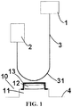
- an elevator system includes a car 1, a counterweight support 2, and a compensation chain 3 suspended between the car 1 and the bottom of the counterweight support 2.
- the compensation chain 3 is used to offset the weight of an elevator traction rope.
- the compensation chain 3 generally includes a metal chain body and a protective layer wrapping the metal chain body.
- the metal chain body is generally made of iron or other magnetic materials.
- the protective layer may be made of a composite material such as PVC rubber.
- the compensation chain 3 includes a vertical portion under the car 1 and the counterweight support 2 and a U-shaped region 31 at the bottom of the compensation chain 3.
- the elevator system further includes at least one compensation chain stabilizing apparatus 10 according to the present invention.
- the compensation chain stabilizing apparatus 10 according to the present invention includes a magnetic field generating device 12.
- the magnetic field generating device 12 can generate a magnetic field which acts on the compensation chain 3. Specifically, the magnetic field may attract the compensation chain 3, thus straining the compensation chain 3, to prevent shaking of the compensation chain 3.
- FIG. 1 only one compensation chain stabilizing apparatus 10 is shown in FIG. 1 , multiple compensation chain stabilizing apparatuses 10 may be disposed at different positions in an alternative embodiment. In the embodiment shown in FIG. 1 , the compensation chain stabilizing apparatus 10 is disposed under the compensation chain 12.
- the compensation chain stabilizing apparatus 10 may further be disposed at another different position, as long as the magnetic field generated by the magnetic field generating device 12 of the compensation chain stabilizing apparatus 10 makes the compensation chain 3 tensioned, so that the compensation chain 3 does not shake easily.
- two magnetic field generating devices 12 may be disposed on front and rear sides of the compensation chain 3 in FIG. 1 , so that the compensation chain presents between the two magnetic field generating devices 12. In other words, the compensation chain 3 is sandwiched between the two magnetic field generating devices 12.
- the magnetic field generating device 12 may be a permanent magnet, such as magnetic iron.
- the magnetic field generated by the magnetic iron continuously acts on the compensation chain 3, and specifically attracts the compensation chain 3 at least partially made of a magnetic material, thereby straining the compensation chain 3, to prevent shaking of the compensation chain 3.
- the magnetic field generating device 12 may be an electromagnet, such as an electrified solenoid coil. The presence of the magnetic field or the intensity of the magnetic field may be controlled by means of on/off control or magnitude control of a current flowing through the electrified solenoid coil.
- the compensation chain stabilizing apparatus 10 may include multiple sensors configured to sense an operation status of the elevator car 1 and a status of the compensation chain 3.
- the magnitude of the current flowing through the electrified solenoid coil may be controlled in response to the operation status of the elevator car 1, thus controlling the presence of the magnetic field or the intensity of the magnetic field. For example, when it is sensed that the elevator car 1 remains stopped or off for a long time or when it is sensed that the elevator operates at a constant speed, the magnetic field is reduced or turned off. When the elevator accelerates, decelerates, starts up, or brakes, the magnetic field is increased to limit shaking of the compensation chain.
- one or more sensors configured to sense the status of the compensation chain may be disposed, for example, a sensor configured to sense the position or displacement of the compensation chain. These sensors may be optical-based sensors.
- the optical sensor includes an optical emitter and an optical receiver.
- the sensor is disposed in such a manner that when shaking of the compensation chain reaches a particular amplitude, the compensation chain obstructs light so that the optical receiver cannot receive light, thus feeding back the shaking amplitude of the compensation chain.
- the sensor may be disposed in such a manner that when shaking of the compensation chain reaches a particular amplitude, the compensation chain leaves to allow light to pass through, so that the optical receiver can receive light, thus feeding back the shaking amplitude of the compensation chain.
- the sensor may also be a camera sensor or a non-contact-type or contact-type position or displacement sensor based on other principles.
- the magnitude of the current flowing through the electrified solenoid coil may be controlled on the basis of the status (such as a position or displacement status) of the compensation chain sensed by the sensor, thus controlling the presence of the magnetic field or the intensity of the magnetic field. For example, the magnetic field is reduced or turned off when it is sensed that the shaking amplitude of the compensation chain is relatively small, and the magnetic field is increased when it is sensed that the shaking amplitude of the compensation chain is relatively large, so as to limit the shaking of the compensation chain.
- an isolating device is disposed between the magnetic field generating device 12 and the compensation chain 3.
- an isolating cover 13 as shown in the figure may be used. The presence of the isolating cover 13 prevents direct contact between the compensation chain 3 and the magnetic field generating device 12. If the magnetic field generating device 12 is in direct contact with the compensation chain 3, an attractive force between the two may cause a relatively large friction between the two during movement of the compensation chain. The friction may abrade the compensation chain protective layer wrapping the compensation chain body, which is undesired, and the isolating device prevents occurrence of such a situation.
- the isolating device should be made of a material that does not affect or hardly affects the magnetic field generated by the magnetic field generating device 12, or should be formed as a non-enclosed structure, such as a net-shaped structure or a structure having a hole. In this way, the isolating device does not affect the magnetic field generated by the magnetic field generating device 12.
- the isolating device may also be other types of devices such as an isolating plate or an isolating net installed between the magnetic field generating device 12 and the compensation chain 3.
- the isolating device may also be a laminate or a layer applied on a surface facing the compensation chain 3 of the magnetic field generating device 12.
- the magnetic field generating device In order to maximize the effect of the magnetic field generated by the magnetic field generating device 12, the magnetic field generating device inevitably needs to be as close to the compensation chain 3 as possible.
- a distance between the isolating device and the magnetic field generating device may be adjusted, thereby adjusting a minimum distance between the magnetic field generating device and the compensation chain, so that the intensity of the magnetic field at the position of the compensation chain is adjusted.
- at least the surface of the isolating device facing the compensation chain 3 is a smooth surface.
- the isolating device may be made of a glass material, for example, an isolating cover or isolating plate made of a glass material, and so on.
- the compensation chain stabilizing apparatus 10 further includes a position adjustment device 11 for adjusting the position of the magnetic field generating device 12.
- the position adjustment device 11 may be an adjustable support on which the magnetic field generating device 12 can be arranged.
- the adjustable support can at least adjust a height position of the magnetic field generating device 12 in a vertical direction, so that the magnetic field of the magnetic field generating device 12 can be disposed at a suitable height, to facilitate adjustment of the intensity of the magnetic field at the position of the compensation chain 11.
- the adjustable support may further adjust a vertical position of the magnetic field generating device 12 relative to the isolating cover 13, to facilitate adjustment of a distance between the magnetic field generating device 12 and the isolating cover 13, thus adjusting the intensity of the magnetic field acting on the compensation chain 3.
- the height of the compensation chain 3 may have a certain installation error, and the compensation chain stabilizing apparatus provided with the adjustable support can apply to various on-site situations. The presence of the adjustable support ensures that the distance between the magnetic field generating apparatus and the compensation chain is in a suitable range.
- the position adjustment device 11 may also adjust the position of the magnetic field generating device 12 on other degrees of freedom. For example, the position adjustment device 11 may further adjust a position of the magnetic field generating device 12 in a horizontal plane, so that the magnetic field generating device 12 is aligned with the bottom U-shaped region 31 of the compensation chain 3, or the magnetic field generating device 12 is adjusted to another appropriate position.
- the maximum shaking amplitude of the compensation chain appears in the bottom U-shaped region 31 at the bottom of the compensation chain.
- the shaking amplitude of the compensation chain is maximum, and the compensation chain may hit a buffer support also at the bottom of the shaft or another device at the bottom of the shaft. Therefore, preferably, the magnetic field of the magnetic field generating device 12 is enabled to be applied on the bottom U-shaped region 31 of the compensation chain.
- the magnetic field generating device 12 may be disposed near the bottom U-shaped region 31 of the compensation chain, for example, under or on two sides of the bottom U-shaped region 31.
- the position of the magnetic field generating device 12 in a horizontal direction may be adjusted by using the adjustment device 11, so that the magnetic field generating device 12 is aligned with the bottom U-shaped region 31 of the compensation chain in the vertical direction or is positioned at an appropriate position on two sides of the bottom U-shaped region 31 of the compensation chain 3.
- a buffer support is further provided at the bottom of the shaft, and the compensation chain stabilizing apparatus 10 may be arranged near the buffer support, for example, on a side surface of or in front or rear of the buffer support.
- an elevator shaft is further provided.
- One or more compensation chain stabilizing apparatuses 10 are disposed in the elevator shaft.
- the compensation chain stabilizing apparatus 10 may be disposed at a bottom position or another position of the shaft.
- the presence of the compensation chain stabilizing apparatus 10 can prevent large-amplitude shaking of the compensation chain in the shaft.
- the compensation chain In tests, in a shaft with the compensation chain stabilizing apparatus provided at the bottom, the compensation chain only shakes once or twice with a small amplitude when the elevator car brakes, and then stops shaking. The small-amplitude shaking does not affect other facilities in the elevator shaft.
- the elevator shaft has at least one compensation chain stabilizing apparatus 10 which is disposed at the bottom of the shaft and corresponds to the position of the compensation chain.
- the compensation chain stabilizing apparatus 10 is disposed near the bottom U-shaped region 31 of the compensation chain, for example, under the bottom U-shaped region 31 of the compensation chain or at an appropriate position on two sides thereof.
- the magnetic field generating device 12 of the compensation chain stabilizing apparatus 10 is aligned with the bottom U-shaped region 31 of the compensation chain in the vertical direction.
- an elevator system is further provided.
- the elevator system includes a shaft.
- the shaft is provided with a car 1, a counterweight support 2, and a compensation chain 3 installed between the car 1 and the bottom of the counterweight support 2.
- the compensation chain 3 is at least partially made of a magnetic material.
- the elevator system further includes one or more compensation chain stabilizing apparatuses 10 according to the embodiments of the present invention.
- the compensation chain stabilizing apparatus 10 includes a magnetic field generating device 12 which is configured to generate a magnetic field to limit shaking of the compensation chain 3.
- the elevator system has at least one compensation chain stabilizing apparatus 10 which is disposed at the bottom of the shaft and corresponds to the position of the compensation chain 3.
- the magnetic field generating device 12 of the compensation chain stabilizing apparatus 10 is aligned with the bottom U-shaped region 31 of the compensation chain in the vertical direction.
- a method for preventing shaking of a compensation chain in an elevator system includes: using a compensation chain at least partially made of a magnetic material, and disposing a magnetic field generating device near the compensation chain to limit shaking of the compensation chain.
- the method further includes disposing the magnetic field generating device at the bottom of a shaft and aligning the magnetic field generating device with a bottom U-shaped region of the compensation chain.
- the method further includes disposing an isolating device between the magnetic field generating device and the compensation chain.
- the method further includes disposing an isolating plate or an isolating cover, which has a smooth surface facing the compensation chain, between the magnetic field generating device and the compensation chain.
- the method further includes adjusting a height position of the magnetic field generating device by using an adjustable support capable of adjusting a height in a vertical direction.
- the method includes using a permanent magnet as the magnetic field generating device.
- the method includes using an electromagnet as the magnetic field generating device.
- the method includes operating the electromagnet based on an operation status of a car or a status of the compensation chain.
Landscapes
- Engineering & Computer Science (AREA)
- Structural Engineering (AREA)
- Civil Engineering (AREA)
- Mechanical Engineering (AREA)
- Automation & Control Theory (AREA)
- Lift-Guide Devices, And Elevator Ropes And Cables (AREA)
Abstract
Description
- The present invention relates to the field of elevator technologies, and in particular, to a compensation chain stabilizing apparatus and method for an elevator, and an elevator shaft and elevator system having the compensation chain stabilizing apparatus or using the compensation chain stabilizing method.
- During lifting of an elevator, in order to offset a change in the weight of an elevator traction rope as the elevator moves to different positions, a compensation chain is disposed between a car and the bottom of a counterweight support. The compensation chain generally includes a compensation chain body consisting of metal and a protective layer which wraps the compensation chain body and consists of, for example, a PVC rubber composite material. The compensation chain may shake during a startup or braking process or an acceleration or deceleration process of the elevator. Due to the shaking, the compensation chain may hit a buffer support or another mechanism provided at the bottom of an elevator shaft, which may thus generate noise. In some extreme conditions, the compensation chain may even hit the car.
- An objective of the present invention is to solve or at least mitigate the problem existing in the prior art.
- Another objective of the present invention is to provide a compensation chain stabilizing apparatus and method, and an elevator shaft and elevator system using such a compensation chain stabilizing apparatus or method, thereby suppressing shaking of the compensation chain as much as possible, and solving or at least mitigating other problems related to the shaking of the compensation chain.
- According to an aspect of the present invention, a compensation chain stabilizing apparatus for an elevator is provided. The compensation chain stabilizing apparatus includes a magnetic field generating device, and the magnetic field generating device is configured to generate a magnetic field to limit shaking of the compensation chain.
- Particular embodiments may include any of the following optional features, alone or in combination:
- The magnetic field generating device is may be permanent magnet.
- The magnetic field generating device may be an electromagnet.
- The compensation chain stabilizing apparatus further may comprise a sensor configured to sense an operation status of an elevator car.
- The compensation chain stabilizing apparatus further may comprise a sensor configured to sense a status of the compensation chain.
- The sensor may be an optical sensor, so as to sense a shaking amplitude and/or position of the compensation chain.
- The compensation chain stabilizing apparatus further may comprises a control device, and the control device may controls the electromagnet based on the status of the compensation chain.
- The compensation chain stabilizing apparatus further may comprise an isolating device configured to isolate the magnetic field generating device from the compensation chain.
- The isolating device may be an isolating plate, an isolating cover or an isolating net.
- The isolating device may have a smooth surface facing the compensation chain.
- The isolating device may be made of a glass material.
- The compensation chain stabilizing apparatus further may comprise a position adjustment device.
- The position adjustment device may be able to adjust a vertical height of the magnetic field generating device.
- The position adjustment device may adjust a horizontal position of the magnetic field generating device.
- The position adjustment device may be an adjustable support disposed at the bottom of the magnetic field generating device.
- According to another aspect of the present invention, an elevator shaft and an elevator system are provided, which include the compensation chain stabilizing apparatus according to an embodiment of the present invention.
- Particular embodiments may include any of the following optional features, alone or in combination:
- The elevator shaft may have at least one compensation chain stabilizing apparatus which is disposed at the bottom of the shaft and corresponds to the position of the compensation chain.
- A magnetic field generating device of the compensation chain stabilizing apparatus max be aligned with a bottom U-shaped region of the compensation chain in a vertical direction.
- An elevator system may comprise a shaft, a car in the shaft, a counterweight support, and a compensation chain installed between the car and the bottom of the counterweight support, the compensation chain being at least partially made of a magnetic material, wherein the elevator system further comprises one or more compensation chain stabilizing apparatuses as described herein. The compensation chain stabilizing apparatus may comprise a magnetic field generating device, and the magnetic field generating device may be configured to generate a magnetic field to limit shaking of the compensation chain.
- The elevator system may have at least one compensation chain stabilizing apparatus which is disposed at the bottom of the shaft and corresponds to the position of the compensation chain.
- The magnetic field generating device of the compensation chain stabilizing apparatus may be aligned with a bottom U-shaped region of the compensation chain in a vertical direction.
- According to another aspect of the present invention, a method for preventing shaking of a compensation chain is provided. The method includes: using a compensation chain at least partially made of a magnetic material, and disposing a magnetic field generating device near the compensation chain to limit shaking of the compensation chain.
- Particular embodiments may include any of the following optional features, alone or in combination:
- The method further may comprise disposing the magnetic field generating device at the bottom of a shaft and aligning the magnetic field generating device with a bottom U-shaped region of the compensation chain.
- The method further may comprise disposing an isolating device between the magnetic field generating device and the compensation chain.
- The method further may comprise disposing an isolating plate or an isolating cover, which has a smooth surface facing the compensation chain, between the magnetic field generating device and the compensation chain.
- The method further may comprise adjusting a vertical height of the magnetic field generating device by using an adjustable support capable of adjusting a height in a vertical direction.
- The method further may comprises using a permanent magnet as the magnetic field generating device.
- The method further may comprise using an electromagnet as the magnetic field generating device.
- The method further may comprise operating the electromagnet based on an operation status of a car or a status of the compensation chain.
- The foregoing and other features of the present invention will become obvious with reference to the accompanying drawing, where:
-
FIG. 1 is a schematic structural diagram of an elevator system according to an embodiment of the present invention. - It is easy to understand that, according to the technical solution of the present invention, those of ordinary skill in the art can propose multiple interchangeable structures and implementations without changing the essential spirit of the present invention. Therefore, the following specific implementations and accompanying drawing are merely exemplary description of the technical solution of the present invention, but should not be regarded as all of the present invention or limitations or restrictions on the technical solution of the present invention.
- Orientation terms mentioned or possibly mentioned in the specification, such as upper, lower, left, right, front, rear, front surface, back surface, top, and bottom are defined relative to the structure shown in the accompanying drawing. The orientation terms are relative concepts, and therefore may change correspondingly according to different positions or different use statuses. Therefore, these or other orientation terms should not be interpreted as restrictive terms.
- As shown in
FIG. 1 , an elevator system according to an embodiment of the present invention includes a car 1, a counterweight support 2, and a compensation chain 3 suspended between the car 1 and the bottom of the counterweight support 2. The compensation chain 3 is used to offset the weight of an elevator traction rope. The compensation chain 3 generally includes a metal chain body and a protective layer wrapping the metal chain body. The metal chain body is generally made of iron or other magnetic materials. The protective layer may be made of a composite material such as PVC rubber. As shown in the figure, the compensation chain 3 includes a vertical portion under the car 1 and the counterweight support 2 and aU-shaped region 31 at the bottom of the compensation chain 3. Other parts of the elevator system are not the focus of the present invention, and therefore are not depicted herein or described in detail in the present invention. Those skilled in the art should understand that any existing or non-existing structures in the art may be used for other parts of the elevator system as required. - The elevator system further includes at least one compensation
chain stabilizing apparatus 10 according to the present invention. The compensationchain stabilizing apparatus 10 according to the present invention includes a magneticfield generating device 12. The magneticfield generating device 12 can generate a magnetic field which acts on the compensation chain 3. Specifically, the magnetic field may attract the compensation chain 3, thus straining the compensation chain 3, to prevent shaking of the compensation chain 3. Although only one compensationchain stabilizing apparatus 10 is shown inFIG. 1 , multiple compensationchain stabilizing apparatuses 10 may be disposed at different positions in an alternative embodiment. In the embodiment shown inFIG. 1 , the compensationchain stabilizing apparatus 10 is disposed under thecompensation chain 12. In an alternative embodiment, the compensationchain stabilizing apparatus 10 may further be disposed at another different position, as long as the magnetic field generated by the magneticfield generating device 12 of the compensationchain stabilizing apparatus 10 makes the compensation chain 3 tensioned, so that the compensation chain 3 does not shake easily. In some embodiments, two magneticfield generating devices 12 may be disposed on front and rear sides of the compensation chain 3 inFIG. 1 , so that the compensation chain presents between the two magneticfield generating devices 12. In other words, the compensation chain 3 is sandwiched between the two magneticfield generating devices 12. - In some embodiments, the magnetic
field generating device 12 may be a permanent magnet, such as magnetic iron. The magnetic field generated by the magnetic iron continuously acts on the compensation chain 3, and specifically attracts the compensation chain 3 at least partially made of a magnetic material, thereby straining the compensation chain 3, to prevent shaking of the compensation chain 3. In some other embodiments, the magneticfield generating device 12 may be an electromagnet, such as an electrified solenoid coil. The presence of the magnetic field or the intensity of the magnetic field may be controlled by means of on/off control or magnitude control of a current flowing through the electrified solenoid coil. In some embodiments, the compensationchain stabilizing apparatus 10 may include multiple sensors configured to sense an operation status of the elevator car 1 and a status of the compensation chain 3. In some embodiments, the magnitude of the current flowing through the electrified solenoid coil may be controlled in response to the operation status of the elevator car 1, thus controlling the presence of the magnetic field or the intensity of the magnetic field. For example, when it is sensed that the elevator car 1 remains stopped or off for a long time or when it is sensed that the elevator operates at a constant speed, the magnetic field is reduced or turned off. When the elevator accelerates, decelerates, starts up, or brakes, the magnetic field is increased to limit shaking of the compensation chain. In some embodiments, one or more sensors configured to sense the status of the compensation chain may be disposed, for example, a sensor configured to sense the position or displacement of the compensation chain. These sensors may be optical-based sensors. Specifically, the optical sensor includes an optical emitter and an optical receiver. The sensor is disposed in such a manner that when shaking of the compensation chain reaches a particular amplitude, the compensation chain obstructs light so that the optical receiver cannot receive light, thus feeding back the shaking amplitude of the compensation chain. Alternatively, the sensor may be disposed in such a manner that when shaking of the compensation chain reaches a particular amplitude, the compensation chain leaves to allow light to pass through, so that the optical receiver can receive light, thus feeding back the shaking amplitude of the compensation chain. In other embodiments, the sensor may also be a camera sensor or a non-contact-type or contact-type position or displacement sensor based on other principles. In some embodiments, the magnitude of the current flowing through the electrified solenoid coil may be controlled on the basis of the status (such as a position or displacement status) of the compensation chain sensed by the sensor, thus controlling the presence of the magnetic field or the intensity of the magnetic field. For example, the magnetic field is reduced or turned off when it is sensed that the shaking amplitude of the compensation chain is relatively small, and the magnetic field is increased when it is sensed that the shaking amplitude of the compensation chain is relatively large, so as to limit the shaking of the compensation chain. - In some embodiments, an isolating device is disposed between the magnetic
field generating device 12 and the compensation chain 3. For example, in some embodiments, an isolatingcover 13 as shown in the figure may be used. The presence of the isolatingcover 13 prevents direct contact between the compensation chain 3 and the magneticfield generating device 12. If the magneticfield generating device 12 is in direct contact with the compensation chain 3, an attractive force between the two may cause a relatively large friction between the two during movement of the compensation chain. The friction may abrade the compensation chain protective layer wrapping the compensation chain body, which is undesired, and the isolating device prevents occurrence of such a situation. In some embodiments, the isolating device should be made of a material that does not affect or hardly affects the magnetic field generated by the magneticfield generating device 12, or should be formed as a non-enclosed structure, such as a net-shaped structure or a structure having a hole. In this way, the isolating device does not affect the magnetic field generated by the magneticfield generating device 12. In some embodiments, the isolating device may also be other types of devices such as an isolating plate or an isolating net installed between the magneticfield generating device 12 and the compensation chain 3. In some embodiments, the isolating device may also be a laminate or a layer applied on a surface facing the compensation chain 3 of the magneticfield generating device 12. In order to maximize the effect of the magnetic field generated by the magneticfield generating device 12, the magnetic field generating device inevitably needs to be as close to the compensation chain 3 as possible. In some embodiments, a distance between the isolating device and the magnetic field generating device may be adjusted, thereby adjusting a minimum distance between the magnetic field generating device and the compensation chain, so that the intensity of the magnetic field at the position of the compensation chain is adjusted. To minimize the friction between the magnetic field generating device and the compensation chain, in some embodiments, at least the surface of the isolating device facing the compensation chain 3 is a smooth surface. In some embodiments, the isolating device may be made of a glass material, for example, an isolating cover or isolating plate made of a glass material, and so on. - In some embodiments, the compensation
chain stabilizing apparatus 10 further includes aposition adjustment device 11 for adjusting the position of the magneticfield generating device 12. For example, in some embodiments, theposition adjustment device 11 may be an adjustable support on which the magneticfield generating device 12 can be arranged. The adjustable support can at least adjust a height position of the magneticfield generating device 12 in a vertical direction, so that the magnetic field of the magneticfield generating device 12 can be disposed at a suitable height, to facilitate adjustment of the intensity of the magnetic field at the position of thecompensation chain 11. In some embodiments, the adjustable support may further adjust a vertical position of the magneticfield generating device 12 relative to the isolatingcover 13, to facilitate adjustment of a distance between the magneticfield generating device 12 and the isolatingcover 13, thus adjusting the intensity of the magnetic field acting on the compensation chain 3. During installation of the compensation chain 3, the height of the compensation chain 3 may have a certain installation error, and the compensation chain stabilizing apparatus provided with the adjustable support can apply to various on-site situations. The presence of the adjustable support ensures that the distance between the magnetic field generating apparatus and the compensation chain is in a suitable range. The distance is not so small that the compensation chain is dragged on the magneticfield generating device 12 or the isolating device, or so large that the magnetic field of the magnetic field generating device is insufficient to suppress shaking of the compensation chain. In some embodiments, theposition adjustment device 11 may also adjust the position of the magneticfield generating device 12 on other degrees of freedom. For example, theposition adjustment device 11 may further adjust a position of the magneticfield generating device 12 in a horizontal plane, so that the magneticfield generating device 12 is aligned with the bottomU-shaped region 31 of the compensation chain 3, or the magneticfield generating device 12 is adjusted to another appropriate position. - The maximum shaking amplitude of the compensation chain appears in the bottom
U-shaped region 31 at the bottom of the compensation chain. In addition, especially in the bottomU-shaped region 31, the shaking amplitude of the compensation chain is maximum, and the compensation chain may hit a buffer support also at the bottom of the shaft or another device at the bottom of the shaft. Therefore, preferably, the magnetic field of the magneticfield generating device 12 is enabled to be applied on the bottomU-shaped region 31 of the compensation chain. To achieve this objective, the magneticfield generating device 12 may be disposed near the bottomU-shaped region 31 of the compensation chain, for example, under or on two sides of the bottomU-shaped region 31. In an embodiment in which theadjustment device 11 can adjust the horizontal position of the magneticfield generating device 12, the position of the magneticfield generating device 12 in a horizontal direction may be adjusted by using theadjustment device 11, so that the magneticfield generating device 12 is aligned with the bottomU-shaped region 31 of the compensation chain in the vertical direction or is positioned at an appropriate position on two sides of the bottomU-shaped region 31 of the compensation chain 3. Generally, a buffer support is further provided at the bottom of the shaft, and the compensationchain stabilizing apparatus 10 may be arranged near the buffer support, for example, on a side surface of or in front or rear of the buffer support. - In some other embodiments of the present invention, an elevator shaft is further provided. One or more compensation
chain stabilizing apparatuses 10 according to the embodiments of the present invention are disposed in the elevator shaft. The compensationchain stabilizing apparatus 10 may be disposed at a bottom position or another position of the shaft. The presence of the compensationchain stabilizing apparatus 10 can prevent large-amplitude shaking of the compensation chain in the shaft. In tests, in a shaft with the compensation chain stabilizing apparatus provided at the bottom, the compensation chain only shakes once or twice with a small amplitude when the elevator car brakes, and then stops shaking. The small-amplitude shaking does not affect other facilities in the elevator shaft. In some embodiments, the elevator shaft has at least one compensationchain stabilizing apparatus 10 which is disposed at the bottom of the shaft and corresponds to the position of the compensation chain. For example, the compensationchain stabilizing apparatus 10 is disposed near the bottomU-shaped region 31 of the compensation chain, for example, under the bottomU-shaped region 31 of the compensation chain or at an appropriate position on two sides thereof. In some embodiments, the magneticfield generating device 12 of the compensationchain stabilizing apparatus 10 is aligned with the bottomU-shaped region 31 of the compensation chain in the vertical direction. - In some other embodiments of the present invention, an elevator system is further provided. The elevator system includes a shaft. The shaft is provided with a car 1, a counterweight support 2, and a compensation chain 3 installed between the car 1 and the bottom of the counterweight support 2. The compensation chain 3 is at least partially made of a magnetic material. The elevator system further includes one or more compensation
chain stabilizing apparatuses 10 according to the embodiments of the present invention. The compensationchain stabilizing apparatus 10 includes a magneticfield generating device 12 which is configured to generate a magnetic field to limit shaking of the compensation chain 3. In some embodiments, the elevator system has at least one compensationchain stabilizing apparatus 10 which is disposed at the bottom of the shaft and corresponds to the position of the compensation chain 3. In some embodiments, the magneticfield generating device 12 of the compensationchain stabilizing apparatus 10 is aligned with the bottomU-shaped region 31 of the compensation chain in the vertical direction. - According to another aspect of the present invention, a method for preventing shaking of a compensation chain in an elevator system is provided. The method includes: using a compensation chain at least partially made of a magnetic material, and disposing a magnetic field generating device near the compensation chain to limit shaking of the compensation chain. In some embodiments, the method further includes disposing the magnetic field generating device at the bottom of a shaft and aligning the magnetic field generating device with a bottom U-shaped region of the compensation chain. In some embodiments, the method further includes disposing an isolating device between the magnetic field generating device and the compensation chain. In some embodiments, the method further includes disposing an isolating plate or an isolating cover, which has a smooth surface facing the compensation chain, between the magnetic field generating device and the compensation chain. In some embodiments, the method further includes adjusting a height position of the magnetic field generating device by using an adjustable support capable of adjusting a height in a vertical direction. In some embodiments, the method includes using a permanent magnet as the magnetic field generating device. In some embodiments, the method includes using an electromagnet as the magnetic field generating device. In some embodiments, the method includes operating the electromagnet based on an operation status of a car or a status of the compensation chain.
- It should be noted that, all the preferred embodiments above are merely illustrative rather than limitative. Various modifications or transformations made by those skilled in the art to the specific embodiments described above under the conception of the present invention shall all fall in the legal protection scope of the present invention.
Claims (15)
- A compensation chain stabilizing apparatus for an elevator, wherein the compensation chain stabilizing apparatus comprises a magnetic field generating device, and the magnetic field generating device is configured to generate a magnetic field to limit shaking of the compensation chain.
- The compensation chain stabilizing apparatus of claim 1, wherein the magnetic field generating device is a permanent magnet or an electromagnet.
- The compensation chain stabilizing apparatus of claim 1 or 2, wherein the compensation chain stabilizing apparatus further comprises a sensor configured to sense an operation status of an elevator car; and/or wherein the compensation chain stabilizing apparatus further comprises a sensor configured to sense a status of the compensation chain; particularly the sensor is an optical sensor, so as to sense a shaking amplitude and/or position of the compensation chain.
- The compensation chain stabilizing apparatus of claim 3, wherein the compensation chain stabilizing apparatus further comprises a control device, and the control device controls the electromagnet based on the status of the compensation chain.
- The compensation chain stabilizing apparatus of any of claims 1 to 7, wherein the compensation chain stabilizing apparatus further comprises an isolating device configured to isolate the magnetic field generating device from the compensation chain; wherein particularly the isolating device is an isolating plate, an isolating cover or an isolating net.
- The compensation chain stabilizing apparatus of claim 5, wherein the isolating device has a smooth surface facing the compensation chain; and/or wherein the isolating device is made of a glass material.
- The compensation chain stabilizing apparatus of any of claims 1 to 6, wherein the compensation chain stabilizing apparatus further comprises a position adjustment device; wherein the position adjustment device particularly can adjust a vertical height of the magnetic field generating device and/or a horizontal position of the magnetic field generating device.
- The compensation chain stabilizing apparatus of claim 7, wherein the position adjustment device is an adjustable support disposed at the bottom of the magnetic field generating device.
- An elevator shaft, wherein one or more compensation chain stabilizing apparatuses of any of claims 1 to 8 is disposed in the elevator shaft.
- The elevator shaft of claim 9, wherein the elevator shaft has at least one compensation chain stabilizing apparatus which is disposed at the bottom of the shaft and corresponds to the position of the compensation chain; and/or wherein a magnetic field generating device of the compensation chain stabilizing apparatus is aligned with a bottom U-shaped region of the compensation chain in a vertical direction.
- An elevator system, comprising a shaft, a car in the shaft, a counterweight support, and a compensation chain installed between the car and the bottom of the counterweight support, the compensation chain being at least partially made of a magnetic material, wherein the elevator system further comprises one or more compensation chain stabilizing apparatuses of any of claims 1 to 9, the compensation chain stabilizing apparatus comprises a magnetic field generating device, and the magnetic field generating device is configured to generate a magnetic field to limit shaking of the compensation chain.
- The elevator system of claim 11, wherein the elevator system has at least one compensation chain stabilizing apparatus which is disposed at the bottom of the shaft and corresponds to the position of the compensation chain; and/or wherein the magnetic field generating device of the compensation chain stabilizing apparatus is aligned with a bottom U-shaped region of the compensation chain in a vertical direction.
- A method for preventing shaking of a compensation chain in an elevator system, wherein a compensation chain at least partially made of a magnetic material is used, and a magnetic field generating device is disposed near the compensation chain, so as to limit shaking of the compensation chain.
- The method of claim 13, wherein the method further comprises disposing the magnetic field generating device at the bottom of a shaft and aligning the magnetic field generating device with a bottom U-shaped region of the compensation chain, wherein particularly the method further comprises disposing an isolating device between the magnetic field generating device and the compensation chain.
- The method of claim 13 or 14, wherein the method further comprises disposing an isolating plate or an isolating cover, which has a smooth surface facing the compensation chain, between the magnetic field generating device and the compensation chain; wherein the method further comprises adjusting a vertical height of the magnetic field generating device by using an adjustable support capable of adjusting a height in a vertical direction; wherein the particularly method further comprises using a permanent magnet or an electromagnet as the magnetic field generating device; wherein the method further comprises operating the electromagnet based on an operation status of a car or a status of the compensation chain.
Applications Claiming Priority (1)
| Application Number | Priority Date | Filing Date | Title |
|---|---|---|---|
| CN201610870885.XA CN107879232B (en) | 2016-09-30 | 2016-09-30 | Compensating chain stabilization device and method, elevator shaft, and elevator system |
Publications (2)
| Publication Number | Publication Date |
|---|---|
| EP3301059A1 true EP3301059A1 (en) | 2018-04-04 |
| EP3301059B1 EP3301059B1 (en) | 2020-11-04 |
Family
ID=59923312
Family Applications (1)
| Application Number | Title | Priority Date | Filing Date |
|---|---|---|---|
| EP17192100.0A Not-in-force EP3301059B1 (en) | 2016-09-30 | 2017-09-20 | Compensation chain stabilizing device and method, hoistway and elevator system |
Country Status (3)
| Country | Link |
|---|---|
| US (1) | US11001476B2 (en) |
| EP (1) | EP3301059B1 (en) |
| CN (1) | CN107879232B (en) |
Cited By (1)
| Publication number | Priority date | Publication date | Assignee | Title |
|---|---|---|---|---|
| CN110054046A (en) * | 2019-05-17 | 2019-07-26 | 日立楼宇技术(广州)有限公司 | Method, apparatus, system and lift facility are determined based on the car position of compensation chain |
Families Citing this family (3)
| Publication number | Priority date | Publication date | Assignee | Title |
|---|---|---|---|---|
| CN107879232B (en) * | 2016-09-30 | 2021-07-20 | 奥的斯电梯公司 | Compensating chain stabilization device and method, elevator shaft, and elevator system |
| CN108382966B (en) * | 2018-05-09 | 2023-11-07 | 李军 | A safe and energy-saving vertical moving heavy object device |
| CN114348830B (en) * | 2022-01-12 | 2022-09-27 | 南通兴华达高实业有限公司 | Compensation chain with structure for eliminating running noise of elevator compensation chain |
Citations (5)
| Publication number | Priority date | Publication date | Assignee | Title |
|---|---|---|---|---|
| JPH0449189A (en) * | 1990-06-19 | 1992-02-18 | Toshiba Corp | Compensator device for elevator |
| US5255759A (en) * | 1991-07-01 | 1993-10-26 | Hitachi, Ltd. | Apparatus for preventing vibration of elevator tail-line |
| JP2007309411A (en) * | 2006-05-18 | 2007-11-29 | Kyoto Univ | Dynamic vibration absorber of wire |
| JP2010018373A (en) * | 2008-07-09 | 2010-01-28 | Hitachi Ltd | Rope vibration control device of elevator |
| EP2913289A1 (en) * | 2014-02-28 | 2015-09-02 | ThyssenKrupp Elevator AG | Elevator system |
Family Cites Families (57)
| Publication number | Priority date | Publication date | Assignee | Title |
|---|---|---|---|---|
| US3882968A (en) * | 1973-06-01 | 1975-05-13 | Westinghouse Electric Corp | Elevator system |
| US3885773A (en) | 1974-05-06 | 1975-05-27 | Clark Equipment Co | Magnetic cable takeup device |
| FI82918C (en) | 1988-01-25 | 1991-05-10 | Kone Oy | ANORDINATION FOR STYLING AV EN HISS I SIDORIKTNING. |
| JP2665500B2 (en) * | 1988-06-30 | 1997-10-22 | 住友シチックス株式会社 | Wire steadying device for CZ furnace |
| FI884380L (en) * | 1988-09-23 | 1990-03-24 | Kone Oy | FOERFARANDE OCH ANORDNING FOER DAEMPANDET AV VIBRATIONER I EN HISSKORG. |
| JPH05105349A (en) * | 1991-10-14 | 1993-04-27 | Hitachi Building Syst Eng & Service Co Ltd | Elevator rope tension measuring device |
| DE69231388T2 (en) * | 1991-11-29 | 2001-01-25 | Cosmo System Corp., Matsumoto | Position detector in a transport device and drive controller for a transport element |
| JPH05254757A (en) * | 1992-03-12 | 1993-10-05 | Hitachi Ltd | Vibration damper for elevator controlling cable |
| ES2066687B1 (en) | 1992-10-29 | 1997-09-01 | Paceco Espa A S A | PERFECTED DEVICE TO PREVENT THE SWINGING OF A SUSPENDED LOAD. |
| FR2704056B1 (en) | 1993-04-16 | 1995-06-02 | Reichert Technology Sa | Sensor for measuring a sway. |
| JPH09100079A (en) * | 1995-10-02 | 1997-04-15 | Toshiba Fa Syst Eng Kk | Elevator balancing chain steady rest |
| JP3188833B2 (en) * | 1995-11-17 | 2001-07-16 | 三菱電機株式会社 | Elevator rope tension measuring device |
| JPH09243942A (en) * | 1996-03-04 | 1997-09-19 | Brother Ind Ltd | Optical scanning device |
| JPH09272675A (en) * | 1996-04-03 | 1997-10-21 | Otis Elevator Co | Elevator |
| JP3689196B2 (en) * | 1996-09-05 | 2005-08-31 | 東芝エレベータ株式会社 | Elevator rope entanglement prevention device |
| US5861084A (en) * | 1997-04-02 | 1999-01-19 | Otis Elevator Company | System and method for minimizing horizontal vibration of elevator compensating ropes |
| JPH11255452A (en) * | 1998-03-12 | 1999-09-21 | Toshiba Fa Syst Eng Corp | Elevator suspension rope guide device |
| US6439407B1 (en) | 1998-07-13 | 2002-08-27 | The United States Of America As Represented By The Secretary Of Commerce | System for stabilizing and controlling a hoisted load |
| JP2000034073A (en) * | 1998-07-21 | 2000-02-02 | Hitachi Ltd | Compen cable guide |
| WO2000009435A1 (en) | 1998-08-12 | 2000-02-24 | Middlesex General Industries, Inc. | Ribbon actuated elevator |
| JP4097848B2 (en) | 1999-07-06 | 2008-06-11 | 東芝エレベータ株式会社 | Elevator guide device |
| US6267205B1 (en) * | 2000-04-18 | 2001-07-31 | Otis Elevator Company | Magnetic guidance for an elevator rope |
| JP2002240391A (en) * | 2001-02-16 | 2002-08-28 | Canon Inc | Image forming apparatus and wiring cable |
| JP2002356287A (en) * | 2001-05-31 | 2002-12-10 | Mitsubishi Electric Corp | Elevator damping device |
| TW555681B (en) * | 2001-07-31 | 2003-10-01 | Inventio Ag | Lift installation with equipment for ascertaining the cage position |
| JP4999243B2 (en) * | 2001-09-28 | 2012-08-15 | 東芝エレベータ株式会社 | Elevator equipment |
| JP4107480B2 (en) * | 2002-07-29 | 2008-06-25 | 三菱電機株式会社 | Elevator vibration reduction device |
| JP4208538B2 (en) * | 2002-09-25 | 2009-01-14 | 東芝エレベータ株式会社 | Cable guide device for elevator balance compensation |
| US7377363B2 (en) | 2003-02-24 | 2008-05-27 | Otis Elevator Company | Elevator with variable drag for car and counterweight |
| US7543686B2 (en) * | 2003-04-15 | 2009-06-09 | Otis Elevator Company | Elevator with rollers having selectively variable hardness |
| US8069959B2 (en) | 2003-06-20 | 2011-12-06 | Otis Elevator Company | Elevator active suspension utilizing respulsive magnetic force |
| US7117978B2 (en) * | 2003-08-12 | 2006-10-10 | Draka Elevator Products, Inc. | Dampening device for an elevator compensating cable and associated system and method |
| US7793763B2 (en) * | 2003-11-14 | 2010-09-14 | University Of Maryland, Baltimore County | System and method for damping vibrations in elevator cables |
| US7610994B2 (en) * | 2005-05-13 | 2009-11-03 | Draka Elevator Products | Elevator compensating cable having a selected loop radius and associated system and method |
| JP4844562B2 (en) * | 2005-06-20 | 2011-12-28 | 三菱電機株式会社 | Elevator damping device and elevator |
| US20080196981A1 (en) * | 2007-02-16 | 2008-08-21 | David Liland | Dampening device for compensating cables |
| CA2677741C (en) | 2007-05-16 | 2012-09-04 | Thyssen Elevator Capital Corp. | Actively damped tension member |
| WO2009070141A1 (en) * | 2007-11-30 | 2009-06-04 | Otis Elevator Company | Passive magnetic elevator car steadier |
| JP5277723B2 (en) | 2008-05-22 | 2013-08-28 | 三菱電機株式会社 | Elevator control cable vibration control device |
| KR101281227B1 (en) * | 2008-09-17 | 2013-07-02 | 미쓰비시덴키 가부시키가이샤 | Cwt-less elevator |
| WO2011021288A1 (en) * | 2009-08-19 | 2011-02-24 | 三菱電機株式会社 | Vibration damping device for elevator |
| FI121921B (en) * | 2009-11-05 | 2011-06-15 | Kone Corp | Method and apparatus for reducing the oscillation of the ropes to an elevator |
| CN201825611U (en) * | 2010-09-19 | 2011-05-11 | 日立电梯(中国)有限公司 | An elevator compensation chain running shake monitoring device and an elevator |
| CN202704767U (en) | 2012-06-04 | 2013-01-30 | 广东珠江中富电梯有限公司 | Magnetic suspension power elevator |
| WO2013184085A1 (en) * | 2012-06-04 | 2013-12-12 | Otis Elevator Company | Elevator rope sway mitigation |
| JP5791645B2 (en) * | 2013-02-14 | 2015-10-07 | 三菱電機株式会社 | Elevator device and rope swing suppression method thereof |
| JP2014172725A (en) * | 2013-03-08 | 2014-09-22 | Toshiba Elevator Co Ltd | Elevator device |
| US9434577B2 (en) * | 2013-07-23 | 2016-09-06 | Mitsubishi Electric Research Laboratories, Inc. | Semi-active feedback control of elevator rope sway |
| CN105593153A (en) * | 2013-09-24 | 2016-05-18 | 奥的斯电梯公司 | Slow down rope sway by controlling access to elevators |
| CN203699599U (en) * | 2014-01-15 | 2014-07-09 | 上海三菱电梯有限公司 | Limiting device for elevator compensation chain |
| CN204251135U (en) * | 2014-10-22 | 2015-04-08 | 常州电梯厂有限公司 | A kind of compensated chain guide piece of vertical lift elevator |
| US20170008736A1 (en) * | 2015-07-09 | 2017-01-12 | Otis Elevator Company | Active vibration damper for a linear propulsion system of a ropeless elevator |
| EP3150538A1 (en) * | 2015-09-30 | 2017-04-05 | Inventio AG | Arrangement for magnet-based hindering of lateral sway of a rope in an elevator hoistway |
| CN107792747B (en) * | 2016-08-30 | 2021-06-29 | 奥的斯电梯公司 | Elevator car stabilizing device |
| CN107879232B (en) * | 2016-09-30 | 2021-07-20 | 奥的斯电梯公司 | Compensating chain stabilization device and method, elevator shaft, and elevator system |
| US10549953B2 (en) * | 2017-07-17 | 2020-02-04 | Thyssenkrupp Elevator Ag | Elevator belt position tracking system |
| EP3543193B1 (en) * | 2018-03-20 | 2022-09-21 | Otis Elevator Company | Suspension member sway detection and mitigation for elevator system |
-
2016
- 2016-09-30 CN CN201610870885.XA patent/CN107879232B/en not_active Expired - Fee Related
-
2017
- 2017-09-20 EP EP17192100.0A patent/EP3301059B1/en not_active Not-in-force
- 2017-09-27 US US15/717,319 patent/US11001476B2/en not_active Expired - Fee Related
Patent Citations (5)
| Publication number | Priority date | Publication date | Assignee | Title |
|---|---|---|---|---|
| JPH0449189A (en) * | 1990-06-19 | 1992-02-18 | Toshiba Corp | Compensator device for elevator |
| US5255759A (en) * | 1991-07-01 | 1993-10-26 | Hitachi, Ltd. | Apparatus for preventing vibration of elevator tail-line |
| JP2007309411A (en) * | 2006-05-18 | 2007-11-29 | Kyoto Univ | Dynamic vibration absorber of wire |
| JP2010018373A (en) * | 2008-07-09 | 2010-01-28 | Hitachi Ltd | Rope vibration control device of elevator |
| EP2913289A1 (en) * | 2014-02-28 | 2015-09-02 | ThyssenKrupp Elevator AG | Elevator system |
Cited By (2)
| Publication number | Priority date | Publication date | Assignee | Title |
|---|---|---|---|---|
| CN110054046A (en) * | 2019-05-17 | 2019-07-26 | 日立楼宇技术(广州)有限公司 | Method, apparatus, system and lift facility are determined based on the car position of compensation chain |
| CN110054046B (en) * | 2019-05-17 | 2021-10-19 | 日立楼宇技术(广州)有限公司 | Method, device, system and elevator equipment for car position determination based on compensation chain |
Also Published As
| Publication number | Publication date |
|---|---|
| US11001476B2 (en) | 2021-05-11 |
| EP3301059B1 (en) | 2020-11-04 |
| CN107879232B (en) | 2021-07-20 |
| CN107879232A (en) | 2018-04-06 |
| US20180093865A1 (en) | 2018-04-05 |
Similar Documents
| Publication | Publication Date | Title |
|---|---|---|
| US11001476B2 (en) | Compensation chain stabilize device and method, hoistway and elevator system | |
| KR101617572B1 (en) | Elevator device | |
| JP5593457B2 (en) | Friction damper to reduce elevator car movement | |
| US11649139B2 (en) | Electronic safety actuator assembly for elevator system | |
| EP2636626A1 (en) | Elevator device | |
| CN102633174B (en) | An emergency braking device and an elevator device comprising the same | |
| CN103547525A (en) | Elevator | |
| CN101821187B (en) | Arrangement in an overspeed governor of elevator | |
| US11479443B2 (en) | Elevator brake assembly with electromagnet assembly and permanent magnet assembly that engage one another | |
| CN114728761A (en) | Electronic anti-falling device capable of being reset easily | |
| JP6525363B2 (en) | Elevator braking system | |
| JP2011093644A (en) | Elevator device | |
| KR20140060694A (en) | Active friction damper for horizontal vibration control of elevator | |
| JP7306471B2 (en) | Vibration damping device for elevator cable | |
| JP2016216207A (en) | elevator | |
| JP2012046349A (en) | Elevator equipped with cage brake | |
| JP2012184053A (en) | Elevator system | |
| JP6147858B2 (en) | Elevator equipment | |
| WO2011037557A1 (en) | Elevator governor tension device | |
| JP2009062176A (en) | Elevator | |
| CN108249247B (en) | Governor arrangement and elevator | |
| WO2012011903A1 (en) | Magnetic governor device for use in an elevator system | |
| JP3997395B2 (en) | Adjustment method of braking torque of stacker crane and its upper carriage | |
| EP3995431A1 (en) | Adjustable force safety brakes | |
| JP2016160044A (en) | Elevator equipment |
Legal Events
| Date | Code | Title | Description |
|---|---|---|---|
| PUAI | Public reference made under article 153(3) epc to a published international application that has entered the european phase |
Free format text: ORIGINAL CODE: 0009012 |
|
| STAA | Information on the status of an ep patent application or granted ep patent |
Free format text: STATUS: THE APPLICATION HAS BEEN PUBLISHED |
|
| AK | Designated contracting states |
Kind code of ref document: A1 Designated state(s): AL AT BE BG CH CY CZ DE DK EE ES FI FR GB GR HR HU IE IS IT LI LT LU LV MC MK MT NL NO PL PT RO RS SE SI SK SM TR |
|
| AX | Request for extension of the european patent |
Extension state: BA ME |
|
| STAA | Information on the status of an ep patent application or granted ep patent |
Free format text: STATUS: REQUEST FOR EXAMINATION WAS MADE |
|
| 17P | Request for examination filed |
Effective date: 20181002 |
|
| RBV | Designated contracting states (corrected) |
Designated state(s): AL AT BE BG CH CY CZ DE DK EE ES FI FR GB GR HR HU IE IS IT LI LT LU LV MC MK MT NL NO PL PT RO RS SE SI SK SM TR |
|
| STAA | Information on the status of an ep patent application or granted ep patent |
Free format text: STATUS: EXAMINATION IS IN PROGRESS |
|
| 17Q | First examination report despatched |
Effective date: 20191219 |
|
| GRAP | Despatch of communication of intention to grant a patent |
Free format text: ORIGINAL CODE: EPIDOSNIGR1 |
|
| STAA | Information on the status of an ep patent application or granted ep patent |
Free format text: STATUS: GRANT OF PATENT IS INTENDED |
|
| INTG | Intention to grant announced |
Effective date: 20200619 |
|
| GRAS | Grant fee paid |
Free format text: ORIGINAL CODE: EPIDOSNIGR3 |
|
| GRAA | (expected) grant |
Free format text: ORIGINAL CODE: 0009210 |
|
| STAA | Information on the status of an ep patent application or granted ep patent |
Free format text: STATUS: THE PATENT HAS BEEN GRANTED |
|
| AK | Designated contracting states |
Kind code of ref document: B1 Designated state(s): AL AT BE BG CH CY CZ DE DK EE ES FI FR GB GR HR HU IE IS IT LI LT LU LV MC MK MT NL NO PL PT RO RS SE SI SK SM TR |
|
| REG | Reference to a national code |
Ref country code: GB Ref legal event code: FG4D |
|
| REG | Reference to a national code |
Ref country code: CH Ref legal event code: EP |
|
| REG | Reference to a national code |
Ref country code: AT Ref legal event code: REF Ref document number: 1330579 Country of ref document: AT Kind code of ref document: T Effective date: 20201115 |
|
| REG | Reference to a national code |
Ref country code: DE Ref legal event code: R096 Ref document number: 602017026705 Country of ref document: DE |
|
| REG | Reference to a national code |
Ref country code: IE Ref legal event code: FG4D |
|
| REG | Reference to a national code |
Ref country code: NL Ref legal event code: MP Effective date: 20201104 |
|
| REG | Reference to a national code |
Ref country code: AT Ref legal event code: MK05 Ref document number: 1330579 Country of ref document: AT Kind code of ref document: T Effective date: 20201104 |
|
| PG25 | Lapsed in a contracting state [announced via postgrant information from national office to epo] |
Ref country code: FI Free format text: LAPSE BECAUSE OF FAILURE TO SUBMIT A TRANSLATION OF THE DESCRIPTION OR TO PAY THE FEE WITHIN THE PRESCRIBED TIME-LIMIT Effective date: 20201104 Ref country code: GR Free format text: LAPSE BECAUSE OF FAILURE TO SUBMIT A TRANSLATION OF THE DESCRIPTION OR TO PAY THE FEE WITHIN THE PRESCRIBED TIME-LIMIT Effective date: 20210205 Ref country code: RS Free format text: LAPSE BECAUSE OF FAILURE TO SUBMIT A TRANSLATION OF THE DESCRIPTION OR TO PAY THE FEE WITHIN THE PRESCRIBED TIME-LIMIT Effective date: 20201104 Ref country code: PT Free format text: LAPSE BECAUSE OF FAILURE TO SUBMIT A TRANSLATION OF THE DESCRIPTION OR TO PAY THE FEE WITHIN THE PRESCRIBED TIME-LIMIT Effective date: 20210304 Ref country code: NO Free format text: LAPSE BECAUSE OF FAILURE TO SUBMIT A TRANSLATION OF THE DESCRIPTION OR TO PAY THE FEE WITHIN THE PRESCRIBED TIME-LIMIT Effective date: 20210204 |
|
| PG25 | Lapsed in a contracting state [announced via postgrant information from national office to epo] |
Ref country code: LV Free format text: LAPSE BECAUSE OF FAILURE TO SUBMIT A TRANSLATION OF THE DESCRIPTION OR TO PAY THE FEE WITHIN THE PRESCRIBED TIME-LIMIT Effective date: 20201104 Ref country code: PL Free format text: LAPSE BECAUSE OF FAILURE TO SUBMIT A TRANSLATION OF THE DESCRIPTION OR TO PAY THE FEE WITHIN THE PRESCRIBED TIME-LIMIT Effective date: 20201104 Ref country code: IS Free format text: LAPSE BECAUSE OF FAILURE TO SUBMIT A TRANSLATION OF THE DESCRIPTION OR TO PAY THE FEE WITHIN THE PRESCRIBED TIME-LIMIT Effective date: 20210304 Ref country code: BG Free format text: LAPSE BECAUSE OF FAILURE TO SUBMIT A TRANSLATION OF THE DESCRIPTION OR TO PAY THE FEE WITHIN THE PRESCRIBED TIME-LIMIT Effective date: 20210204 Ref country code: AT Free format text: LAPSE BECAUSE OF FAILURE TO SUBMIT A TRANSLATION OF THE DESCRIPTION OR TO PAY THE FEE WITHIN THE PRESCRIBED TIME-LIMIT Effective date: 20201104 Ref country code: ES Free format text: LAPSE BECAUSE OF FAILURE TO SUBMIT A TRANSLATION OF THE DESCRIPTION OR TO PAY THE FEE WITHIN THE PRESCRIBED TIME-LIMIT Effective date: 20201104 Ref country code: SE Free format text: LAPSE BECAUSE OF FAILURE TO SUBMIT A TRANSLATION OF THE DESCRIPTION OR TO PAY THE FEE WITHIN THE PRESCRIBED TIME-LIMIT Effective date: 20201104 |
|
| REG | Reference to a national code |
Ref country code: LT Ref legal event code: MG9D |
|
| PG25 | Lapsed in a contracting state [announced via postgrant information from national office to epo] |
Ref country code: HR Free format text: LAPSE BECAUSE OF FAILURE TO SUBMIT A TRANSLATION OF THE DESCRIPTION OR TO PAY THE FEE WITHIN THE PRESCRIBED TIME-LIMIT Effective date: 20201104 |
|
| PG25 | Lapsed in a contracting state [announced via postgrant information from national office to epo] |
Ref country code: SM Free format text: LAPSE BECAUSE OF FAILURE TO SUBMIT A TRANSLATION OF THE DESCRIPTION OR TO PAY THE FEE WITHIN THE PRESCRIBED TIME-LIMIT Effective date: 20201104 Ref country code: LT Free format text: LAPSE BECAUSE OF FAILURE TO SUBMIT A TRANSLATION OF THE DESCRIPTION OR TO PAY THE FEE WITHIN THE PRESCRIBED TIME-LIMIT Effective date: 20201104 Ref country code: CZ Free format text: LAPSE BECAUSE OF FAILURE TO SUBMIT A TRANSLATION OF THE DESCRIPTION OR TO PAY THE FEE WITHIN THE PRESCRIBED TIME-LIMIT Effective date: 20201104 Ref country code: EE Free format text: LAPSE BECAUSE OF FAILURE TO SUBMIT A TRANSLATION OF THE DESCRIPTION OR TO PAY THE FEE WITHIN THE PRESCRIBED TIME-LIMIT Effective date: 20201104 Ref country code: RO Free format text: LAPSE BECAUSE OF FAILURE TO SUBMIT A TRANSLATION OF THE DESCRIPTION OR TO PAY THE FEE WITHIN THE PRESCRIBED TIME-LIMIT Effective date: 20201104 Ref country code: SK Free format text: LAPSE BECAUSE OF FAILURE TO SUBMIT A TRANSLATION OF THE DESCRIPTION OR TO PAY THE FEE WITHIN THE PRESCRIBED TIME-LIMIT Effective date: 20201104 |
|
| REG | Reference to a national code |
Ref country code: DE Ref legal event code: R097 Ref document number: 602017026705 Country of ref document: DE |
|
| PG25 | Lapsed in a contracting state [announced via postgrant information from national office to epo] |
Ref country code: DK Free format text: LAPSE BECAUSE OF FAILURE TO SUBMIT A TRANSLATION OF THE DESCRIPTION OR TO PAY THE FEE WITHIN THE PRESCRIBED TIME-LIMIT Effective date: 20201104 |
|
| PLBE | No opposition filed within time limit |
Free format text: ORIGINAL CODE: 0009261 |
|
| STAA | Information on the status of an ep patent application or granted ep patent |
Free format text: STATUS: NO OPPOSITION FILED WITHIN TIME LIMIT |
|
| 26N | No opposition filed |
Effective date: 20210805 |
|
| PG25 | Lapsed in a contracting state [announced via postgrant information from national office to epo] |
Ref country code: IT Free format text: LAPSE BECAUSE OF FAILURE TO SUBMIT A TRANSLATION OF THE DESCRIPTION OR TO PAY THE FEE WITHIN THE PRESCRIBED TIME-LIMIT Effective date: 20201104 Ref country code: AL Free format text: LAPSE BECAUSE OF FAILURE TO SUBMIT A TRANSLATION OF THE DESCRIPTION OR TO PAY THE FEE WITHIN THE PRESCRIBED TIME-LIMIT Effective date: 20201104 Ref country code: NL Free format text: LAPSE BECAUSE OF FAILURE TO SUBMIT A TRANSLATION OF THE DESCRIPTION OR TO PAY THE FEE WITHIN THE PRESCRIBED TIME-LIMIT Effective date: 20201104 |
|
| PG25 | Lapsed in a contracting state [announced via postgrant information from national office to epo] |
Ref country code: SI Free format text: LAPSE BECAUSE OF FAILURE TO SUBMIT A TRANSLATION OF THE DESCRIPTION OR TO PAY THE FEE WITHIN THE PRESCRIBED TIME-LIMIT Effective date: 20201104 |
|
| REG | Reference to a national code |
Ref country code: CH Ref legal event code: PL |
|
| REG | Reference to a national code |
Ref country code: BE Ref legal event code: MM Effective date: 20210930 |
|
| GBPC | Gb: european patent ceased through non-payment of renewal fee |
Effective date: 20210920 |
|
| PG25 | Lapsed in a contracting state [announced via postgrant information from national office to epo] |
Ref country code: IS Free format text: LAPSE BECAUSE OF FAILURE TO SUBMIT A TRANSLATION OF THE DESCRIPTION OR TO PAY THE FEE WITHIN THE PRESCRIBED TIME-LIMIT Effective date: 20210304 Ref country code: MC Free format text: LAPSE BECAUSE OF FAILURE TO SUBMIT A TRANSLATION OF THE DESCRIPTION OR TO PAY THE FEE WITHIN THE PRESCRIBED TIME-LIMIT Effective date: 20201104 |
|
| PG25 | Lapsed in a contracting state [announced via postgrant information from national office to epo] |
Ref country code: LU Free format text: LAPSE BECAUSE OF NON-PAYMENT OF DUE FEES Effective date: 20210920 Ref country code: IE Free format text: LAPSE BECAUSE OF NON-PAYMENT OF DUE FEES Effective date: 20210920 Ref country code: GB Free format text: LAPSE BECAUSE OF NON-PAYMENT OF DUE FEES Effective date: 20210920 Ref country code: BE Free format text: LAPSE BECAUSE OF NON-PAYMENT OF DUE FEES Effective date: 20210930 |
|
| PG25 | Lapsed in a contracting state [announced via postgrant information from national office to epo] |
Ref country code: LI Free format text: LAPSE BECAUSE OF NON-PAYMENT OF DUE FEES Effective date: 20210930 Ref country code: CH Free format text: LAPSE BECAUSE OF NON-PAYMENT OF DUE FEES Effective date: 20210930 |
|
| PG25 | Lapsed in a contracting state [announced via postgrant information from national office to epo] |
Ref country code: HU Free format text: LAPSE BECAUSE OF FAILURE TO SUBMIT A TRANSLATION OF THE DESCRIPTION OR TO PAY THE FEE WITHIN THE PRESCRIBED TIME-LIMIT; INVALID AB INITIO Effective date: 20170920 |
|
| PG25 | Lapsed in a contracting state [announced via postgrant information from national office to epo] |
Ref country code: CY Free format text: LAPSE BECAUSE OF FAILURE TO SUBMIT A TRANSLATION OF THE DESCRIPTION OR TO PAY THE FEE WITHIN THE PRESCRIBED TIME-LIMIT Effective date: 20201104 |
|
| PGFP | Annual fee paid to national office [announced via postgrant information from national office to epo] |
Ref country code: FR Payment date: 20230822 Year of fee payment: 7 Ref country code: DE Payment date: 20230822 Year of fee payment: 7 |
|
| PG25 | Lapsed in a contracting state [announced via postgrant information from national office to epo] |
Ref country code: MK Free format text: LAPSE BECAUSE OF FAILURE TO SUBMIT A TRANSLATION OF THE DESCRIPTION OR TO PAY THE FEE WITHIN THE PRESCRIBED TIME-LIMIT Effective date: 20201104 |
|
| PG25 | Lapsed in a contracting state [announced via postgrant information from national office to epo] |
Ref country code: MT Free format text: LAPSE BECAUSE OF FAILURE TO SUBMIT A TRANSLATION OF THE DESCRIPTION OR TO PAY THE FEE WITHIN THE PRESCRIBED TIME-LIMIT Effective date: 20201104 |
|
| REG | Reference to a national code |
Ref country code: DE Ref legal event code: R119 Ref document number: 602017026705 Country of ref document: DE |
|
| PG25 | Lapsed in a contracting state [announced via postgrant information from national office to epo] |
Ref country code: DE Free format text: LAPSE BECAUSE OF NON-PAYMENT OF DUE FEES Effective date: 20250401 |
|
| PG25 | Lapsed in a contracting state [announced via postgrant information from national office to epo] |
Ref country code: FR Free format text: LAPSE BECAUSE OF NON-PAYMENT OF DUE FEES Effective date: 20240930 |
|
| PG25 | Lapsed in a contracting state [announced via postgrant information from national office to epo] |
Ref country code: TR Free format text: LAPSE BECAUSE OF FAILURE TO SUBMIT A TRANSLATION OF THE DESCRIPTION OR TO PAY THE FEE WITHIN THE PRESCRIBED TIME-LIMIT Effective date: 20201104 |