EP3300881A1 - Method and device for trimming a flat material on both sides as part of the production of tubes - Google Patents
Method and device for trimming a flat material on both sides as part of the production of tubes Download PDFInfo
- Publication number
- EP3300881A1 EP3300881A1 EP17193675.0A EP17193675A EP3300881A1 EP 3300881 A1 EP3300881 A1 EP 3300881A1 EP 17193675 A EP17193675 A EP 17193675A EP 3300881 A1 EP3300881 A1 EP 3300881A1
- Authority
- EP
- European Patent Office
- Prior art keywords
- running direction
- print image
- image
- trimming
- flat material
- Prior art date
- Legal status (The legal status is an assumption and is not a legal conclusion. Google has not performed a legal analysis and makes no representation as to the accuracy of the status listed.)
- Granted
Links
- 239000000463 material Substances 0.000 title claims abstract description 54
- 238000009966 trimming Methods 0.000 title claims abstract description 54
- 238000000034 method Methods 0.000 title claims abstract description 43
- 238000004519 manufacturing process Methods 0.000 title description 8
- 238000003466 welding Methods 0.000 claims abstract description 20
- 239000002648 laminated material Substances 0.000 claims abstract description 3
- 238000004458 analytical method Methods 0.000 claims description 7
- 238000001514 detection method Methods 0.000 description 8
- 238000005516 engineering process Methods 0.000 description 7
- 238000007639 printing Methods 0.000 description 7
- 230000000875 corresponding effect Effects 0.000 description 5
- 230000003287 optical effect Effects 0.000 description 4
- 229940034610 toothpaste Drugs 0.000 description 4
- 239000000606 toothpaste Substances 0.000 description 4
- 239000002699 waste material Substances 0.000 description 4
- 238000012545 processing Methods 0.000 description 3
- 238000005520 cutting process Methods 0.000 description 2
- 238000013461 design Methods 0.000 description 2
- 238000007688 edging Methods 0.000 description 2
- 239000000976 ink Substances 0.000 description 2
- 238000004806 packaging method and process Methods 0.000 description 2
- 238000003909 pattern recognition Methods 0.000 description 2
- 230000000737 periodic effect Effects 0.000 description 2
- 239000000758 substrate Substances 0.000 description 2
- 239000000853 adhesive Substances 0.000 description 1
- 230000001070 adhesive effect Effects 0.000 description 1
- 230000002411 adverse Effects 0.000 description 1
- 238000011109 contamination Methods 0.000 description 1
- 230000002596 correlated effect Effects 0.000 description 1
- 238000011161 development Methods 0.000 description 1
- 230000018109 developmental process Effects 0.000 description 1
- 238000006073 displacement reaction Methods 0.000 description 1
- 238000003708 edge detection Methods 0.000 description 1
- 238000011156 evaluation Methods 0.000 description 1
- 230000001747 exhibiting effect Effects 0.000 description 1
- 230000002349 favourable effect Effects 0.000 description 1
- 238000001914 filtration Methods 0.000 description 1
- 238000002372 labelling Methods 0.000 description 1
- 239000002650 laminated plastic Substances 0.000 description 1
- 230000004807 localization Effects 0.000 description 1
- 238000010606 normalization Methods 0.000 description 1
- 238000013139 quantization Methods 0.000 description 1
- 230000000306 recurrent effect Effects 0.000 description 1
- 230000001105 regulatory effect Effects 0.000 description 1
- 230000003252 repetitive effect Effects 0.000 description 1
- 230000035945 sensitivity Effects 0.000 description 1
- 238000003860 storage Methods 0.000 description 1
- 239000002966 varnish Substances 0.000 description 1
Images


Classifications
-
- B—PERFORMING OPERATIONS; TRANSPORTING
- B31—MAKING ARTICLES OF PAPER, CARDBOARD OR MATERIAL WORKED IN A MANNER ANALOGOUS TO PAPER; WORKING PAPER, CARDBOARD OR MATERIAL WORKED IN A MANNER ANALOGOUS TO PAPER
- B31B—MAKING CONTAINERS OF PAPER, CARDBOARD OR MATERIAL WORKED IN A MANNER ANALOGOUS TO PAPER
- B31B70/00—Making flexible containers, e.g. envelopes or bags
- B31B70/006—Controlling; Regulating; Measuring; Safety measures
-
- B—PERFORMING OPERATIONS; TRANSPORTING
- B31—MAKING ARTICLES OF PAPER, CARDBOARD OR MATERIAL WORKED IN A MANNER ANALOGOUS TO PAPER; WORKING PAPER, CARDBOARD OR MATERIAL WORKED IN A MANNER ANALOGOUS TO PAPER
- B31B—MAKING CONTAINERS OF PAPER, CARDBOARD OR MATERIAL WORKED IN A MANNER ANALOGOUS TO PAPER
- B31B70/00—Making flexible containers, e.g. envelopes or bags
- B31B70/02—Feeding or positioning sheets, blanks or webs
- B31B70/10—Feeding or positioning webs
-
- B—PERFORMING OPERATIONS; TRANSPORTING
- B31—MAKING ARTICLES OF PAPER, CARDBOARD OR MATERIAL WORKED IN A MANNER ANALOGOUS TO PAPER; WORKING PAPER, CARDBOARD OR MATERIAL WORKED IN A MANNER ANALOGOUS TO PAPER
- B31B—MAKING CONTAINERS OF PAPER, CARDBOARD OR MATERIAL WORKED IN A MANNER ANALOGOUS TO PAPER
- B31B70/00—Making flexible containers, e.g. envelopes or bags
- B31B70/14—Cutting, e.g. perforating, punching, slitting or trimming
- B31B70/148—Cutting-out portions from the sides of webs or sheets
-
- B—PERFORMING OPERATIONS; TRANSPORTING
- B31—MAKING ARTICLES OF PAPER, CARDBOARD OR MATERIAL WORKED IN A MANNER ANALOGOUS TO PAPER; WORKING PAPER, CARDBOARD OR MATERIAL WORKED IN A MANNER ANALOGOUS TO PAPER
- B31B—MAKING CONTAINERS OF PAPER, CARDBOARD OR MATERIAL WORKED IN A MANNER ANALOGOUS TO PAPER
- B31B70/00—Making flexible containers, e.g. envelopes or bags
- B31B70/14—Cutting, e.g. perforating, punching, slitting or trimming
- B31B70/16—Cutting webs
- B31B70/18—Cutting webs longitudinally
Definitions
- the invention relates to a method according to the preamble of claim 1 for both sides (longitudinal) trimming (trimming) of a driven in one direction, with a printed image, preferably composed of arranged in the running direction behind one another, for example, in the running direction repeating or different images, printed , flexible, in particular band-shaped, preferably unwound from a roll flat material, in particular a laminate material, along two extending in the direction and perpendicular to the running direction trim edges (edging) by means of two trimming blades (Trimmmesser), especially in the running direction before forming means for forming the material to a tube shape and in the running direction, in particular in the direction of the forming means downstream, welding means for, preferably overlapping, welding the tube shape in the region of the trim edges in a Verpac kungstubenherzanherzansluies, wherein the flat material, in particular in an area in the direction before the trimming blades, is aligned perpendicular to the direction by means of alignment relative to
- the invention relates to a device according to the preamble of claim 11, which is designed and determined for carrying out the Beklamungshabilits.
- a device 100 known from practice for trimming flat material 102 driven in a running direction 101 in the context of a tube manufacturing process is known.
- it is aligned by means of an alignment device 103 (alignment means) perpendicular to the direction of travel 101 relative to two parallel trimming knives 104, which then separate a waste strip 105 on each longitudinal side of the flat material.
- the alignment means 103 are controlled by control means 106 via a control signal line 107, wherein the control is carried out so that the distance of the trimming blades 104 and thus the distance of the trim edges generated by the knives is kept constant to the (original) longitudinal edges.
- the device 100 For determining the position of the flat material perpendicular to the running direction 101, the device 100 comprises an edge sensor 107, which is connected to the control means 106 in a signal-conducting manner. These compare the actual sheet edge position with a set point. The control means control the alignment means 103 with a corresponding control signal in accordance with the control deviation.
- the sheet 102 is shown in a plan view.
- a printed image 109 which consists of a variety of repeating in the direction of the images.
- the printed image 109 is not reliably arranged between the (original) outer outer edges 110 (longitudinal edges of the flat material 102).
- Such variations or displacements perpendicular to the direction of travel 101 occur, as is known, when changing from flat roll material, and fluctuations in the printing process are also unavoidable.
- the present invention seeks to improve the trimming of the sheet, in particular in the context of tube manufacturing before a subsequent Versch-rea in view of the position of the trim edges relative to the printed image - in particular, an (unwanted) cutting into the Print image can be avoided in the region of a lower or inner trim edge in the welding process.
- control means generate the control signal based on a sensor signal from a print image position of the print image perpendicular to the direction of detecting, image acquisition means having print image position sensor means and the alignment, the preferred band-shaped, flat material so (perpendicular to the direction and perpendicular to the material thickness of the sheet material) relative align with the trimming knife so that a trim edge position is kept constant relative to the print image.
- the invention is based on the idea of aligning the flat material perpendicular to its direction of travel relative to the trimming knives on the basis of a position determination of the printed image of the flat material, ie on the basis of a printed image position, the regulation of the aligning means for varying the relative position between the flat material and the trimming knives being carried out in this way is that the trimmings and thus the trim edge position is kept constant relative to the printed image.
- control means with image acquisition means for partially or completely capturing the print image, in particular a print image position sensor means having a continuous or repeating image feature (pattern), such that a sensor signal characterizing print image position Print image position sensor means is incorporated in the generation of the control signal for the alignment means or is formed thereof to align the ribbon material based on the print image position of the printed image perpendicular to the direction relative to the trimming blades.
- the flat material relative to the trimming blades thus flows according to the invention a printed image position (perpendicular to the direction of travel) determined by the print image position means or a sensor signal of the print image position means corresponding to the print image position.
- a distance of the printed image perpendicular to the running direction to at least one of the trim edges is preferably kept at a value greater than zero, so that after trimming (cutting, trimming) an unprinted edge region remains adjacent to the printed image.
- the method according to the invention and the device according to the invention thus compensate printing image position fluctuations relative to the trim edges and thus relative to the longitudinal weld of a tube perpendicular to the direction of travel, resulting in a printing image arranged uniformly between the trim edges in the running direction from the trimming method, in particular for the abovementioned subsequent welding process.
- a printed image arranged uniformly between the trim edges is of very particular advantage for a preferred embodiment of the method according to the invention and of the device according to the invention, in which the trimming or trimming edges are not welded together in an on-off arrangement, but in an overlapping arrangement. in other words such that the flat material is or are overlapped in the region of its longitudinal or trim edges and the longitudinal or trim edges are welded together in this overlapping position.
- print image position variations have a strong impact on the aesthetic appearance as well as the quality of the welding process as such.
- the forming and the welding means are formed in such a way that an overlapping arrangement of the trim edges, ie a radially adjacent positioning, is effected by means of the forming means and the tubular shape is welded or welded in this overlapping arrangement.
- the invention is not limited to this preferred embodiment - in principle possible or feasible is also an alternative arrangement of the trim edges on impact and welding the trim edges in this position.
- control means keep the trim edge position relative to the printed image so constant that distance variations between the printed image and a trim edge position maximum 0,3mm, preferably the maximum Distance variation is in a range between 0.1 mm (or less) and 2.5 mm.
- a preferred maximum clearance tolerance is 0.15mm.
- the printed image as a rule consists of identical images repeating in the direction of travel.
- the invention is expressly not limited to this, since it is possible, particularly with modern digital printing processes, to arrange or print different images one behind the other in the direction of travel it is not mandatory that the successively arranged images are periodic or identical - it is only essential that a feature of the images is periodic, ie is repeated from image to image and the position of this image feature (pattern) is detectable using the print image position sensor means. Theoretically, it is even conceivable that all the successive images of the printed image differ in order to produce individually designed tubes, ie unique pieces.
- the alignment means for relative positioning of the sheet material to the trimming knives or the trim edges, there are different possibilities.
- the alignment means are preferably arranged in front of the trimmers in the direction of travel of the laminate, and it is further preferred to arrange the image-sensing means of the print-image position sensor means in the running direction between the alignment means and the trimmers.
- the fixed arrangement of the trimming blades has the advantage that the flat material is already prepositioned after the trimming process for the further process steps, ie always remains or is arranged in the same position perpendicular to the running direction, resulting in a higher process reliability.
- the alignment means preferably comprise two relatively fixedly positioned, in the direction of spaced rollers which rotate about aligned parallel to the sheet material roller axes.
- the rollers are for the change in position or orientation of the sheet perpendicular to the direction preferably by an angle, in particular perpendicular to the surface extension of the sheet and the roller axes oriented pivot axis by means of a drive which is controlled by the control signal of the control means.
- one or both trim edges may extend perpendicular to the surface extension of the flat material - however, an alternative embodiment is preferred, in which the trimming blades are designed and arranged such that at least one of the trim edges runs obliquely to the surface extension of the flat material.
- the image capture means are formed by a camera.
- sensors can be used, for example for detecting the pattern of the printed image which is still to be explained later and which is visible only under UV light and / or visible to the human eye.
- the print image position sensor means according to the invention particularly preferably have pattern recognition means which are designed to recognize and locate a given pattern in a given image, namely a captured image of the print image.
- pattern recognition means which are designed to recognize and locate a given pattern in a given image, namely a captured image of the print image.
- Such technologies which are generally known, are also known as pattern matching (PM).
- Such a technology which uses suitably programmed data processing means, is thus capable of a desired position or a target image (in particular section-wise) to locate and localize a corresponding pattern in the current print image, such as the shape that a (one-dimensional or two-dimensional) position vector is generated as a result of such a technology developing the print image position sensor means according to the invention and is then available for subsequent processing by the alignment means, which represents or corresponds to a position or positional shift between the (current) printed image and the (preferably in sections) reference image.
- methods of correlation in (digital) image processing may apply, in particular the so-called normalized cross-correlation (as a variant of methods of quadratic distances or the so-called maximum difference) in the present field of application yields particularly good results:
- a normalization of correlation values reduces the sensitivity of a correlation determination against (strong) contrasts or intensity changes in the printed image, and the problem context underlying the present invention - two-dimensional - surface variation and size scaling or rotation of a pattern make correlation-based pattern recognition technologies particularly suitable.
- control signal on the basis of a correlation, more preferably a (normalized) cross-correlation between a current image of the print image and a detail section that is particularly well suited for peculiarity or recognizability and is present in a desired position determine the result of such a correlation determination in particular vector or distance information, as the (current) print image is positioned relative to the reference. Accordingly, this vector or distance data then allow the alignment according to the invention by the alignment means.
- partially superior technologies for image comparison between a (current) image of the print image and an image reference can be contrast and / or color change analyzes.
- an image function corresponding to the image in its extreme values or inflection points is examined in an otherwise known manner in order to determine at which positions, in which direction and with which intensity there is a color change in the image signal.
- Such technologies also referred to as image edge detection, then enable, with suitable downstream filtering, the identification of relevant image regions or, according to the procedure outlined above, a determination of a match or a localization of any shifts between matching regions.
- the image acquisition means detect pixels along a line which extends at an angle, in particular perpendicularly to the running direction, very particularly preferably along several parallel lines. It is particularly expedient if the image acquisition means in the form of a (digital) camera, in particular a CCD camera are realized.
- control signal is not only generated by the control means on the basis of the sensor signal of the print image position sensor means, but that a further sensor signal flows into the generation of the control signal, namely a sensor signal of a sensor signal (preferably provided in addition to the print image position sensor means) known) edge sensor, for example in the form of an ultrasonic sensor, which detects the position of a (to be separated) outer edge of the sheet.
- a sensor signal of a sensor signal preferably provided in addition to the print image position sensor means
- edge sensor for example in the form of an ultrasonic sensor, which detects the position of a (to be separated) outer edge of the sheet.
- both sensor signals flow in a cascade control with an outer and an inner control loop, whereby a continuous sheet position control is made possible even in the event that the sensor signal of the print image position sensor means again and again interrupted and / or spaced only in relation to, in particular regularly, in the running direction
- Subsections of the printed image is generated, be it due to a clocked or interrupted image acquisition and / or not continuous in the running direction or continuous design of the printed image, for example, in the means of the image sensing means the position of recurring, spaced in the direction print pattern or components is recorded. It has proved to be particularly expedient if the setpoint value for the edge sensor is not constant, as in the prior art, but is varied on the basis of the sensor signal of the print image position sensor means.
- control means comprise an inner control loop, in which the flat material position is controlled perpendicular to the treadmill direction based on an edge sensor signal, wherein in the context of an outer control loop comprising the print image position sensor means, a setpoint of the flat material position is determined perpendicular to the direction for the inner loop relative to that of the control means, the control deviation to be compensated by the control signal is determined.
- the sensor signal of the print image position sensor means does not flow directly into the control signal, which is alternatively possible, but indirectly within the scope of the explained cascade control. In this way, it is possible for the inner control, especially after a respective reliable image position detection is calculated and updated accurately.
- the cascade control has the distinct advantage that the inner loop comprising the edge sensor typically operates at signal acquisition rates between 5Hz to 50kHz and thus reacts much faster than the outer loop comprising the image capture means, which typically provides refresh rates in the range 0.5Hz to 500Hz.
- the signal detection rate of the inner control loop is preferably at least 10 times, preferably at least 50 times, very particularly preferably at least 100 times greater or faster than that of the outer control loop.
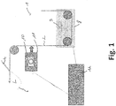
- Fig. 1 is a formed according to the concept of the invention device 1 for performing a Beklamungsvons invention for trimming a two-sided in a running direction L driven band-shaped, unwound from a roll, not shown, flexible sheet 2, here a plastic laminate shown.
- the images arranged one behind the other in the running direction may vary the print image and, in extreme cases, may share only one specific pattern (image feature) which is the basis for the image position recognition, the patterns being related in the running direction or in the running direction spaced apart from each other.
- the apparatus 1 comprises two trimming blades 4 spaced apart perpendicular to the running direction L, which are arranged stationary during the process in the specific exemplary embodiment and with which the flat material 2 is guided along two trim edges 5 determined by the trimming blade distance (cf. Fig. 3 ) is trimmed, whereby on each longitudinal side of a waste strip 6 is formed, each comprising an (original) outer edge 7 (longitudinal edge). How out Fig. 3 it can be seen, the device 1 is used to a position here to keep a distance A of the print image 3 perpendicular to the direction L to the trim edges 5 and thus to the Bekladungsmesserpositionen constant.
- a sheet alignment means 8 In the running direction L in front of the trimming knives 4 are known per se alignment means 8 (here a sheet alignment means) arranged, which is about a pivot axis 9 by means of a drive, not shown in dependence a control signal generated by control means 12 are rotatable to actively the sheet 2 (substrate strip) along a in Fig. 3 Aligned axis S perpendicular to the stationary positioned trimming blades 4 align.
- image acquisition means 10 In the running direction L between the alignment means 8 and the trimming knives 4 are image acquisition means 10, for example arranged in the form of a digital camera, which form part of print image position sensor means 11. These are signal-conducting connected to control means 12 (logic means) which generate on the basis of a printing image position of the sheet along the axis S characteristic of the print image position sensor means generated sensor signal control signal as part of a position control of the sheet 2, with which the alignment means 8 are driven.
- control is, as mentioned, such that the position of the printed image 3, in the specific embodiment, a side clearance A to the trimming blades 4 and thus to the trimming edges 5 is kept constant.
- the distances A on both longitudinal sides can be different or predetermined and, as explained in the general description part can also at least one, preferably only one, the distances zero or negative - it is essentially the position of the print image to the trimming blades 4 to constant hold.
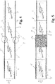
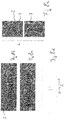
- FIGS. 4 to 6 The problem underlying the invention is based on the FIGS. 4 to 6 clear.
- a section for the production of four packaging tubes is shown. It can be seen that at an offset position 13, the relative position of the print image 3 to the (original) outer edges 7 varies.
- the relative position between the flat material 2 and the trim edges 5 has to be adjusted in order to keep the position of the printed image 3 constant relative to the trim edges. This then causes the position of the outer edges 7 to the trim edges 5 along the axis S changed.
- the offset position 13 is covered by an adhesive strip 14, as this usually results in the so-called. Splicing of different flat material rolls derived flat material webs.
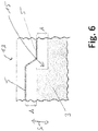
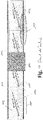
- Fig. 6 shows the offset region 13 in an enlarged view. Evident is the offset 15 in print image 3 and the course of the trim edge 5 relative to the print image 3, so that the distance A along the axis S is kept constant.
- Fig. 2 is one compared to Fig. 1 shown alternative, preferred embodiment of a device for trimming flat material 2 in the context of a tube manufacturing process.
- Fig. 1 shown alternative, preferred embodiment of a device for trimming flat material 2 in the context of a tube manufacturing process.
- the following is essentially based on the differences from the exemplary embodiment Fig. 1 having regard to the similarities Fig. 1 with associated description.
- edge sensor 16 is arranged, with which the position of an outer edge 7 of the sheet along the axis S, ie perpendicular to the direction L can be detected.
- the sensor signals of the sensors 11 and 16 are linked as part of a cascade control, such that the sensor signal of the print image position sensor means 11 of the setpoint specification for the edge sensor is used, so that the alignment means 8 are driven as a result based on both sensor signals.
- a device 1 in view of the concrete configuration of the image acquisition means 10 and the print image position sensor means 11 in both embodiments, there is a device 1 according to the Fig. 1 and 2 different possibilities.
- a two-dimensional correlation method such as a cross-correlation method
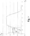
- the detection means can comprise a camera or an alternative, more cost-effective, in particular UV-light-sensitive optical sensor. If, for example, a line-shaped image feature of the, in particular continuous, pattern in the transverse direction to the running direction L, ie along the axis S sweeps over the image capture means, a curve is formed, as shown by way of example in FIG Fig. 7 illustrated.
- the X axis represents the position of the image capture means (optical sensor) to the pattern perpendicular to the direction of travel and the Y axis the intensity of the sensor signal.
- the relative distance between the image acquisition means (sensor) and the pattern of the printed image (strip) can be regulated at an operating point 18.
- Fig. 8a is explained below, the operation of a color and / or contrast analysis performing print image position sensor means.
- the position determination is preferably carried out on the basis of a visible print image section.
- FIG. 8b A magnification of a section of such an image of the print image 3 is in Fig. 8b shown.
- the image capture means capture line by line the print image, whereby blurring contrasts in the direction of L (see. Fig. 8c ), not however perpendicular to this along the S-axis a color and contrast analysis along the S-axis with appropriate quantization then finds only relevant in Fig. 8d shown edges, in the concrete embodiment, components or side edges of the letter "P" with the highest color contrast between fill color and background color.
- the location of one of the resulting contrast edges along the S-axis corresponds to the (total) print image position along the S-axis and can be used to control the sheet position along the S-axis.
Abstract
Die Erfindung betrifft ein Verfahren zum beidseitigen Besäumen eines in einer Laufrichtung (L) angetriebenen, mit einem Druckbild (3) bedruckten flexiblen Flachmaterials, insbesondere Laminatmaterials, entlang von zwei sich in der Laufrichtung (L) erstreckenden und senkrecht zur Laufrichtung (L) beabstandeten Trimmkanten (5) mittels zweier Besäumungsmesser (4), insbesondere in der Laufrichtung vor Umformmitteln zum Umformen des Flachmaterials zu einer Rohrform sowie vor Schweißmitteln zum, bevorzugt überlappenden, Verschweißen der Rohrform im Bereich der Trimmkanten (5) im Rahmen eines Verpackungstubenherstellprozesses, wobei das Flachmaterial, insbesondere in einem Bereich in der Laufrichtung (L) vor den Besäumungsmessern (4), senkrecht zur Laufrichtung (L) mittels Ausrichtemitteln (8) relativ zu den Besäumungsmessern (4) ausgerichtet wird, die mit einem von Regelmitteln (12) generierten Steuersignal angesteuert werden. Erfindungsgemäß ist vorgesehen, dass die Regelmittel (12) das Steuersignal auf Basis eines Sensorsignals von eine Druckbildposition des Druckbildes (3) senkrecht zur Laufrichtung (L) erfassenden, Bilderfassungsmittel (10) aufweisenden Druckbildpositionssensormitteln (11) erzeugen und die Ausrichtemittel (8) das Flachmaterial so relativ zu den Besäumungsmessern (4) ausrichten, dass eine Trimmkantenposition relativ zu dem Druckbild (3) konstant gehalten wird.The invention relates to a method for double-sided trimming of a in one direction (L) driven with a printed image (3) printed flexible sheet material, in particular laminate material, along two in the running direction (L) extending and perpendicular to the running direction (L) spaced trimming edges (5) by means of two trimming knives (4), in particular in the running direction before forming means for forming the flat material into a tube shape and before welding means for, preferably overlapping, welding of the tubular shape in the region of the trim edges (5) in the context of a Verpackungsstubenherstellprozesses, wherein the flat material, in particular in an area in the running direction (L) before the trimming knives (4), perpendicular to the running direction (L) by means of alignment means (8) is aligned relative to the Besäumungsmessern (4), which are controlled by a control means (12) generated control signal , According to the invention, the control means (12) generate the control signal based on a sensor signal from a print image position of the print image (3) perpendicular to the running direction (L), image capture means (10) comprising print image position sensor means (11) and the alignment means (8) the flat material align relative to the trimmers (4) so that a trim edge position relative to the print image (3) is kept constant.
Description
Die Erfindung betrifft ein Verfahren gemäß dem Oberbegriff des Anspruchs 1 zum beidseitigen (längsseitigen) Besäumen (Trimmen) eines in einer Laufrichtung angetriebenen, mit einem Druckbild, bevorzugt zusammengesetzt aus in der Laufrichtung hintereinander angeordneten, beispielsweise sich in der Laufrichtung wiederholenden oder unterschiedlichen Bildern, bedruckten, flexiblen, insbesondere bandförmigen, bevorzugt von einer Rolle abgewickelten, Flachmaterials, insbesondere eines Laminatmaterials, entlang von zwei sich in der Laufrichtung erstreckenden und senkrecht zur Laufrichtung beabstandeten Trimmkanten (Besäumungskanten) mittels zweier Besäumungsmesser (Trimmmesser), insbesondere in der Laufrichtung vor Umformmitteln zum Umformen des Materials zu einer Rohrform sowie in Laufrichtung vor, insbesondere in der Laufrichtung den Umformmitteln nachgeordneten, Schweißmitteln zum, bevorzugt überlappenden, Verschweißen der Rohrform im Bereich der Trimmkanten im Rahmen eines Verpackungstubenherstellungsprozesses, wobei das Flachmaterial, insbesondere in einem Bereich in der Laufrichtung vor dem Besäumungsmessern, senkrecht zur Laufrichtung mittels Ausrichtemitteln relativ zu den Besäumungsmessern ausgerichtet wird, die mit einem von Regelmitteln generierten Steuersignal angesteuert werden.The invention relates to a method according to the preamble of
Ferner betrifft die Erfindung eine Vorrichtung gemäß dem Oberbegriff des Anspruchs 11, die zur Durchführung des Besäumungsverfahrens ausgebildet und bestimmt ist.Furthermore, the invention relates to a device according to the preamble of
Im Rahmen der Herstellung von Verpackungstuben aus mindestens eine Kunststoffschicht aufweisendem bahnförmigen Flachmaterial, insbesondere einem Laminat ist es bekannt, das Flachmaterial vor dem Umformen zu einer Rohrform und einem Verschweißschritt zur Fixierung der Rohrform zu besäumen, also die (ursprünglichen) Laminatkanten (Außenkanten) abzutrennen. Dieser Besäumschritt ist notwendig, da die Oberfläche der Laminatkanten verschmutzt sein kann, was negative Einflüsse auf die Prozesssicherheit beim nachfolgenden Schweißprozess hat. Darüber hinaus wäre im weiteren Verfahren eine Kontamination des Tubeninneren möglich. Auch sind die Laminatkanten häufig aufgrund mechanischer Einflüsse im Rahmen des Transportes (Reibung) und der Lagerung beschädigt, wodurch die Schweißqualität weiter beeinträchtigt werden kann.In the context of the production of packaging tubes from at least one plastic layer exhibiting sheet-like flat material, in particular a laminate, it is known to trim the sheet prior to forming into a tube shape and a welding step for fixing the tube shape, ie the (original) laminate edges (outer edges) to separate. This trimming step is necessary because the surface of the laminate edges gets dirty which has negative influences on the process reliability during the subsequent welding process. In addition, a contamination of the tube interior would be possible in the further process. Also, the laminate edges are often damaged due to mechanical influences in the context of transport (friction) and storage, whereby the welding quality can be further affected.
In
Die Nachteile der bekannten Vorrichtung werden im Folgenden anhand von
Solange ein relativ breiter, unbedruckter Bereich des Flachmaterials im Bereich einer im weiteren Verlauf der Tubenherstellung zu erzeugten Längsschweißnaht zugelassen ist, sind die Druckbildschwankungen unproblematisch. Ein derartiger unbedruckter Bereich wird jedoch zunehmend als ästhetisch störend empfunden, woraus wachsende Anforderungen an die Druckpositionierung entstehen, die jedoch nicht vollständig erfüllbar sind.As long as a relatively wide, unprinted area of the flat material is permitted in the region of a longitudinal weld produced in the further course of tube production, the fluctuations in the printed image are unproblematic. However, such an unprinted area is increasingly perceived as aesthetically disturbing, resulting in growing demands on the print positioning, but they are not completely satisfiable.
Ausgehend von dem vorgenannten Stand der Technik liegt der Erfindung die Aufgabe zugrunde, das Besäumen des Flachmaterials, insbesondere im Rahmen der Tubenherstellung vor einem späteren Verschweißprozess im Hinblick auf die Lage der Trimmkanten relativ zum Druckbild zu verbessern - insbesondere soll ein (ungewolltes) Hineinschneiden in das Druckbild im Bereich einer bei dem Schweißprozess unteren bzw. inneren Trimmkante vermieden werden.Based on the aforementioned prior art, the present invention seeks to improve the trimming of the sheet, in particular in the context of tube manufacturing before a subsequent Verschweißprozess in view of the position of the trim edges relative to the printed image - in particular, an (unwanted) cutting into the Print image can be avoided in the region of a lower or inner trim edge in the welding process.
Diese Aufgabe wird mit einem Verfahren mit den Merkmalen des Anspruchs 1 gelöst, d.h. bei einem gattungsgemäßen Besäumungsverfahren dadurch, dass die Regelmittel das Steuersignal auf Basis eines Sensorsignals von einer Druckbildposition des Druckbildes senkrecht zur Laufrichtung erfassenden, Bilderfassungsmittel aufweisenden Druckbildpositionssensormittel erzeugen und die Ausrichtemittel das, bevorzugt bandförmige, Flachmaterial so (senkrecht zur Laufrichtung und senkrecht zur Materialstärkerichtung des Flachmaterials) relativ zu dem Besäumungsmessern ausrichten, dass eine Trimmkantenposition relativ zu dem Druckbild konstant gehalten wird.This object is achieved by a method with the features of
Hinsichtlich der Besäumungsvorrichtung wird die Aufgabe mit den Merkmalen des Anspruchs 11 gelöst.With regard to the trimming device, the object is achieved with the features of
Vorteilhafte Weiterbildungen der Erfindung sind in den Unteransprüchen angegeben. In den Rahmen der Erfindung fallen sämtliche Kombinationen aus zumindest zwei von der Beschreibung, den Ansprüchen und/oder den Figuren offenbarten Merkmalen.Advantageous developments of the invention are specified in the subclaims. All combinations of at least two features disclosed by the description, the claims and / or the figures fall within the scope of the invention.
Zur Vermeidung von Wiederholungen sollen verfahrensgemäß offenbarte Merkmale auch als vorrichtungsgemäß offenbart gelten und beanspruchbar sein. Ebenso sollen vorrichtungsgemäß offenbarte Merkmale als verfahrensgemäß offenbart gelten und beanspruchbar sein.In order to avoid repetition, features disclosed according to the method are also to be regarded as disclosed in accordance with the device and to be able to be claimed. Likewise, devices disclosed according to the device should be regarded as disclosed according to the method and be able to be claimed.
Der Erfindung liegt der Gedanke zugrunde, das Flachmaterial senkrecht zu dessen Laufrichtung relativ zu den Besäumungsmessern auf Basis einer Positionsbestimmung des Druckbildes des Flachmaterials, d.h. auf Basis einer Druckbildposition auszurichten, wobei die Regelung der Ausrichtemittel zur Variation der Relativposition zwischen dem Flachmaterial und den Besäumungsmessern so durchgeführt wird, dass die Besäumungsmesser und damit die Trimmkantenposition relativ zu dem Druckbild konstant gehalten wird. Anders ausgedrückt ist erfindungsgemäß im Rahmen des Verfahrens und der Vorrichtung vorgesehen, den Regelmitteln Bilderfassungsmittel zur abschnittsweisen oder vollständigen Erfassung des Druckbildes, insbesondere eines sich in der Laufrichtung fortsetzend oder wiederholenden Bildmerkmals (Musters), aufweisende Druckbildpositionssensormittel zuzuordnen, derart, dass ein Druckbildposition kennzeichnendes Sensorsignal der Druckbildpositionssensormittel in die Generierung des Steuersignals für die Ausrichtemittel einfließt oder davon gebildet wird, um das Flachbandmaterial anhand der Druckbildposition des Druckbildes senkrecht zur Laufrichtung relativ zu den Besäumungsmessern auszurichten. In die Bestimmung der Regelabweichung von einer Sollposition des Flachmaterials relativ zu den Besäumungsmessern fließt also erfindungsgemäß eine von dem Druckbildpositionsmitteln ermittelte Druckbildposition (senkrecht zur Laufrichtung) bzw. ein mit der Druckbildposition korrespondierendes Sensorsignal der Druckbildpositionsmittel ein. Bevorzugt wird dabei ein Abstand des Druckbildes senkrecht zur Laufrichtung zu zumindest einer der Trimmkanten auf einen Wert größer Null gehalten, sodass nach dem Besäumen (Schneiden, Trimmen) ein unbedruckter Randbereich neben dem Druckbild bestehen bleibt. Denkbar ist es jedoch auch, den vorgenannten Abstand auf Null einzustellen oder auch bei speziellen Anwendungen, zumindest für eine bei dem bevorzugt nachfolgenden Längsnahtschweißprozess oben bzw. außen liegen kommende Flachmaterialtrimmkante sogar negativ - dies bedeutet, dass für spezielle Anwendungen bei einer oberen Trimmkante bewusst ein vorgegebenes bzw. definiertes Maß in das Druckbild (bedruckter Bereich) hineingeschnitten wird.The invention is based on the idea of aligning the flat material perpendicular to its direction of travel relative to the trimming knives on the basis of a position determination of the printed image of the flat material, ie on the basis of a printed image position, the regulation of the aligning means for varying the relative position between the flat material and the trimming knives being carried out in this way is that the trimmings and thus the trim edge position is kept constant relative to the printed image. In other words, according to the invention, within the scope of the method and the device, it is provided to associate the control means with image acquisition means for partially or completely capturing the print image, in particular a print image position sensor means having a continuous or repeating image feature (pattern), such that a sensor signal characterizing print image position Print image position sensor means is incorporated in the generation of the control signal for the alignment means or is formed thereof to align the ribbon material based on the print image position of the printed image perpendicular to the direction relative to the trimming blades. In the determination of the control deviation from a target position According to the invention, the flat material relative to the trimming blades thus flows according to the invention a printed image position (perpendicular to the direction of travel) determined by the print image position means or a sensor signal of the print image position means corresponding to the print image position. In this case, a distance of the printed image perpendicular to the running direction to at least one of the trim edges is preferably kept at a value greater than zero, so that after trimming (cutting, trimming) an unprinted edge region remains adjacent to the printed image. However, it is also conceivable to set the above-mentioned distance to zero or even in special applications, at least for a preferably following longitudinal seam welding process up or outside coming flat material trim edge even negative - this means that for specific applications with an upper trim edge deliberately a predetermined or defined dimension is cut into the printed image (printed area).
Das erfindungsgemäße Verfahren und die erfindungsgemäße Vorrichtung kompensieren somit Druckbildpositionsschwankungen relativ zu den Trimmkanten und damit relativ zur Längsschweißnaht einer Tube senkrecht zur Laufrichtung, wodurch aus dem Besäumungsverfahren, insbesondere für den erwähnten, nachfolgenden Schweißprozess ein in der Laufrichtung gleichbleibend zwischen den Trimmkanten angeordnetes Druckbild resultiert.The method according to the invention and the device according to the invention thus compensate printing image position fluctuations relative to the trim edges and thus relative to the longitudinal weld of a tube perpendicular to the direction of travel, resulting in a printing image arranged uniformly between the trim edges in the running direction from the trimming method, in particular for the abovementioned subsequent welding process.
Ein gleichbleibend zwischen den Trimmkanten angeordnetes Druckbild ist von ganz besonderem Vorteil für eine bevorzugte Ausführung des erfindungsgemäßen Verfahrens und der erfindungsgemäßen Vorrichtung, bei der die Trimm- bzw. Besäumungskanten nicht in einer Auf-Stoß-Anordnung miteinander verschweißt werden, sondern in einer überlappenden Anordnung, also derart, dass das Flachmaterial im Bereich seiner Längs- bzw. Trimmkanten überlappend angeordnet ist bzw. wird und die Längs- bzw. Trimmkanten in dieser überlappenden Position miteinander verschweißt werden. Bei einem derartigen überlappenden Verschweißen wirken sich Druckbildpositionsschwankungen besonders stark auf das ästhetische Erscheinungsbild sowie auf die Qualität des Schweißprozesses als solches aus. Bevorzugt sind daher die Umformmittel und die Schweißmittel derart ausgebildet, dass mittels der Umformmittel eine überlappende Anordnung der Trimmkanten, also eine radial benachbarte Positionierung bewirkt und die Rohrform in dieser überlappenden Anordnung verschweißbar wird bzw. verschweißt ist. Die Erfindung ist jedoch nicht auf diese bevorzugte Ausführungsform beschränkt - grundsätzlich möglich bzw. realisierbar ist auch eine alternative Anordnung der Trimmkanten auf Stoß und ein Verschweißen der Trimmkanten in dieser Position.A printed image arranged uniformly between the trim edges is of very particular advantage for a preferred embodiment of the method according to the invention and of the device according to the invention, in which the trimming or trimming edges are not welded together in an on-off arrangement, but in an overlapping arrangement. in other words such that the flat material is or are overlapped in the region of its longitudinal or trim edges and the longitudinal or trim edges are welded together in this overlapping position. In such overlapping welding, print image position variations have a strong impact on the aesthetic appearance as well as the quality of the welding process as such. Preference is therefore given to the forming and the welding means are formed in such a way that an overlapping arrangement of the trim edges, ie a radially adjacent positioning, is effected by means of the forming means and the tubular shape is welded or welded in this overlapping arrangement. However, the invention is not limited to this preferred embodiment - in principle possible or feasible is also an alternative arrangement of the trim edges on impact and welding the trim edges in this position.
Unabhängig von der konkreten Ausgestaltung bzw. Anordnung der Trimmkanten auf Stoß oder überlappend ist es von Vorteil, wenn die Regelmittel die Trimmkantenposition relativ zu dem Druckbild so konstant halten, dass Abstandsschwankungen zwischen dem Druckbild und einer Trimmkantenposition maximal 0,3mm betragen, wobei bevorzugt die maximale Abstandsschwankung in einem Wertebereich zwischen 0,1 mm (oder geringer) und 2,5mm liegt. Eine bevorzugte Maximalabstandstoleranz beträgt 0,15mm.Regardless of the specific configuration or arrangement of the trim edges on impact or overlapping, it is advantageous if the control means keep the trim edge position relative to the printed image so constant that distance variations between the printed image and a trim edge position maximum 0,3mm, preferably the maximum Distance variation is in a range between 0.1 mm (or less) and 2.5 mm. A preferred maximum clearance tolerance is 0.15mm.
Wie eingangs erwähnt, besteht das Druckbild im Regelfall aus sich in der Laufrichtung wiederholenden, identischen Bildern - hierauf ist die Erfindung jedoch ausdrücklich nicht beschränkt, da es insbesondere mit modernen Digitaldruckverfahren möglich ist, unterschiedliche Bilder in der Laufrichtung hintereinander anzuordnen bzw. zu drucken, sodass es nicht zwingend ist, dass die hintereinander angeordneten Bilder periodisch bzw. identisch sind - wesentlich ist es lediglich, dass ein Merkmal der Bilder periodisch ist, d.h. sich von Bild zu Bild wiederholt und die Position dieses Bildmerkmals (Musters) mithilfe der Druckbildpositionssensormittel erfassbar ist. Theoretisch ist es sogar denkbar, dass sich sämtliche, aufeinanderfolgende Bilder des Druckbildes unterscheiden, um somit individuell ausgestaltete Tuben, also Unikate herzustellen.As mentioned at the outset, the printed image as a rule consists of identical images repeating in the direction of travel. However, the invention is expressly not limited to this, since it is possible, particularly with modern digital printing processes, to arrange or print different images one behind the other in the direction of travel it is not mandatory that the successively arranged images are periodic or identical - it is only essential that a feature of the images is periodic, ie is repeated from image to image and the position of this image feature (pattern) is detectable using the print image position sensor means. Theoretically, it is even conceivable that all the successive images of the printed image differ in order to produce individually designed tubes, ie unique pieces.
Im Hinblick auf die konkrete Ausgestaltung der Ausrichtemittel zur Relativpositionierung des Flachmaterials zu den Besäumungsmessern bzw. den Trimmkanten gibt es unterschiedliche Möglichkeiten. Grundsätzlich ist es möglich, aktiv die Besäumungsmesser senkrecht zur Laufrichtung des Laminates zu verstellen. Bevorzugt ist jedoch eine Ausführungsform mit feststehenden Besäumungsmessern und einer aktiven Verstellung des Flachmaterials. Bei einer solchen Ausführungsform sind die Ausrichtemittel bevorzugt in der Laufrichtung des Laminates vor den Besäumungsmessern angeordnet, wobei es weiter bevorzugt ist, in der Laufrichtung zwischen den Ausrichtemitteln und den Besäumungsmessern die Bilderfassungsmittel der Druckbildpositionssensormittel anzuordnen. Die feste Anordnung der Besäumungsmesser hat den Vorteil, dass das Flachmaterial nach dem Besäumungsprozess für die weiteren Prozessschritte schon vorpositioniert ist, d.h. immer in derselben Position senkrecht zur Laufrichtung verbleibt bzw. angeordnet ist, woraus eine höhere Prozesssicherheit resultiert.With regard to the specific embodiment of the alignment means for relative positioning of the sheet material to the trimming knives or the trim edges, there are different possibilities. In principle, it is possible to actively adjust the trimming blades perpendicular to the running direction of the laminate. However, an embodiment with fixed trimmers is preferred and an active adjustment of the sheet. In such an embodiment, the alignment means are preferably arranged in front of the trimmers in the direction of travel of the laminate, and it is further preferred to arrange the image-sensing means of the print-image position sensor means in the running direction between the alignment means and the trimmers. The fixed arrangement of the trimming blades has the advantage that the flat material is already prepositioned after the trimming process for the further process steps, ie always remains or is arranged in the same position perpendicular to the running direction, resulting in a higher process reliability.
Die Ausrichtemittel umfassen bevorzugt zwei relativ fest zueinander positionierte, in Laufrichtung beabstandete Rollen, die um parallel zum Flachmaterial ausgerichtete Rollenachsen rotieren. Die Rollen sind zur Positionsveränderung bzw. Ausrichtung des Flachmaterials senkrecht zur Laufrichtung bevorzugt um eine winklig, insbesondere senkrecht zur Flächenerstreckung des Flachmaterials und der Rollenachsen orientierte Schwenkachse mittels eines Antriebs verschwenkbar, der mit dem Steuersignal der Regelmittel angesteuert wird.The alignment means preferably comprise two relatively fixedly positioned, in the direction of spaced rollers which rotate about aligned parallel to the sheet material roller axes. The rollers are for the change in position or orientation of the sheet perpendicular to the direction preferably by an angle, in particular perpendicular to the surface extension of the sheet and the roller axes oriented pivot axis by means of a drive which is controlled by the control signal of the control means.
Auch im Hinblick auf die Ausbildung und Anordnung der Besäumungsmesser gibt es unterschiedliche Möglichkeiten. So kann eine oder können beide Trimmkanten senkrecht zur Flächenerstreckung des Flachmaterials verlaufen - bevorzugt ist jedoch eine alternative Ausführungsform, bei der die Besäumungsmesser derart ausgebildet und angeordnet sind, dass zumindest eine der Trimmkanten schräg zur Flächenerstreckung des Flachmaterial verläuft/verlaufen.There are also various possibilities with regard to the design and arrangement of the trimming blades. Thus, one or both trim edges may extend perpendicular to the surface extension of the flat material - however, an alternative embodiment is preferred, in which the trimming blades are designed and arranged such that at least one of the trim edges runs obliquely to the surface extension of the flat material.
Ganz besonders bevorzugt ist es, wenn die Bilderfassungsmittel von einer Kamera gebildet sind. Es können jedoch alternative, einfacher aufgebaute, insbesondere optische Sensoren eingesetzt werden, beispielsweise zur Erfassung später noch zu erläuternder, ausschließlich unter UV-Licht sichtbaren und/oder für das menschliche Auge sichtbares Muster des Druckbildes.It is very particularly preferred if the image capture means are formed by a camera. However, alternative, more simply designed, in particular optical, sensors can be used, for example for detecting the pattern of the printed image which is still to be explained later and which is visible only under UV light and / or visible to the human eye.
Grundsätzlich ist es möglich, mittels der Bilderfassungsmittel das gesamte Druckbild senkrecht zur Laufrichtung sowie in Laufrichtung zu erfassen. Insbesondere, jedoch nicht beschränkt hierauf ist es, im Rahmen einer später noch zu erläuternden Kaskadenregelung möglich in der Laufrichtung nur abschnittsweise das Druckbild zu erfassen. Zusätzlich oder alternativ ist es zur Vereinfachung der Auswertung möglich, das Druckbild senkrecht zur Laufrichtung nur ausschnittsweise zu erfassen, insbesondere im Rahmen der später noch zu erläuternden möglichen Detektierung eines UV-Licht reflektierenden Musters und/oder im Rahmen einer Kontrast- und/oder Farbanalyse insbesondere eines sichtbaren Musters, zum Auffinden eines mit der Druckbildposition korrelierenden Farb- und/oder Kontrastsprungs im Druckbild senkrecht zu Laufrichtung.In principle, it is possible to capture the entire print image perpendicular to the running direction as well as in the running direction by means of the image capturing means. In particular, but not limited to this, it is only possible to capture the printed image in sections in the direction of travel within the scope of a cascade control to be explained later. Additionally or alternatively, to simplify the evaluation, it is possible to capture the print image only in sections perpendicular to the direction of travel, in particular during the possible detection of a UV-light reflecting pattern and / or as part of a contrast and / or color analysis in particular a visible pattern, for finding a correlated with the print image position color and / or contrast jump in the print image perpendicular to the direction.
Im Hinblick auf die konkrete Umsetzung/Realisierung der Druckbild-Positionsbestimmung und damit der Druckbildpositionssensormittel und deren Bilderfassungsmittel gibt es im Folgenden noch im Detail erläuterte unterschiedliche Ausführungsmöglichkeiten, beispielsweise im Wege eines, bevorzugt zweidimensionalen, Korrelationsverfahrens, beispielsweise eines Kreuzkorrelationsverfahrens, und/oder eines Mustervergleichs und/oder einer Positionserkennung eines, insbesondere für den Menschen nicht sichtbaren, UV-reflektierenden Musters, insbesondere einer Musterkante, bevorzugt einer sich in Laufrichtung erstreckenden Kante, und/oder einer ganz besonders bevorzugten Kontrast- und/oder Farbwechselanalyse des Druckbildes, insbesondere eines Abschnittes des Druckbildes.With regard to the concrete implementation / realization of the print image position determination and thus the print image position sensor means and their image capture means, there are explained below in detail explained different execution options, for example by way of a preferably two-dimensional correlation method, for example, a cross-correlation method, and / or a pattern comparison and or a position detection of a, in particular for human invisible, UV-reflective pattern, in particular a pattern edge, preferably extending in the direction of edge, and / or a very particularly preferred contrast and / or color change analysis of the printed image, in particular a portion of print image.
So weisen die erfindungsgemäßen Druckbildpositionssensormittel in besonders bevorzugter Weise Mustererkennungsmittel auf, welche ausgebildet sind, in einem gegebenen Bild - nämlich etwa einer erfassten Abbildung des Druckbildes - ein vorgegebenes Muster zu erkennen und zu lokalisieren. Derartige, als allgemein bekannt vorausgesetzte Technologien werden auch als "Pattern Matching" (PM) bekannt.Thus, the print image position sensor means according to the invention particularly preferably have pattern recognition means which are designed to recognize and locate a given pattern in a given image, namely a captured image of the print image. Such technologies, which are generally known, are also known as pattern matching (PM).
Eine solche Technologie, welche geeignet programmierte Datenverarbeitungsmittel einsetzt, ist damit in der Lage, ein einer Sollposition bzw. einem Sollbild (insbesondere ausschnitthaft) entsprechendes Muster im aktuellen Druckbild aufzufinden und zu lokalisieren, etwa der Gestalt, dass als Ergebnis einer derartigen erfindungsgemäß die Druckbildpositionssensormittel weiterbildenden Technologie ein (ein- oder zweidimensionaler) Ortsvektor erzeugt wird und dann der nachfolgenden Verarbeitung durch die Ausrichtemittel zur Verfügung steht, welcher eine Position bzw. Positionsverschiebung zwischen dem (aktuellen) Druckbild und dem (bevorzugt ausschnitthaft vorliegenden) Referenzbild wiedergibt bzw. entspricht.Such a technology, which uses suitably programmed data processing means, is thus capable of a desired position or a target image (in particular section-wise) to locate and localize a corresponding pattern in the current print image, such as the shape that a (one-dimensional or two-dimensional) position vector is generated as a result of such a technology developing the print image position sensor means according to the invention and is then available for subsequent processing by the alignment means, which represents or corresponds to a position or positional shift between the (current) printed image and the (preferably in sections) reference image.
Als günstige Vorgehensweise zur Realisierung einer solchen Technologie können Verfahren der Korrelation in der (digitalen) Bildverarbeitung gelten, wobei insbesondere die sogenannte normierte Kreuzkorrelation (als Variante zu Methoden der quadratischen Abstände bzw. des sog. maximalen Differenzbetrages) im vorliegenden Anwendungsgebiet besonders gute Ergebnisse liefert: Insbesondere eine Normierung von Korrelationswerten verringert die Empfindlichkeit einer Korrelationsermittlung gegenüber (starken) Kontrasten bzw. Intensitätsänderungen im Druckbild, und der der vorliegenden Erfindung zugrundeliegende Problemkontext - zweidimensional - flächige Variation und Größenskalierung oder Rotation eines Musters machen korrelationsbasierte Mustererkennungstechnologien besonders geeignet.As a favorable procedure for the realization of such a technology, methods of correlation in (digital) image processing may apply, in particular the so-called normalized cross-correlation (as a variant of methods of quadratic distances or the so-called maximum difference) in the present field of application yields particularly good results: In particular, a normalization of correlation values reduces the sensitivity of a correlation determination against (strong) contrasts or intensity changes in the printed image, and the problem context underlying the present invention - two-dimensional - surface variation and size scaling or rotation of a pattern make correlation-based pattern recognition technologies particularly suitable.
Entsprechend ist es zusätzlich weiterbildend bevorzugt, das Steuersignal auf der Basis einer Korrelation, weiter bevorzugt einer (normierten) Kreuzkorrelation zwischen einer aktuellen Abbildung des Druckbildes und einem weiter bevorzugt ausschnitthaft als etwa im Hinblick auf Eigentümlichkeit bzw. Erkennbarkeit besonders geeignetem und in einer Sollposition vorliegenden Ausschnitt aus dem Druckbild ermitteln, wobei Ergebnis einer solchen Korrelationsermittlung dann insbesondere auch Vektor- bzw. Abstandsinformationen sind, wie das (aktuelle) Druckbild relativ zur Referenz positioniert ist. Entsprechend erlauben diese Vektor- bzw. Abstandsdaten dann das erfindungsgemäße Ausrichten durch die Ausrichtemittel.Accordingly, it is additionally preferred to further develop the control signal on the basis of a correlation, more preferably a (normalized) cross-correlation between a current image of the print image and a detail section that is particularly well suited for peculiarity or recognizability and is present in a desired position determine the result of such a correlation determination in particular vector or distance information, as the (current) print image is positioned relative to the reference. Accordingly, this vector or distance data then allow the alignment according to the invention by the alignment means.
Alternative und, etwa im Hinblick auf Geschwindigkeit und Rechenleistung potentiell der beschriebenen Korrelation teilweise überlegene Technologien zum Bildvergleich zwischen einer (aktuellen) Abbildung des Druckbildes und einer Bildreferenz können etwa Kontrast- und/oder Farbwechselanalysen sein. Zu diesem Zweck wird in ansonsten bekannter Weise eine der Abbildung entsprechende Bildfunktion in ihren Extremwerten bzw. Wendepunkten untersucht, um festzustellen, an welchen Positionen, in welche Richtung und mit welcher Stärke etwa ein Farbwechsel im Bildsignal vorliegt. Derartige, auch als Bildkantendetektion bezeichnete Technologien ermöglichen dann, mit geeigneter nachgeschalteter Filterung, die Identifikation relevanter Bildregionen bzw., entsprechend der oben skizzierten Vorgehensweise, ein Feststellen einer Übereinstimmung bzw. eine Lokalisierung etwaiger Verschiebungen zwischen übereinstimmenden Bereichen.Alternative and, for example with regard to speed and computing power potentially of the described correlation, partially superior technologies for image comparison between a (current) image of the print image and an image reference can be contrast and / or color change analyzes. For this purpose, an image function corresponding to the image in its extreme values or inflection points is examined in an otherwise known manner in order to determine at which positions, in which direction and with which intensity there is a color change in the image signal. Such technologies, also referred to as image edge detection, then enable, with suitable downstream filtering, the identification of relevant image regions or, according to the procedure outlined above, a determination of a match or a localization of any shifts between matching regions.
Besonders zweckmäßig ist es, wenn die Bilderfassungsmittel Bildpunkte entlang einer sich winklig, insbesondere senkrecht zur Laufrichtung erstreckenden Zeile, ganz besonders bevorzugt entlang mehrerer paralleler Zeilen erfassen ganz besonders zweckmäßig hat es sich erwiesen, wenn die Bilderfassungsmittel in Form einer (Digital-)Kamera, insbesondere einer CCD-Kamera realisiert sind.It is especially expedient if the image acquisition means detect pixels along a line which extends at an angle, in particular perpendicularly to the running direction, very particularly preferably along several parallel lines. It is particularly expedient if the image acquisition means in the form of a (digital) camera, in particular a CCD camera are realized.
Als besonders zweckmäßig hat es sich herausgestellt, wenn das Steuersignal nicht nur auf Basis des Sensorsignals der Druckbildpositionssensormittel von den Regelmitteln generiert wird, sondern dass in die Erzeugung des Steuersignals ein weiteres Sensorsignal einfließt, nämlich ein Sensorsignal eines vorzugsweise zusätzlich zu den Druckbildpositionssensormitteln vorgesehenen (an sich bekannten) Kantensensors, beispielsweise in Form eines Ultraschallsensors, der die Position einer (abzutrennenden) Außenkante des Flachmaterials erfasst. Bevorzugt fließen beide Sensorsignale in eine Kaskadenregelung mit einem äußeren und einen inneren Regelkreis ein, wodurch eine kontinuierliche Flachmaterialspositionsregelung auch für den Fall ermöglicht wird, dass das Sensorsignal der Druckbildpositionssensormittel immer wieder unterbrochen und/oder nur in Bezug auf, insbesondere regelmäßig, in Laufrichtung beabstandeten Teilabschnitten des Druckbildes erzeugt wird, sei es aufgrund einer getakteten bzw. unterbrochenen Bilderfassung und/oder einer nicht in der Laufrichtung durchgehenden bzw. fortlaufenden Gestaltung des Druckbildes, beispielsweise in dem mittels der Bilderfassungsmittel die Position von wiederkehrenden, in der Laufrichtung beabstandeten Druckbildmuster bzw. -bestandteile erfasst wird. Als besonderes zweckmäßig hat es sich dabei erwiesen, wenn der Sollwert für den Kantensensor nicht wie im Stand der Technik konstant vorgegeben ist, sondern auf Basis des Sensorsignals der Druckbildpositionssensormittel variiert wird. Anders ausgedrückt umfassen die Regelmittel einen inneren Regelkreis, im Rahmen dessen die Flachmaterialposition senkrecht zur Laufbandrichtung auf Basis eines Kantensensorsignals geregelt wird, wobei im Rahmen eines die Druckbildpositionssensorsmittel umfassenden äußeren Regelkreis eine Regelvorgabe bzw. ein Sollwert der Flachmaterialposition senkrecht zur Laufrichtung für den inneren Regelkreis bestimmt wird, relativ zu dem von den Regelmitteln die durch das Steuersignal zu kompensierende Regelabweichung bestimmt wird. Bei einer solchen, besonders bevorzugten Ausführungsform fließt somit das Sensorsignal der Druckbildpositionssensormittel nicht unmittelbar, was alternativ möglich ist, in das Steuersignal ein, sondern mittelbar im Rahmen der erläuterten Kaskadenregelung. Auf diese Weise ist es möglich für die innere Regelung, insbesondere nach einer jeweiligen zuverlässigen Bildpositionserkennung genau berechnet und aktualisiert wird. Die Kaskadenregelung hat den entscheidenden Vorteil, dass der den Kantensensor umfassende innere Regelkreis typischerweise mit Signalerfassungsraten zwischen 5Hz bis 50kHz arbeitet und damit deutlich schneller reagiert, als der die Bilderfassungsmittel umfassende äußere Regelkreis, welcher typischerweise Aktualisierungsraten im Bereich zwischen 0,5Hz und 500Hz ermöglicht. Bevorzugt ist die Signalerfassungsrate des inneren Regelkreises mindestens 10mal, bevorzugt mindestens 50mal, ganz besonders bevorzugt mindestens 100mal größer bzw. schneller als die des äußeren Regelkreises.It has proven to be particularly expedient if the control signal is not only generated by the control means on the basis of the sensor signal of the print image position sensor means, but that a further sensor signal flows into the generation of the control signal, namely a sensor signal of a sensor signal (preferably provided in addition to the print image position sensor means) known) edge sensor, for example in the form of an ultrasonic sensor, which detects the position of a (to be separated) outer edge of the sheet. Preferably, both sensor signals flow in a cascade control with an outer and an inner control loop, whereby a continuous sheet position control is made possible even in the event that the sensor signal of the print image position sensor means again and again interrupted and / or spaced only in relation to, in particular regularly, in the running direction Subsections of the printed image is generated, be it due to a clocked or interrupted image acquisition and / or not continuous in the running direction or continuous design of the printed image, for example, in the means of the image sensing means the position of recurring, spaced in the direction print pattern or components is recorded. It has proved to be particularly expedient if the setpoint value for the edge sensor is not constant, as in the prior art, but is varied on the basis of the sensor signal of the print image position sensor means. In other words, the control means comprise an inner control loop, in which the flat material position is controlled perpendicular to the treadmill direction based on an edge sensor signal, wherein in the context of an outer control loop comprising the print image position sensor means, a setpoint of the flat material position is determined perpendicular to the direction for the inner loop relative to that of the control means, the control deviation to be compensated by the control signal is determined. In such a particularly preferred embodiment, therefore, the sensor signal of the print image position sensor means does not flow directly into the control signal, which is alternatively possible, but indirectly within the scope of the explained cascade control. In this way, it is possible for the inner control, especially after a respective reliable image position detection is calculated and updated accurately. The cascade control has the distinct advantage that the inner loop comprising the edge sensor typically operates at signal acquisition rates between 5Hz to 50kHz and thus reacts much faster than the outer loop comprising the image capture means, which typically provides refresh rates in the range 0.5Hz to 500Hz. The signal detection rate of the inner control loop is preferably at least 10 times, preferably at least 50 times, very particularly preferably at least 100 times greater or faster than that of the outer control loop.
Weitere Vorteile, Merkmale und Einzelheiten der Erfindung ergeben sich aus der nachfolgenden Beschreibung bevorzugter Ausführungsbeispiele sowie anhand der Zeichnungen.Further advantages, features and details of the invention will become apparent from the following description of preferred embodiments and from the drawings.
Diese zeigen in
- Fig. 1
- eine nach dem Konzept der Erfindung ausgebildete Ausführungsform einer Besäumungsvorrichtung mit Druckbildpositionssensormitteln,
- Fig. 2
- eine alternative, erfindungsgemäße Ausführungsform, bei der zusätzlich zu den Druckbildpositionssensormitteln ein Kantensensor vorgesehen ist und die Sensorsignale beider Sensoren im Rahmen einer Kaskadenregelung verknüpft sind,
- Fig. 3
- eine Draufsicht auf ein ausschnittsweise dargestelltes Flachmaterial zur Erläuterung der im Rahmen der Erfindung relevanten Begrifflichkeiten,
- Fig. 4 und 5
- zeigen eine Draufsicht auf einen Ausschnitt eines Flachmaterials mit einem Druckbild, dass aus mehreren sich in der Laufrichtung wiederholenden Bildern besteht, wobei in
Fig. 4 ein (notwendiger) Versatz von Trimmkanten gezeigt, welcher nachgeführt werden muss, wobei inFig. 5 der Versatz, wie bei normalen Produktionsbedingungen üblich, durch ein Stück Klebeband verdeckt ist, - Fig. 6
- eine vergrößerte Darstellung der Versatzsituation gemäß
Fig. 4 , - Fig. 7
- ein mögliches Sensorsignal im Rahmen der Erfassung eines kontinuierlichen, beispielsweise UV-reflektierenden Musters,
- Fig. 8a bis 8d
- Darstellungen zur Erläuterung einer möglichen Farb- und/oder Kontrastanalyse zur Positionsdetektion des Druckbildes, und
- Fig. 9
und 10 - Darstellungen zum Stand der Technik.
- Fig. 1
- an embodied according to the concept of the invention embodiment of a Besäumungsvorrichtung with print image position sensor means,
- Fig. 2
- an alternative, inventive embodiment in which in addition to the print image position sensor means an edge sensor is provided and the sensor signals of both sensors are linked in the context of a cascade control,
- Fig. 3
- a plan view of a partially illustrated sheet material for explaining the terms relevant in the context of the invention,
- 4 and 5
- show a plan view of a section of a flat material with a printed image that consists of several repeating in the running direction images, wherein
Fig. 4 shown a (necessary) offset of trim edges, which must be tracked, where inFig. 5 the offset, as usual in normal production conditions, is covered by a piece of tape, - Fig. 6
- an enlarged view of the offset situation according to
Fig. 4 . - Fig. 7
- a possible sensor signal during the detection of a continuous, for example UV-reflecting pattern,
- Fig. 8a to 8d
- Representations for explaining a possible color and / or contrast analysis for position detection of the printed image, and
- FIGS. 9 and 10
- Representations of the prior art.
In den Figuren sind gleiche Elemente und Elemente mit der gleichen Funktion mit den gleichen Bezugszeichen gekennzeichnet.In the figures, like elements and elements having the same function are denoted by the same reference numerals.
In
In der Laufrichtung L vor den Besäumungsmessern 4 sind an sich bekannte Ausrichtemittel 8 (hier eine Flachmaterial-Ausrichteeinrichtung) angeordnet, die um eine Schwenkachse 9 mittels eines nicht gezeigten Antriebs in Abhängigkeit eines von Regelmittel 12 erzeugten Steuersignals rotierbar sind, um aktiv das Flachmaterial 2 (Substratband) entlang einer in
In der Laufrichtung L zwischen den Ausrichtemitteln 8 und den Besäumungsmessern 4 sind Bilderfassungsmittel 10, beispielsweise in Form einer Digitalkamera angeordnet, die einen Bestandteil von Druckbildpositionssensormittel 11 bilden. Diese sind signalleitend mit Regelmitteln 12 (Logikmitteln) verbunden, die auf Basis eines eine Druckbildposition des Flachmaterials entlang der Achse S kennzeichnenden von den Druckbildpositionssensormitteln generiertes Sensorsignals ein Steuersignal im Rahmen einer Positionsregelung des Flachmaterials 2 erzeugen, mit welchem die Ausrichtemittel 8 angesteuert werden. Dabei erfolgt die Regelung, wie erwähnt, derart, dass die Position des Druckbildes 3, in dem konkreten Ausführungsbeispiel ein Seitenabstand A zu den Besäumungsmessern 4 und damit zu den Trimmkanten 5 konstant gehalten wird. Selbstverständlich können die Abstände A auf beiden Längsseiten unterschiedlich sein bzw. vorgegeben werden und, wie im allgemeinen Beschreibungsteil erläutert kann auch mindestens einer, bevorzugt ausschließlich einer, der Abstände Null oder negativ sein - wesentlich ist es die Position des Druckbildes zu den Besäumungsmessern 4 konstant zu halten.In the running direction L between the alignment means 8 and the trimming
Die der Erfindung zugrunde liegende Problematik wird anhand der
In
Zu erkennen ist, dass in der Laufrichtung L zwischen den Besäumungsmessern 4 und den Ausrichtemitteln 8 zusätzlich zu den Bilderfassungsmitteln 10 der Druckbildpositionssensormittel 11 ein, hier beispielsweise als Ultraschallsensor ausgebildeter, Kantensensor 16 angeordnet ist, mit welchem die Position einer Außenkante 7 des Flachmaterials entlang der Achse S, d.h. senkrecht zur Laufrichtung L detektierbar ist. In der bevorzugten Ausführungsform werden die Sensorsignale der Sensoren 11 und 16 im Rahmen einer Kaskadenregelung verknüpft, derart, dass das Sensorsignal der Druckbildpositionssensormittel 11 der Sollwertvorgabe für den Kantensensor dient, sodass im Ergebnis die Ausrichtemittel 8 auf Basis beider Sensorsignale angesteuert werden.It can be seen that in the running direction L between the trimming
Wie im allgemeinen Beschreibungsteil erläutert, gibt es im Hinblick auf die konkrete Ausgestaltung der Bilderfassungsmittel 10 und der Druckbildpositionssensormittel 11 bei beiden Ausführungsbeispielen einer Vorrichtung 1 gemäß den
Anhand der
Eine Vergrößerung eines Ausschnitts eines solchen Bildes des Druckbildes 3 ist in
- 100100
- Vorrichtungcontraption
- 101101
- Laufrichtungdirection
- 102102
- Flachmaterialflat material
- 103103
- Ausrichtemitelaligning Mitel
- 104104
- BesäumungsmesserBesäumungsmesser
- 105105
- Abfallstreifenwaste strips
- 106106
- Regelmittelcontrol means
- 107107
- SteuersignalleitungControl signal line
- 108108
- Kantensensoredge sensor
- 109109
- Druckbildprint image
- 110110
- Außenkantenouter edges
- 111111
- Spleißpositionsplicing
- 112112
- Trimmkantentrim edges
- 113113
- BereichArea
- 11
- Vorrichtungcontraption
- 22
- Flachbereichflat area
- 33
- Druckbildprint image
- 44
- BesäumungsmesserBesäumungsmesser
- 55
- Trimmkantentrim edges
- 66
- Abfallstreifenwaste strips
- 77
- Außenkanteouter edge
- 88th
- Ausrichtemittelalignment means
- 99
- Schwenkachseswivel axis
- 1010
- Bilderfassungsmittel (optischer Sensor)Image capture device (optical sensor)
- 1111
- DruckbildpositionssensormittelPrint image position sensor means
- 1212
- Regelmittelcontrol means
- 1313
- Versatzbereichshift Position
- 1414
- Klebestreifentape
- 1515
- Versatzoffset
- 1616
- Kantensensoredge sensor
- 1717
- ArbeitsbereichWorkspace
- 1818
- Arbeitspunktworking
- LL
- Laufrichtungdirection
- AA
- Abstanddistance
- SS
- Achse (senkrecht zur Laufrichtung I in der Flächenerstreckung des Flachmaterials)Axis (perpendicular to running direction I in the surface extension of the flat material)
Claims (13)
dadurch gekennzeichnet,
dass die Regelmittel (12) das Steuersignal auf Basis eines Sensorsignals von eine Druckbildposition des Druckbildes (3) senkrecht zur Laufrichtung (L) erfassenden, Bilderfassungsmittel (10) aufweisenden Druckbildpositionssensormitteln (11) erzeugen und die Ausrichtemittel (8) das Flachmaterial so relativ zu den Besäumungsmessern (4) ausrichten, dass eine Trimmkantenposition relativ zu dem Druckbild (3) konstant gehalten wird.Method for double-sided trimming of a flexible flat material, in particular laminate material, driven in one running direction (L) and printed with a printed image (3), preferably in the running direction (L), along two in the running direction (L) and perpendicular to the running direction (L) spaced trim edges (5) by means of two trimming blades (4), in particular in the running direction before forming means for forming the sheet into a tube shape and before welding means for, preferably overlapping, welding the tube shape in the trim edges (5). in the context of a Verpackungsstubenherstellprozesses, wherein the flat material, in particular in an area in the direction (L) in front of the trimming blades (4), perpendicular to the direction (L) by means of alignment (8) is aligned relative to the Besäumungsmessern (4), with a be driven by control means (12) generated control signal,
characterized,
that the control means (12) detecting the control signal on the basis of a sensor signal from a print image position of the printed image (3) perpendicular to the running direction (L), image sensing means (10) having printed image position sensor means (11) generating and the alignment means (8) the flat material so relative to the Align trim knives (4) that a trim edge position relative to the print image (3) is kept constant.
dadurch gekennzeichnet,
dass in die Erzeugung des Steuersignals ein Korrelationssignal einfließt, welches aus einer, bevorzugt nummerischen und/oder rechnerischen, Korrelation einer winklig, insbesondere senkrecht, zur Laufrichtung (L) mittels der Bilderfassungsmittel (10) erfassten Bilddatenreihe mindestens einer abgetasteten Druckbildzeile mit einer entsprechend erzeugten und/oder gespeicherten Referenzbilddatenreihe erzeugt ist.Method according to claim 1,
characterized,
in that the generation of the control signal includes a correlation signal which comprises a, preferably numerical and / or computational, correlation of an image data series of at least one scanned print image line with a correspondingly generated and angled, especially perpendicular, scan direction (L) by means of the image acquisition means (10) / or stored reference image data series is generated.
dadurch gekennzeichnet,
dass das Korrelationssignal auf Basis einer Kreuzkorrelation ermittelt wird.Method according to claim 2,
characterized,
that the correlation signal is determined on the basis of a cross-correlation.
dadurch gekennzeichnet,
dass das Druckbild (3) ein, insbesondere in der Laufrichtung (L) durchgängiges oder wiederkehrendes, UV-Licht reflektierendes Muster, insbesondere eine Linie oder einen Streifen, umfasst und dass die Druckbildpositionssensormittel (11) die Position des UV-Licht reflektierenden Musters erfassen.Method according to one of the preceding claims,
characterized,
that the printed image (3), in particular in the running direction (L) continuous or recurring, UV light reflective pattern, in particular a line or a strip, and in that the printed image position sensor means (11) detect the position of the UV light reflecting pattern.
dadurch gekennzeichnet,
dass das UV-Licht reflektierende Muster senkrecht zur Laufrichtung (L) zwischen den Trimmkanten (5) oder außerhalb der Trimmkanten (5) auf dem Flachmaterial angeordnet ist.Method according to claim 4,
characterized,
in that the UV-light-reflecting pattern is arranged perpendicular to the running direction (L) between the trim edges (5) or outside the trim edges (5) on the flat material.
dadurch gekennzeichnet,
dass das Druckbild (3) ein, insbesondere in der Laufrichtung (L) durchgängiges oder unterbrochenes und wiederkehrendes, sichtbares Muster, insbesondere eine Linie oder einen Streifen, insbesondere senkrecht zur Laufrichtung (L) außerhalb der Trimmkanten (5) umfasst, und dass die Druckbildpositionssensormittel (11) die Position des sichtbaren Musters erfassen.Method according to one of the preceding claims,
characterized,
in that the printed image (3) comprises a visible, in particular in the running direction (L) continuous or interrupted and recurring, visible pattern, in particular a line or a strip, in particular perpendicular to the running direction (L) outside the trim edges (5), and in that the print image position sensor means (11) detect the position of the visible pattern.
dadurch gekennzeichnet,
dass die Druckbildpositionssensormittel (11) das Sensorsignal auf Basis einer Kontrast- und/oder Farbwechselanalyse der von den Bilderfassungsmitteln (10) erfassten Bilddaten ermitteln, wobei eine Kontrast- und/oder Farbwechselposition im Druckbild (3) der Druckbildposition entspricht.Method according to one of the preceding claims,
characterized,
in that the print image position sensor means (11) determine the sensor signal on the basis of a contrast and / or color change analysis of the image data acquired by the image acquisition means (10), wherein a contrast and / or color change position in the print image (3) corresponds to the print image position.
dadurch gekennzeichnet,
dass die Kontrast- und/oder Farbwechselanalyse auf Basis eines vorverarbeiteten Bilderfassungsmittelsignals durchgeführt wird, dessen Peakhöhe mit der Kontrast- und/oder Farbwechselposition im Druckbild (3) korreliert.Method according to claim 7,
characterized,
that the contrast and / or color change analysis is performed on the basis of a preprocessed image sensing means signal, correlates the peak height with the contrast and / or color change position in the printed image (3).
dadurch gekennzeichnet,
dass die Bilderfassungsmittel (10) eine Kamera umfassen.Method according to one of the preceding claims,
characterized,
that the image acquisition means (10) comprise a camera.
dadurch gekennzeichnet,
dass die Regelmittel (12) das Steuersignal für die Ausrichtemittel (8) auf Basis eines Sensorsignals eines Kantensensors (16) zum Erfassen einer Kantenposition einer Außenkante (7) des Flachmaterials erzeugen sind, dessen Sollwert auf Basis des, insbesondere diskontinuierlichen, Sensorsignal der Druckbildpositionssensormitteln (11) bestimmt wird.Method according to one of the preceding claims,
characterized,
that the control means (12) generate the control signal for the alignment means (8) of a sensor signal of an edge sensor (16) on the basis for detecting an edge position of an outer edge (7) of the flat material of which the target value (on the basis of, in particular discontinuous, the sensor signal of the print image position sensor means 11) is determined.
dadurch gekennzeichnet,
dass den Regelmitteln (12) eine Druckbildposition des Druckbildes (3) senkrecht zur Laufrichtung (L) erfassende, Bilderfassungsmittel (10) aufweisende Druckbildpositionssensormittel (11) signalleitend zugeordnet sind, und dass die Regelmittel (12) das Steuersignal auf Basis eines Sensorsignals der Druckbildpositionssensormitteln (11) erzeugend und die Ausrichtemittel (8) das Flachmaterial so relativ zu den Besäumungsmessern (4) ausrichtend ausgebildet sind, dass eine Trimmkantenposition relativ zu dem Druckbild (3) konstant gehalten wird.Apparatus for carrying out a trimming method according to one of the preceding claims, comprising drive means for driving the flat material in the running direction (L), with two trimming knives spaced perpendicular to the running direction (L) and with, in particular in a region in the running direction (L), in front of the trimming knives (4) arranged, alignment means (8) for aligning the Flachrelativ to the Besäumungsmessern (4) and with Steuersignalleitend connected to the alignment means (8) control means (12),
characterized,
in that the control means (12) are signal-assigned to a print image position of the print image (3) print image position sensor means (11) detecting image acquisition means (10) perpendicular to the running direction (L), and in that the control means (12) receive the control signal based on a sensor signal of the print image position sensor means ( 11) and the alignment means (8) are designed to align the sheet relative to the trimmers (4) such that a trim edge position relative to the print image (3) is kept constant.
dadurch gekennzeichnet,
dass die Regelmittel (12) das Steuersignal für die Ausrichtemittel (8) auf Basis eines Sensorsignals eines Kantensensors (16) zum Erfassen einer Kantenposition einer sich in der Laufrichtung (L) erstreckenden Außenkante (7) des Flachmaterials erzeugend ausgebildet sind, dessen Sollwert auf Basis des, insbesondere diskontinuierlichen, Sensorsignal der Druckbildpositionssensormitteln (11) bestimmbar ist.Device according to claim 11,
characterized,
in that the control means (12) are designed to generate the control signal for the alignment means (8) on the basis of a sensor signal of an edge sensor (16) for detecting an edge position of an outer edge (7) of the flat material extending in the running direction (L) whose setpoint value is based on of the, in particular discontinuous, sensor signal of the print image position sensor means (11) can be determined.
dadurch gekennzeichnet,
dass in der Laufrichtung (L) nach den Besäumungsmessern (4) Umformmitteln zum Umformen des Flachmaterials zu einer Rohrform sowie vor Schweißmitteln zum, bevorzugt überlappenden, Verschweißen der Rohrform im Bereich der Trimmkanten (5) im Rahmen eines Verpackungstubenherstellprozesses angeordnet sind.Device according to one of claims 11 or 12,
characterized,
that in the running direction (L) after the trimming knives (4) forming means for forming the sheet material to a tube shape and before welding means for, preferably overlapping, welding of the tube shape in the region of the trim edges (5) are arranged as part of a Verpackungsstubenherstellprozesses.
Applications Claiming Priority (1)
| Application Number | Priority Date | Filing Date | Title |
|---|---|---|---|
| DE102016118548.5A DE102016118548A1 (en) | 2016-09-29 | 2016-09-29 | Method and device for double-sided trimming a flat material in the context of tube manufacturing |
Publications (2)
| Publication Number | Publication Date |
|---|---|
| EP3300881A1 true EP3300881A1 (en) | 2018-04-04 |
| EP3300881B1 EP3300881B1 (en) | 2020-08-12 |
Family
ID=59997165
Family Applications (1)
| Application Number | Title | Priority Date | Filing Date |
|---|---|---|---|
| EP17193675.0A Active EP3300881B1 (en) | 2016-09-29 | 2017-09-28 | Method and device for trimming a flat material on both sides as part of the production of tubes |
Country Status (2)
| Country | Link |
|---|---|
| EP (1) | EP3300881B1 (en) |
| DE (1) | DE102016118548A1 (en) |
Cited By (1)
| Publication number | Priority date | Publication date | Assignee | Title |
|---|---|---|---|---|
| EP4082757A1 (en) | 2021-04-26 | 2022-11-02 | Aisapack Holding SA | Packaging in which the bonding is concealed in the printing and manufacturing method |
Families Citing this family (1)
| Publication number | Priority date | Publication date | Assignee | Title |
|---|---|---|---|---|
| DE102016118548A1 (en) | 2016-09-29 | 2018-03-29 | Packsys Global Ag | Method and device for double-sided trimming a flat material in the context of tube manufacturing |
Citations (7)
| Publication number | Priority date | Publication date | Assignee | Title |
|---|---|---|---|---|
| US2708394A (en) * | 1950-01-21 | 1955-05-17 | Daystrom Inc | Sheet guiding apparatus for tube forming machines |
| US3066063A (en) | 1957-10-17 | 1962-11-27 | American Can Co | Method of forming longitudinally extending side seams in a tubular container |
| JPH08324600A (en) | 1995-03-27 | 1996-12-10 | Dainippon Printing Co Ltd | Laminate tube |
| DE102004022467A1 (en) * | 2004-05-06 | 2005-12-01 | Rovema Verpackungsmaschinen Gmbh | Vertical tube bag machine, has clamping unit whose shifting causes shifting of sealing unit and longitudinal seams to compensate mechanical stress difference in segments of tube circumference |
| WO2007144185A1 (en) | 2006-06-14 | 2007-12-21 | Texmag Gmbh Vertriebsgesellschaft | Method of, and apparatus for, processing a moving material web |
| EP2481585A1 (en) * | 2011-01-28 | 2012-08-01 | Müller Martini Holding AG | Method and device for processing a sheet of a printing material into printed products |
| DE102016118548A1 (en) | 2016-09-29 | 2018-03-29 | Packsys Global Ag | Method and device for double-sided trimming a flat material in the context of tube manufacturing |
Family Cites Families (1)
| Publication number | Priority date | Publication date | Assignee | Title |
|---|---|---|---|---|
| DE102009023948B4 (en) | 2009-06-04 | 2013-05-29 | Baumer Innotec Ag | Device for detecting a mark on a flat object and method therefor, and device for separating sections from a flat object |
-
2016
- 2016-09-29 DE DE102016118548.5A patent/DE102016118548A1/en not_active Ceased
-
2017
- 2017-09-28 EP EP17193675.0A patent/EP3300881B1/en active Active
Patent Citations (7)
| Publication number | Priority date | Publication date | Assignee | Title |
|---|---|---|---|---|
| US2708394A (en) * | 1950-01-21 | 1955-05-17 | Daystrom Inc | Sheet guiding apparatus for tube forming machines |
| US3066063A (en) | 1957-10-17 | 1962-11-27 | American Can Co | Method of forming longitudinally extending side seams in a tubular container |
| JPH08324600A (en) | 1995-03-27 | 1996-12-10 | Dainippon Printing Co Ltd | Laminate tube |
| DE102004022467A1 (en) * | 2004-05-06 | 2005-12-01 | Rovema Verpackungsmaschinen Gmbh | Vertical tube bag machine, has clamping unit whose shifting causes shifting of sealing unit and longitudinal seams to compensate mechanical stress difference in segments of tube circumference |
| WO2007144185A1 (en) | 2006-06-14 | 2007-12-21 | Texmag Gmbh Vertriebsgesellschaft | Method of, and apparatus for, processing a moving material web |
| EP2481585A1 (en) * | 2011-01-28 | 2012-08-01 | Müller Martini Holding AG | Method and device for processing a sheet of a printing material into printed products |
| DE102016118548A1 (en) | 2016-09-29 | 2018-03-29 | Packsys Global Ag | Method and device for double-sided trimming a flat material in the context of tube manufacturing |
Cited By (2)
| Publication number | Priority date | Publication date | Assignee | Title |
|---|---|---|---|---|
| EP4082757A1 (en) | 2021-04-26 | 2022-11-02 | Aisapack Holding SA | Packaging in which the bonding is concealed in the printing and manufacturing method |
| WO2022229809A1 (en) | 2021-04-26 | 2022-11-03 | Aisapack Holding Sa | Packaging in which the weld is concealed in the print and manufacturing method |
Also Published As
| Publication number | Publication date |
|---|---|
| EP3300881B1 (en) | 2020-08-12 |
| DE102016118548A1 (en) | 2018-03-29 |
Similar Documents
| Publication | Publication Date | Title |
|---|---|---|
| DE102006037432C5 (en) | Method for producing at least one window opening in an elongate paper substrate, and device | |
| EP2481585B1 (en) | Method and device for processing a sheet of a printing material into printed products | |
| EP3507097B1 (en) | Sheet-processing machine and method for monitoring the sheet travel | |
| EP2943340B1 (en) | Method for producing a continuous paper web | |
| EP2956370B1 (en) | Method for aligning a strip of labels | |
| DE112016003097T5 (en) | Method for grooving and cutting sheet materials | |
| EP3300881B1 (en) | Method and device for trimming a flat material on both sides as part of the production of tubes | |
| EP1748279A1 (en) | System for detection of marking on a moving product web | |
| EP1867593A1 (en) | Method and device for treating a running web | |
| EP3277517B1 (en) | Method and device for positioning at least one individual sheet, and method and device for providing an individual sheet laminate | |
| EP3568730B1 (en) | Monitoring and control of a milling operation | |
| DE60125151T2 (en) | MEASURING AND CONTROL SYSTEM FOR CUTTING LENGTHS OF ITEMS IN A HIGH-SPEED PROCESS | |
| WO2007144185A1 (en) | Method of, and apparatus for, processing a moving material web | |
| DE102009047776B4 (en) | Method and device for measuring a running direction of a substrate web | |
| DE102009057470B4 (en) | Device and method for cross-cutting a flat material web and apparatus and method for controlling the cross cutter of a flat material web | |
| EP3057785B1 (en) | Method for applying a mask-shaped coating to an endless belt | |
| EP2119516B1 (en) | Method for marking sheet metal and marking-dependent welding of container bodies from such sheet metal | |
| DE102008028532A1 (en) | Flat printing substrate's i.e. paper sheet, rear edge detecting device for e.g. paper sheet processing rotary printing press, has detector formed as laminar detector arranged outside substrate level and perpendicularly above or below edge | |
| EP2496504A1 (en) | Method and device for producing a continuous paper web having water marks | |
| DE102016203462A1 (en) | Processing contoured wrap-around labels from the roll | |
| EP2017082B1 (en) | Method for recording the exact repeating pattern of a running web | |
| DE102016015751A1 (en) | Device for producing gas bags | |
| DE102016208981A1 (en) | Method for the production of gas bags and device for cutting out gas bags from a fabric web | |
| EP3077306B1 (en) | Apparatus and method for cutting a web material into part-webs and spreading the part-webs | |
| DE102015003052B4 (en) | Method and device for generating reference marks |
Legal Events
| Date | Code | Title | Description |
|---|---|---|---|
| PUAI | Public reference made under article 153(3) epc to a published international application that has entered the european phase |
Free format text: ORIGINAL CODE: 0009012 |
|
| STAA | Information on the status of an ep patent application or granted ep patent |
Free format text: STATUS: THE APPLICATION HAS BEEN PUBLISHED |
|
| AK | Designated contracting states |
Kind code of ref document: A1 Designated state(s): AL AT BE BG CH CY CZ DE DK EE ES FI FR GB GR HR HU IE IS IT LI LT LU LV MC MK MT NL NO PL PT RO RS SE SI SK SM TR |
|
| AX | Request for extension of the european patent |
Extension state: BA ME |
|
| STAA | Information on the status of an ep patent application or granted ep patent |
Free format text: STATUS: REQUEST FOR EXAMINATION WAS MADE |
|
| 17P | Request for examination filed |
Effective date: 20180807 |
|
| RBV | Designated contracting states (corrected) |
Designated state(s): AL AT BE BG CH CY CZ DE DK EE ES FI FR GB GR HR HU IE IS IT LI LT LU LV MC MK MT NL NO PL PT RO RS SE SI SK SM TR |
|
| GRAP | Despatch of communication of intention to grant a patent |
Free format text: ORIGINAL CODE: EPIDOSNIGR1 |
|
| STAA | Information on the status of an ep patent application or granted ep patent |
Free format text: STATUS: GRANT OF PATENT IS INTENDED |
|
| INTG | Intention to grant announced |
Effective date: 20200205 |
|
| TPAC | Observations filed by third parties |
Free format text: ORIGINAL CODE: EPIDOSNTIPA |
|
| GRAS | Grant fee paid |
Free format text: ORIGINAL CODE: EPIDOSNIGR3 |
|
| GRAA | (expected) grant |
Free format text: ORIGINAL CODE: 0009210 |
|
| STAA | Information on the status of an ep patent application or granted ep patent |
Free format text: STATUS: THE PATENT HAS BEEN GRANTED |
|
| AK | Designated contracting states |
Kind code of ref document: B1 Designated state(s): AL AT BE BG CH CY CZ DE DK EE ES FI FR GB GR HR HU IE IS IT LI LT LU LV MC MK MT NL NO PL PT RO RS SE SI SK SM TR |
|
| REG | Reference to a national code |
Ref country code: CH Ref legal event code: EP |
|
| REG | Reference to a national code |
Ref country code: IE Ref legal event code: FG4D Free format text: LANGUAGE OF EP DOCUMENT: GERMAN |
|
| REG | Reference to a national code |
Ref country code: DE Ref legal event code: R096 Ref document number: 502017006692 Country of ref document: DE |
|
| REG | Reference to a national code |
Ref country code: AT Ref legal event code: REF Ref document number: 1301148 Country of ref document: AT Kind code of ref document: T Effective date: 20200915 |
|
| REG | Reference to a national code |
Ref country code: CH Ref legal event code: NV Representative=s name: BODENSEEPATENT PATENTANWAELTE BEHRMANN WAGNER , CH |
|
| REG | Reference to a national code |
Ref country code: LT Ref legal event code: MG4D |
|
| REG | Reference to a national code |
Ref country code: NL Ref legal event code: MP Effective date: 20200812 |
|
| PG25 | Lapsed in a contracting state [announced via postgrant information from national office to epo] |
Ref country code: NO Free format text: LAPSE BECAUSE OF FAILURE TO SUBMIT A TRANSLATION OF THE DESCRIPTION OR TO PAY THE FEE WITHIN THE PRESCRIBED TIME-LIMIT Effective date: 20201112 Ref country code: GR Free format text: LAPSE BECAUSE OF FAILURE TO SUBMIT A TRANSLATION OF THE DESCRIPTION OR TO PAY THE FEE WITHIN THE PRESCRIBED TIME-LIMIT Effective date: 20201113 Ref country code: FI Free format text: LAPSE BECAUSE OF FAILURE TO SUBMIT A TRANSLATION OF THE DESCRIPTION OR TO PAY THE FEE WITHIN THE PRESCRIBED TIME-LIMIT Effective date: 20200812 Ref country code: LT Free format text: LAPSE BECAUSE OF FAILURE TO SUBMIT A TRANSLATION OF THE DESCRIPTION OR TO PAY THE FEE WITHIN THE PRESCRIBED TIME-LIMIT Effective date: 20200812 Ref country code: SE Free format text: LAPSE BECAUSE OF FAILURE TO SUBMIT A TRANSLATION OF THE DESCRIPTION OR TO PAY THE FEE WITHIN THE PRESCRIBED TIME-LIMIT Effective date: 20200812 Ref country code: HR Free format text: LAPSE BECAUSE OF FAILURE TO SUBMIT A TRANSLATION OF THE DESCRIPTION OR TO PAY THE FEE WITHIN THE PRESCRIBED TIME-LIMIT Effective date: 20200812 |
|
| PG25 | Lapsed in a contracting state [announced via postgrant information from national office to epo] |
Ref country code: LV Free format text: LAPSE BECAUSE OF FAILURE TO SUBMIT A TRANSLATION OF THE DESCRIPTION OR TO PAY THE FEE WITHIN THE PRESCRIBED TIME-LIMIT Effective date: 20200812 Ref country code: PL Free format text: LAPSE BECAUSE OF FAILURE TO SUBMIT A TRANSLATION OF THE DESCRIPTION OR TO PAY THE FEE WITHIN THE PRESCRIBED TIME-LIMIT Effective date: 20200812 Ref country code: NL Free format text: LAPSE BECAUSE OF FAILURE TO SUBMIT A TRANSLATION OF THE DESCRIPTION OR TO PAY THE FEE WITHIN THE PRESCRIBED TIME-LIMIT Effective date: 20200812 Ref country code: RS Free format text: LAPSE BECAUSE OF FAILURE TO SUBMIT A TRANSLATION OF THE DESCRIPTION OR TO PAY THE FEE WITHIN THE PRESCRIBED TIME-LIMIT Effective date: 20200812 Ref country code: IS Free format text: LAPSE BECAUSE OF FAILURE TO SUBMIT A TRANSLATION OF THE DESCRIPTION OR TO PAY THE FEE WITHIN THE PRESCRIBED TIME-LIMIT Effective date: 20201212 |
|
| REG | Reference to a national code |
Ref country code: CH Ref legal event code: PFA Owner name: PACKSYS GLOBAL AG, CH Free format text: FORMER OWNER: PACKSYS GLOBAL AG, CH |
|
| PG25 | Lapsed in a contracting state [announced via postgrant information from national office to epo] |
Ref country code: CZ Free format text: LAPSE BECAUSE OF FAILURE TO SUBMIT A TRANSLATION OF THE DESCRIPTION OR TO PAY THE FEE WITHIN THE PRESCRIBED TIME-LIMIT Effective date: 20200812 Ref country code: DK Free format text: LAPSE BECAUSE OF FAILURE TO SUBMIT A TRANSLATION OF THE DESCRIPTION OR TO PAY THE FEE WITHIN THE PRESCRIBED TIME-LIMIT Effective date: 20200812 Ref country code: RO Free format text: LAPSE BECAUSE OF FAILURE TO SUBMIT A TRANSLATION OF THE DESCRIPTION OR TO PAY THE FEE WITHIN THE PRESCRIBED TIME-LIMIT Effective date: 20200812 Ref country code: EE Free format text: LAPSE BECAUSE OF FAILURE TO SUBMIT A TRANSLATION OF THE DESCRIPTION OR TO PAY THE FEE WITHIN THE PRESCRIBED TIME-LIMIT Effective date: 20200812 Ref country code: SM Free format text: LAPSE BECAUSE OF FAILURE TO SUBMIT A TRANSLATION OF THE DESCRIPTION OR TO PAY THE FEE WITHIN THE PRESCRIBED TIME-LIMIT Effective date: 20200812 |
|
| REG | Reference to a national code |
Ref country code: DE Ref legal event code: R097 Ref document number: 502017006692 Country of ref document: DE |
|
| PG25 | Lapsed in a contracting state [announced via postgrant information from national office to epo] |
Ref country code: ES Free format text: LAPSE BECAUSE OF FAILURE TO SUBMIT A TRANSLATION OF THE DESCRIPTION OR TO PAY THE FEE WITHIN THE PRESCRIBED TIME-LIMIT Effective date: 20200812 Ref country code: AL Free format text: LAPSE BECAUSE OF FAILURE TO SUBMIT A TRANSLATION OF THE DESCRIPTION OR TO PAY THE FEE WITHIN THE PRESCRIBED TIME-LIMIT Effective date: 20200812 Ref country code: MC Free format text: LAPSE BECAUSE OF FAILURE TO SUBMIT A TRANSLATION OF THE DESCRIPTION OR TO PAY THE FEE WITHIN THE PRESCRIBED TIME-LIMIT Effective date: 20200812 |
|
| PLBE | No opposition filed within time limit |
Free format text: ORIGINAL CODE: 0009261 |
|
| REG | Reference to a national code |
Ref country code: BE Ref legal event code: MM Effective date: 20200930 |
|
| STAA | Information on the status of an ep patent application or granted ep patent |
Free format text: STATUS: NO OPPOSITION FILED WITHIN TIME LIMIT |
|
| PG25 | Lapsed in a contracting state [announced via postgrant information from national office to epo] |
Ref country code: SK Free format text: LAPSE BECAUSE OF FAILURE TO SUBMIT A TRANSLATION OF THE DESCRIPTION OR TO PAY THE FEE WITHIN THE PRESCRIBED TIME-LIMIT Effective date: 20200812 Ref country code: LU Free format text: LAPSE BECAUSE OF NON-PAYMENT OF DUE FEES Effective date: 20200928 |
|
| 26N | No opposition filed |
Effective date: 20210514 |
|
| PG25 | Lapsed in a contracting state [announced via postgrant information from national office to epo] |
Ref country code: IT Free format text: LAPSE BECAUSE OF FAILURE TO SUBMIT A TRANSLATION OF THE DESCRIPTION OR TO PAY THE FEE WITHIN THE PRESCRIBED TIME-LIMIT Effective date: 20200812 Ref country code: FR Free format text: LAPSE BECAUSE OF NON-PAYMENT OF DUE FEES Effective date: 20201012 |
|
| PG25 | Lapsed in a contracting state [announced via postgrant information from national office to epo] |
Ref country code: BE Free format text: LAPSE BECAUSE OF NON-PAYMENT OF DUE FEES Effective date: 20200930 Ref country code: SI Free format text: LAPSE BECAUSE OF FAILURE TO SUBMIT A TRANSLATION OF THE DESCRIPTION OR TO PAY THE FEE WITHIN THE PRESCRIBED TIME-LIMIT Effective date: 20200812 Ref country code: IE Free format text: LAPSE BECAUSE OF NON-PAYMENT OF DUE FEES Effective date: 20200928 |
|
| GBPC | Gb: european patent ceased through non-payment of renewal fee |
Effective date: 20210928 |
|
| PG25 | Lapsed in a contracting state [announced via postgrant information from national office to epo] |
Ref country code: TR Free format text: LAPSE BECAUSE OF FAILURE TO SUBMIT A TRANSLATION OF THE DESCRIPTION OR TO PAY THE FEE WITHIN THE PRESCRIBED TIME-LIMIT Effective date: 20200812 Ref country code: MT Free format text: LAPSE BECAUSE OF FAILURE TO SUBMIT A TRANSLATION OF THE DESCRIPTION OR TO PAY THE FEE WITHIN THE PRESCRIBED TIME-LIMIT Effective date: 20200812 Ref country code: CY Free format text: LAPSE BECAUSE OF FAILURE TO SUBMIT A TRANSLATION OF THE DESCRIPTION OR TO PAY THE FEE WITHIN THE PRESCRIBED TIME-LIMIT Effective date: 20200812 |
|
| PG25 | Lapsed in a contracting state [announced via postgrant information from national office to epo] |
Ref country code: MK Free format text: LAPSE BECAUSE OF FAILURE TO SUBMIT A TRANSLATION OF THE DESCRIPTION OR TO PAY THE FEE WITHIN THE PRESCRIBED TIME-LIMIT Effective date: 20200812 |
|
| PG25 | Lapsed in a contracting state [announced via postgrant information from national office to epo] |
Ref country code: PT Free format text: LAPSE BECAUSE OF FAILURE TO SUBMIT A TRANSLATION OF THE DESCRIPTION OR TO PAY THE FEE WITHIN THE PRESCRIBED TIME-LIMIT Effective date: 20200812 Ref country code: GB Free format text: LAPSE BECAUSE OF NON-PAYMENT OF DUE FEES Effective date: 20210928 |
|
| PGFP | Annual fee paid to national office [announced via postgrant information from national office to epo] |
Ref country code: BG Payment date: 20230915 Year of fee payment: 7 |
|
| REG | Reference to a national code |
Ref country code: AT Ref legal event code: MM01 Ref document number: 1301148 Country of ref document: AT Kind code of ref document: T Effective date: 20220928 |
|
| PGFP | Annual fee paid to national office [announced via postgrant information from national office to epo] |
Ref country code: DE Payment date: 20230919 Year of fee payment: 7 |
|
| PG25 | Lapsed in a contracting state [announced via postgrant information from national office to epo] |
Ref country code: AT Free format text: LAPSE BECAUSE OF NON-PAYMENT OF DUE FEES Effective date: 20220928 |
|
| PGFP | Annual fee paid to national office [announced via postgrant information from national office to epo] |
Ref country code: CH Payment date: 20231001 Year of fee payment: 7 |