EP3300773B1 - A method to produce ultra-soft solvent based polyurethane glove - Google Patents
A method to produce ultra-soft solvent based polyurethane glove Download PDFInfo
- Publication number
- EP3300773B1 EP3300773B1 EP16191251.4A EP16191251A EP3300773B1 EP 3300773 B1 EP3300773 B1 EP 3300773B1 EP 16191251 A EP16191251 A EP 16191251A EP 3300773 B1 EP3300773 B1 EP 3300773B1
- Authority
- EP
- European Patent Office
- Prior art keywords
- layer
- hollow
- beads
- glove
- hollow beads
- Prior art date
- Legal status (The legal status is an assumption and is not a legal conclusion. Google has not performed a legal analysis and makes no representation as to the accuracy of the status listed.)
- Active
Links
Images
Classifications
-
- A—HUMAN NECESSITIES
- A62—LIFE-SAVING; FIRE-FIGHTING
- A62D—CHEMICAL MEANS FOR EXTINGUISHING FIRES OR FOR COMBATING OR PROTECTING AGAINST HARMFUL CHEMICAL AGENTS; CHEMICAL MATERIALS FOR USE IN BREATHING APPARATUS
- A62D5/00—Composition of materials for coverings or clothing affording protection against harmful chemical agents
Definitions
- Seamless, three-dimensional gloves may be formed using a glove mold and dipping the mold into a liquidized material that may dry to form the glove material.
- Such gloves may be used to protect a user's hands from chemicals, dust, grease, or other harmful substances. These gloves may be formed in varies sizes to accommodate the user.
- US2016/029721 discloses a glove having an inner glove formed in the shape of a human hand, a protective member secured to the inner glove; and an outer glove attached to at least one of the inner glove and the protective member, the outer glove being formed in the shape of a human hand and configured to fit over the protective member and the inner glove.
- WO2015/074106 discloses gloves including a fabric liner; a first polymeric composition adhered to at least a portion of the fabric liner, forming a polymeric coating; and a plurality of raised features comprising a second polymeric composition disposed on a surface of the polymeric coating, wherein the polymeric coating and the plurality of raised features comprise different polymeric compositions adapted to enhance at least one of oil grip properties, dry grip properties, or wet grip properties.
- DE20318173 and DE20318069 disclose protective gloves, especially for protection against chemical weapons, containing a barrier layer comprising a water vapor permeable membrane between the carrier and adsorption layers.
- US2011/206920 discloses a method and an article of manufacture are disclosed for reinforcing various structures, such as pipes, ducts, vessels, tanks, silos, chimneys, and the like, constructed from various materials including steel, concrete, masonry, wood, plastics, and the like.
- WO2008/108775 discloses a chemically protective article comprising an outer shell and a separable adsorptive liner is provided. When the adsorption sites of the liner become saturated, the liner alone may be replaced without discarding the entire article.
- US2003/134063 discloses an elastomeric or polymer material or glove having enhanced cut or penetration resistance.
- a chemical protection glove may comprise an outer layer comprising at least one layer of a chemically impermeable material comprising a polyurethane solution; a fabric layer located beneath the outer layer of the glove; and an inner layer configured to contact the user's skin comprising a plurality of hollow beads dispersed throughout the inner layer, wherein the hollow beads at least partially extend from the surface of the inner layer, and wherein the hollow beads create a textured surface on the inner layer; wherein the outer layer (106) and inner layer (108) comprise a polyurethane solution; and wherein the polyurethane solution of the outer layer (106) extends through the fabric layer (104) to form the inner layer (108).
- a method for forming a chemical protection glove may comprise placing a fabric layer onto a glove mold; dipping the glove mold with the fabric layer into a polyurethane solution comprising a plurality of hollow beads; forming an outer layer of the polyurethane solution onto the fabric layer, wherein the hollow beads are dispersed through the outer layer; and forming an inner layer of the polyurethane solution by allowing the polyurethane solution to penetrate the fabric layer, wherein the hollow beads are dispersed throughout the inner layer.
- the chemical protection glove may comprise an outer layer comprising at least one layer of a chemically impermeable material, and comprising a plurality of hollow beads dispersed throughout the outer layer, wherein the hollow beads at least partially extend from the surface of the outer layer, and wherein the hollow beads create a textured surface on the outer layer; a fabric layer located beneath the outer layer of the glove, wherein the material of the outer layer at least partially penetrates through the fabric layer; and an inner layer configured to contact the user's skin comprising a plurality of hollow beads dispersed throughout the inner layer, wherein the hollow beads at least partially extend from the surface of the inner layer, and wherein the hollow beads create a textured surface on the inner layer.
- Embodiments of the disclosure include methods and systems for creating a glove comprising a plurality of hollow beads located within the material of the glove.
- the hollow beads may be dispersed within a coating that is used to form at least one of the inner and/or outer surfaces of the glove.
- PU solvent based polyurethane
- PU coatings such as PU penetration and unacceptable coating edge appearance, which may lead to unpleasant hand feeling and unacceptable quality of glove appearance.
- Some users may be unsatisfied with the comfort levels of PU glove products, because of these issues.
- Embodiments of the disclosure comprises elements for improving the solvent based PU glove with ultra-soft hand feeling, improved wearing comfort, lightweight materials, and good coating edge quality.
- the PU solution may penetrate through fabrics to form a coating on the inner surface of the glove.
- the inner coating may provide an unwelcome rubber-like feeling as it contacts the user's skin.
- Embodiments of the disclosure may comprise a plurality of hollow beads within the PU solution, where the hollow beads may also penetrate through the fabric and be present in the inner coating.
- the hollow beads may at least partially extend from the surface of the coating, creating raised bubbles or "nubbins" which may improve tactile feel for the user's hand. Additionally, the hollow beads may reduce the total weight of the glove by providing hollow areas throughout the material and reducing the amount of PU material that is required.
- the weight of the glove that incorporates the hollow beads may be reduced by approximately 40% when compared to a typical PU coated glove.
- the hollow beads may provide a barrier to spreading of the PU solution, thereby creating a uniform coating edge.
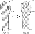
- FIGS. 1A-1B an exemplary process of forming a glove 100 is shown.
- a fabric layer 104 is placed on a glove mold (or form) 102.
- the glove mold 102, with the fabric layer 104 attached may be dipped into a material to form a chemical protection layer 106 (or outer layer), wherein the chemical protection layer 106 may comprise a plurality of hollow beads.
- the material of the chemical protection layer 106 may at least partially penetrate through the fabric layer 104, and may form a coating on the inner surface of the fabric layer 104, as well as the outer surface.
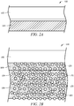
- FIGS. 2A-2B a cross-sectional view of the glove 100 is shown, where FIG. 2A corresponds to FIG. 1A and FIG. 2B corresponds to FIG. 1B .
- the fabric layer 104 is located adjacent to the glove mold 102.
- the glove mold 102 and fabric layer 104 have been dipped to apply the chemical protection layer 106.
- the chemical protection layer 106 may comprise a plurality of hollow beads 120, where the hollow beads 120 may be dispersed throughout the glove 100.
- the material of the chemical protection layer 106 may penetrate the fabric layer 104 to create an inner coating (or inner layer) 108 on the inner surface of the glove 100.
- the hollow beads 120 may penetrate through the fabric layer 104 as well, wherein the hollow beads 120 may be small enough to pass through any openings in the fabric layer 104.
- the hollow beads 120 may at least partially extend from the surface of the chemical protection layer 106, providing a textured surface on the outer layer of the glove 100.
- the hollow beads 120 at least partially extend from the surface of the inner coating 108 (or inner layer), providing a textured surface on the inner layer of the glove 100.
- the hollow beads 120 may be dispersed evenly throughout the chemical protection layer 106, fabric layer 104, and inner coating 108.
- the presence of the hollow beads 120 in the chemical protection layer 106 may not compromise the chemical protection qualities of the glove 100.
- the hollow beads 120 may influence the mechanical properties of the glove 100, especially abrasion, and this may be accounted for by including a crosslink agent in the formulation of the PU coating material.
- the hollow beads 120 may comprise a hollow glass material.
- the hollow beads 120 may comprise one or more materials including hollow glass beads, hollow polyvinyl chloride (PVC) beads, hollow polyvinyl alcohol (PVA) beads, polymethyl methacrylate (PMMA) and/or other hollow organic and inorganic beads.
- the hollow beads 120 may comprise a diameter less than approximately 50 micrometers ( ⁇ m).
- the hollow beads 120 may also be known as bubbles, spheres, microspheres, or particles. While described as being hollow, various other low-density materials including beads of micro foamed materials and the like (e.g., having a plurality of internal voids rather than a single internal void) can also be used. The beads formed from such materials can be made of the same materials and have the same dimensions as those described above.
- the glove 100 described above may provide improved comfort in wearing for a user. This may be demonstrated by the results of a comparison test with a typical PU glove that does not contain the hollow beads. Additionally, for reference, the glove 100 was compared with 100% lamb's wool, which may be considered a standard for softness and comfort. The results of the comparison test are shown below in Table 1. The testing was completed using a PhabrOmeter instrument, where a larger value indicates a higher dexterity and comfort. As can be seen in the table, the testing results for the glove containing the hollow beads are an improvement over the original (or typical) glove, and are closer in number to those results from the 100% lamb's wool.
- a process for making the glove described above may comprise preparing the PU coating dispersion, wherein the PU coating dispersion (or solution) may comprise PU, hollow beads, pigment, and solvent.
- the PU dispersion may be mixed by adding PU latex into the solvent (which may comprise dimethylformamide (DMF)). Then, the hollow beads and pigment may be added to the mixture, which may be stirred to control the viscosity of the solution.
- DMF dimethylformamide
- a fabric layer may be placed on the glove mold, and the mold and fabric may be dipped into the PU solution.
- the mold and fabric layer may be heated before dipping.
- the dipping process may comprise one dip into the solution or multiple dips into the solution.
- the dipping process may allow the mold and fabric to sit in the solution for a set amount of time.
- the dipping process may comprise leaching for approximately 30-40 minutes in hot water.
- the glove may be dried.
- the glove may be dried in an oven at approximately 70 to 120 degrees Celsius.
- the beads may float to and extend from the surface of the coating layers, creating the textured surfaces.
- the volume of the wet coating layer is decreased by drying (i.e. some of the coating layer evaporates away), the hollow beads may "appear" on the surfaces of the glove.
Landscapes
- Chemical & Material Sciences (AREA)
- Health & Medical Sciences (AREA)
- Engineering & Computer Science (AREA)
- General Health & Medical Sciences (AREA)
- Materials Engineering (AREA)
- Toxicology (AREA)
- Chemical Kinetics & Catalysis (AREA)
- General Chemical & Material Sciences (AREA)
- Business, Economics & Management (AREA)
- Emergency Management (AREA)
- Gloves (AREA)
Description
- Seamless, three-dimensional gloves may be formed using a glove mold and dipping the mold into a liquidized material that may dry to form the glove material. Such gloves may be used to protect a user's hands from chemicals, dust, grease, or other harmful substances. These gloves may be formed in varies sizes to accommodate the user.
-
US2016/029721 discloses a glove having an inner glove formed in the shape of a human hand, a protective member secured to the inner glove; and an outer glove attached to at least one of the inner glove and the protective member, the outer glove being formed in the shape of a human hand and configured to fit over the protective member and the inner glove.WO2015/074106 discloses gloves including a fabric liner; a first polymeric composition adhered to at least a portion of the fabric liner, forming a polymeric coating; and a plurality of raised features comprising a second polymeric composition disposed on a surface of the polymeric coating, wherein the polymeric coating and the plurality of raised features comprise different polymeric compositions adapted to enhance at least one of oil grip properties, dry grip properties, or wet grip properties.DE20318173 andDE20318069 disclose protective gloves, especially for protection against chemical weapons, containing a barrier layer comprising a water vapor permeable membrane between the carrier and adsorption layers.US2011/206920 discloses a method and an article of manufacture are disclosed for reinforcing various structures, such as pipes, ducts, vessels, tanks, silos, chimneys, and the like, constructed from various materials including steel, concrete, masonry, wood, plastics, and the like.WO2008/108775 discloses a chemically protective article comprising an outer shell and a separable adsorptive liner is provided. When the adsorption sites of the liner become saturated, the liner alone may be replaced without discarding the entire article.US2003/134063 discloses an elastomeric or polymer material or glove having enhanced cut or penetration resistance. - The invention is set out in accordance with the appended claims. In an embodiment, a chemical protection glove may comprise an outer layer comprising at least one layer of a chemically impermeable material comprising a polyurethane solution; a fabric layer located beneath the outer layer of the glove; and an inner layer configured to contact the user's skin comprising a plurality of hollow beads dispersed throughout the inner layer, wherein the hollow beads at least partially extend from the surface of the inner layer, and wherein the hollow beads create a textured surface on the inner layer;
wherein the outer layer (106) and inner layer (108) comprise a polyurethane solution; and wherein the polyurethane solution of the outer layer (106) extends through the fabric layer (104) to form the inner layer (108). - In an embodiment, a method for forming a chemical protection glove may comprise placing a fabric layer onto a glove mold; dipping the glove mold with the fabric layer into a polyurethane solution comprising a plurality of hollow beads; forming an outer layer of the polyurethane solution onto the fabric layer, wherein the hollow beads are dispersed through the outer layer; and forming an inner layer of the polyurethane solution by allowing the polyurethane solution to penetrate the fabric layer, wherein the hollow beads are dispersed throughout the inner layer.
- Preferably, the chemical protection glove may comprise an outer layer comprising at least one layer of a chemically impermeable material, and comprising a plurality of hollow beads dispersed throughout the outer layer, wherein the hollow beads at least partially extend from the surface of the outer layer, and wherein the hollow beads create a textured surface on the outer layer; a fabric layer located beneath the outer layer of the glove, wherein the material of the outer layer at least partially penetrates through the fabric layer; and an inner layer configured to contact the user's skin comprising a plurality of hollow beads dispersed throughout the inner layer, wherein the hollow beads at least partially extend from the surface of the inner layer, and wherein the hollow beads create a textured surface on the inner layer.
- For a more complete understanding of the present disclosure, reference is now made to the following brief description, taken in connection with the accompanying drawings and detailed description, wherein like reference numerals represent like parts.
-
FIGS. 1A-1B illustrate a method for forming a glove according to an embodiment of the disclosure; and -
FIGS. 2A-2B illustrate cross-sectional views of a glove according to an embodiment of the disclosure. - It should be understood at the outset that although illustrative implementations of one or more embodiments are illustrated below, the disclosed systems and methods may be implemented using any number of techniques, whether currently known or not yet in existence. The disclosure should in no way be limited to the illustrative implementations, drawings, and techniques illustrated below, but may be modified within the scope of the appended claims along with their full scope of equivalents.
- The following brief definition of terms shall apply throughout the application:
- The term "comprising" means including but not limited to, and should be interpreted in the manner it is typically used in the patent context;
- The phrases "in one embodiment," "according to one embodiment," and the like generally mean that the particular feature, structure, or characteristic following the phrase may be included in at least one embodiment of the present invention, and may be included in more than one embodiment of the present invention (importantly, such phrases do not necessarily refer to the same embodiment);
- If the specification describes something as "exemplary" or an "example," it should be understood that refers to a non-exclusive example;
- The terms "about" or "approximately" or the like, when used with a number, may mean that specific number, or alternatively, a range in proximity to the specific number, as understood by persons of skill in the art field; and
- If the specification states a component or feature "may," "can," "could," "should," "would," "preferably," "possibly," "typically," "optionally," "for example," "often," or "might" (or other such language) be included or have a characteristic, that particular component or feature is not required to be included or to have the characteristic. Such component or feature may be optionally included in some embodiments, or it may be excluded.
- Embodiments of the disclosure include methods and systems for creating a glove comprising a plurality of hollow beads located within the material of the glove. The hollow beads may be dispersed within a coating that is used to form at least one of the inner and/or outer surfaces of the glove.
- Typically, solvent based polyurethane (PU) has been used in the glove coating industry and may be preferred for its low cost and soft hand feeling. Unfortunately, problems may arise with using PU coatings, such as PU penetration and unacceptable coating edge appearance, which may lead to unpleasant hand feeling and unacceptable quality of glove appearance. Some users may be unsatisfied with the comfort levels of PU glove products, because of these issues.
- Embodiments of the disclosure comprises elements for improving the solvent based PU glove with ultra-soft hand feeling, improved wearing comfort, lightweight materials, and good coating edge quality.
- In typical solvent based PU coated gloves, the PU solution may penetrate through fabrics to form a coating on the inner surface of the glove. The inner coating may provide an unwelcome rubber-like feeling as it contacts the user's skin. Embodiments of the disclosure may comprise a plurality of hollow beads within the PU solution, where the hollow beads may also penetrate through the fabric and be present in the inner coating. The hollow beads may at least partially extend from the surface of the coating, creating raised bubbles or "nubbins" which may improve tactile feel for the user's hand. Additionally, the hollow beads may reduce the total weight of the glove by providing hollow areas throughout the material and reducing the amount of PU material that is required. For example, with the same thickness of coating created on the glove, the weight of the glove that incorporates the hollow beads may be reduced by approximately 40% when compared to a typical PU coated glove. In some embodiments, the hollow beads may provide a barrier to spreading of the PU solution, thereby creating a uniform coating edge.
- Referring now to
FIGS. 1A-1B , an exemplary process of forming aglove 100 is shown. InFIG. 1A , afabric layer 104 is placed on a glove mold (or form) 102. Then, theglove mold 102, with thefabric layer 104 attached, may be dipped into a material to form a chemical protection layer 106 (or outer layer), wherein thechemical protection layer 106 may comprise a plurality of hollow beads. In some embodiments, the material of thechemical protection layer 106 may at least partially penetrate through thefabric layer 104, and may form a coating on the inner surface of thefabric layer 104, as well as the outer surface. - Referring now to
FIGS. 2A-2B , a cross-sectional view of theglove 100 is shown, whereFIG. 2A corresponds toFIG. 1A andFIG. 2B corresponds toFIG. 1B . InFIG. 2A , thefabric layer 104 is located adjacent to theglove mold 102. Then inFIG. 2B , theglove mold 102 andfabric layer 104 have been dipped to apply thechemical protection layer 106. As described above, thechemical protection layer 106 may comprise a plurality ofhollow beads 120, where thehollow beads 120 may be dispersed throughout theglove 100. In some embodiments, the material of thechemical protection layer 106 may penetrate thefabric layer 104 to create an inner coating (or inner layer) 108 on the inner surface of theglove 100. In some embodiments, thehollow beads 120 may penetrate through thefabric layer 104 as well, wherein thehollow beads 120 may be small enough to pass through any openings in thefabric layer 104. In some embodiments, thehollow beads 120 may at least partially extend from the surface of thechemical protection layer 106, providing a textured surface on the outer layer of theglove 100. Thehollow beads 120 at least partially extend from the surface of the inner coating 108 (or inner layer), providing a textured surface on the inner layer of theglove 100. Thehollow beads 120 may be dispersed evenly throughout thechemical protection layer 106,fabric layer 104, andinner coating 108. - The presence of the
hollow beads 120 in thechemical protection layer 106 may not compromise the chemical protection qualities of theglove 100. Thehollow beads 120 may influence the mechanical properties of theglove 100, especially abrasion, and this may be accounted for by including a crosslink agent in the formulation of the PU coating material. - In some embodiments, the
hollow beads 120 may comprise a hollow glass material. In some embodiments, thehollow beads 120 may comprise one or more materials including hollow glass beads, hollow polyvinyl chloride (PVC) beads, hollow polyvinyl alcohol (PVA) beads, polymethyl methacrylate (PMMA) and/or other hollow organic and inorganic beads. In some embodiments, thehollow beads 120 may comprise a diameter less than approximately 50 micrometers (µm). In some embodiments, thehollow beads 120 may also be known as bubbles, spheres, microspheres, or particles. While described as being hollow, various other low-density materials including beads of micro foamed materials and the like (e.g., having a plurality of internal voids rather than a single internal void) can also be used. The beads formed from such materials can be made of the same materials and have the same dimensions as those described above. - In some embodiments, the
glove 100 described above may provide improved comfort in wearing for a user. This may be demonstrated by the results of a comparison test with a typical PU glove that does not contain the hollow beads. Additionally, for reference, theglove 100 was compared with 100% lamb's wool, which may be considered a standard for softness and comfort. The results of the comparison test are shown below in Table 1. The testing was completed using a PhabrOmeter instrument, where a larger value indicates a higher dexterity and comfort. As can be seen in the table, the testing results for the glove containing the hollow beads are an improvement over the original (or typical) glove, and are closer in number to those results from the 100% lamb's wool.Table 1: Comparison Test Results Sample Name Overall fabric hand Flexibility Smoothness Softness 100% Lamb's wool 1 0.8223 0.1008 0.9048 Glove (with Hollow Beads) 0.7916 0.5265 0.2131 0.7842 Glove (Original) 0.6146 0.247 0.096 0.7077 - A process for making the glove described above may comprise preparing the PU coating dispersion, wherein the PU coating dispersion (or solution) may comprise PU, hollow beads, pigment, and solvent. In some embodiments, the PU dispersion may be mixed by adding PU latex into the solvent (which may comprise dimethylformamide (DMF)). Then, the hollow beads and pigment may be added to the mixture, which may be stirred to control the viscosity of the solution.
- Then, a fabric layer may be placed on the glove mold, and the mold and fabric may be dipped into the PU solution. In some embodiments, the mold and fabric layer may be heated before dipping. The dipping process may comprise one dip into the solution or multiple dips into the solution. The dipping process may allow the mold and fabric to sit in the solution for a set amount of time. In some embodiments, the dipping process may comprise leaching for approximately 30-40 minutes in hot water.
- After the dipping process forms the inner and outer coating of the glove, the glove may be dried. For example, the glove may be dried in an oven at approximately 70 to 120 degrees Celsius. In some embodiments, during the drying process, the beads may float to and extend from the surface of the coating layers, creating the textured surfaces. In other words, when the volume of the wet coating layer is decreased by drying (i.e. some of the coating layer evaporates away), the hollow beads may "appear" on the surfaces of the glove.
- Additionally, the section headings used herein are provided for consistency or to otherwise provide organizational cues. These headings shall not limit or characterize the invention(s) set out in any claims that may issue from this disclosure. Specifically and by way of example, although the headings might refer to a "Field," the claims should not be limited by the language chosen under this heading to describe the so-called field. Further, a description of a technology in the "Background" is not to be construed as an admission that certain technology is prior art to any invention(s) in this disclosure. Neither is the "Summary" to be considered as a limiting characterization of the invention(s) set forth in issued claims. Furthermore, any reference in this disclosure to "invention" in the singular should not be used to argue that there is only a single point of novelty in this disclosure. Multiple inventions may be set forth according to the limitations of the multiple claims issuing from this disclosure, and such claims accordingly define the invention(s), and their equivalents, that are protected thereby. In all instances, the scope of the claims shall be considered on their own merits in light of this disclosure, but should not be constrained by the headings set forth herein.
- Use of broader terms such as "comprises," "includes," and "having" should be understood to provide support for narrower terms such as "consisting of," "consisting essentially of," and "comprised substantially of." Use of the terms "optionally," "may," "might," "possibly," and the like with respect to any element of an embodiment means that the element is not required, or alternatively, the element is required, both alternatives being within the scope of the embodiment(s). Also, references to examples are merely provided for illustrative purposes, and are not intended to be exclusive.
Claims (13)
- A chemical protection glove (100) comprising:an outer layer (106) comprising at least one layer of a chemically impermeable material comprising a polyurethane solution;a fabric layer (104) located beneath the outer layer (106); andan inner layer (108) configured to contact a user's skin comprising a plurality of hollow beads (120) dispersed throughout the inner layer (108), wherein the hollow beads (120) at least partially extend from a surface of the inner layer (108), and wherein the hollow beads (120) create a textured surface on the inner layer (108)wherein the outer layer (106) and inner layer (108) comprise a polyurethane solution; andwherein the polyurethane solution of the outer layer (106) extends through the fabric layer (104) to form the inner layer (108).
- The chemical protection glove (100) of claim 1, wherein the outer layer (106) comprises a plurality of hollow beads (120) dispersed throughout the outer layer (106), wherein the plurality of hollow beads (120) at least partially extend from the surface of the outer layer (106), and wherein the hollow beads (120) create a textured surface on the outer layer (106).
- The chemical protection glove (100) of claim 1, wherein the fabric layer (104) is saturated with a polyurethane solution comprising the hollow beads (120), and wherein the polyurethane solution extends through the fabric layer (104) to form the outer layer (106) and the inner layer (108).
- The chemical protection glove (100) of claim 3, wherein the polyurethane solution further comprises a dimethylformamide solvent.
- The chemical protection glove (100) of claim 1, wherein the hollow beads (120) have a diameter of less than or equal to about 50 micrometers.
- The chemical protection glove (100) of claim 1, wherein the hollow beads (120) comprise a hollow glass material.
- The chemical protection glove (100) of claim 1, wherein the hollow beads (120) comprise at least one of the following materials: hollow glass beads, hollow polyvinyl chloride beads, hollow polyvinyl alcohol beads, hollow polymethylmethacrylate beads, other hollow organic and inorganic beads, or any combination thereof.
- The chemical protection glove (100) of claim 1, wherein the polyurethane solution comprises a crosslink agent.
- A method for forming a chemical protection glove comprising:placing a fabric layer onto a glove mold;dipping the glove mold with the fabric layer into a polyurethane solution comprising a plurality of hollow beads;forming an outer layer of the polyurethane solution onto the fabric layer, wherein the hollow beads are dispersed through the outer layer; andforming an inner layer of the polyurethane solution by allowing the polyurethane solution to penetrate the fabric layer, wherein the hollow beads are dispersed throughout the inner layer.
- The method of claim 9, further comprising: drying the glove.
- The method of claim 9, further comprising: creating a textured surface on the inner layer by at least partially exposing the hollow beads of the inner layer.
- The method of claim 9, further comprising: creating a textured surface on the inner layer by at least partially exposing the hollow beads of the outer layer.
- The method of claim 9, further comprising: mixing the polyurethane solution, wherein the polyurethane solution comprises polyurethane latex, a solvent, the hollow beads, and a pigment.
Priority Applications (1)
| Application Number | Priority Date | Filing Date | Title |
|---|---|---|---|
| EP16191251.4A EP3300773B1 (en) | 2016-09-29 | 2016-09-29 | A method to produce ultra-soft solvent based polyurethane glove |
Applications Claiming Priority (1)
| Application Number | Priority Date | Filing Date | Title |
|---|---|---|---|
| EP16191251.4A EP3300773B1 (en) | 2016-09-29 | 2016-09-29 | A method to produce ultra-soft solvent based polyurethane glove |
Publications (2)
| Publication Number | Publication Date |
|---|---|
| EP3300773A1 EP3300773A1 (en) | 2018-04-04 |
| EP3300773B1 true EP3300773B1 (en) | 2019-09-25 |
Family
ID=57189743
Family Applications (1)
| Application Number | Title | Priority Date | Filing Date |
|---|---|---|---|
| EP16191251.4A Active EP3300773B1 (en) | 2016-09-29 | 2016-09-29 | A method to produce ultra-soft solvent based polyurethane glove |
Country Status (1)
| Country | Link |
|---|---|
| EP (1) | EP3300773B1 (en) |
Family Cites Families (7)
| Publication number | Priority date | Publication date | Assignee | Title |
|---|---|---|---|---|
| US7504145B2 (en) * | 2002-01-11 | 2009-03-17 | Higher Dimension Materials, Inc. | Polymeric material with resistant structure and method of making the same |
| DE20316856U1 (en) * | 2003-10-14 | 2004-11-25 | BLüCHER GMBH | Protective glove, especially for protection against chemical weapons, contains barrier layer comprising water vapor permeable membrane between carrier and adsorption layers |
| DE20317080U1 (en) * | 2003-10-22 | 2004-12-02 | BLüCHER GMBH | Protective clothing with ABC protection |
| WO2008108755A1 (en) * | 2007-03-05 | 2008-09-12 | E. I. Du Pont De Nemours And Company | Chemically protective articles with separable adsorptive liner |
| US20110206920A1 (en) * | 2008-09-19 | 2011-08-25 | Mohammad Reza Ehsani | Structure reinforcement wrap |
| US10349690B2 (en) * | 2013-11-25 | 2019-07-16 | Ansell Limited | Supported glove having grip features |
| US20160029721A1 (en) * | 2014-08-04 | 2016-02-04 | Group Industry, Llc | Concealed impact glove |
-
2016
- 2016-09-29 EP EP16191251.4A patent/EP3300773B1/en active Active
Non-Patent Citations (1)
| Title |
|---|
| None * |
Also Published As
| Publication number | Publication date |
|---|---|
| EP3300773A1 (en) | 2018-04-04 |
Similar Documents
| Publication | Publication Date | Title |
|---|---|---|
| US7788737B2 (en) | Cut resistant glove and apparel | |
| US20240410182A1 (en) | Flooring panel equipped with quick-release adhesive sheet and methods for making same | |
| US20130291283A1 (en) | Highly absorbant foamed lining | |
| WO2009028057A1 (en) | Fire-resistant piping material | |
| AU2015315577B2 (en) | A two-layer glass fiber mat composite | |
| WO2021244991A1 (en) | Slip-resistant floor coverings | |
| KR100468996B1 (en) | Building material and Method of Manufacturing Same | |
| CN105350741A (en) | Wood-plastic flooring and manufacturing method thereof | |
| WO2008120909A1 (en) | An impact sound insulation material of floors and floor construction method using the same | |
| JP2019060119A (en) | Floor material | |
| EP3300773A1 (en) | A method to produce ultra-soft solvent based polyurethane glove | |
| JP2024504535A (en) | Fully coated gloves with moisture and sweat absorption function | |
| JP7013665B2 (en) | Decorative sheet and manufacturing method of decorative sheet | |
| KR101555854B1 (en) | Composite floor board using ethylene vinyl acetate | |
| JP6733171B2 (en) | Foam wallpaper | |
| KR20160131499A (en) | Method for manufacutring vermiculite board | |
| JP4647069B2 (en) | Dirt remover | |
| KR20220095958A (en) | Method of coating structure with composition comprising microcement and constructure using the same | |
| KR20220095956A (en) | Method of coating structure with composition comprising microcement and constructure using the same | |
| KR20220095954A (en) | Method of coating structure with composition comprising microcement and constructure using the same | |
| JP7027906B2 (en) | Interior materials for restoration and interior restoration methods | |
| JP5323968B2 (en) | gloves | |
| JP2022099128A (en) | Flooring material | |
| CN101325886B (en) | Cut resistant glove and apparel | |
| KR101821758B1 (en) | Method for manufacturing functional wood |
Legal Events
| Date | Code | Title | Description |
|---|---|---|---|
| PUAI | Public reference made under article 153(3) epc to a published international application that has entered the european phase |
Free format text: ORIGINAL CODE: 0009012 |
|
| STAA | Information on the status of an ep patent application or granted ep patent |
Free format text: STATUS: REQUEST FOR EXAMINATION WAS MADE |
|
| 17P | Request for examination filed |
Effective date: 20160929 |
|
| AK | Designated contracting states |
Kind code of ref document: A1 Designated state(s): AL AT BE BG CH CY CZ DE DK EE ES FI FR GB GR HR HU IE IS IT LI LT LU LV MC MK MT NL NO PL PT RO RS SE SI SK SM TR |
|
| AX | Request for extension of the european patent |
Extension state: BA ME |
|
| STAA | Information on the status of an ep patent application or granted ep patent |
Free format text: STATUS: EXAMINATION IS IN PROGRESS |
|
| 17Q | First examination report despatched |
Effective date: 20180723 |
|
| GRAP | Despatch of communication of intention to grant a patent |
Free format text: ORIGINAL CODE: EPIDOSNIGR1 |
|
| STAA | Information on the status of an ep patent application or granted ep patent |
Free format text: STATUS: GRANT OF PATENT IS INTENDED |
|
| INTG | Intention to grant announced |
Effective date: 20190509 |
|
| GRAS | Grant fee paid |
Free format text: ORIGINAL CODE: EPIDOSNIGR3 |
|
| GRAA | (expected) grant |
Free format text: ORIGINAL CODE: 0009210 |
|
| STAA | Information on the status of an ep patent application or granted ep patent |
Free format text: STATUS: THE PATENT HAS BEEN GRANTED |
|
| AK | Designated contracting states |
Kind code of ref document: B1 Designated state(s): AL AT BE BG CH CY CZ DE DK EE ES FI FR GB GR HR HU IE IS IT LI LT LU LV MC MK MT NL NO PL PT RO RS SE SI SK SM TR |
|
| REG | Reference to a national code |
Ref country code: GB Ref legal event code: FG4D |
|
| REG | Reference to a national code |
Ref country code: CH Ref legal event code: EP |
|
| REG | Reference to a national code |
Ref country code: AT Ref legal event code: REF Ref document number: 1183247 Country of ref document: AT Kind code of ref document: T Effective date: 20191015 |
|
| REG | Reference to a national code |
Ref country code: IE Ref legal event code: FG4D |
|
| REG | Reference to a national code |
Ref country code: DE Ref legal event code: R096 Ref document number: 602016021148 Country of ref document: DE |
|
| REG | Reference to a national code |
Ref country code: NL Ref legal event code: MP Effective date: 20190925 |
|
| PG25 | Lapsed in a contracting state [announced via postgrant information from national office to epo] |
Ref country code: NO Free format text: LAPSE BECAUSE OF FAILURE TO SUBMIT A TRANSLATION OF THE DESCRIPTION OR TO PAY THE FEE WITHIN THE PRESCRIBED TIME-LIMIT Effective date: 20191225 Ref country code: BG Free format text: LAPSE BECAUSE OF FAILURE TO SUBMIT A TRANSLATION OF THE DESCRIPTION OR TO PAY THE FEE WITHIN THE PRESCRIBED TIME-LIMIT Effective date: 20191225 Ref country code: SE Free format text: LAPSE BECAUSE OF FAILURE TO SUBMIT A TRANSLATION OF THE DESCRIPTION OR TO PAY THE FEE WITHIN THE PRESCRIBED TIME-LIMIT Effective date: 20190925 Ref country code: FI Free format text: LAPSE BECAUSE OF FAILURE TO SUBMIT A TRANSLATION OF THE DESCRIPTION OR TO PAY THE FEE WITHIN THE PRESCRIBED TIME-LIMIT Effective date: 20190925 Ref country code: HR Free format text: LAPSE BECAUSE OF FAILURE TO SUBMIT A TRANSLATION OF THE DESCRIPTION OR TO PAY THE FEE WITHIN THE PRESCRIBED TIME-LIMIT Effective date: 20190925 Ref country code: LT Free format text: LAPSE BECAUSE OF FAILURE TO SUBMIT A TRANSLATION OF THE DESCRIPTION OR TO PAY THE FEE WITHIN THE PRESCRIBED TIME-LIMIT Effective date: 20190925 |
|
| REG | Reference to a national code |
Ref country code: LT Ref legal event code: MG4D |
|
| PG25 | Lapsed in a contracting state [announced via postgrant information from national office to epo] |
Ref country code: GR Free format text: LAPSE BECAUSE OF FAILURE TO SUBMIT A TRANSLATION OF THE DESCRIPTION OR TO PAY THE FEE WITHIN THE PRESCRIBED TIME-LIMIT Effective date: 20191226 Ref country code: RS Free format text: LAPSE BECAUSE OF FAILURE TO SUBMIT A TRANSLATION OF THE DESCRIPTION OR TO PAY THE FEE WITHIN THE PRESCRIBED TIME-LIMIT Effective date: 20190925 Ref country code: LV Free format text: LAPSE BECAUSE OF FAILURE TO SUBMIT A TRANSLATION OF THE DESCRIPTION OR TO PAY THE FEE WITHIN THE PRESCRIBED TIME-LIMIT Effective date: 20190925 |
|
| REG | Reference to a national code |
Ref country code: AT Ref legal event code: MK05 Ref document number: 1183247 Country of ref document: AT Kind code of ref document: T Effective date: 20190925 |
|
| PG25 | Lapsed in a contracting state [announced via postgrant information from national office to epo] |
Ref country code: AL Free format text: LAPSE BECAUSE OF FAILURE TO SUBMIT A TRANSLATION OF THE DESCRIPTION OR TO PAY THE FEE WITHIN THE PRESCRIBED TIME-LIMIT Effective date: 20190925 Ref country code: PT Free format text: LAPSE BECAUSE OF FAILURE TO SUBMIT A TRANSLATION OF THE DESCRIPTION OR TO PAY THE FEE WITHIN THE PRESCRIBED TIME-LIMIT Effective date: 20200127 Ref country code: ES Free format text: LAPSE BECAUSE OF FAILURE TO SUBMIT A TRANSLATION OF THE DESCRIPTION OR TO PAY THE FEE WITHIN THE PRESCRIBED TIME-LIMIT Effective date: 20190925 Ref country code: PL Free format text: LAPSE BECAUSE OF FAILURE TO SUBMIT A TRANSLATION OF THE DESCRIPTION OR TO PAY THE FEE WITHIN THE PRESCRIBED TIME-LIMIT Effective date: 20190925 Ref country code: RO Free format text: LAPSE BECAUSE OF FAILURE TO SUBMIT A TRANSLATION OF THE DESCRIPTION OR TO PAY THE FEE WITHIN THE PRESCRIBED TIME-LIMIT Effective date: 20190925 Ref country code: IT Free format text: LAPSE BECAUSE OF FAILURE TO SUBMIT A TRANSLATION OF THE DESCRIPTION OR TO PAY THE FEE WITHIN THE PRESCRIBED TIME-LIMIT Effective date: 20190925 Ref country code: NL Free format text: LAPSE BECAUSE OF FAILURE TO SUBMIT A TRANSLATION OF THE DESCRIPTION OR TO PAY THE FEE WITHIN THE PRESCRIBED TIME-LIMIT Effective date: 20190925 Ref country code: EE Free format text: LAPSE BECAUSE OF FAILURE TO SUBMIT A TRANSLATION OF THE DESCRIPTION OR TO PAY THE FEE WITHIN THE PRESCRIBED TIME-LIMIT Effective date: 20190925 Ref country code: AT Free format text: LAPSE BECAUSE OF FAILURE TO SUBMIT A TRANSLATION OF THE DESCRIPTION OR TO PAY THE FEE WITHIN THE PRESCRIBED TIME-LIMIT Effective date: 20190925 |
|
| PG25 | Lapsed in a contracting state [announced via postgrant information from national office to epo] |
Ref country code: CZ Free format text: LAPSE BECAUSE OF FAILURE TO SUBMIT A TRANSLATION OF THE DESCRIPTION OR TO PAY THE FEE WITHIN THE PRESCRIBED TIME-LIMIT Effective date: 20190925 Ref country code: SM Free format text: LAPSE BECAUSE OF FAILURE TO SUBMIT A TRANSLATION OF THE DESCRIPTION OR TO PAY THE FEE WITHIN THE PRESCRIBED TIME-LIMIT Effective date: 20190925 Ref country code: IS Free format text: LAPSE BECAUSE OF FAILURE TO SUBMIT A TRANSLATION OF THE DESCRIPTION OR TO PAY THE FEE WITHIN THE PRESCRIBED TIME-LIMIT Effective date: 20200224 Ref country code: SK Free format text: LAPSE BECAUSE OF FAILURE TO SUBMIT A TRANSLATION OF THE DESCRIPTION OR TO PAY THE FEE WITHIN THE PRESCRIBED TIME-LIMIT Effective date: 20190925 |
|
| REG | Reference to a national code |
Ref country code: CH Ref legal event code: PL |
|
| REG | Reference to a national code |
Ref country code: DE Ref legal event code: R097 Ref document number: 602016021148 Country of ref document: DE |
|
| PG2D | Information on lapse in contracting state deleted |
Ref country code: IS |
|
| PG25 | Lapsed in a contracting state [announced via postgrant information from national office to epo] |
Ref country code: LI Free format text: LAPSE BECAUSE OF NON-PAYMENT OF DUE FEES Effective date: 20190930 Ref country code: DK Free format text: LAPSE BECAUSE OF FAILURE TO SUBMIT A TRANSLATION OF THE DESCRIPTION OR TO PAY THE FEE WITHIN THE PRESCRIBED TIME-LIMIT Effective date: 20190925 Ref country code: LU Free format text: LAPSE BECAUSE OF NON-PAYMENT OF DUE FEES Effective date: 20190929 Ref country code: CH Free format text: LAPSE BECAUSE OF NON-PAYMENT OF DUE FEES Effective date: 20190930 Ref country code: IE Free format text: LAPSE BECAUSE OF NON-PAYMENT OF DUE FEES Effective date: 20190929 Ref country code: IS Free format text: LAPSE BECAUSE OF FAILURE TO SUBMIT A TRANSLATION OF THE DESCRIPTION OR TO PAY THE FEE WITHIN THE PRESCRIBED TIME-LIMIT Effective date: 20200126 |
|
| PLBE | No opposition filed within time limit |
Free format text: ORIGINAL CODE: 0009261 |
|
| STAA | Information on the status of an ep patent application or granted ep patent |
Free format text: STATUS: NO OPPOSITION FILED WITHIN TIME LIMIT |
|
| REG | Reference to a national code |
Ref country code: BE Ref legal event code: MM Effective date: 20190930 |
|
| PG25 | Lapsed in a contracting state [announced via postgrant information from national office to epo] |
Ref country code: MC Free format text: LAPSE BECAUSE OF FAILURE TO SUBMIT A TRANSLATION OF THE DESCRIPTION OR TO PAY THE FEE WITHIN THE PRESCRIBED TIME-LIMIT Effective date: 20190925 Ref country code: BE Free format text: LAPSE BECAUSE OF NON-PAYMENT OF DUE FEES Effective date: 20190930 |
|
| 26N | No opposition filed |
Effective date: 20200626 |
|
| PG25 | Lapsed in a contracting state [announced via postgrant information from national office to epo] |
Ref country code: SI Free format text: LAPSE BECAUSE OF FAILURE TO SUBMIT A TRANSLATION OF THE DESCRIPTION OR TO PAY THE FEE WITHIN THE PRESCRIBED TIME-LIMIT Effective date: 20190925 |
|
| REG | Reference to a national code |
Ref country code: DE Ref legal event code: R082 Ref document number: 602016021148 Country of ref document: DE Representative=s name: HL KEMPNER PATENTANWAELTE, SOLICITORS (ENGLAND, DE Ref country code: DE Ref legal event code: R082 Ref document number: 602016021148 Country of ref document: DE Representative=s name: HL KEMPNER PATENTANWALT, RECHTSANWALT, SOLICIT, DE Ref country code: DE Ref legal event code: R082 Ref document number: 602016021148 Country of ref document: DE Representative=s name: HL KEMPNER PARTG MBB, DE |
|
| PG25 | Lapsed in a contracting state [announced via postgrant information from national office to epo] |
Ref country code: CY Free format text: LAPSE BECAUSE OF FAILURE TO SUBMIT A TRANSLATION OF THE DESCRIPTION OR TO PAY THE FEE WITHIN THE PRESCRIBED TIME-LIMIT Effective date: 20190925 |
|
| PG25 | Lapsed in a contracting state [announced via postgrant information from national office to epo] |
Ref country code: MT Free format text: LAPSE BECAUSE OF FAILURE TO SUBMIT A TRANSLATION OF THE DESCRIPTION OR TO PAY THE FEE WITHIN THE PRESCRIBED TIME-LIMIT Effective date: 20190925 Ref country code: HU Free format text: LAPSE BECAUSE OF FAILURE TO SUBMIT A TRANSLATION OF THE DESCRIPTION OR TO PAY THE FEE WITHIN THE PRESCRIBED TIME-LIMIT; INVALID AB INITIO Effective date: 20160929 |
|
| PG25 | Lapsed in a contracting state [announced via postgrant information from national office to epo] |
Ref country code: TR Free format text: LAPSE BECAUSE OF FAILURE TO SUBMIT A TRANSLATION OF THE DESCRIPTION OR TO PAY THE FEE WITHIN THE PRESCRIBED TIME-LIMIT Effective date: 20190925 |
|
| PG25 | Lapsed in a contracting state [announced via postgrant information from national office to epo] |
Ref country code: MK Free format text: LAPSE BECAUSE OF FAILURE TO SUBMIT A TRANSLATION OF THE DESCRIPTION OR TO PAY THE FEE WITHIN THE PRESCRIBED TIME-LIMIT Effective date: 20190925 |
|
| REG | Reference to a national code |
Ref country code: DE Ref legal event code: R081 Ref document number: 602016021148 Country of ref document: DE Owner name: HONEYWELL SAFETY PRODUCTS USA, INC., WILMINGTO, US Free format text: FORMER OWNER: HONEYWELL INTERNATIONAL INC., MORRIS PLAINS, N.J., US |
|
| REG | Reference to a national code |
Ref country code: GB Ref legal event code: 732E Free format text: REGISTERED BETWEEN 20250515 AND 20250521 |
|
| PGFP | Annual fee paid to national office [announced via postgrant information from national office to epo] |
Ref country code: DE Payment date: 20250926 Year of fee payment: 10 |
|
| PGFP | Annual fee paid to national office [announced via postgrant information from national office to epo] |
Ref country code: GB Payment date: 20250923 Year of fee payment: 10 |
|
| PGFP | Annual fee paid to national office [announced via postgrant information from national office to epo] |
Ref country code: FR Payment date: 20250925 Year of fee payment: 10 |