EP3300162A1 - Battery swelling sensing system and method - Google Patents
Battery swelling sensing system and method Download PDFInfo
- Publication number
- EP3300162A1 EP3300162A1 EP16846758.7A EP16846758A EP3300162A1 EP 3300162 A1 EP3300162 A1 EP 3300162A1 EP 16846758 A EP16846758 A EP 16846758A EP 3300162 A1 EP3300162 A1 EP 3300162A1
- Authority
- EP
- European Patent Office
- Prior art keywords
- level
- detection value
- battery
- control unit
- detecting
- Prior art date
- Legal status (The legal status is an assumption and is not a legal conclusion. Google has not performed a legal analysis and makes no representation as to the accuracy of the status listed.)
- Granted
Links
- 230000008961 swelling Effects 0.000 title claims abstract description 52
- 238000000034 method Methods 0.000 title claims description 24
- 238000001514 detection method Methods 0.000 claims abstract description 131
- 230000002093 peripheral effect Effects 0.000 claims abstract description 14
- 206010042674 Swelling Diseases 0.000 claims description 50
- CURLTUGMZLYLDI-UHFFFAOYSA-N Carbon dioxide Chemical compound O=C=O CURLTUGMZLYLDI-UHFFFAOYSA-N 0.000 claims description 34
- VNWKTOKETHGBQD-UHFFFAOYSA-N methane Chemical compound C VNWKTOKETHGBQD-UHFFFAOYSA-N 0.000 claims description 34
- UGFAIRIUMAVXCW-UHFFFAOYSA-N Carbon monoxide Chemical compound [O+]#[C-] UGFAIRIUMAVXCW-UHFFFAOYSA-N 0.000 claims description 17
- 229910002092 carbon dioxide Inorganic materials 0.000 claims description 17
- 239000001569 carbon dioxide Substances 0.000 claims description 17
- 229910002091 carbon monoxide Inorganic materials 0.000 claims description 17
- 238000001816 cooling Methods 0.000 description 9
- 238000010586 diagram Methods 0.000 description 9
- 238000004891 communication Methods 0.000 description 5
- 239000000470 constituent Substances 0.000 description 4
- 230000002159 abnormal effect Effects 0.000 description 3
- 230000000903 blocking effect Effects 0.000 description 3
- 238000005516 engineering process Methods 0.000 description 3
- 238000004880 explosion Methods 0.000 description 3
- 230000008901 benefit Effects 0.000 description 2
- 230000003247 decreasing effect Effects 0.000 description 2
- 239000002075 main ingredient Substances 0.000 description 2
- 238000012544 monitoring process Methods 0.000 description 2
- 230000035945 sensitivity Effects 0.000 description 2
- 230000009471 action Effects 0.000 description 1
- 239000006227 byproduct Substances 0.000 description 1
- 230000008859 change Effects 0.000 description 1
- 238000006243 chemical reaction Methods 0.000 description 1
- 238000002485 combustion reaction Methods 0.000 description 1
- 238000007599 discharging Methods 0.000 description 1
- 230000000694 effects Effects 0.000 description 1
- 238000004146 energy storage Methods 0.000 description 1
- 230000003203 everyday effect Effects 0.000 description 1
- 230000005669 field effect Effects 0.000 description 1
- 239000002803 fossil fuel Substances 0.000 description 1
- 238000012423 maintenance Methods 0.000 description 1
- 238000012986 modification Methods 0.000 description 1
- 230000004048 modification Effects 0.000 description 1
- 238000002360 preparation method Methods 0.000 description 1
- 238000012545 processing Methods 0.000 description 1
- 239000000047 product Substances 0.000 description 1
- 230000001737 promoting effect Effects 0.000 description 1
- 230000008439 repair process Effects 0.000 description 1
- 238000012827 research and development Methods 0.000 description 1
- 238000004904 shortening Methods 0.000 description 1
- 238000011895 specific detection Methods 0.000 description 1
- 239000000126 substance Substances 0.000 description 1
Images


Classifications
-
- H—ELECTRICITY
- H01—ELECTRIC ELEMENTS
- H01M—PROCESSES OR MEANS, e.g. BATTERIES, FOR THE DIRECT CONVERSION OF CHEMICAL ENERGY INTO ELECTRICAL ENERGY
- H01M10/00—Secondary cells; Manufacture thereof
- H01M10/42—Methods or arrangements for servicing or maintenance of secondary cells or secondary half-cells
- H01M10/4207—Methods or arrangements for servicing or maintenance of secondary cells or secondary half-cells for several batteries or cells simultaneously or sequentially
-
- B—PERFORMING OPERATIONS; TRANSPORTING
- B60—VEHICLES IN GENERAL
- B60L—PROPULSION OF ELECTRICALLY-PROPELLED VEHICLES; SUPPLYING ELECTRIC POWER FOR AUXILIARY EQUIPMENT OF ELECTRICALLY-PROPELLED VEHICLES; ELECTRODYNAMIC BRAKE SYSTEMS FOR VEHICLES IN GENERAL; MAGNETIC SUSPENSION OR LEVITATION FOR VEHICLES; MONITORING OPERATING VARIABLES OF ELECTRICALLY-PROPELLED VEHICLES; ELECTRIC SAFETY DEVICES FOR ELECTRICALLY-PROPELLED VEHICLES
- B60L3/00—Electric devices on electrically-propelled vehicles for safety purposes; Monitoring operating variables, e.g. speed, deceleration or energy consumption
- B60L3/0023—Detecting, eliminating, remedying or compensating for drive train abnormalities, e.g. failures within the drive train
- B60L3/0046—Detecting, eliminating, remedying or compensating for drive train abnormalities, e.g. failures within the drive train relating to electric energy storage systems, e.g. batteries or capacitors
-
- B—PERFORMING OPERATIONS; TRANSPORTING
- B60—VEHICLES IN GENERAL
- B60L—PROPULSION OF ELECTRICALLY-PROPELLED VEHICLES; SUPPLYING ELECTRIC POWER FOR AUXILIARY EQUIPMENT OF ELECTRICALLY-PROPELLED VEHICLES; ELECTRODYNAMIC BRAKE SYSTEMS FOR VEHICLES IN GENERAL; MAGNETIC SUSPENSION OR LEVITATION FOR VEHICLES; MONITORING OPERATING VARIABLES OF ELECTRICALLY-PROPELLED VEHICLES; ELECTRIC SAFETY DEVICES FOR ELECTRICALLY-PROPELLED VEHICLES
- B60L58/00—Methods or circuit arrangements for monitoring or controlling batteries or fuel cells, specially adapted for electric vehicles
- B60L58/10—Methods or circuit arrangements for monitoring or controlling batteries or fuel cells, specially adapted for electric vehicles for monitoring or controlling batteries
- B60L58/12—Methods or circuit arrangements for monitoring or controlling batteries or fuel cells, specially adapted for electric vehicles for monitoring or controlling batteries responding to state of charge [SoC]
- B60L58/15—Preventing overcharging
-
- B—PERFORMING OPERATIONS; TRANSPORTING
- B60—VEHICLES IN GENERAL
- B60L—PROPULSION OF ELECTRICALLY-PROPELLED VEHICLES; SUPPLYING ELECTRIC POWER FOR AUXILIARY EQUIPMENT OF ELECTRICALLY-PROPELLED VEHICLES; ELECTRODYNAMIC BRAKE SYSTEMS FOR VEHICLES IN GENERAL; MAGNETIC SUSPENSION OR LEVITATION FOR VEHICLES; MONITORING OPERATING VARIABLES OF ELECTRICALLY-PROPELLED VEHICLES; ELECTRIC SAFETY DEVICES FOR ELECTRICALLY-PROPELLED VEHICLES
- B60L58/00—Methods or circuit arrangements for monitoring or controlling batteries or fuel cells, specially adapted for electric vehicles
- B60L58/10—Methods or circuit arrangements for monitoring or controlling batteries or fuel cells, specially adapted for electric vehicles for monitoring or controlling batteries
- B60L58/18—Methods or circuit arrangements for monitoring or controlling batteries or fuel cells, specially adapted for electric vehicles for monitoring or controlling batteries of two or more battery modules
- B60L58/21—Methods or circuit arrangements for monitoring or controlling batteries or fuel cells, specially adapted for electric vehicles for monitoring or controlling batteries of two or more battery modules having the same nominal voltage
-
- H—ELECTRICITY
- H01—ELECTRIC ELEMENTS
- H01M—PROCESSES OR MEANS, e.g. BATTERIES, FOR THE DIRECT CONVERSION OF CHEMICAL ENERGY INTO ELECTRICAL ENERGY
- H01M10/00—Secondary cells; Manufacture thereof
- H01M10/42—Methods or arrangements for servicing or maintenance of secondary cells or secondary half-cells
- H01M10/4285—Testing apparatus
-
- H—ELECTRICITY
- H01—ELECTRIC ELEMENTS
- H01M—PROCESSES OR MEANS, e.g. BATTERIES, FOR THE DIRECT CONVERSION OF CHEMICAL ENERGY INTO ELECTRICAL ENERGY
- H01M10/00—Secondary cells; Manufacture thereof
- H01M10/42—Methods or arrangements for servicing or maintenance of secondary cells or secondary half-cells
- H01M10/48—Accumulators combined with arrangements for measuring, testing or indicating the condition of cells, e.g. the level or density of the electrolyte
- H01M10/482—Accumulators combined with arrangements for measuring, testing or indicating the condition of cells, e.g. the level or density of the electrolyte for several batteries or cells simultaneously or sequentially
-
- H—ELECTRICITY
- H01—ELECTRIC ELEMENTS
- H01M—PROCESSES OR MEANS, e.g. BATTERIES, FOR THE DIRECT CONVERSION OF CHEMICAL ENERGY INTO ELECTRICAL ENERGY
- H01M50/00—Constructional details or processes of manufacture of the non-active parts of electrochemical cells other than fuel cells, e.g. hybrid cells
- H01M50/20—Mountings; Secondary casings or frames; Racks, modules or packs; Suspension devices; Shock absorbers; Transport or carrying devices; Holders
-
- H—ELECTRICITY
- H01—ELECTRIC ELEMENTS
- H01M—PROCESSES OR MEANS, e.g. BATTERIES, FOR THE DIRECT CONVERSION OF CHEMICAL ENERGY INTO ELECTRICAL ENERGY
- H01M50/00—Constructional details or processes of manufacture of the non-active parts of electrochemical cells other than fuel cells, e.g. hybrid cells
- H01M50/50—Current conducting connections for cells or batteries
- H01M50/572—Means for preventing undesired use or discharge
- H01M50/574—Devices or arrangements for the interruption of current
-
- H—ELECTRICITY
- H02—GENERATION; CONVERSION OR DISTRIBUTION OF ELECTRIC POWER
- H02J—CIRCUIT ARRANGEMENTS OR SYSTEMS FOR SUPPLYING OR DISTRIBUTING ELECTRIC POWER; SYSTEMS FOR STORING ELECTRIC ENERGY
- H02J7/00—Circuit arrangements for charging or depolarising batteries or for supplying loads from batteries
- H02J7/007—Regulation of charging or discharging current or voltage
- H02J7/007188—Regulation of charging or discharging current or voltage the charge cycle being controlled or terminated in response to non-electric parameters
- H02J7/00719—Regulation of charging or discharging current or voltage the charge cycle being controlled or terminated in response to non-electric parameters in response to degree of gas development in the battery
-
- G—PHYSICS
- G01—MEASURING; TESTING
- G01N—INVESTIGATING OR ANALYSING MATERIALS BY DETERMINING THEIR CHEMICAL OR PHYSICAL PROPERTIES
- G01N33/00—Investigating or analysing materials by specific methods not covered by groups G01N1/00 - G01N31/00
- G01N33/0004—Gaseous mixtures, e.g. polluted air
-
- H—ELECTRICITY
- H01—ELECTRIC ELEMENTS
- H01M—PROCESSES OR MEANS, e.g. BATTERIES, FOR THE DIRECT CONVERSION OF CHEMICAL ENERGY INTO ELECTRICAL ENERGY
- H01M2200/00—Safety devices for primary or secondary batteries
-
- H—ELECTRICITY
- H01—ELECTRIC ELEMENTS
- H01M—PROCESSES OR MEANS, e.g. BATTERIES, FOR THE DIRECT CONVERSION OF CHEMICAL ENERGY INTO ELECTRICAL ENERGY
- H01M2220/00—Batteries for particular applications
- H01M2220/20—Batteries in motive systems, e.g. vehicle, ship, plane
-
- Y—GENERAL TAGGING OF NEW TECHNOLOGICAL DEVELOPMENTS; GENERAL TAGGING OF CROSS-SECTIONAL TECHNOLOGIES SPANNING OVER SEVERAL SECTIONS OF THE IPC; TECHNICAL SUBJECTS COVERED BY FORMER USPC CROSS-REFERENCE ART COLLECTIONS [XRACs] AND DIGESTS
- Y02—TECHNOLOGIES OR APPLICATIONS FOR MITIGATION OR ADAPTATION AGAINST CLIMATE CHANGE
- Y02E—REDUCTION OF GREENHOUSE GAS [GHG] EMISSIONS, RELATED TO ENERGY GENERATION, TRANSMISSION OR DISTRIBUTION
- Y02E60/00—Enabling technologies; Technologies with a potential or indirect contribution to GHG emissions mitigation
- Y02E60/10—Energy storage using batteries
-
- Y—GENERAL TAGGING OF NEW TECHNOLOGICAL DEVELOPMENTS; GENERAL TAGGING OF CROSS-SECTIONAL TECHNOLOGIES SPANNING OVER SEVERAL SECTIONS OF THE IPC; TECHNICAL SUBJECTS COVERED BY FORMER USPC CROSS-REFERENCE ART COLLECTIONS [XRACs] AND DIGESTS
- Y02—TECHNOLOGIES OR APPLICATIONS FOR MITIGATION OR ADAPTATION AGAINST CLIMATE CHANGE
- Y02T—CLIMATE CHANGE MITIGATION TECHNOLOGIES RELATED TO TRANSPORTATION
- Y02T10/00—Road transport of goods or passengers
- Y02T10/60—Other road transportation technologies with climate change mitigation effect
- Y02T10/70—Energy storage systems for electromobility, e.g. batteries
Definitions
- the present invention relates to a system and a method of detecting swelling of a battery, and particularly, to a system and a method of detecting swelling of a battery, in which detecting units are dispersed inside a battery module to detect gas branched from battery cells, a level is given to the largest detection value among the values that exceed a threshold value according to a size of a detection value, and an operation of a battery circuit, an operation speed of a vehicle, and the like are controlled based on the corresponding level, thereby preventing an accident due to a swelling phenomenon of the battery cell.
- a battery has a characteristic in an easy application according to a product group, excellent preservability, a high energy density, and the like. Further, the battery attracts attention as an energy source for improving an environmentally-friendly characteristic and energy efficiency in that a by-product according to the use of energy is not generated, as well as a primary advantage in that it is possible to decrease the use of fossil fuel.
- the battery is universally applied to a portable device, an electric vehicle (EV), and an energy storage system (ESS), and the like, and serves as a basis in various industries and simultaneously provide convenience to everyday life.
- EV electric vehicle
- ESS energy storage system
- the battery may be abnormally driven according to a usage environment, and for example, when a battery is overcharged or a lifetime of the battery is exhausted, a swelling phenomenon and the like of the battery may be caused due to an electrical and chemical action generated inside the battery.
- the swelling phenomenon of the battery may lead to an accident, such as ignition and explosion, as well as shortening of the lifetime of the battery and a decrease in capacity of the battery, so that there is a demand for a stable usage of the battery through careful monitoring and an appropriate control.
- a technology of blocking a current by fracturing a member, such as a bus bar and a tap, by expansive force of the battery cell by the swelling phenomenon is also present.
- the present invention is conceived to solve the foregoing problems, and an object of the present invention is to provide a system and a method of detecting swelling of a battery, which detect gas branched from a battery cell in real time and determine a level of a detection value, and control a supply of power to a battery module, a current charging quantity, and the like based on the corresponding level, thereby solving a function problem of a battery incurrable due to a swelling phenomenon of the battery cell.
- an object of the present invention is to provide a system and a method of detecting swelling of a battery, which appropriately control an operation speed of a vehicle according to a level of a detection value, as well as a control of an operation of a battery circuit, thereby preventing an accident, such as explosion and ignition of the battery and the vehicle, and securing safety of a passenger of the vehicle.
- Another object of the present invention is to provide a system and a method of detecting swelling of a battery, which when a battery cell is present in an abnormal environment, control an operation of a peripheral apparatus, such as a air-cooling type fan and a water-cooling type cooling valve, to be stopped, thereby preventing power consumption by unnecessary driving of the peripheral apparatus.
- a peripheral apparatus such as a air-cooling type fan and a water-cooling type cooling valve
- a system for detecting swelling of a battery includes: a plurality of detecting units which is provided at one or more battery modules of a battery pack, respectively, and detects gas branched from a battery cell of the battery module; a control unit which selects the largest detection value among the detection values of the respective detecting units, determines a level of the selected detection value according to a size of the selected detection value, and controls an operation of a peripheral apparatus based on the corresponding level; and a switch unit which is provided in a connection path of the battery pack and an external power source and is turned on and off according to a signal of the control unit.
- the detecting units may be dispersed at upper, lower, left, right, front, and rear sides inside the battery module.
- Each of the detecting units may include a carbon monoxide detecting sensor, a carbon dioxide detecting sensor, and a methane detecting sensor.
- the detecting value may be formed as one set of values including a carbon monoxide detection value, a carbon dioxide detection value, and a methane detection value.
- the control unit may compare the detection value of each of the detecting units with a predetermined threshold value, select the largest detection value among the detection values exceeding the threshold values, and determine a level of the selected detection value according to the size of the selected detection value.
- the level of the selected detection value may be determined as one of a first level, a second level, and a third level according to the degree of swelling risk.
- the control unit may transmit a vehicle speed control signal based on the corresponding level to an electronic control unit (ECU) of a vehicle.
- ECU electronice control unit
- control unit may transmit an off operation signal to the switch unit after a predetermined time elapses.
- control unit may transmit a predetermined alarm signal to a display device pre-installed in a vehicle.
- control unit may control the quantity of charging current flowing into the battery pack from the external power source.
- a method of detecting swelling of a battery includes: detecting, by a plurality of detecting units provided at one or more battery modules of a battery pack, respectively, gas branched from a battery cell of the battery module; selecting, by a control unit, the largest detection value among the detection values of the respective detecting units, determining a level of the selected detection value according to a size of the selected detection value, and controlling an operation of a peripheral apparatus based on the corresponding level; and being turned on and off, by a switch unit provided in a connection path of the battery pack and an external power source, according to a signal of the control unit.
- the detecting units may be dispersed at upper, lower, left, right, front, and rear sides inside the battery module.
- Each of the detecting units may include a carbon monoxide detecting sensor, a carbon dioxide detecting sensor, and a methane detecting sensor.
- the detecting value may be formed as one set of values including a carbon monoxide detection value, a carbon dioxide detection value, and a methane detection value.
- the controlling may include comparing, by the control unit, the detection value of each of the detecting units with a predetermined threshold value, selecting the largest detection value among the detection values exceeding the threshold values, and determining a level of the selected detection value according to the size of the selected detection value.
- the level of the selected detection value may be determined as one of a first level, a second level, and a third level according to the degree of swelling risk.
- the controlling may include, when the level of the selected detection value is determined as one of the first level, the second level, and the third level, transmitting a vehicle speed control signal based on the corresponding level to an electronic control unit (ECU) of a vehicle.
- ECU electronice control unit
- the controlling may further include, when the level of the selected detection value is determined as the third level, transmitting an off operation signal to the switch unit after a predetermined time elapses.
- the controlling may further include, when the level of the selected detection value is determined as the third level, transmitting a predetermined alarm signal to a display device pre-installed in a vehicle.
- the controlling may further include, when the level of the selected detection value is determined as the second level, controlling the quantity of charging current flowing into the battery pack from the external power source.
- gas branched from a battery cell is detected in real time and a level is determined according to a size of the detected detection value, and an operation of a battery circuit is controlled based on the corresponding level, thereby decreasing danger of an accident incurrable due to a swelling phenomenon and improving efficiency of an operation of a battery while excluding a simple stop of the operation of the battery.
- the plurality of detecting units detecting branched gas is dispersed inside the battery modules, respectively, so that it is possible to improve sensitivity of a detection of gas, and partially replace only a corresponding battery module, in which a swelling phenomenon is incurred, among the plurality of battery modules, thereby promoting convenience of maintenance and repair and decreasing costs.
- a speed of an operated vehicle is controlled by using a battery as driving energy according to a level of a detection value, thereby preventing an accident incurrable due to an overspeeding operation and securing safety of a passenger of a vehicle when the swelling of the battery cell is incurred.
- a supply of power to a battery pack is stopped and an operation of a peripheral apparatus, such as an air-cooling type fan and a water-cooling type cooling value, is stopped, thereby preventing power consumption by unnecessary driving of the peripheral apparatus.
- a peripheral apparatus such as an air-cooling type fan and a water-cooling type cooling value
- ... unit described in the specification means a unit for processing at least one function and operation and may be implemented by hardware components or software components and combinations thereof.
- FIG. 1 is a diagram schematically illustrating an electric vehicle 1, to which a system and a method of detecting swelling of a battery according to an exemplary embodiment of the present invention are applicable.
- the system and the method of detecting swelling of the battery according to the exemplary embodiment of the present invention are applicable to various technical fields, to which a battery is applied, in addition to the electric vehicle 1.
- the electric vehicle 1 may include a battery 10, a battery management system (BMS) 20, an electronic control unit (ECU) 30, an inverter 40, and a motor 50.
- BMS battery management system
- ECU electronice control unit
- the battery 10 is an electric energy source providing driving force to the motor 50 and driving the electric vehicle 1, and may be charged or discharged by the inverter 40 according to the driving of the motor 50 and/or an internal combustion engine (not illustrated).
- the BMS 20 may estimate a state of the battery 10 and control a charging/discharging current of the battery 10 by using information about the state, and further control an opening/closing operation of a contactor.
- the ECU 30 is an electronic control apparatus controlling a state of the electric vehicle 1, and for example, may determine a degree of torque based on information about an accelerator, a break, a speed, and the like, and control an output of the motor to correspond to the torque information.
- the inverter 40 may charge or discharge the battery 10 based on a control signal of the ECU 30, and the motor 50 may drive the electric vehicle 1 based on electric energy of the battery 10 and the control information transmitted from the ECU 30.
- the battery 10 is a core element providing driving force, and when the battery 10 is in an abnormal state, this may cause a failure of the electric vehicle 1 and various accidents.
- the monitoring of a state of the battery 10 and an appropriate protection of the battery 10 according to a situation are the important matters for stably operating the battery 10 and are preparations for preventing various accidents due to abnormal driving of the battery 10 and securing safety of a passenger, and hereinafter, the system and the method of detecting swelling of the battery according to the exemplary embodiment of the present invention will be described with reference to FIGS. 2 to 5 .
- FIG. 2 is a diagram schematically illustrating a circuit diagram of the system 100 for detecting swelling of the battery according to the exemplary embodiment of the present invention.
- the system 100 for detecting swelling of the battery may include a plurality of detecting units 120, a control unit 130, and a switch unit 140.
- the system 100 for detecting the swelling of the battery illustrated in FIG. 2 is an exemplary embodiment, and constituent elements thereof are not limited to the exemplary embodiment illustrated in FIG. 2 , and it is noted that some constituent elements may be added, changed, or removed as necessary.
- each of the battery packs 110 also includes one or more battery modules 111, and similarly, each of the battery modules 111 includes one or more battery cells 112.
- the detecting unit 120 may detect branched gas.
- the plurality of detecting units 120 may be dispersed at upper, lower, left, right, front, and rear sides inside the battery module 111 as illustrated in FIG. 3 , and the plurality of detecting units 120 is dispersed for the purpose of preventing a detection error generable when the single detecting unit 120 is provided, and simultaneously improving sensitivity of the detection of gas.
- each of the detecting units 120 may include a carbon monoxide detecting sensor, a carbon dioxide detecting sensor, and a methane detecting sensor based on the main ingredients of the branched gas.
- detection values measured by the detecting units 120 may be formed as one set of values including a carbon monoxide detection value, a carbon dioxide detection value, and a methane detection value, and each set of the detection values may be provided to the control unit 130 which is to be described below through an electrical or communicational route.
- the control unit 130 may receive the detection values, particularly, the sets of detection values including the carbon monoxide detection value, the carbon dioxide detection value, and the methane detection value, from the detecting units 120, and select a specific detection value set and determine a level of the detection value. Further, the control unit 130 may also control an operation of the peripheral apparatus based on the level of the selected detection value.
- the level of the selected detection value may be determined with one of the plurality of level set with differential ranges based on a degree of swelling risk of the battery cell 112, and for example, the plurality of levels may include a first level, in which the degree of swelling is an alert level, a second level, in which the degree of swelling of the battery cell 112 is a danger level, and a third level, in which the degree of swelling is a serious level.
- the control unit 130 may be implemented with the BMS 20 (see FIG. 1 ) itself, or may be implemented while being included in the BMS, and an algorithm for performing an operation of the control unit 130 may be set in the control unit 130.
- control unit 130 The performance of the operation of the control unit 130 will be described in more detail with reference to FIG. 4 .
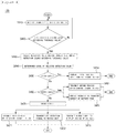
- FIG. 4 is a diagram schematically illustrating an algorithm performed in the control unit.
- control unit may receive a detection value from each detecting unit (S410), and compare the received detection value with a predetermined threshold value.
- the threshold value is a threshold value for the quantity of gas branched when the swelling phenomenon is incurred in the battery cell, and may be formed of a set including a carbon monoxide threshold value, a carbon dioxide threshold value, and a methane threshold value, and may be set by a user.
- a carbon monoxide detection value is compared with a carbon monoxide threshold value
- a carbon dioxide detection value is compared with a carbon dioxide threshold value
- a methane detection value is compared with a methane threshold value, and only when all of the carbon monoxide detection value, the carbon dioxide detection value, and the methane threshold value exceed the corresponding threshold values, it may be determined that the detection value (set) exceeds the threshold value (set) (S420) .
- the largest detection value among the plurality of detection values is selected (S430), and herein, the size may refer to an average of the carbon monoxide detection value, the carbon dioxide detection value, and the methane detection value.
- a level of the selected detection value may be determined based on a first level, a second level, and a third level which are predetermined with differential ranges. That is, when the size of the selected detection value is included in an alert range, a level of the selected detection value may be determined as the first level, when the size of the selected detection value is included in a danger range, a level of the selected detection value may be determined as the second level, and when the size of the selected detection value is included in a serious range, a level of the selected detection value may be determined as the third level.
- the control unit may transmit a vehicle speed (for example, 80 km or less) control signal corresponding to the first level to the ECU of the vehicle (S451).
- a vehicle speed for example, 80 km or less
- the signal may be transmitted by using controller area network (CAN) communication, but the present invention is not limited thereto, and various schemes of communication, such as ZigBee communication, WiFi, radio frequency (RF) communication, and Bluetooth low energy (BLE) communication, may be applied.
- CAN controller area network
- RF radio frequency
- BLE Bluetooth low energy
- control unit may transmit a vehicle speed (for example, 50 km or less) control signal corresponding to the second level to the ECU of the vehicle (S461).
- vehicle speed for example, 50 km or less
- the quantity of charging current flowing into a battery pack from an external power source may also be controlled by controlling a variable resistor (not illustrated) provided in a connection path of the battery pack and the external power source.
- the configuration may aim to prevent overcharging of the battery pack and minimize the quantity of gas branched from the battery cell.
- the control unit may similarly transmit a vehicle speed (for example, 10 km or less) control signal corresponding to the third level to the ECU of the vehicle (S471), and may transmit an alarm signal to a display device, such as a navigation device and a monitor for a vehicle (S473).
- a vehicle speed for example, 10 km or less
- a display device such as a navigation device and a monitor for a vehicle (S473).
- the alarm may be audio-visually formed, such as a predetermined alarm sound and an alarm message, and may enable a passenger of the vehicle to recognize the incurrence of a swelling phenomenon of the battery cell.
- the control unit may transmit an off operation signal to a switch unit 140 (see FIG. 1 ) provided in the connection path of the battery pack and the external power source.
- the switch unit may be formed of one or more of a field effect transistor and a relay, and the kind of contactor forming the switch unit is not limited, but may be various.
- the predetermined time is a concept securing a minimum vehicle operation, and may be, for example, a time consumed for travelling about 10 km, and sudden blocking of the connection between the battery pack and the external power source may cause an accident in the case of an electric vehicle, so that the configuration may consider such a situation.
- control unit may transmit the off operation signal to the switch unit and simultaneously control an operation of a peripheral apparatus, such as an air-cooling type fan and a water-cooling type cooling value, to be stopped, so that it is possible to prevent power consumption according to unnecessary driving of the peripheral apparatus.
- a peripheral apparatus such as an air-cooling type fan and a water-cooling type cooling value
- control unit 130 may determine a level of the largest detection value among the detection values exceeding the threshold value through the predetermined algorithm, and control an operation of a battery circuit and an operation of the peripheral apparatus based on the corresponding level.
- FIG. 5 is a flowchart illustrating the method of detecting swelling of the battery according to the exemplary embodiment of the present invention.
- each of the plurality of detecting units dispersed inside the battery modules detects gas branched from the battery cell, and provides a result of the detection to the control unit (S510).
- the control unit compares each of the detection values with a threshold value, and determines whether there is the detection value exceeding the threshold value (S520). When the number of detection values exceeding the threshold value is two or more, the control unit selects the largest detection value, and determines a level of the selected detection value according to the size of the selected detection value (S530).
- control unit controls an operation speed of the vehicle, controls the quantity of charging current flowing into the battery pack, controls an operation of the battery circuit, such as a control of an off operation of the switch unit, and controls an operation of the peripheral apparatus based on the level of the selected detection value (S540).
Abstract
Description
- This application claims priority to and the benefit of Korean Patent Application No.
10-2015-0129551 - The present invention relates to a system and a method of detecting swelling of a battery, and particularly, to a system and a method of detecting swelling of a battery, in which detecting units are dispersed inside a battery module to detect gas branched from battery cells, a level is given to the largest detection value among the values that exceed a threshold value according to a size of a detection value, and an operation of a battery circuit, an operation speed of a vehicle, and the like are controlled based on the corresponding level, thereby preventing an accident due to a swelling phenomenon of the battery cell.
- A battery has a characteristic in an easy application according to a product group, excellent preservability, a high energy density, and the like. Further, the battery attracts attention as an energy source for improving an environmentally-friendly characteristic and energy efficiency in that a by-product according to the use of energy is not generated, as well as a primary advantage in that it is possible to decrease the use of fossil fuel.
- Because of this, the battery is universally applied to a portable device, an electric vehicle (EV), and an energy storage system (ESS), and the like, and serves as a basis in various industries and simultaneously provide convenience to everyday life.
- However, the battery may be abnormally driven according to a usage environment, and for example, when a battery is overcharged or a lifetime of the battery is exhausted, a swelling phenomenon and the like of the battery may be caused due to an electrical and chemical action generated inside the battery.
- The swelling phenomenon of the battery may lead to an accident, such as ignition and explosion, as well as shortening of the lifetime of the battery and a decrease in capacity of the battery, so that there is a demand for a stable usage of the battery through careful monitoring and an appropriate control.
- Accordingly, various research and development related to a detection of a swelling phenomenon of the battery and a protection of the battery has been conducted, and for example, a technology for detecting a change in a volume of a battery cell according to swelling by using a pressure measuring means and blocking a current through the detection has been publicly known.
- However, a physical volume expansion of the battery cell is generated only when the swelling of the battery cell considerably progresses, so that it is difficult to detect and respond to the swelling phenomenon of the battery cell at an early stage, and even though a current is blocked, there is a large risk of ignition due to the considerable progress of the swelling.
- As another example, a technology of blocking a current by fracturing a member, such as a bus bar and a tap, by expansive force of the battery cell by the swelling phenomenon is also present.
- However, it is not easy for the technology to respond to the swelling phenomenon of the battery cell at an early stage, and spark generable during the fracturing of some of the members may act as ignition sources, thereby causing another reason for ignition.
- The present invention is conceived to solve the foregoing problems, and an object of the present invention is to provide a system and a method of detecting swelling of a battery, which detect gas branched from a battery cell in real time and determine a level of a detection value, and control a supply of power to a battery module, a current charging quantity, and the like based on the corresponding level, thereby solving a function problem of a battery incurrable due to a swelling phenomenon of the battery cell.
- Further, an object of the present invention is to provide a system and a method of detecting swelling of a battery, which appropriately control an operation speed of a vehicle according to a level of a detection value, as well as a control of an operation of a battery circuit, thereby preventing an accident, such as explosion and ignition of the battery and the vehicle, and securing safety of a passenger of the vehicle.
- Another object of the present invention is to provide a system and a method of detecting swelling of a battery, which when a battery cell is present in an abnormal environment, control an operation of a peripheral apparatus, such as a air-cooling type fan and a water-cooling type cooling valve, to be stopped, thereby preventing power consumption by unnecessary driving of the peripheral apparatus.
- According to an exemplary embodiment of the present invention, a system for detecting swelling of a battery includes: a plurality of detecting units which is provided at one or more battery modules of a battery pack, respectively, and detects gas branched from a battery cell of the battery module; a control unit which selects the largest detection value among the detection values of the respective detecting units, determines a level of the selected detection value according to a size of the selected detection value, and controls an operation of a peripheral apparatus based on the corresponding level; and a switch unit which is provided in a connection path of the battery pack and an external power source and is turned on and off according to a signal of the control unit.
- The detecting units may be dispersed at upper, lower, left, right, front, and rear sides inside the battery module.
- Each of the detecting units may include a carbon monoxide detecting sensor, a carbon dioxide detecting sensor, and a methane detecting sensor.
- The detecting value may be formed as one set of values including a carbon monoxide detection value, a carbon dioxide detection value, and a methane detection value.
- The control unit may compare the detection value of each of the detecting units with a predetermined threshold value, select the largest detection value among the detection values exceeding the threshold values, and determine a level of the selected detection value according to the size of the selected detection value.
- The level of the selected detection value may be determined as one of a first level, a second level, and a third level according to the degree of swelling risk.
- When the level of the selected detection value is determined as one of the first level, the second level, and the third level, the control unit may transmit a vehicle speed control signal based on the corresponding level to an electronic control unit (ECU) of a vehicle.
- When the level of the selected detection value is determined as the third level, the control unit may transmit an off operation signal to the switch unit after a predetermined time elapses.
- When the level of the selected detection value is determined as the third level, the control unit may transmit a predetermined alarm signal to a display device pre-installed in a vehicle.
- When the level of the selected detection value is determined as the second level, the control unit may control the quantity of charging current flowing into the battery pack from the external power source.
- According to another exemplary embodiment of the present invention, a method of detecting swelling of a battery includes: detecting, by a plurality of detecting units provided at one or more battery modules of a battery pack, respectively, gas branched from a battery cell of the battery module; selecting, by a control unit, the largest detection value among the detection values of the respective detecting units, determining a level of the selected detection value according to a size of the selected detection value, and controlling an operation of a peripheral apparatus based on the corresponding level; and being turned on and off, by a switch unit provided in a connection path of the battery pack and an external power source, according to a signal of the control unit.
- The detecting units may be dispersed at upper, lower, left, right, front, and rear sides inside the battery module.
- Each of the detecting units may include a carbon monoxide detecting sensor, a carbon dioxide detecting sensor, and a methane detecting sensor.
- The detecting value may be formed as one set of values including a carbon monoxide detection value, a carbon dioxide detection value, and a methane detection value.
- The controlling may include comparing, by the control unit, the detection value of each of the detecting units with a predetermined threshold value, selecting the largest detection value among the detection values exceeding the threshold values, and determining a level of the selected detection value according to the size of the selected detection value.
- The level of the selected detection value may be determined as one of a first level, a second level, and a third level according to the degree of swelling risk.
- The controlling may include, when the level of the selected detection value is determined as one of the first level, the second level, and the third level, transmitting a vehicle speed control signal based on the corresponding level to an electronic control unit (ECU) of a vehicle.
- The controlling may further include, when the level of the selected detection value is determined as the third level, transmitting an off operation signal to the switch unit after a predetermined time elapses.
- The controlling may further include, when the level of the selected detection value is determined as the third level, transmitting a predetermined alarm signal to a display device pre-installed in a vehicle.
- The controlling may further include, when the level of the selected detection value is determined as the second level, controlling the quantity of charging current flowing into the battery pack from the external power source.
- According to one aspect of the present invention, gas branched from a battery cell is detected in real time and a level is determined according to a size of the detected detection value, and an operation of a battery circuit is controlled based on the corresponding level, thereby decreasing danger of an accident incurrable due to a swelling phenomenon and improving efficiency of an operation of a battery while excluding a simple stop of the operation of the battery.
- In this case, the plurality of detecting units detecting branched gas is dispersed inside the battery modules, respectively, so that it is possible to improve sensitivity of a detection of gas, and partially replace only a corresponding battery module, in which a swelling phenomenon is incurred, among the plurality of battery modules, thereby promoting convenience of maintenance and repair and decreasing costs.
- Further, a speed of an operated vehicle is controlled by using a battery as driving energy according to a level of a detection value, thereby preventing an accident incurrable due to an overspeeding operation and securing safety of a passenger of a vehicle when the swelling of the battery cell is incurred.
- Further, when the swelling phenomenon is incurred, a supply of power to a battery pack is stopped and an operation of a peripheral apparatus, such as an air-cooling type fan and a water-cooling type cooling value, is stopped, thereby preventing power consumption by unnecessary driving of the peripheral apparatus.
-
-
FIG. 1 is a diagram schematically illustrating an electric vehicle, to which a system and a method of detecting swelling of a battery according to an exemplary embodiment of the present invention are applicable. -
FIG. 2 is a diagram schematically illustrating a circuit diagram of the system for detecting swelling of the battery according to the exemplary embodiment of the present invention. -
FIG. 3 is a diagram schematically illustrating the case where detecting units of the system for detecting swelling of the battery are provided inside a battery module according to the exemplary embodiment of the present invention. -
FIG. 4 is a diagram schematically illustrating an algorithm performed in a control unit of the system for detecting swelling of the battery according to the exemplary embodiment of the present invention. -
FIG. 5 is a flowchart illustrating the method of detecting swelling of the battery according to the exemplary embodiment of the present invention. - The present invention will be described in detail below with reference to the accompanying drawings. Herein, repeated descriptions and the detailed description of a publicly known function and configuration that may make the gist of the present invention unnecessarily ambiguous will be omitted. Exemplary embodiments of the present invention are provided so as to more completely explain the present invention to those skilled in the art. Accordingly, the shape, the size, etc., of elements in the figures may be exaggerated for a more clear explanation.
- Throughout the specification, unless explicitly described to the contrary, the word "include/comprise" and variations such as "includes/comprises" or "including/comprising" mean further including other constituent elements, not excluding the other constituent elements.
- In addition, the term "... unit" described in the specification means a unit for processing at least one function and operation and may be implemented by hardware components or software components and combinations thereof.
-
FIG. 1 is a diagram schematically illustrating anelectric vehicle 1, to which a system and a method of detecting swelling of a battery according to an exemplary embodiment of the present invention are applicable. - However, the system and the method of detecting swelling of the battery according to the exemplary embodiment of the present invention are applicable to various technical fields, to which a battery is applied, in addition to the
electric vehicle 1. - Referring to
FIG. 1 , theelectric vehicle 1 may include abattery 10, a battery management system (BMS) 20, an electronic control unit (ECU) 30, aninverter 40, and amotor 50. - The
battery 10 is an electric energy source providing driving force to themotor 50 and driving theelectric vehicle 1, and may be charged or discharged by theinverter 40 according to the driving of themotor 50 and/or an internal combustion engine (not illustrated). - The
BMS 20 may estimate a state of thebattery 10 and control a charging/discharging current of thebattery 10 by using information about the state, and further control an opening/closing operation of a contactor. - The ECU 30 is an electronic control apparatus controlling a state of the
electric vehicle 1, and for example, may determine a degree of torque based on information about an accelerator, a break, a speed, and the like, and control an output of the motor to correspond to the torque information. - The
inverter 40 may charge or discharge thebattery 10 based on a control signal of theECU 30, and themotor 50 may drive theelectric vehicle 1 based on electric energy of thebattery 10 and the control information transmitted from theECU 30. - As described above, in the
electric vehicle 1, thebattery 10 is a core element providing driving force, and when thebattery 10 is in an abnormal state, this may cause a failure of theelectric vehicle 1 and various accidents. - For example, when the
battery 10 is present in an environment, such as overcharging and a short-circuit, or a lifetime of thebattery 10 is completely exhausted, gas is generated inside thebattery 10 due to an electrical and chemical reaction to increase internal pressure of thebattery 10, and this may lead to a swelling phenomenon of thebattery 10 which may cause an accident, such as an explosion and ignition. - Accordingly, the monitoring of a state of the
battery 10 and an appropriate protection of thebattery 10 according to a situation are the important matters for stably operating thebattery 10 and are preparations for preventing various accidents due to abnormal driving of thebattery 10 and securing safety of a passenger, and hereinafter, the system and the method of detecting swelling of the battery according to the exemplary embodiment of the present invention will be described with reference toFIGS. 2 to 5 . -
FIG. 2 is a diagram schematically illustrating a circuit diagram of thesystem 100 for detecting swelling of the battery according to the exemplary embodiment of the present invention. - Referring to
FIG. 2 , thesystem 100 for detecting swelling of the battery according to the exemplary embodiment of the present invention may include a plurality of detectingunits 120, acontrol unit 130, and aswitch unit 140. - However, the
system 100 for detecting the swelling of the battery illustrated inFIG. 2 is an exemplary embodiment, and constituent elements thereof are not limited to the exemplary embodiment illustrated inFIG. 2 , and it is noted that some constituent elements may be added, changed, or removed as necessary. - Further, the battery which is described below is a concept including one or more battery packs 110, and it is noted that each of the battery packs 110 also includes one or
more battery modules 111, and similarly, each of thebattery modules 111 includes one ormore battery cells 112. - First, when a swelling phenomenon is incurred in a
predetermined battery cell 112 among the one ormore battery cells 112, the detectingunit 120 may detect branched gas. - In this case, the plurality of detecting
units 120 may be dispersed at upper, lower, left, right, front, and rear sides inside thebattery module 111 as illustrated inFIG. 3 , and the plurality of detectingunits 120 is dispersed for the purpose of preventing a detection error generable when the single detectingunit 120 is provided, and simultaneously improving sensitivity of the detection of gas. - Typically, when a swelling phenomenon is incurred in the battery cell, main ingredients of the branched gas are carbon monoxide, carbon dioxide, methane, and the like, so that each of the detecting
units 120 may include a carbon monoxide detecting sensor, a carbon dioxide detecting sensor, and a methane detecting sensor based on the main ingredients of the branched gas. - Accordingly, detection values measured by the detecting
units 120, respectively, may be formed as one set of values including a carbon monoxide detection value, a carbon dioxide detection value, and a methane detection value, and each set of the detection values may be provided to thecontrol unit 130 which is to be described below through an electrical or communicational route. - The
control unit 130 may receive the detection values, particularly, the sets of detection values including the carbon monoxide detection value, the carbon dioxide detection value, and the methane detection value, from the detectingunits 120, and select a specific detection value set and determine a level of the detection value. Further, thecontrol unit 130 may also control an operation of the peripheral apparatus based on the level of the selected detection value. - In this case, the level of the selected detection value may be determined with one of the plurality of level set with differential ranges based on a degree of swelling risk of the
battery cell 112, and for example, the plurality of levels may include a first level, in which the degree of swelling is an alert level, a second level, in which the degree of swelling of thebattery cell 112 is a danger level, and a third level, in which the degree of swelling is a serious level. - The
control unit 130 may be implemented with the BMS 20 (seeFIG. 1 ) itself, or may be implemented while being included in the BMS, and an algorithm for performing an operation of thecontrol unit 130 may be set in thecontrol unit 130. - The performance of the operation of the
control unit 130 will be described in more detail with reference toFIG. 4 . -
FIG. 4 is a diagram schematically illustrating an algorithm performed in the control unit. - Reviewing each operation of the algorithm, first, the control unit may receive a detection value from each detecting unit (S410), and compare the received detection value with a predetermined threshold value.
- Here, the threshold value is a threshold value for the quantity of gas branched when the swelling phenomenon is incurred in the battery cell, and may be formed of a set including a carbon monoxide threshold value, a carbon dioxide threshold value, and a methane threshold value, and may be set by a user.
- That is, in the comparison operation, a carbon monoxide detection value is compared with a carbon monoxide threshold value, a carbon dioxide detection value is compared with a carbon dioxide threshold value, and similarly, a methane detection value is compared with a methane threshold value, and only when all of the carbon monoxide detection value, the carbon dioxide detection value, and the methane threshold value exceed the corresponding threshold values, it may be determined that the detection value (set) exceeds the threshold value (set) (S420) .
- When the number of detection values exceeding the threshold value is two or more, the largest detection value among the plurality of detection values is selected (S430), and herein, the size may refer to an average of the carbon monoxide detection value, the carbon dioxide detection value, and the methane detection value.
- Sequentially, a level of the selected detection value may be determined based on a first level, a second level, and a third level which are predetermined with differential ranges. That is, when the size of the selected detection value is included in an alert range, a level of the selected detection value may be determined as the first level, when the size of the selected detection value is included in a danger range, a level of the selected detection value may be determined as the second level, and when the size of the selected detection value is included in a serious range, a level of the selected detection value may be determined as the third level.
- When the level of the selected detection value is determined as the first level (S450), the control unit may transmit a vehicle speed (for example, 80 km or less) control signal corresponding to the first level to the ECU of the vehicle (S451).
- In this case, the signal may be transmitted by using controller area network (CAN) communication, but the present invention is not limited thereto, and various schemes of communication, such as ZigBee communication, WiFi, radio frequency (RF) communication, and Bluetooth low energy (BLE) communication, may be applied.
- Even when the level of the selected detection value is determined as the second level (S460), the control unit may transmit a vehicle speed (for example, 50 km or less) control signal corresponding to the second level to the ECU of the vehicle (S461).
- Further, the quantity of charging current flowing into a battery pack from an external power source may also be controlled by controlling a variable resistor (not illustrated) provided in a connection path of the battery pack and the external power source. The configuration may aim to prevent overcharging of the battery pack and minimize the quantity of gas branched from the battery cell.
- Last, when the level of the selected detection value is determined as the third level (S470), the control unit may similarly transmit a vehicle speed (for example, 10 km or less) control signal corresponding to the third level to the ECU of the vehicle (S471), and may transmit an alarm signal to a display device, such as a navigation device and a monitor for a vehicle (S473).
- In this case, the alarm may be audio-visually formed, such as a predetermined alarm sound and an alarm message, and may enable a passenger of the vehicle to recognize the incurrence of a swelling phenomenon of the battery cell.
- Particularly, when the level of the selected detection value is determined as the third level, after a predetermined time elapses, the control unit may transmit an off operation signal to a switch unit 140 (see
FIG. 1 ) provided in the connection path of the battery pack and the external power source. - Herein, the switch unit may be formed of one or more of a field effect transistor and a relay, and the kind of contactor forming the switch unit is not limited, but may be various.
- Further, the predetermined time is a concept securing a minimum vehicle operation, and may be, for example, a time consumed for travelling about 10 km, and sudden blocking of the connection between the battery pack and the external power source may cause an accident in the case of an electric vehicle, so that the configuration may consider such a situation.
- Further, the control unit may transmit the off operation signal to the switch unit and simultaneously control an operation of a peripheral apparatus, such as an air-cooling type fan and a water-cooling type cooling value, to be stopped, so that it is possible to prevent power consumption according to unnecessary driving of the peripheral apparatus.
- As described above, the
control unit 130 may determine a level of the largest detection value among the detection values exceeding the threshold value through the predetermined algorithm, and control an operation of a battery circuit and an operation of the peripheral apparatus based on the corresponding level. -
FIG. 5 is a flowchart illustrating the method of detecting swelling of the battery according to the exemplary embodiment of the present invention. - When the method of detecting swelling of the battery according to the exemplary embodiment of the present invention starts, each of the plurality of detecting units dispersed inside the battery modules detects gas branched from the battery cell, and provides a result of the detection to the control unit (S510).
- The control unit compares each of the detection values with a threshold value, and determines whether there is the detection value exceeding the threshold value (S520). When the number of detection values exceeding the threshold value is two or more, the control unit selects the largest detection value, and determines a level of the selected detection value according to the size of the selected detection value (S530).
- Then, the control unit controls an operation speed of the vehicle, controls the quantity of charging current flowing into the battery pack, controls an operation of the battery circuit, such as a control of an off operation of the switch unit, and controls an operation of the peripheral apparatus based on the level of the selected detection value (S540).
- In the forgoing, the specific exemplary embodiment of the present invention has been illustrated and described, but it is apparent to those skilled in the art that the technical spirit of the present invention is not limited by the accompanying drawings and the described contents, and may be modified in various forms without departing from the spirit of the present invention, and the modifications are considered to belong to the claims of the present invention without departing from the spirit of the present invention.
Claims (18)
- A system for detecting swelling of a battery, the system comprising:a plurality of detecting units which is provided at one or more battery modules of a battery pack, respectively, and detects gas branched from a battery cell of the battery module;a control unit which selects the largest detection value among the detection values of the respective detecting units, determines a level of the selected detection value according to a size of the selected detection value, and controls an operation of a peripheral apparatus based on the corresponding level; anda switch unit which is provided in a connection path of the battery pack and an external power source and is turned on and off according to a signal of the control unit.
- The system of claim 1, wherein the detecting units are dispersed at upper, lower, left, right, front, and rear sides inside the battery module.
- The system of claim 1, wherein each of the detecting units includes a carbon monoxide detecting sensor, a carbon dioxide detecting sensor, and a methane detecting sensor, and
the detecting value is formed as one set of values including a carbon monoxide detection value, a carbon dioxide detection value, and a methane detection value. - The system of claim 1, wherein the control unit compares the detection value of each of the detecting units with a predetermined threshold value, selects the largest detection value among the detection values exceeding the threshold values, and determines a level of the selected detection value according to the size of the selected detection value.
- The system of claim 4, wherein the level of the selected detection value is determined as one of a first level, a second level, and a third level according to the degree of swelling risk.
- The system of claim 5, wherein when the level of the selected detection value is determined as one of the first level, the second level, and the third level, the control unit transmits a vehicle speed control signal based on the corresponding level to an electronic control unit (ECU) of a vehicle.
- The system of claim 5, wherein when the level of the selected detection value is determined as the third level, the control unit transmits an off operation signal to the switch unit after a predetermined time elapses.
- The system of claim 5, wherein when the level of the selected detection value is determined as the third level, the control unit transmits a predetermined alarm signal to a display device pre-installed in a vehicle.
- The system of claim 5, wherein when the level of the selected detection value is determined as the second level, the control unit controls the quantity of charging current flowing into the battery pack from the external power source.
- A method of detecting swelling of a battery, the method comprising:detecting, by a plurality of detecting units provided at one or more battery modules of a battery pack, respectively, gas branched from a battery cell of the battery module;selecting, by a control unit, the largest detection value among the detection values of the respective detecting units, determining a level of the selected detection value according to a size of the selected detection value, and controlling an operation of a peripheral apparatus based on the corresponding level; andbeing turned on and off, by a switch unit provided in a connection path of the battery pack and an external power source, according to a signal of the control unit.
- The method of claim 10, wherein the detecting units are dispersed at upper, lower, left, right, front, and rear sides inside the battery module.
- The method of claim 10, wherein each of the detecting units includes a carbon monoxide detecting sensor, a carbon dioxide detecting sensor, and a methane detecting sensor, and
the detecting value is formed as one set of values including a carbon monoxide detection value, a carbon dioxide detection value, and a methane detection value. - The method of claim 10, wherein the controlling includes comparing, by the control unit, the detection value of each of the detecting units with a predetermined threshold value, selecting the largest detection value among the detection values exceeding the threshold values, and determining a level of the selected detection value according to the size of the selected detection value.
- The method of claim 13, wherein the level of the selected detection value is determined as one of a first level, a second level, and a third level according to the degree of swelling risk.
- The method of claim 14, wherein the controlling includes, when the level of the selected detection value is determined as one of the first level, the second level, and the third level, transmitting a vehicle speed control signal based on the corresponding level to an electronic control unit (ECU) of a vehicle.
- The method of claim 14, wherein the controlling further includes, when the level of the selected detection value is determined as the third level, transmitting an off operation signal to the switch unit after a predetermined time elapses.
- The method of claim 14, wherein the controlling further includes, when the level of the selected detection value is determined as the third level, transmitting a predetermined alarm signal to a display device pre-installed in a vehicle.
- The method of claim 14, wherein the controlling further includes, when the level of the selected detection value is determined as the second level, controlling the quantity of charging current flowing into the battery pack from the external power source.
Priority Applications (1)
| Application Number | Priority Date | Filing Date | Title |
|---|---|---|---|
| PL16846758T PL3300162T3 (en) | 2015-09-14 | 2016-08-18 | Battery swelling sensing system and method |
Applications Claiming Priority (2)
| Application Number | Priority Date | Filing Date | Title |
|---|---|---|---|
| KR1020150129551A KR101942908B1 (en) | 2015-09-14 | 2015-09-14 | System and method for detecting battery swelling |
| PCT/KR2016/009091 WO2017047937A1 (en) | 2015-09-14 | 2016-08-18 | Battery swelling sensing system and method |
Publications (3)
| Publication Number | Publication Date |
|---|---|
| EP3300162A1 true EP3300162A1 (en) | 2018-03-28 |
| EP3300162A4 EP3300162A4 (en) | 2018-06-06 |
| EP3300162B1 EP3300162B1 (en) | 2020-01-29 |
Family
ID=58289074
Family Applications (1)
| Application Number | Title | Priority Date | Filing Date |
|---|---|---|---|
| EP16846758.7A Active EP3300162B1 (en) | 2015-09-14 | 2016-08-18 | Battery swelling sensing system and method |
Country Status (7)
| Country | Link |
|---|---|
| US (1) | US10479213B2 (en) |
| EP (1) | EP3300162B1 (en) |
| JP (1) | JP6409140B2 (en) |
| KR (1) | KR101942908B1 (en) |
| CN (1) | CN107810574B (en) |
| PL (1) | PL3300162T3 (en) |
| WO (1) | WO2017047937A1 (en) |
Cited By (2)
| Publication number | Priority date | Publication date | Assignee | Title |
|---|---|---|---|---|
| EP3605717A4 (en) * | 2017-11-17 | 2020-07-01 | LG Chem, Ltd. | Jig for pressing gas analysis monocell, and gas analysis device including same |
| IT201900001735A1 (en) * | 2019-02-06 | 2020-08-06 | Leonardo Spa | AUXILIARY SAFETY SYSTEM FOR A MODULAR BATTERY IN AN UNDERWATER VEHICLE AND ITS BATTERY |
Families Citing this family (21)
| Publication number | Priority date | Publication date | Assignee | Title |
|---|---|---|---|---|
| US10319207B1 (en) | 2017-02-02 | 2019-06-11 | Briggs & Stratton Corporation | Portable generator including carbon monoxide detector |
| US11028786B2 (en) | 2017-03-28 | 2021-06-08 | Briggs & Stratton, Llc | Portable generator including carbon monoxide detector |
| US11067556B1 (en) | 2017-05-30 | 2021-07-20 | Briggs & Stratton, Llc | Carbon monoxide sensor for portable generator |
| WO2020111899A1 (en) * | 2018-11-30 | 2020-06-04 | 주식회사 엘지화학 | Switch control device and method |
| KR102299116B1 (en) | 2019-09-06 | 2021-09-07 | 인셀(주) | Battery protection method and apparatus using integrated environment monitoring system |
| KR102051810B1 (en) | 2019-09-06 | 2019-12-04 | 인셀(주) | Battery protection method and apparatus using integrated environment monitoring system |
| KR102051809B1 (en) | 2019-09-06 | 2019-12-04 | 인셀(주) | Battery Protection apparatus and Method Using Gas Sensors |
| CN111030185B (en) * | 2019-12-30 | 2023-04-14 | 浙江涌原新能科技股份有限公司 | Multi-stage power utilization control system based on Internet |
| US11177516B2 (en) | 2020-01-10 | 2021-11-16 | Ford Global Technologies, Llc | Thermal event mitigation for battery packs |
| US11239506B2 (en) | 2020-01-10 | 2022-02-01 | Ford Global Technologies, Llc | Thermal event detection for battery packs |
| KR102116720B1 (en) * | 2020-01-20 | 2020-05-29 | (주)테스 | Electrical energy storage system and method for preventing fire thereof |
| KR20210136632A (en) | 2020-05-08 | 2021-11-17 | 에스케이이노베이션 주식회사 | Battery cell anomaly detection system |
| KR20210150072A (en) * | 2020-06-03 | 2021-12-10 | 주식회사 엘지에너지솔루션 | Apparatus and method for battery cell pressure measuring |
| US11636870B2 (en) | 2020-08-20 | 2023-04-25 | Denso International America, Inc. | Smoking cessation systems and methods |
| US11760170B2 (en) | 2020-08-20 | 2023-09-19 | Denso International America, Inc. | Olfaction sensor preservation systems and methods |
| US11760169B2 (en) | 2020-08-20 | 2023-09-19 | Denso International America, Inc. | Particulate control systems and methods for olfaction sensors |
| US11828210B2 (en) | 2020-08-20 | 2023-11-28 | Denso International America, Inc. | Diagnostic systems and methods of vehicles using olfaction |
| US11813926B2 (en) | 2020-08-20 | 2023-11-14 | Denso International America, Inc. | Binding agent and olfaction sensor |
| US11881093B2 (en) | 2020-08-20 | 2024-01-23 | Denso International America, Inc. | Systems and methods for identifying smoking in vehicles |
| US11932080B2 (en) | 2020-08-20 | 2024-03-19 | Denso International America, Inc. | Diagnostic and recirculation control systems and methods |
| EP4083580A1 (en) | 2021-04-30 | 2022-11-02 | Heraeus Nexensos GmbH | Sensor unit for detecting gas flows in a battery block or in a battery unit, battery block, battery unit and method for detecting gas flow in a battery block or in a battery unit |
Family Cites Families (17)
| Publication number | Priority date | Publication date | Assignee | Title |
|---|---|---|---|---|
| JPH10199577A (en) * | 1997-01-13 | 1998-07-31 | Japan Storage Battery Co Ltd | Storage battery device |
| JP2000123887A (en) * | 1998-10-19 | 2000-04-28 | Nikkiso Co Ltd | Abnormality warning device in lithium ion secondary battery |
| JP4083652B2 (en) * | 2003-09-19 | 2008-04-30 | 本田技研工業株式会社 | Gas sensor control device |
| JP4692869B2 (en) | 2003-10-24 | 2011-06-01 | トヨタ自動車株式会社 | Abnormality detection device for fuel cell system |
| KR100670442B1 (en) * | 2005-11-29 | 2007-01-16 | 삼성에스디아이 주식회사 | Battery pack |
| JP2009266563A (en) * | 2008-04-24 | 2009-11-12 | Toyota Motor Corp | Energy storage device |
| KR20090131573A (en) | 2008-06-18 | 2009-12-29 | 현대자동차주식회사 | Current interrupt device when battery is over-charged |
| JP5365079B2 (en) * | 2008-07-07 | 2013-12-11 | トヨタ自動車株式会社 | Detection device and power storage device |
| DE102008043789A1 (en) * | 2008-11-17 | 2010-05-20 | Robert Bosch Gmbh | battery module |
| KR101393223B1 (en) * | 2008-12-19 | 2014-05-08 | 주식회사 엘지화학 | Method of manufacturing lithium second battery and the lithium second battery |
| US9088054B2 (en) | 2009-09-09 | 2015-07-21 | Panacis Inc. | Sensor system and method to prevent battery flaming in overcharge |
| US8877370B2 (en) * | 2010-11-12 | 2014-11-04 | Samsung Sdi Co., Ltd. | Battery pack having a sensor a gas sensor in the cap assembly |
| DE102011016527A1 (en) * | 2011-04-08 | 2012-10-11 | Daimler Ag | Apparatus and method for leak detection of an electrochemical energy storage device |
| EP2645527A1 (en) * | 2012-03-26 | 2013-10-02 | Samsung SDI Co., Ltd. | Battery pack |
| TW201349627A (en) * | 2012-05-31 | 2013-12-01 | Emerald Battery Technologies Co Ltd | Battery monitoring and protection device and system and method thereof |
| KR101583873B1 (en) | 2013-10-22 | 2016-01-08 | 현대자동차주식회사 | Apparatus for preventing over charging of battery and battery comprising the same |
| KR101575449B1 (en) * | 2014-02-18 | 2015-12-07 | 현대자동차주식회사 | System and method for preventing inflow of electrolyte gas |
-
2015
- 2015-09-14 KR KR1020150129551A patent/KR101942908B1/en active IP Right Grant
-
2016
- 2016-08-18 JP JP2017563071A patent/JP6409140B2/en active Active
- 2016-08-18 CN CN201680036163.2A patent/CN107810574B/en active Active
- 2016-08-18 EP EP16846758.7A patent/EP3300162B1/en active Active
- 2016-08-18 PL PL16846758T patent/PL3300162T3/en unknown
- 2016-08-18 WO PCT/KR2016/009091 patent/WO2017047937A1/en active Application Filing
- 2016-08-18 US US15/579,730 patent/US10479213B2/en active Active
Cited By (5)
| Publication number | Priority date | Publication date | Assignee | Title |
|---|---|---|---|---|
| EP3605717A4 (en) * | 2017-11-17 | 2020-07-01 | LG Chem, Ltd. | Jig for pressing gas analysis monocell, and gas analysis device including same |
| US11567048B2 (en) | 2017-11-17 | 2023-01-31 | Lg Energy Solution, Ltd. | Jig for pressing gas analysis monocell, and gas analysis device including same |
| IT201900001735A1 (en) * | 2019-02-06 | 2020-08-06 | Leonardo Spa | AUXILIARY SAFETY SYSTEM FOR A MODULAR BATTERY IN AN UNDERWATER VEHICLE AND ITS BATTERY |
| EP3694045A1 (en) * | 2019-02-06 | 2020-08-12 | LEONARDO S.p.A. | Safety auxiliary system for a modular battery in an underwater vehicle and corresponding battery |
| US11476537B2 (en) | 2019-02-06 | 2022-10-18 | Leonardo S.P.A. | Safety auxiliary system for a modular battery in an underwater vehicle and corresponding battery |
Also Published As
| Publication number | Publication date |
|---|---|
| EP3300162A4 (en) | 2018-06-06 |
| CN107810574A (en) | 2018-03-16 |
| EP3300162B1 (en) | 2020-01-29 |
| WO2017047937A1 (en) | 2017-03-23 |
| KR101942908B1 (en) | 2019-04-17 |
| US20180208074A1 (en) | 2018-07-26 |
| JP6409140B2 (en) | 2018-10-17 |
| JP2018523264A (en) | 2018-08-16 |
| CN107810574B (en) | 2020-05-19 |
| PL3300162T3 (en) | 2020-10-19 |
| US10479213B2 (en) | 2019-11-19 |
| KR20170031940A (en) | 2017-03-22 |
Similar Documents
| Publication | Publication Date | Title |
|---|---|---|
| EP3300162B1 (en) | Battery swelling sensing system and method | |
| EP3232502B1 (en) | System and method for sensing battery cell swelling | |
| US8655535B2 (en) | Electric vehicle and method for controlling same | |
| KR20190012981A (en) | Apparatus for managing battery and battery pack including the same | |
| US9276406B2 (en) | Control device for power supply circuit | |
| KR101855092B1 (en) | Relay control signal independent monitoring apparatus and method | |
| CN101162844A (en) | Battery management system for vehicles | |
| KR20120134611A (en) | Secondary battery sub unit, secondary battery management system and method for exchanging information in multi-pack parallel structure using the same | |
| KR101075037B1 (en) | Battery management system | |
| KR20150098554A (en) | Apparatus, system and method for preventing damage of battery rack using voltage measurement | |
| JPWO2014057538A1 (en) | In-vehicle power storage device and control method thereof | |
| JP2024026100A (en) | Battery condition prediction device and battery condition prediction method | |
| TWI482714B (en) | Parallel-connection battery control system for electric vehicle | |
| KR20180008215A (en) | Battery cell temperature control system and method | |
| KR20110019970A (en) | The system and method for preventing from over-charge or over-discharge of battery | |
| JP6152814B2 (en) | Battery monitoring device | |
| KR20180045092A (en) | System for processing fault information of vehicle | |
| KR101744710B1 (en) | Apparatus and method for discharging battery | |
| KR20210053103A (en) | Appratus and method for monitoring battery | |
| JP2018505639A (en) | Battery pack protection system and method | |
| CN109038756B (en) | Battery pack control method, device and system and battery pack | |
| CN103568854A (en) | Electric car battery parallel-connection control system | |
| RU2803357C1 (en) | Battery protection device and method of its operation | |
| RU2802196C1 (en) | Battery protection device and method | |
| CN111137174A (en) | Method for controlling battery system of electric vehicle |
Legal Events
| Date | Code | Title | Description |
|---|---|---|---|
| STAA | Information on the status of an ep patent application or granted ep patent |
Free format text: STATUS: THE INTERNATIONAL PUBLICATION HAS BEEN MADE |
|
| PUAI | Public reference made under article 153(3) epc to a published international application that has entered the european phase |
Free format text: ORIGINAL CODE: 0009012 |
|
| STAA | Information on the status of an ep patent application or granted ep patent |
Free format text: STATUS: REQUEST FOR EXAMINATION WAS MADE |
|
| 17P | Request for examination filed |
Effective date: 20171220 |
|
| AK | Designated contracting states |
Kind code of ref document: A1 Designated state(s): AL AT BE BG CH CY CZ DE DK EE ES FI FR GB GR HR HU IE IS IT LI LT LU LV MC MK MT NL NO PL PT RO RS SE SI SK SM TR |
|
| AX | Request for extension of the european patent |
Extension state: BA ME |
|
| A4 | Supplementary search report drawn up and despatched |
Effective date: 20180509 |
|
| RIC1 | Information provided on ipc code assigned before grant |
Ipc: H01M 10/48 20060101AFI20180503BHEP Ipc: H01M 2/34 20060101ALI20180503BHEP Ipc: B60L 11/18 20060101ALI20180503BHEP Ipc: H01M 10/42 20060101ALI20180503BHEP |
|
| DAV | Request for validation of the european patent (deleted) | ||
| DAX | Request for extension of the european patent (deleted) | ||
| STAA | Information on the status of an ep patent application or granted ep patent |
Free format text: STATUS: EXAMINATION IS IN PROGRESS |
|
| 17Q | First examination report despatched |
Effective date: 20190131 |
|
| REG | Reference to a national code |
Ref country code: DE Ref legal event code: R079 Ref document number: 602016028959 Country of ref document: DE Free format text: PREVIOUS MAIN CLASS: H01M0010480000 Ipc: H01M0002340000 |
|
| GRAP | Despatch of communication of intention to grant a patent |
Free format text: ORIGINAL CODE: EPIDOSNIGR1 |
|
| RIC1 | Information provided on ipc code assigned before grant |
Ipc: G01N 33/00 20060101ALN20190909BHEP Ipc: H01M 10/48 20060101ALI20190909BHEP Ipc: B60L 3/00 20190101ALI20190909BHEP Ipc: B60L 58/21 20190101ALI20190909BHEP Ipc: H01M 2/34 20060101AFI20190909BHEP |
|
| STAA | Information on the status of an ep patent application or granted ep patent |
Free format text: STATUS: GRANT OF PATENT IS INTENDED |
|
| RIC1 | Information provided on ipc code assigned before grant |
Ipc: H01M 2/34 20060101AFI20190916BHEP Ipc: H01M 10/48 20060101ALI20190916BHEP Ipc: G01N 33/00 20060101ALN20190916BHEP Ipc: B60L 3/00 20190101ALI20190916BHEP Ipc: B60L 58/21 20190101ALI20190916BHEP |
|
| RIC1 | Information provided on ipc code assigned before grant |
Ipc: B60L 3/00 20190101ALI20190930BHEP Ipc: G01N 33/00 20060101ALN20190930BHEP Ipc: H01M 10/48 20060101ALI20190930BHEP Ipc: B60L 58/21 20190101ALI20190930BHEP Ipc: H01M 2/34 20060101AFI20190930BHEP |
|
| INTG | Intention to grant announced |
Effective date: 20191017 |
|
| GRAS | Grant fee paid |
Free format text: ORIGINAL CODE: EPIDOSNIGR3 |
|
| GRAA | (expected) grant |
Free format text: ORIGINAL CODE: 0009210 |
|
| STAA | Information on the status of an ep patent application or granted ep patent |
Free format text: STATUS: THE PATENT HAS BEEN GRANTED |
|
| AK | Designated contracting states |
Kind code of ref document: B1 Designated state(s): AL AT BE BG CH CY CZ DE DK EE ES FI FR GB GR HR HU IE IS IT LI LT LU LV MC MK MT NL NO PL PT RO RS SE SI SK SM TR |
|
| REG | Reference to a national code |
Ref country code: GB Ref legal event code: FG4D |
|
| REG | Reference to a national code |
Ref country code: CH Ref legal event code: EP |
|
| REG | Reference to a national code |
Ref country code: AT Ref legal event code: REF Ref document number: 1229071 Country of ref document: AT Kind code of ref document: T Effective date: 20200215 |
|
| REG | Reference to a national code |
Ref country code: IE Ref legal event code: FG4D |
|
| REG | Reference to a national code |
Ref country code: DE Ref legal event code: R096 Ref document number: 602016028959 Country of ref document: DE |
|
| REG | Reference to a national code |
Ref country code: NL Ref legal event code: MP Effective date: 20200129 |
|
| PG25 | Lapsed in a contracting state [announced via postgrant information from national office to epo] |
Ref country code: FI Free format text: LAPSE BECAUSE OF FAILURE TO SUBMIT A TRANSLATION OF THE DESCRIPTION OR TO PAY THE FEE WITHIN THE PRESCRIBED TIME-LIMIT Effective date: 20200129 Ref country code: RS Free format text: LAPSE BECAUSE OF FAILURE TO SUBMIT A TRANSLATION OF THE DESCRIPTION OR TO PAY THE FEE WITHIN THE PRESCRIBED TIME-LIMIT Effective date: 20200129 Ref country code: NO Free format text: LAPSE BECAUSE OF FAILURE TO SUBMIT A TRANSLATION OF THE DESCRIPTION OR TO PAY THE FEE WITHIN THE PRESCRIBED TIME-LIMIT Effective date: 20200429 Ref country code: PT Free format text: LAPSE BECAUSE OF FAILURE TO SUBMIT A TRANSLATION OF THE DESCRIPTION OR TO PAY THE FEE WITHIN THE PRESCRIBED TIME-LIMIT Effective date: 20200621 |
|
| REG | Reference to a national code |
Ref country code: LT Ref legal event code: MG4D |
|
| PG25 | Lapsed in a contracting state [announced via postgrant information from national office to epo] |
Ref country code: IS Free format text: LAPSE BECAUSE OF FAILURE TO SUBMIT A TRANSLATION OF THE DESCRIPTION OR TO PAY THE FEE WITHIN THE PRESCRIBED TIME-LIMIT Effective date: 20200529 Ref country code: BG Free format text: LAPSE BECAUSE OF FAILURE TO SUBMIT A TRANSLATION OF THE DESCRIPTION OR TO PAY THE FEE WITHIN THE PRESCRIBED TIME-LIMIT Effective date: 20200429 Ref country code: GR Free format text: LAPSE BECAUSE OF FAILURE TO SUBMIT A TRANSLATION OF THE DESCRIPTION OR TO PAY THE FEE WITHIN THE PRESCRIBED TIME-LIMIT Effective date: 20200430 Ref country code: SE Free format text: LAPSE BECAUSE OF FAILURE TO SUBMIT A TRANSLATION OF THE DESCRIPTION OR TO PAY THE FEE WITHIN THE PRESCRIBED TIME-LIMIT Effective date: 20200129 Ref country code: LV Free format text: LAPSE BECAUSE OF FAILURE TO SUBMIT A TRANSLATION OF THE DESCRIPTION OR TO PAY THE FEE WITHIN THE PRESCRIBED TIME-LIMIT Effective date: 20200129 Ref country code: HR Free format text: LAPSE BECAUSE OF FAILURE TO SUBMIT A TRANSLATION OF THE DESCRIPTION OR TO PAY THE FEE WITHIN THE PRESCRIBED TIME-LIMIT Effective date: 20200129 |
|
| PG25 | Lapsed in a contracting state [announced via postgrant information from national office to epo] |
Ref country code: NL Free format text: LAPSE BECAUSE OF FAILURE TO SUBMIT A TRANSLATION OF THE DESCRIPTION OR TO PAY THE FEE WITHIN THE PRESCRIBED TIME-LIMIT Effective date: 20200129 |
|
| PG25 | Lapsed in a contracting state [announced via postgrant information from national office to epo] |
Ref country code: ES Free format text: LAPSE BECAUSE OF FAILURE TO SUBMIT A TRANSLATION OF THE DESCRIPTION OR TO PAY THE FEE WITHIN THE PRESCRIBED TIME-LIMIT Effective date: 20200129 Ref country code: DK Free format text: LAPSE BECAUSE OF FAILURE TO SUBMIT A TRANSLATION OF THE DESCRIPTION OR TO PAY THE FEE WITHIN THE PRESCRIBED TIME-LIMIT Effective date: 20200129 Ref country code: SK Free format text: LAPSE BECAUSE OF FAILURE TO SUBMIT A TRANSLATION OF THE DESCRIPTION OR TO PAY THE FEE WITHIN THE PRESCRIBED TIME-LIMIT Effective date: 20200129 Ref country code: SM Free format text: LAPSE BECAUSE OF FAILURE TO SUBMIT A TRANSLATION OF THE DESCRIPTION OR TO PAY THE FEE WITHIN THE PRESCRIBED TIME-LIMIT Effective date: 20200129 Ref country code: EE Free format text: LAPSE BECAUSE OF FAILURE TO SUBMIT A TRANSLATION OF THE DESCRIPTION OR TO PAY THE FEE WITHIN THE PRESCRIBED TIME-LIMIT Effective date: 20200129 Ref country code: CZ Free format text: LAPSE BECAUSE OF FAILURE TO SUBMIT A TRANSLATION OF THE DESCRIPTION OR TO PAY THE FEE WITHIN THE PRESCRIBED TIME-LIMIT Effective date: 20200129 Ref country code: RO Free format text: LAPSE BECAUSE OF FAILURE TO SUBMIT A TRANSLATION OF THE DESCRIPTION OR TO PAY THE FEE WITHIN THE PRESCRIBED TIME-LIMIT Effective date: 20200129 Ref country code: LT Free format text: LAPSE BECAUSE OF FAILURE TO SUBMIT A TRANSLATION OF THE DESCRIPTION OR TO PAY THE FEE WITHIN THE PRESCRIBED TIME-LIMIT Effective date: 20200129 |
|
| REG | Reference to a national code |
Ref country code: DE Ref legal event code: R097 Ref document number: 602016028959 Country of ref document: DE |
|
| REG | Reference to a national code |
Ref country code: AT Ref legal event code: MK05 Ref document number: 1229071 Country of ref document: AT Kind code of ref document: T Effective date: 20200129 |
|
| REG | Reference to a national code |
Ref country code: DE Ref legal event code: R079 Ref document number: 602016028959 Country of ref document: DE Free format text: PREVIOUS MAIN CLASS: H01M0002340000 Ipc: H01M0050572000 |
|
| PLBE | No opposition filed within time limit |
Free format text: ORIGINAL CODE: 0009261 |
|
| STAA | Information on the status of an ep patent application or granted ep patent |
Free format text: STATUS: NO OPPOSITION FILED WITHIN TIME LIMIT |
|
| 26N | No opposition filed |
Effective date: 20201030 |
|
| PG25 | Lapsed in a contracting state [announced via postgrant information from national office to epo] |
Ref country code: AT Free format text: LAPSE BECAUSE OF FAILURE TO SUBMIT A TRANSLATION OF THE DESCRIPTION OR TO PAY THE FEE WITHIN THE PRESCRIBED TIME-LIMIT Effective date: 20200129 Ref country code: IT Free format text: LAPSE BECAUSE OF FAILURE TO SUBMIT A TRANSLATION OF THE DESCRIPTION OR TO PAY THE FEE WITHIN THE PRESCRIBED TIME-LIMIT Effective date: 20200129 |
|
| PG25 | Lapsed in a contracting state [announced via postgrant information from national office to epo] |
Ref country code: SI Free format text: LAPSE BECAUSE OF FAILURE TO SUBMIT A TRANSLATION OF THE DESCRIPTION OR TO PAY THE FEE WITHIN THE PRESCRIBED TIME-LIMIT Effective date: 20200129 |
|
| PG25 | Lapsed in a contracting state [announced via postgrant information from national office to epo] |
Ref country code: MC Free format text: LAPSE BECAUSE OF FAILURE TO SUBMIT A TRANSLATION OF THE DESCRIPTION OR TO PAY THE FEE WITHIN THE PRESCRIBED TIME-LIMIT Effective date: 20200129 |
|
| REG | Reference to a national code |
Ref country code: CH Ref legal event code: PL |
|
| PG25 | Lapsed in a contracting state [announced via postgrant information from national office to epo] |
Ref country code: LI Free format text: LAPSE BECAUSE OF NON-PAYMENT OF DUE FEES Effective date: 20200831 Ref country code: LU Free format text: LAPSE BECAUSE OF NON-PAYMENT OF DUE FEES Effective date: 20200818 Ref country code: CH Free format text: LAPSE BECAUSE OF NON-PAYMENT OF DUE FEES Effective date: 20200831 |
|
| REG | Reference to a national code |
Ref country code: BE Ref legal event code: MM Effective date: 20200831 |
|
| PG25 | Lapsed in a contracting state [announced via postgrant information from national office to epo] |
Ref country code: IE Free format text: LAPSE BECAUSE OF NON-PAYMENT OF DUE FEES Effective date: 20200818 Ref country code: BE Free format text: LAPSE BECAUSE OF NON-PAYMENT OF DUE FEES Effective date: 20200831 |
|
| PG25 | Lapsed in a contracting state [announced via postgrant information from national office to epo] |
Ref country code: TR Free format text: LAPSE BECAUSE OF FAILURE TO SUBMIT A TRANSLATION OF THE DESCRIPTION OR TO PAY THE FEE WITHIN THE PRESCRIBED TIME-LIMIT Effective date: 20200129 Ref country code: MT Free format text: LAPSE BECAUSE OF FAILURE TO SUBMIT A TRANSLATION OF THE DESCRIPTION OR TO PAY THE FEE WITHIN THE PRESCRIBED TIME-LIMIT Effective date: 20200129 Ref country code: CY Free format text: LAPSE BECAUSE OF FAILURE TO SUBMIT A TRANSLATION OF THE DESCRIPTION OR TO PAY THE FEE WITHIN THE PRESCRIBED TIME-LIMIT Effective date: 20200129 |
|
| PG25 | Lapsed in a contracting state [announced via postgrant information from national office to epo] |
Ref country code: MK Free format text: LAPSE BECAUSE OF FAILURE TO SUBMIT A TRANSLATION OF THE DESCRIPTION OR TO PAY THE FEE WITHIN THE PRESCRIBED TIME-LIMIT Effective date: 20200129 Ref country code: AL Free format text: LAPSE BECAUSE OF FAILURE TO SUBMIT A TRANSLATION OF THE DESCRIPTION OR TO PAY THE FEE WITHIN THE PRESCRIBED TIME-LIMIT Effective date: 20200129 |
|
| REG | Reference to a national code |
Ref country code: DE Ref legal event code: R081 Ref document number: 602016028959 Country of ref document: DE Owner name: LG ENERGY SOLUTION, LTD., KR Free format text: FORMER OWNER: LG CHEM, LTD., SEOUL, KR |
|
| P01 | Opt-out of the competence of the unified patent court (upc) registered |
Effective date: 20230512 |
|
| REG | Reference to a national code |
Ref country code: GB Ref legal event code: 732E Free format text: REGISTERED BETWEEN 20230824 AND 20230831 |
|
| PGFP | Annual fee paid to national office [announced via postgrant information from national office to epo] |
Ref country code: GB Payment date: 20230720 Year of fee payment: 8 |
|
| PGFP | Annual fee paid to national office [announced via postgrant information from national office to epo] |
Ref country code: PL Payment date: 20230724 Year of fee payment: 8 Ref country code: FR Payment date: 20230725 Year of fee payment: 8 Ref country code: DE Payment date: 20230720 Year of fee payment: 8 |