EP4083580A1 - Sensor unit for detecting gas flows in a battery block or in a battery unit, battery block, battery unit and method for detecting gas flow in a battery block or in a battery unit - Google Patents
Sensor unit for detecting gas flows in a battery block or in a battery unit, battery block, battery unit and method for detecting gas flow in a battery block or in a battery unit Download PDFInfo
- Publication number
- EP4083580A1 EP4083580A1 EP21171467.0A EP21171467A EP4083580A1 EP 4083580 A1 EP4083580 A1 EP 4083580A1 EP 21171467 A EP21171467 A EP 21171467A EP 4083580 A1 EP4083580 A1 EP 4083580A1
- Authority
- EP
- European Patent Office
- Prior art keywords
- resistance temperature
- battery
- temperature sensor
- sensor
- unit
- Prior art date
- Legal status (The legal status is an assumption and is not a legal conclusion. Google has not performed a legal analysis and makes no representation as to the accuracy of the status listed.)
- Pending
Links
- 238000000034 method Methods 0.000 title claims description 16
- 230000008859 change Effects 0.000 claims description 13
- 229910001416 lithium ion Inorganic materials 0.000 claims description 10
- HBBGRARXTFLTSG-UHFFFAOYSA-N Lithium ion Chemical compound [Li+] HBBGRARXTFLTSG-UHFFFAOYSA-N 0.000 claims description 8
- 239000007789 gas Substances 0.000 description 96
- 230000008901 benefit Effects 0.000 description 9
- 238000001816 cooling Methods 0.000 description 9
- 238000001514 detection method Methods 0.000 description 8
- BASFCYQUMIYNBI-UHFFFAOYSA-N platinum Chemical compound [Pt] BASFCYQUMIYNBI-UHFFFAOYSA-N 0.000 description 8
- 239000004020 conductor Substances 0.000 description 6
- 239000000112 cooling gas Substances 0.000 description 5
- 238000013461 design Methods 0.000 description 5
- 230000017525 heat dissipation Effects 0.000 description 5
- 239000000758 substrate Substances 0.000 description 5
- 230000015572 biosynthetic process Effects 0.000 description 4
- 239000000853 adhesive Substances 0.000 description 3
- 230000001070 adhesive effect Effects 0.000 description 3
- 239000012876 carrier material Substances 0.000 description 3
- 238000007599 discharging Methods 0.000 description 3
- 229910052739 hydrogen Inorganic materials 0.000 description 3
- 239000010410 layer Substances 0.000 description 3
- 239000000463 material Substances 0.000 description 3
- 238000012544 monitoring process Methods 0.000 description 3
- 229910052697 platinum Inorganic materials 0.000 description 3
- 230000001105 regulatory effect Effects 0.000 description 3
- 230000004044 response Effects 0.000 description 3
- UFHFLCQGNIYNRP-UHFFFAOYSA-N Hydrogen Chemical compound [H][H] UFHFLCQGNIYNRP-UHFFFAOYSA-N 0.000 description 2
- 230000004913 activation Effects 0.000 description 2
- 239000012790 adhesive layer Substances 0.000 description 2
- 238000001311 chemical methods and process Methods 0.000 description 2
- 230000000875 corresponding effect Effects 0.000 description 2
- 238000011161 development Methods 0.000 description 2
- 238000010438 heat treatment Methods 0.000 description 2
- 239000001257 hydrogen Substances 0.000 description 2
- 238000007373 indentation Methods 0.000 description 2
- 238000005259 measurement Methods 0.000 description 2
- 229910052751 metal Inorganic materials 0.000 description 2
- 239000002184 metal Substances 0.000 description 2
- 238000003199 nucleic acid amplification method Methods 0.000 description 2
- 238000002161 passivation Methods 0.000 description 2
- 230000009467 reduction Effects 0.000 description 2
- 239000000126 substance Substances 0.000 description 2
- 238000012546 transfer Methods 0.000 description 2
- 239000004593 Epoxy Substances 0.000 description 1
- 230000002159 abnormal effect Effects 0.000 description 1
- 230000005856 abnormality Effects 0.000 description 1
- 230000003321 amplification Effects 0.000 description 1
- 238000007630 basic procedure Methods 0.000 description 1
- 229910002091 carbon monoxide Inorganic materials 0.000 description 1
- 238000006243 chemical reaction Methods 0.000 description 1
- 230000005493 condensed matter Effects 0.000 description 1
- 238000010276 construction Methods 0.000 description 1
- 239000002826 coolant Substances 0.000 description 1
- 230000002596 correlated effect Effects 0.000 description 1
- 230000000694 effects Effects 0.000 description 1
- 239000012530 fluid Substances 0.000 description 1
- 229930195733 hydrocarbon Natural products 0.000 description 1
- 150000002430 hydrocarbons Chemical class 0.000 description 1
- 230000002452 interceptive effect Effects 0.000 description 1
- 238000004519 manufacturing process Methods 0.000 description 1
- 239000012528 membrane Substances 0.000 description 1
- 230000002093 peripheral effect Effects 0.000 description 1
- 230000008569 process Effects 0.000 description 1
- 230000000284 resting effect Effects 0.000 description 1
- 230000035945 sensitivity Effects 0.000 description 1
- 238000005245 sintering Methods 0.000 description 1
- 238000005476 soldering Methods 0.000 description 1
- 238000005496 tempering Methods 0.000 description 1
Images


Classifications
-
- G—PHYSICS
- G01—MEASURING; TESTING
- G01F—MEASURING VOLUME, VOLUME FLOW, MASS FLOW OR LIQUID LEVEL; METERING BY VOLUME
- G01F1/00—Measuring the volume flow or mass flow of fluid or fluent solid material wherein the fluid passes through a meter in a continuous flow
- G01F1/68—Measuring the volume flow or mass flow of fluid or fluent solid material wherein the fluid passes through a meter in a continuous flow by using thermal effects
- G01F1/684—Structural arrangements; Mounting of elements, e.g. in relation to fluid flow
- G01F1/688—Structural arrangements; Mounting of elements, e.g. in relation to fluid flow using a particular type of heating, cooling or sensing element
- G01F1/69—Structural arrangements; Mounting of elements, e.g. in relation to fluid flow using a particular type of heating, cooling or sensing element of resistive type
-
- B—PERFORMING OPERATIONS; TRANSPORTING
- B60—VEHICLES IN GENERAL
- B60L—PROPULSION OF ELECTRICALLY-PROPELLED VEHICLES; SUPPLYING ELECTRIC POWER FOR AUXILIARY EQUIPMENT OF ELECTRICALLY-PROPELLED VEHICLES; ELECTRODYNAMIC BRAKE SYSTEMS FOR VEHICLES IN GENERAL; MAGNETIC SUSPENSION OR LEVITATION FOR VEHICLES; MONITORING OPERATING VARIABLES OF ELECTRICALLY-PROPELLED VEHICLES; ELECTRIC SAFETY DEVICES FOR ELECTRICALLY-PROPELLED VEHICLES
- B60L3/00—Electric devices on electrically-propelled vehicles for safety purposes; Monitoring operating variables, e.g. speed, deceleration or energy consumption
- B60L3/0023—Detecting, eliminating, remedying or compensating for drive train abnormalities, e.g. failures within the drive train
- B60L3/0046—Detecting, eliminating, remedying or compensating for drive train abnormalities, e.g. failures within the drive train relating to electric energy storage systems, e.g. batteries or capacitors
-
- B—PERFORMING OPERATIONS; TRANSPORTING
- B60—VEHICLES IN GENERAL
- B60L—PROPULSION OF ELECTRICALLY-PROPELLED VEHICLES; SUPPLYING ELECTRIC POWER FOR AUXILIARY EQUIPMENT OF ELECTRICALLY-PROPELLED VEHICLES; ELECTRODYNAMIC BRAKE SYSTEMS FOR VEHICLES IN GENERAL; MAGNETIC SUSPENSION OR LEVITATION FOR VEHICLES; MONITORING OPERATING VARIABLES OF ELECTRICALLY-PROPELLED VEHICLES; ELECTRIC SAFETY DEVICES FOR ELECTRICALLY-PROPELLED VEHICLES
- B60L50/00—Electric propulsion with power supplied within the vehicle
- B60L50/50—Electric propulsion with power supplied within the vehicle using propulsion power supplied by batteries or fuel cells
- B60L50/60—Electric propulsion with power supplied within the vehicle using propulsion power supplied by batteries or fuel cells using power supplied by batteries
- B60L50/64—Constructional details of batteries specially adapted for electric vehicles
-
- B—PERFORMING OPERATIONS; TRANSPORTING
- B60—VEHICLES IN GENERAL
- B60L—PROPULSION OF ELECTRICALLY-PROPELLED VEHICLES; SUPPLYING ELECTRIC POWER FOR AUXILIARY EQUIPMENT OF ELECTRICALLY-PROPELLED VEHICLES; ELECTRODYNAMIC BRAKE SYSTEMS FOR VEHICLES IN GENERAL; MAGNETIC SUSPENSION OR LEVITATION FOR VEHICLES; MONITORING OPERATING VARIABLES OF ELECTRICALLY-PROPELLED VEHICLES; ELECTRIC SAFETY DEVICES FOR ELECTRICALLY-PROPELLED VEHICLES
- B60L58/00—Methods or circuit arrangements for monitoring or controlling batteries or fuel cells, specially adapted for electric vehicles
- B60L58/10—Methods or circuit arrangements for monitoring or controlling batteries or fuel cells, specially adapted for electric vehicles for monitoring or controlling batteries
- B60L58/24—Methods or circuit arrangements for monitoring or controlling batteries or fuel cells, specially adapted for electric vehicles for monitoring or controlling batteries for controlling the temperature of batteries
- B60L58/26—Methods or circuit arrangements for monitoring or controlling batteries or fuel cells, specially adapted for electric vehicles for monitoring or controlling batteries for controlling the temperature of batteries by cooling
-
- H—ELECTRICITY
- H01—ELECTRIC ELEMENTS
- H01M—PROCESSES OR MEANS, e.g. BATTERIES, FOR THE DIRECT CONVERSION OF CHEMICAL ENERGY INTO ELECTRICAL ENERGY
- H01M10/00—Secondary cells; Manufacture thereof
- H01M10/42—Methods or arrangements for servicing or maintenance of secondary cells or secondary half-cells
- H01M10/48—Accumulators combined with arrangements for measuring, testing or indicating the condition of cells, e.g. the level or density of the electrolyte
-
- H—ELECTRICITY
- H01—ELECTRIC ELEMENTS
- H01M—PROCESSES OR MEANS, e.g. BATTERIES, FOR THE DIRECT CONVERSION OF CHEMICAL ENERGY INTO ELECTRICAL ENERGY
- H01M50/00—Constructional details or processes of manufacture of the non-active parts of electrochemical cells other than fuel cells, e.g. hybrid cells
- H01M50/20—Mountings; Secondary casings or frames; Racks, modules or packs; Suspension devices; Shock absorbers; Transport or carrying devices; Holders
- H01M50/204—Racks, modules or packs for multiple batteries or multiple cells
-
- H—ELECTRICITY
- H01—ELECTRIC ELEMENTS
- H01M—PROCESSES OR MEANS, e.g. BATTERIES, FOR THE DIRECT CONVERSION OF CHEMICAL ENERGY INTO ELECTRICAL ENERGY
- H01M50/00—Constructional details or processes of manufacture of the non-active parts of electrochemical cells other than fuel cells, e.g. hybrid cells
- H01M50/20—Mountings; Secondary casings or frames; Racks, modules or packs; Suspension devices; Shock absorbers; Transport or carrying devices; Holders
- H01M50/258—Modular batteries; Casings provided with means for assembling
-
- H—ELECTRICITY
- H02—GENERATION; CONVERSION OR DISTRIBUTION OF ELECTRIC POWER
- H02J—CIRCUIT ARRANGEMENTS OR SYSTEMS FOR SUPPLYING OR DISTRIBUTING ELECTRIC POWER; SYSTEMS FOR STORING ELECTRIC ENERGY
- H02J7/00—Circuit arrangements for charging or depolarising batteries or for supplying loads from batteries
- H02J7/0029—Circuit arrangements for charging or depolarising batteries or for supplying loads from batteries with safety or protection devices or circuits
- H02J7/00309—Overheat or overtemperature protection
-
- H—ELECTRICITY
- H02—GENERATION; CONVERSION OR DISTRIBUTION OF ELECTRIC POWER
- H02J—CIRCUIT ARRANGEMENTS OR SYSTEMS FOR SUPPLYING OR DISTRIBUTING ELECTRIC POWER; SYSTEMS FOR STORING ELECTRIC ENERGY
- H02J7/00—Circuit arrangements for charging or depolarising batteries or for supplying loads from batteries
- H02J7/007—Regulation of charging or discharging current or voltage
- H02J7/007188—Regulation of charging or discharging current or voltage the charge cycle being controlled or terminated in response to non-electric parameters
- H02J7/00719—Regulation of charging or discharging current or voltage the charge cycle being controlled or terminated in response to non-electric parameters in response to degree of gas development in the battery
-
- H—ELECTRICITY
- H02—GENERATION; CONVERSION OR DISTRIBUTION OF ELECTRIC POWER
- H02J—CIRCUIT ARRANGEMENTS OR SYSTEMS FOR SUPPLYING OR DISTRIBUTING ELECTRIC POWER; SYSTEMS FOR STORING ELECTRIC ENERGY
- H02J7/00—Circuit arrangements for charging or depolarising batteries or for supplying loads from batteries
- H02J7/007—Regulation of charging or discharging current or voltage
- H02J7/007188—Regulation of charging or discharging current or voltage the charge cycle being controlled or terminated in response to non-electric parameters
- H02J7/007192—Regulation of charging or discharging current or voltage the charge cycle being controlled or terminated in response to non-electric parameters in response to temperature
- H02J7/007194—Regulation of charging or discharging current or voltage the charge cycle being controlled or terminated in response to non-electric parameters in response to temperature of the battery
-
- B—PERFORMING OPERATIONS; TRANSPORTING
- B60—VEHICLES IN GENERAL
- B60L—PROPULSION OF ELECTRICALLY-PROPELLED VEHICLES; SUPPLYING ELECTRIC POWER FOR AUXILIARY EQUIPMENT OF ELECTRICALLY-PROPELLED VEHICLES; ELECTRODYNAMIC BRAKE SYSTEMS FOR VEHICLES IN GENERAL; MAGNETIC SUSPENSION OR LEVITATION FOR VEHICLES; MONITORING OPERATING VARIABLES OF ELECTRICALLY-PROPELLED VEHICLES; ELECTRIC SAFETY DEVICES FOR ELECTRICALLY-PROPELLED VEHICLES
- B60L2240/00—Control parameters of input or output; Target parameters
- B60L2240/40—Drive Train control parameters
- B60L2240/54—Drive Train control parameters related to batteries
- B60L2240/545—Temperature
-
- H—ELECTRICITY
- H01—ELECTRIC ELEMENTS
- H01M—PROCESSES OR MEANS, e.g. BATTERIES, FOR THE DIRECT CONVERSION OF CHEMICAL ENERGY INTO ELECTRICAL ENERGY
- H01M10/00—Secondary cells; Manufacture thereof
- H01M10/05—Accumulators with non-aqueous electrolyte
- H01M10/052—Li-accumulators
- H01M10/0525—Rocking-chair batteries, i.e. batteries with lithium insertion or intercalation in both electrodes; Lithium-ion batteries
-
- H—ELECTRICITY
- H01—ELECTRIC ELEMENTS
- H01M—PROCESSES OR MEANS, e.g. BATTERIES, FOR THE DIRECT CONVERSION OF CHEMICAL ENERGY INTO ELECTRICAL ENERGY
- H01M50/00—Constructional details or processes of manufacture of the non-active parts of electrochemical cells other than fuel cells, e.g. hybrid cells
- H01M50/20—Mountings; Secondary casings or frames; Racks, modules or packs; Suspension devices; Shock absorbers; Transport or carrying devices; Holders
- H01M50/249—Mountings; Secondary casings or frames; Racks, modules or packs; Suspension devices; Shock absorbers; Transport or carrying devices; Holders specially adapted for aircraft or vehicles, e.g. cars or trains
Definitions
- the invention relates to a sensor unit for detecting gas flows in a battery block or in a battery unit. Furthermore, the invention relates to a battery pack with a plurality of battery cells located in a housing. Furthermore, the invention relates to a battery unit with a plurality of battery blocks located in a battery unit housing. The invention also relates to a method for detecting gas flows in a battery block or in a battery unit.
- Lithium-ion batteries are currently considered to be storage devices with the highest energy density in relation to available accumulators. For this reason, lithium-ion batteries have been used for some time in mobile devices that are not permanently connected to an electrical network. The desire for ever larger batteries with high performance is increasing. To achieve this, individual lithium-ion cells are connected in series and in series to form battery blocks. However, it is known that short circuits can occur within individual cells during the operation of such battery blocks, which in turn can trigger chain reactions. Such safety-relevant faults, which are referred to as "thermal runaway”, must therefore be recognized early on in order to be able to initiate suitable countermeasures, such as immediately switching off the battery block in question.
- U.S. 2019/0379030 A1 proposes, for example, using a gas sensor to determine concentrations of a gas species, in particular CO 2 , CO, H 2 , O 2 , NO x , O 3 , H 2 O hydrocarbons (CH 4 ), in a gas circulation unit which is part of the battery system , to prove. Furthermore, a method is proposed that initiates countermeasures when abnormal conditions occur.
- a gas species in particular CO 2 , CO, H 2 , O 2 , NO x , O 3 , H 2 O hydrocarbons (CH 4 )
- KR 102 181 521 B proposes a battery module in which a gas cooling fan device is formed in the housing. This gas-cooling fan unit is switched off when it detects gases being released, which are produced when a battery cell is overcharged.
- EP 2 358 432 B1 proposes, however, a battery module that has a monitoring means.
- the concentration of a gas in the tempering fluid inside the battery housing is monitored with the aid of the monitoring means.
- a battery module which has a multiplicity of detection units within the battery module for the detection of gases.
- EP 2 797 158 A1 proposes a battery system consisting of multiple battery sub-units.
- Each battery sub-unit is equipped with a gas leak sensor located in the cooling gas flow outlet area, which detects abnormalities in the gas flow. On the basis of detected anomalies in the gas flow, it can be initiated, for example, that a discharge fan conveys more air volume out of the housing than a supply air fan conveys air volume into the housing.
- a further object of the present invention is to specify a further developed battery unit which is further developed in particular with regard to a sensor unit for detecting gas flows.
- a further object of the present invention is to specify a further developed method for detecting gas flows in a battery block and/or in a battery unit. With the help of a further developed method, a more rapid detection of the "thermal runaway" should be made possible in particular than is possible with previously known methods.
- this object is achieved with regard to a sensor unit by the subject matter of claim 1, with regard to a battery pack by the subject matter of patent claim 7, with regard to a battery unit by the subject matter of patent claim 10, and with regard to a method for detecting gas flows in a battery pack or in a battery unit by the subject matter of claim 13.
- the invention is based on the idea of specifying a sensor unit for detecting gas flows in a battery block or in a battery unit, the sensor unit having a carrier and at least one resistance temperature sensor.
- the at least one resistance temperature sensor has at least six sides, namely an upper side, a lower side and four end faces, with the resistance temperature sensor being connected to the carrier in such a way that the upper side, the lower side and at least two end sides can be flowed around by a gas at least in sections.
- the invention is thus based on the idea of connecting a resistance temperature sensor to a carrier in such a way that a gas can flow around the resistance temperature sensor at least in sections with regard to the upper side, the lower side and at least two end faces.
- top and bottom of a resistance temperature sensor are the sides that point upwards (top) or downwards (bottom) when a sensor unit is placed on an (imaginary) horizontal storage surface.
- the storage takes place in such a way that the carrier of the sensor unit rests on the (imaginary) horizontal storage surface.
- the four end faces are the four additional sides of an essentially cuboid element.
- the four end faces form the four further peripheral sides of a cuboid element.
- the four end faces are formed essentially perpendicularly to the top and to the bottom. Depending on the manufacturing process, there may be corresponding variants with regard to a vertical arrangement.
- the at least one resistance temperature sensor is preferably connected directly or indirectly to the carrier on at most two sections of one side, preferably on the underside.
- the described connection of the resistance temperature sensor to the carrier relates primarily to the structural connection to the carrier.
- the connection relates to the placement of the resistance temperature sensor in relation to the carrier and the mounting.
- the connection does not primarily concern the electrical connection of the RTD to the carrier.
- the structural connection described can also relate to an electrical connection or enable such a combined connection (structural and electrical).
- the resistance temperature sensor is connected to the carrier on at most two sections of one side, preferably on the underside, it is possible for a gas to flow completely around the upper side and the four end faces. Due to the connection of the resistance temperature sensor to the carrier, a gas can flow around the underside at least in sections, preferably predominantly. With such a fastening configuration, a gas can flow completely around the resistance temperature sensor, with the exception of the two sections for connecting the resistance temperature sensor.
- the resistance temperature sensor is connected to the carrier by means of adhesion.
- the resistance temperature sensor can be glued to the carrier.
- the resistance temperature sensor in a further embodiment of the invention it is possible for the resistance temperature sensor to be connected to the carrier by means of a sintered material.
- the connection of the resistance temperature sensor to the carrier it is possible for the connection of the resistance temperature sensor to the carrier to constitute an electrical contact at the same time. It is possible here for the resistance temperature sensor to have at least one, preferably at least two, contact pads. In such an embodiment of the invention, the resistance temperature sensor is preferably designed as a flip-chip sensor. In this case, a resistance temperature sensor has two contact pads on one side, preferably on the underside. The resistance temperature sensors are mechanically and electrically connected, for example, to further contact pads of the carrier via these contact pads. The actual connection is preferably made using a metal-containing sinter paste or a conductive adhesive.
- the carrier prefferably has at least two fastening straps, with the at least two fastening straps being designed to face one another and the at least one resistance temperature sensor being directly or indirectly mechanically connected to the fastening straps.
- the resistance temperature sensor is preferably connected to the two fastening lugs mentioned on at most two sections of one side, preferably the underside.
- Fastening lugs of a carrier are preferably to be understood as lugs protruding (laterally) from further carrier sections.
- no further carrier material is formed between at least two fastening straps.
- the at least two fastening straps are spaced apart from one another, with the distance between the at least two fastening straps or the respective mutually arranged fastening straps being designed as a free space or as a material recess.
- At least one fastening tab has a smaller thickness and/or a smaller cross-section, at least in sections, in comparison to adjacent carrier sections.
- the at least two fastening straps each have an im Compared to adjoining carrier sections at least partially smaller thickness and / or a smaller cross-section. Additional space is thus made available in the region of the reduced thickness or the reduced cross section, which is advantageous with regard to an improved gas flow.
- the flow of gas around the resistance temperature sensor can be turbulent or laminar, depending on the gas velocity occurring at the sensor location.
- the resistance temperature sensor which can be freely flowed around over significant sections and typically extends in the millimeter range, represents a small obstacle in terms of flow dynamics, which can induce turbulent gas flow components and can promote heat transfer to the gas phase even more.
- the at least one resistance temperature sensor is connected to the carrier according to the invention in such a way that the resistance temperature sensor is in good thermal contact with the surrounding gas and at the same time the heat dissipation from the resistance temperature sensor to the carrier is minimal.
- the fastening tabs described improve this point considerably.
- the sensor unit has at least two resistance temperature sensors.
- the carrier prefferably has two longitudinal ends, with a resistance temperature sensor being formed at each longitudinal end.
- two resistance temperature sensors are arranged at two longitudinal ends of the support of the sensor unit.
- a sensor unit has at least two resistance temperature sensors, the resistance temperature sensors are preferably of the same design.
- Low-mass temperature sensors are particularly suitable as resistance temperature sensors.
- the at least one resistance temperature sensor is particularly preferably a platinum-based temperature sensor, such as a Pt1000 or Pt10000 sensor.
- Such sensors have both a high temperature coefficient and a high basic resistance.
- the basic resistance R 0 is, for example, 1000 ohms or even 10000 ohms at 0°C. Therefore, such sensors are very sensitive due to high temperature coefficients and due to a high basic resistance. Because of this, small temperature changes can be detected extremely accurately.
- low-mass temperature sensors have a fast response time and high self-heating.
- the self-heating can be greater than 180 K/W.
- Low-mass temperature sensors are particularly suitable for use in a sensor unit according to the invention, since both the sensitivity and the accuracy are constant over the entire relevant temperature range.
- only those sections of the carrier that are used to connect the resistance temperature sensor to the carrier are formed below the underside of the at least one resistance temperature sensor.
- a free space is preferably formed below the underside of the at least one resistance temperature sensor. This free space is visible in particular when the sensor unit is placed on an (imaginary) storage area in such a way that the carrier rests on the storage area.
- the vertical extension preferably no sections of the carrier are formed between the underside of the resistance temperature sensor and the (imaginary) bearing surface. Areas of overlap with sections of the carrier are preferably formed only with respect to the connecting sections of the resistance temperature sensor with the carrier.
- the at least one RTD is positioned on and bonded to the carrier such that the RTD is in good thermal contact with the surrounding gas while minimizing heat dissipation from the RTD to the carrier.
- this is achieved in that the carrier has at least one cutout or indentation, with the at least one resistance temperature sensor spanning this cutout or indentation.
- the resistance temperature sensor is preferably only connected to the carrier at two sections, each of which forms two lateral end sections. This relates to a structural connection of the resistance temperature sensor to the carrier and not necessarily an electrical connection, although a combined electrical connection is not excluded.
- Such a connection of the at least one resistance temperature sensor to the carrier has several advantages. On the one hand, such a connection of the resistance temperature sensor to the carrier is relatively stiff and prevents the resistance temperature sensor from mechanically oscillating relative to the carrier. Furthermore, because of this connection, a large proportion of the resistance temperature sensor can be designed so that a gas can flow around it. In particular, both the top and the bottom can be in direct thermal contact with the surrounding gas for the most part.
- a further reduction in the heat conduction from the at least one resistance temperature sensor to the carrier is realized in that a possible fastening strap is also designed with relatively little mass. It is possible for the preferably at least one fastening tab to enable electrical contact to be made with the at least one resistance temperature sensor at the same time.
- At least one fastening tab can have a smaller thickness than adjacent carrier sections. Furthermore, it is possible for the at least one fastening strap to have a smaller cross section in comparison to an adjoining carrier section. In summary, this enables the formation of a low-mass fastening strap. Furthermore, it is possible that at least one Fastening strap on the surface, ie on the surface facing the resistance temperature sensor, has at least one lead or at least one contact pad.
- the carrier and/or the fastening tabs may have perforations.
- perforations is meant, for example, holes in the carrier and/or mounting tabs, preferably near the junctions with the RTD. This makes it possible to reduce the relevant cross-section of the carrier and/or the fastening tabs and to minimize heat dissipation of the resistance temperature sensor via the carrier.
- the at least one resistance temperature sensor which is preferably designed with low mass, it can be z. B. be an SMD component. Furthermore, it is possible for the at least one resistance temperature sensor to have a temperature-sensitive platinum structure that has been deposited on a substrate. Such a RTD substrate can be reduced to a minimum thickness.
- a resistance temperature sensor (SMD component or temperature-sensitive platinum structure on substrate) make it possible to provide a dynamic resistance temperature sensor.
- SMD component or temperature-sensitive platinum structure on substrate
- Such a resistance temperature sensor has a short response time and maximum signal swing.
- the at least one resistance temperature sensor preferably has a mass of less than 20 mg, preferably less than 10 mg, particularly preferably less than 5 mg.
- the RTD is an SMD component.
- SMD components have a particularly small component size.
- an SMD component can be in the form of a flip chip.
- the at least one resistance temperature sensor can be an SMD flip-chip sensor.
- Such a component can be connected both structurally and electrically to the carrier in the same connection step.
- SMD flip-chip sensors it is possible for SMD flip-chip sensors to be structurally connected at two ends to the carrier, in particular to fastening lugs of the carrier, by means of an adhesive bond.
- An electrical connection can be made using wires, for example by bonding or soldering Contact pads of the carrier, in particular with contact pads on the fastening straps, are connected.
- the at least one resistance temperature sensor it is possible for the at least one resistance temperature sensor to be connected both structurally and electrically to the carrier by means of connecting wires.
- Such a fastening and corresponding positioning of a resistance temperature sensor can be referred to as free-floating positioning of the at least one resistance temperature sensor.
- At least one resistance temperature sensor is arranged on the carrier in a particularly protected manner.
- the protectively mounted resistance temperature sensor is preferably a reference resistance temperature sensor.
- a protected positioning and connection of at least one resistance temperature sensor can take place, for example, by means of a sleeve or cap or other passivation components or passivation options.
- the carrier of the sensor unit can be designed as an epoxy printed circuit board, for example. It is possible for the carrier to be formed from printed circuit board materials that are known as standard.
- the carrier is designed symmetrically.
- the symmetrical design of the carrier which relates in particular to the relevant positioning of, for example, at least two resistance temperature sensors, has the advantage that heat dissipation is the same on both sides without an existing gas flow.
- both resistance temperature sensors are exposed to the same influences.
- a further aspect of the invention relates to a battery block with a plurality of battery cells, in particular lithium-ion battery cells, located in a housing, the housing having at least one housing opening and at least one first sensor unit according to the invention being located in the housing.
- the first sensor unit is preferably positioned in the housing such that the at least one resistance temperature sensor is positioned in front of the housing opening such that the resistance temperature sensor is located in any gas flow flowing from the interior of the housing in the direction of the housing opening. If the sensor unit has a plurality of resistance temperature sensors, preferably only one of the resistance temperature sensors is formed in front of the housing opening.
- the at least one housing opening of the housing serves to equalize pressure differences between the housing interior and the housing exterior. Such pressure differences may already occur during normal operation, since batteries heat up during charging and discharging and, in addition, their volume also changes at the same time due to chemical processes taking place.
- the at least one sensor unit is thus positioned in the housing of the battery block in such a way that a resistance temperature sensor is located in a gas flow that forms when the pressure difference in the housing of the battery block is equalized.
- a flow of gas flowing past the resistance temperature sensor causes the temperature of the resistance temperature sensor to change. Based on a measurement of the temperature change at the resistance temperature sensor, conclusions can therefore be drawn about a pressure change in the housing.
- the resistance temperature sensor formed on the housing opening is electrically preheated relative to its surroundings due to the flow of current. A gas flow to be detected leads to a cooling of the resistance temperature sensor, which can be detected.
- At least two resistance temperature sensors are formed in the housing of the battery block.
- a second resistance temperature sensor is formed at a distance from the housing opening and is not surrounded by any gas flow, the second resistance temperature sensor being arranged on the first sensor unit or on at least a second sensor unit.
- the housing of the battery pack it is possible to form only one sensor unit in the housing of the battery pack.
- this sensor unit On this sensor unit are a first resistance temperature sensor and a second resistance temperature sensor formed.
- the first resistance temperature sensor is positioned in front of the housing opening.
- the second resistance temperature sensor is formed at a distance from the housing opening.
- both resistance temperature sensors are assigned to different sensor units.
- the sensor units are thus formed at different positions in the housing of the battery pack.
- a first sensor unit is positioned in such a way that the first resistance temperature sensor is positioned in front of the housing opening.
- a second sensor unit is positioned in such a way that the second resistance temperature sensor is formed at a distance from the housing opening.
- a possible second resistance temperature sensor is arranged or positioned in the housing of the battery pack in such a way that a comparatively lower gas flow is to be expected at this point.
- a second RTD serves as a reference RTD. If several resistance temperature sensors are present, all resistance temperature sensors are preferably constructed in the same way.
- the resistance temperature sensors are preferably supplied with the same constant current that heats up the resistance temperature sensors.
- the current is preferably selected in such a way that the temperature of the resistance temperature sensor that is set is sufficiently above an ambient temperature.
- the pressure inside the battery pack housing increases.
- the pressure escapes through the at least one housing opening and results in a gas flow.
- An occurring gas flow cools the first RTD (positioned in front of the case opening) to a greater extent than a second RTD (designed spaced from the case opening).
- the cooling changes the electrical resistance of the first resistance temperature sensor.
- the detected change in resistance in relation to the second resistance temperature sensor can be verified with extreme accuracy.
- the voltage difference can be measured and amplified. Due to a post-amplification, an extremely high resolution can be achieved.
- Another aspect of the invention relates to a battery unit with a plurality of battery blocks located in a battery unit housing and having battery cells, in particular lithium-ion battery cells, the battery unit housing having at least one battery unit housing opening and at least one first sensor unit according to the invention being located in the battery unit housing.
- the battery unit With the help of the battery unit according to the invention, it is possible to integrally monitor the entire battery unit, consisting of several battery blocks.
- each individual battery block it is possible for each individual battery block to have a first sensor unit according to the invention. Designing each battery pack with a sensor unit enables a gas flow to be detected more quickly and, optionally, battery packs in relation to which a fault is detected to be switched off individually.
- the at least one sensor unit is formed in a battery unit housing that encloses the battery unit.
- the battery unit housing has at least one battery unit housing opening, which is used to equalize pressure differences between the battery unit housing interior and the battery unit housing exterior. Such pressure differences can already occur during normal operation of the battery unit, since batteries heat up during charging and discharging and, furthermore, a simultaneous volume change can also occur due to chemical processes taking place.
- the first sensor unit according to the invention is preferably positioned in the battery unit housing in such a way that the at least one resistance temperature sensor is positioned in front of the battery unit housing opening, such that the resistance temperature sensor is located in any gas flow flowing from the battery unit housing interior in the direction of the battery unit housing opening.
- a second resistance temperature sensor is formed in the battery unit.
- a second RTD is preferably spaced from the battery pack housing opening and is not directly bypassed by any gas flow, the second RTD being on top of the first Sensor unit or at least a second sensor unit is arranged.
- at least a second resistance temperature sensor preferably serves as a reference resistance temperature sensor. The relevant explanations also apply in connection with a battery unit.
- At least two sensor units which are not necessarily mechanically rigidly connected, to be positioned at different positions within the battery unit housing, for example within different battery blocks of the same battery unit.
- control currents of the resistance temperature sensors of different sensor units located at different positions can be compared and evaluated.
- At least two separate sensor units form a sensor network. Due to the formation of a sensor network comprising a number of sensor units, it is possible to narrow down the location of a gas eruption and thus the location of a fault within a battery unit. For this z. B. the time sequence in which individual sensor units detect a gas outbreak. A combination of all the data from individual sensor units then makes it possible to initiate suitable countermeasures. For example, affected battery cells can then be switched off.
- Disturbing influences can be, for example, temperature fluctuations in the battery housing or in the battery unit housing due to weather-related and climatic changes. Such temperature fluctuations can also be attributed to the power consumption when charging or the power output when discharging a battery.
- a battery block or a battery unit with a sensor unit according to the invention has several advantages over known pressure sensors.
- pressure sensors are relatively insensitive to an increase in pressure in the battery housing due to the release of hydrogen in a battery cell, since the pressure membrane of the pressure sensors is not pressure-tight with respect to hydrogen.
- the sensor units designed according to the invention which have a resistance temperature sensor, offer a considerable advantage here.
- the cross-sectional area which the at least one resistance temperature sensor opposes to a gas flow to be detected is preferably made as small as possible in order to influence the gas flow to be detected as little as possible. Battery units or battery blocks designed according to the invention are therefore also improved with regard to the exact determination of any gas flows.
- any gas flow around the at least one resistance temperature sensor can form a turbulent or laminar flow around the resistance temperature sensor depending on the positioning of the resistance temperature sensor and depending on the gas velocity that occurs. Since the resistance temperature sensor only has dimensions in the millimeter range and gas can flow around the top, bottom and at least two front sides largely freely, the geometry of the resistance temperature sensor represents a small obstacle in terms of flow dynamics, which can induce turbulent gas flow components and can promote heat transfer to the gas phase.
- a further aspect of the invention relates to a method for detecting gas flows in a battery pack, in particular in a battery pack according to the invention, or in a battery unit, in particular in a battery unit according to the invention, using at least one sensor unit according to the invention.
- the at least one resistance temperature sensor is continuously supplied with electric current. A voltage difference and/or a change in current intensity necessary for temperature control of the resistance temperature sensor is/are detected.
- At least two resistance temperature sensors which are arranged on the first sensor unit or on the first and at least one second sensor unit, are connected in series and continuously supplied with electric current, with a voltage difference between the at least two resistance temperature sensors being detected.
- the temperatures of at least two resistance temperature sensors which are arranged on the first sensor unit or on the first and at least one second sensor unit, are each set to a defined temperature value by means of a temperature controller and a necessary control current change to achieve the defined temperature value is detected , wherein the control currents of both resistance temperature sensors are each converted into voltage signals and a voltage difference is detected by means of the voltage signals.
- a defined temperature value is to be understood as a target value of the temperature that the resistance temperature sensors should assume or have. Due to a cooling of the at least one resistance temperature sensor when a gas flow occurs, its temperature drops. This drop in temperature is compensated for by increasing the control current, which heats the resistance temperature sensor to the defined temperature value.
- the difference in the gas flows flowing around the two resistance temperature sensors is determined by comparing the resistances of the resistance temperature sensors.
- both resistance temperature sensors are connected in series, with a constant current flowing through both resistance temperature sensors.
- the voltage is measured at each resistance temperature sensor.
- the voltage difference is amplified and compared to a voltage threshold.
- regulated control is possible with regard to the control and reading of two resistance temperature sensors.
- Each resistance temperature sensor is regulated to the same temperature with its own temperature controller.
- the two resistance temperature sensors are regulated to the originally set temperature value.
- the additionally required control current is used as a measure for the local cooling.
- the control current of both resistance temperature sensors is converted into a voltage signal using a suitable circuit. The voltage differences generated in this way between the first resistance temperature sensor and the second resistance temperature sensor are in turn compared with a threshold value.
- low-mass resistance temperature sensors which are preferably made of platinum or have platinum-based structures, can detect the smallest gas flows if the resistance temperature sensors are positioned on a carrier in a manner according to the invention and attached to it.
- the aspects according to the invention are therefore used in particular for the early detection of faults in lithium-ion batteries, since the smallest gas volume flows can be detected.
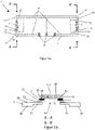
- FIGS. 1a-1c show a first embodiment with regard to a sensor unit 1 according to the invention.
- This sensor unit 1 has a carrier 2 .
- the carrier is as shown in the top view of the Fig. 1a can be seen, symmetrical.
- the symmetrical design relates in particular to the ends 3 and 4 of the beam 2.
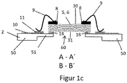
- FIG. 1b and 1c show sectional views according to section AA 'and BB' in alternative embodiments.
- a first resistance temperature sensor 5 and a second resistance temperature sensor 6 can also be seen.
- the resistance temperature sensors 5 and 6 are connected to the carrier 2 both structurally and electrically.
- the carrier 2 has two fastening lugs 51 in the area of the ends 3 and 4 in each case.
- the Fastening tabs 51 are, as in the sectional views of Fig. 1b and 1c can be seen, formed pointing to each other. There is no further carrier material between the two fastening tabs 51 .
- fastening tabs 51 have a smaller thickness and a smaller cross-section in comparison to the adjoining carrier sections 50 .
- recesses 55 can be seen. These recesses 55 are formed in such a way that the resistance temperature sensors 5 and 6 are connected to the fastening lugs 51 only on the undersides 31 at two sections 40 in each case.
- the resistance temperature sensors 5 and 6 on the top 30 can flow completely around all four end faces 32 .
- the undersides 31 can also largely be flowed around by a gas. Only the two attachment sections or sections 40 of the undersides 31 cannot be flowed around by gas.
- the sensors 5 and 6 are fixed to the carrier 2 at the fastening straps 51 .
- the resistance temperature sensors 5 and 6 each have contact pads 7 on the sections 40 of the undersides 31 .
- the resistance temperature sensors 5 and 6 can in turn be connected to contact pads 11 of the fastening straps 51 via these contact pads. This can be done according to the configuration of the Fig. 1b
- a further connection layer 12 can be formed between the contact pads 7 and 11 .
- the connecting layer 12 can be formed by a metal-containing sintering paste or by a conductive adhesive.
- the resistance temperature sensors 5 and 6 are preferably designed as flip-chip sensors.
- the resistance temperature sensors 5, 6 are formed in an imaginary storage of the sensor unit 1 on a storage surface in a plane that is formed above the carrier. In other words, the resistance temperature sensors 5 and 6 are formed entirely above a carrier 2 . This is not to be understood strictly mathematically and relates in particular to the area of the recess 60.
- the resistance temperature sensors 5 and 6 have bond pads 8 for this purpose. These are formed on the tops 30 .
- An electrical connection to the contact pads 11 formed in the area of the fastening tabs 51 can be established via wires 9 .
- a small adhesive layer 18 can be formed, for example, for structurally fixing the resistance temperature sensors 5 and 6 to the sensor 2 or to the fastening straps 51 .
- Electrical conductor tracks 10 can be seen on the upper side of the carrier 2 shown.
- the resistance temperature sensors 5 and 6 are electrically connected to these electrical conductor tracks. This is done by means of the contact pads 11.
- Contact areas 13 are located at the end of the conductor tracks 10. Leads to a monitoring and/or control unit can be attached to these contact areas 13.
- the battery pack 20 includes a Battery case 21.
- the battery case 21 has a case opening 22.
- a plurality of lithium-ion cells or battery cells 24 are formed in the battery housing 21 . These battery cells 24 are in turn located in a casing 23 .
- a sensor unit 1 is formed inside the housing 25 .
- This sensor unit 1 has two resistance temperature sensors 5 and 6 .
- the first resistance temperature sensor 5 is positioned in front of the housing opening 22, so that the resistance temperature sensor 5 in any gas flow 25 flowing from the housing interior 25 in the direction of the housing opening 22 (see Figure 2b ) is located.
- the second resistance temperature sensor 6, is designed at a distance from the housing opening 22, so that any gas stream 29 does not flow directly around it.
- the second resistance temperature sensor 6 is part of the common sensor unit 1.
- the two resistance temperature sensors 5 and 6 it would be possible for the two resistance temperature sensors 5 and 6 to be formed on sensor units that are separate from one another.
- the battery housing 21 includes, for example, a free volume inside the housing 25 of 0.05 m 3 .
- the free volume includes the areas within the battery housing 20 that are not occupied by condensed matter such as batteries, coolant, housing components, electronics or sensors. In the free volume there is gas under atmospheric pressure.
- the housing opening 22 connects the free volume with the exterior space 70 which is under atmospheric pressure.
- the housing opening 22 has an area of approximately 4 cm 2 .
- the sensor unit 1 is aligned in the housing interior 25 of the battery housing 21 in such a way that the sensitive surface of the resistance temperature sensor 5 opposes the gas flow 29 with its maximum surface.
- the temperature in the battery housing 21 is approximately 23°C.
- the resistance temperature sensors 5 and 6 are connected in series in the example shown and are both supplied with a constant current of, for example, 1-5 mA. This constant current heats the two resistance temperature sensors 5 and 6 to over 25° C., for example. This temperature is present at the resistance temperature sensors 5 and 6 when they are not located in a directed and therefore cooling gas flow 29 .
- gases within the battery housing 21 are released.
- the gases released generate an increase in pressure within the battery housing 21.
- the pressure building up in the battery housing 21 can increase by up to 10,000 pascals (100 mbar) within a few seconds. This increase in pressure corresponds to a volume increase of 5,000 cm 3 below normal pressure and temperature in the battery case 21 .
- the overpressure or the newly created volume of gas escapes via the housing opening 22 into the exterior space 70 within about 10 seconds.
- the volume flow density from the battery housing is 21,500 cm 3 /s. Consequently, the gas flow velocity in the area of the housing opening 22 is 1.25 m/s on average.
- This gas flow leads to a clearly detectable cooling of the resistance temperature sensor 5. Since the second resistance temperature sensor 6 is not or not directly in the gas flow 29, such a cooling of this resistance temperature sensor 6 cannot be detected.
- the electrical resistance of the resistance temperature sensor 5, which is operated at 3 mA, is 1,328.0 ohms (85° C.) in uncooled air. As the pressure in the battery case 21 increases, the resistance drops to 1320.4 ohms. This is due to the cooling gas flow 29 . The change in resistance corresponds to a decrease in temperature of the resistance temperature sensor 5 of 2 Kelvin.
- the electrical resistance of the resistance temperature sensor 6, which is not in the gas stream 29, is unchanged at 1,328.0 ohms during the thermal runaway.
- the resistance values of the two resistance temperature sensors 5 and 6 can be read out continuously by a control unit which is arranged outside the battery block 20, in particular outside the superordinate battery unit. If the control unit registers a change in resistance of the resistance temperature sensor 5 of >1 ohm within 3 seconds and the resistance of the resistance temperature sensor 6 remains almost unchanged, an alarm is activated, for example. This shows that pressure changes of 500 - 10,000 pascals in a battery case 21 can be demonstrated very precisely and that measures to warn or switch off the battery pack 20 can be initiated with this measurement signal.
- a further example is based on the fact that a pressure increase in the battery housing 21 caused by previous damage to a battery cell 24, in particular a lithium-ion battery cell, is only 2000 pascals. This pressure increase corresponds to a volume increase of 1,000 cm 3 under atmospheric pressure in the battery case 21 . The excess pressure or the newly created volume of gas escapes via the housing opening 22 into the exterior 70 within 10 seconds.
- the volume flow density from the battery housing 21 is 100 cm 3 /s. Consequently, the gas flow velocity in the area of the housing opening 22 is 0.25 m/s on average. This gas flow leads to a reliably demonstrable cooling of the resistance temperature sensor 5.
- the electrical resistance of the resistance temperature sensor 5, which is operated at 3 mA, is 1,328 ohms (85° C.) in uncooled air. As the pressure in the battery case 21 increases, the resistance drops to 1324.6 ohms. This is due to the cooling gas flow 29 . The change in resistance corresponds to a decrease in temperature of the resistance temperature sensor 5 by 0.9 Kelvin.
- the electrical resistance of the resistance temperature sensor 6 is unchanged at 1,328.0 ohms during the thermal runaway. It is thus shown that even small increases in pressure of 2,000 pascals in the battery housing 21, such as those that occur in the preliminary phase of thermal runaway, can be detected.
- the basic procedure corresponds to application examples 1 and 2, with the difference that the temperature in the battery housing 21 is approximately 70°C.
- the two resistance temperature sensors 5 and 6 are both subjected to a constant current of, for example, 20 mA. This constant current heats them both up Resistance temperature sensors 5 and 6 to 161.1 ° C each, provided they are not located in a directed and thus cooling gas flow 29.
- the resistance of the two resistance temperature sensors 5 and 6 is 1,614.6 ohms.
- a temperature reduction of 2 Kelvin of the resistance temperature sensor 5 in the gas stream 29 leads to a change in resistance to 1,607.2 ohms.
- This application example shows that precise temperature differences between two resistance temperature sensors 5 and 6 can be detected even at temperatures of 70° C. using a sensor unit 1 according to the invention.
- FIGS Figures 3a and 3b A further embodiment with regard to a sensor unit 1 according to the invention is shown in FIGS Figures 3a and 3b shown.
- the Figure 3a shows a plan view of the sensor unit according to the invention 1.
- a section AA' is shown in Figure 3b.
- only one resistance temperature sensor 5 is formed on the carrier 2 .
- This resistance temperature sensor 5 is positioned on fastening tabs 51 and fastened there to the carrier.
- the connection of the resistance temperature sensor 5 is as already in connection with Fig. 1b was presented and explained.
- the carrier 2 of Figure 3a again has a recess 55 so that a connection to a free space 60 can also be produced.
- the resistance temperature sensor 5 is designed as a flip chip sensor.
- Two electrical conductor tracks 10 are formed on the upper side of the carrier 2, to which the resistance temperature sensor 5 is electrically connected.
- the electrical conductor tracks 10 have contact areas 13 at the ends, which are used for contacting the resistance temperature sensor 5 and other connection wires.
- a sensor unit 1 such as those in the Figures 3a and 3b is shown.
- the control signals from the various resistance temperature sensors can be correlated with one another and examined with regard to stored threshold values.
- the amplification of the difference between the threshold value and the current value of the resistance temperature sensor also enables the resolution to be increased here.
- a detected difference signal allows a so-called zero-point detection for all exemplary embodiments. As soon as this difference is zero, the threshold value has already been reached. Sign changes can be detected particularly easily.
Landscapes
- Engineering & Computer Science (AREA)
- Power Engineering (AREA)
- Sustainable Energy (AREA)
- General Chemical & Material Sciences (AREA)
- Mechanical Engineering (AREA)
- Transportation (AREA)
- Chemical & Material Sciences (AREA)
- Chemical Kinetics & Catalysis (AREA)
- Electrochemistry (AREA)
- Sustainable Development (AREA)
- Life Sciences & Earth Sciences (AREA)
- Fluid Mechanics (AREA)
- Physics & Mathematics (AREA)
- Manufacturing & Machinery (AREA)
- General Physics & Mathematics (AREA)
- Secondary Cells (AREA)
Abstract
Die Erfindung betrifft eine Sensoreinheit 1 zur Detektion von Gasströmen 29 in einem Batterieblock 20 oder in einer Batterieeinheit, wobei die Sensoreinheit 1 einen Träger 2 und mindestens einen Widerstandstemperaturfühler 5, 6 aufweist, wobei der mindestens eine Widerstandstemperaturfühler 5, 6 mindestens sechs Seiten, nämlich eine Oberseite 30, eine Unterseite 31 und vier Stirnseiten 32, aufweist. Der Widerstandstemperaturfühler 5, 6 ist erfindungsgemäß derart mit dem Träger 2 verbunden, dass die Oberseite 30, die Unterseite 31 und mindestens zwei Stirnseiten 32 zumindest abschnittsweise von einem Gas umströmbar sind.The invention relates to a sensor unit 1 for detecting gas flows 29 in a battery block 20 or in a battery unit, the sensor unit 1 having a carrier 2 and at least one resistance temperature sensor 5, 6, the at least one resistance temperature sensor 5, 6 having at least six sides, namely one Top 30, a bottom 31 and four end faces 32 has. According to the invention, the resistance temperature sensor 5, 6 is connected to the carrier 2 in such a way that a gas can flow around the upper side 30, the lower side 31 and at least two end faces 32 at least in sections.
Description
Die Erfindung betrifft eine Sensoreinheit zur Detektion von Gasströmen in einem Batterieblock oder in einer Batterieeinheit. Des Weiteren betrifft die Erfindung einen Batterieblock mit mehreren in einem Gehäuse befindlichen Batteriezellen. Ferner betrifft die Erfindung eine Batterieeinheit mit mehreren in einem Batterieeinheitsgehäuse befindlichen Batterieblöcken. Außerdem betrifft die Erfindung ein Verfahren zur Detektion von Gasströmen in einem Batterieblock oder in einer Batterieeinheit.The invention relates to a sensor unit for detecting gas flows in a battery block or in a battery unit. Furthermore, the invention relates to a battery pack with a plurality of battery cells located in a housing. Furthermore, the invention relates to a battery unit with a plurality of battery blocks located in a battery unit housing. The invention also relates to a method for detecting gas flows in a battery block or in a battery unit.
Der Bedarf nach wiederaufladbaren Batterien mit hoher Energie- und Leistungsdichte ist seit der breiten Kommerzialisierung elektrisch angetriebener Fahrzeuge sprunghaft angestiegen. Derzeit gelten Lithium-Ionen-Batterien als Speicher mit der höchsten Energiedichte bezüglich verfügbarer Akkumulatoren. Daher werden Lithium-Ionen-Batterien seit geraumer Zeit bevorzugt in mobilen Endgeräten, die keine permanente Verbindung zu einem elektrischen Verbundnetz haben, eingesetzt. Der Wunsch nach immer größer werdenden Batterien mit hoher Leistung steigt. Um dies zu erreichen, werden einzelne Lithium-Ionen-Zellen zu Batterieblöcken in Serie und in Reihe geschaltet. Es ist jedoch bekannt, dass während des Betriebs von derartigen Batterieblöcken innerhalb einzelner Zellen Kurzschlüsse auftreten können, die wiederum Kettenreaktionen auslösen können. Derartige sicherheitsrelevante Störungen, die als "thermal runaway" bezeichnet werden, müssen somit frühzeitig erkannt werden, um geeignete Gegenmaßnahmen, wie ein sofortiges Abschalten des betreffenden Batterieblocks einleiten zu können.The demand for rechargeable batteries with high energy and power density has increased dramatically since the widespread commercialization of electrically powered vehicles. Lithium-ion batteries are currently considered to be storage devices with the highest energy density in relation to available accumulators. For this reason, lithium-ion batteries have been used for some time in mobile devices that are not permanently connected to an electrical network. The desire for ever larger batteries with high performance is increasing. To achieve this, individual lithium-ion cells are connected in series and in series to form battery blocks. However, it is known that short circuits can occur within individual cells during the operation of such battery blocks, which in turn can trigger chain reactions. Such safety-relevant faults, which are referred to as "thermal runaway", must therefore be recognized early on in order to be able to initiate suitable countermeasures, such as immediately switching off the battery block in question.
Aus dem Stand der Technik sind eine Vielzahl von Verfahren bekannt, die ein frühzeitiges Erkennen, des "thermal runaway" ermöglichen.A large number of methods are known from the prior art which enable early detection of "thermal runaway".
Unter anderem existieren Konzepte, die die Gasentwicklung innerhalb eines Batterieblocks oder der gesamten Batterieeinheit als Indikator für eine Störung in einer Zelle nutzen. Bei einem "thermal runaway" treten in einer Zelle unkontrollierte elektrochemische Prozesse auf, die zu einer plötzlichen Gasentwicklung führen. Derartig freiwerdende Gase können beispielsweise durch die auftretenden Gasvolumenflüsse innerhalb des Batterieblocks nachgewiesen werden. Des Weiteren ist es möglich, einen chemischen Nachweis bestimmter Gase mittels geeigneter Gasdetektoren zu führen.Among other things, there are concepts that use the gas development within a battery block or the entire battery unit as an indicator of a fault in a cell. In the event of a "thermal runaway", uncontrolled electrochemical processes occur in a cell, which lead to the sudden evolution of gas. Gases that are released in this way can, for example be detected by the gas volume flows occurring within the battery block. Furthermore, it is possible to carry out a chemical detection of certain gases using suitable gas detectors.
In
In
Ausgehend von dem Vorgenannten ist es Aufgabe der vorliegenden Erfindung, eine weiterentwickelte Sensoreinheit anzugeben, mit deren Hilfe es ermöglicht wird, frühzeitige Störungen innerhalb einer Batterie zu erkennen. Insbesondere sollen sogenannte "thermal runaways" bereits in der Entstehungsphase mittels einer weiterentwickelten Sensoreinheit detektierbar sein.Proceeding from the aforesaid, it is the object of the present invention to specify a further developed sensor unit with the aid of which it is possible to detect early faults within a battery. In particular, so-called "thermal runaways" should already be detectable in the development phase using a further developed sensor unit.
Des Weiteren ist es Aufgabe der vorliegenden Erfindung, einen weiterentwickelten Batterieblock anzugeben, der hinsichtlich einer im Batterieblock befindlichen Sensoreinheit weiterentwickelt ist.Furthermore, it is the object of the present invention to specify a further developed battery pack which is further developed with regard to a sensor unit located in the battery pack.
Des Weiteren ist es Aufgabe der vorliegenden Erfindung, eine weiterentwickelte Batterieeinheit anzugeben, die insbesondere hinsichtlich einer Sensoreinheit zur Detektion von Gasströmen weiterentwickelt ist. Ferner besteht eine Aufgabe der vorliegenden Erfindung darin, ein weiterentwickeltes Verfahren zur Detektion von Gasströmen in einem Batterieblock und/oder in einer Batterieeinheit anzugeben. Mit Hilfe eines weiterentwickelten Verfahrens soll insbesondere ein schnelleres Erkennen des "thermal runaways" ermöglicht werden als dies mit bislang bekannten Verfahren möglich ist.Furthermore, it is the object of the present invention to specify a further developed battery unit which is further developed in particular with regard to a sensor unit for detecting gas flows. A further object of the present invention is to specify a further developed method for detecting gas flows in a battery block and/or in a battery unit. With the help of a further developed method, a more rapid detection of the "thermal runaway" should be made possible in particular than is possible with previously known methods.
Erfindungsgemäß wird diese Aufgabe im Hinblick auf eine Sensoreinheit durch den Gegenstand des Anspruches 1, im Hinblick auf einen Batterieblock durch den Gegenstand des Patentanspruches 7, im Hinblick auf eine Batterieeinheit durch den Gegenstand des Patentanspruches 10, und im Hinblick auf ein Verfahren zur Detektion von Gasströmen in einem Batterieblock oder in einer Batterieeinheit durch den Gegenstand des Anspruches 13 gelöst.According to the invention, this object is achieved with regard to a sensor unit by the subject matter of
Die Erfindung beruht auf dem Gedanken, eine Sensoreinheit zur Detektion von Gasströmen in einem Batterieblock, oder in einer Batterieeinheit anzugeben, wobei die Sensoreinheit einen Träger und mindestens einen Widerstandstemperaturfühler aufweist. Der mindestens eine Widerstandstemperaturfühler weist mindestens sechs Seiten, nämlich eine Oberseite, eine Unterseite und vier Stirnseiten, auf, wobei der Widerstandstemperaturfühler derart mit dem Träger verbunden ist, dass die Oberseite, die Unterseite und mindestens zwei Stirnseiten zumindest abschnittsweise von einem Gas umströmbar sind.The invention is based on the idea of specifying a sensor unit for detecting gas flows in a battery block or in a battery unit, the sensor unit having a carrier and at least one resistance temperature sensor. The at least one resistance temperature sensor has at least six sides, namely an upper side, a lower side and four end faces, with the resistance temperature sensor being connected to the carrier in such a way that the upper side, the lower side and at least two end sides can be flowed around by a gas at least in sections.
Die Erfindung beruht somit auf dem Gedanken, einen Widerstandstemperaturfühler mit einem Träger derart zu verbinden, dass der Widerstandstemperaturfühler hinsichtlich der Oberseite, der Unterseite und mindestens zwei Stirnseiten zumindest abschnittsweise von einem Gas umströmbar ist. Mit einer derartigen Sensoreinheit ist es möglich, sehr schnell und äußerst genau, kleinste Bewegungen des Gasvolumens und somit kleinste Änderungen des Gasdrucks zu detektieren.The invention is thus based on the idea of connecting a resistance temperature sensor to a carrier in such a way that a gas can flow around the resistance temperature sensor at least in sections with regard to the upper side, the lower side and at least two end faces. With such a sensor unit, it is possible to detect very quickly and extremely precisely the smallest movements in the gas volume and thus the smallest changes in the gas pressure.
Als Oberseite und Unterseite eines Widerstandstemperaturfühlers sind die Seiten zu verstehen, die bei Auflage einer Sensoreinheit auf einer (gedachten) horizontalen Ablagefläche nach oben (Oberseite) bzw. nach unten (Unterseite) weisen. Die Ablage erfolgt dabei derart, dass der Träger der Sensoreinheit auf der (gedachten) horizontalen Ablagefläche aufliegt.The top and bottom of a resistance temperature sensor are the sides that point upwards (top) or downwards (bottom) when a sensor unit is placed on an (imaginary) horizontal storage surface. The storage takes place in such a way that the carrier of the sensor unit rests on the (imaginary) horizontal storage surface.
Bei den vier Stirnseiten handelt es sich um die vier zusätzlichen Seiten eines im Wesentlichen quaderförmigen Elements. Die vier Stirnseiten bilden mit anderen Worten die vier weiteren Umfangsseiten eines quaderförmigen Elements. Die vier Stirnseiten sind im Wesentlichen senkrecht zu der Oberseite sowie zur Unterseite ausgebildet. Herstellungsbedingt kann es hier hinsichtlich einer senkrechten Anordnung zu entsprechenden Varianten kommen.The four end faces are the four additional sides of an essentially cuboid element. In other words, the four end faces form the four further peripheral sides of a cuboid element. The four end faces are formed essentially perpendicularly to the top and to the bottom. Depending on the manufacturing process, there may be corresponding variants with regard to a vertical arrangement.
Aufgrund der vorgesehenen Verbindung des Widerstandstemperaturfühlers mit dem Träger derart, dass die Oberseite, die Unterseite und mindestens zwei Stirnseiten zumindest abschnittsweise von einem Gas umströmbar sind, kann bereits ein vergleichsweise geringer Gasstrom detektiert werden.Due to the intended connection of the resistance temperature sensor to the carrier in such a way that a gas can flow around the upper side, the lower side and at least two end faces at least in sections, a comparatively small gas flow can already be detected.
Vorzugsweise ist der mindestens eine Widerstandstemperaturfühler an höchstens zwei Abschnitten einer Seite, vorzugsweise an der Unterseite, mittel- oder unmittelbar mit dem Träger verbunden. Die beschriebene Verbindung des Widerstandstemperaturfühlers mit dem Träger betrifft hierbei vorrangig die bauliche Verbindung mit dem Träger. Mit anderen Worten betrifft die Verbindung die Anordnung des Widerstandstemperaturfühlers in Relation zum Träger sowie zur Befestigung. Die Verbindung betrifft vorrangig nicht die elektrische Verbindung des Widerstandstemperaturfühlers mit dem Träger. Allerdings kann die beschriebene bauliche Verbindung zusätzlich auch eine elektrische Verbindung betreffen bzw. eine derart kombinierte Verbindung (baulich und elektrisch) ermöglichen.The at least one resistance temperature sensor is preferably connected directly or indirectly to the carrier on at most two sections of one side, preferably on the underside. The described connection of the resistance temperature sensor to the carrier relates primarily to the structural connection to the carrier. In other words, the connection relates to the placement of the resistance temperature sensor in relation to the carrier and the mounting. The connection does not primarily concern the electrical connection of the RTD to the carrier. However, the structural connection described can also relate to an electrical connection or enable such a combined connection (structural and electrical).
Sofern der Widerstandstemperaturfühler an höchstens zwei Abschnitten einer Seite, vorzugsweise an der Unterseite, mit dem Träger verbunden ist, ist es möglich, dass die Oberseite, sowie die vier Stirnseiten vollständig von einem Gas umströmbar sind. Die Unterseite ist aufgrund der Verbindung des Widerstandstemperaturfühlers mit dem Träger zumindest abschnittsweise, vorzugsweise überwiegend, von einem Gas umströmbar. Bei einer derartigen Befestigungskonfiguration ist somit der Widerstandstemperaturfühler mit Ausnahme der zwei Abschnitte zur Verbindung des Widerstandstemperaturfühlers vollständig von einem Gas umströmbar.If the resistance temperature sensor is connected to the carrier on at most two sections of one side, preferably on the underside, it is possible for a gas to flow completely around the upper side and the four end faces. Due to the connection of the resistance temperature sensor to the carrier, a gas can flow around the underside at least in sections, preferably predominantly. With such a fastening configuration, a gas can flow completely around the resistance temperature sensor, with the exception of the two sections for connecting the resistance temperature sensor.
In einer Ausführungsform der Erfindung ist es möglich, dass der Widerstandstemperaturfühler mit dem Träger mittels Adhäsion verbunden ist. Beispielsweise kann der Widerstandstemperaturfühler mit dem Träger verklebt sein.In an embodiment of the invention it is possible that the resistance temperature sensor is connected to the carrier by means of adhesion. For example, the resistance temperature sensor can be glued to the carrier.
In einer weiteren Ausführungsform der Erfindung ist es möglich, dass der Widerstandstemperaturfühler mit dem Träger mittels eines Sintermaterials verbunden ist.In a further embodiment of the invention it is possible for the resistance temperature sensor to be connected to the carrier by means of a sintered material.
In wiederum einer weiteren Ausführungsform der Erfindung ist es möglich, dass die Verbindung des Widerstandstemperaturfühlers mit dem Träger gleichzeitig eine elektrische Kontaktierung darstellt. Hierbei ist es möglich, dass der Widerstandstemperaturfühler mindestens einen, vorzugsweise mindestens zwei Kontaktpads aufweist. Der Widerstandstemperaturfühler ist in einer derartigen Ausführungsform der Erfindung vorzugsweise als Flipchip-Sensor ausgestaltet. Hierbei weist ein Widerstandstemperaturfühler auf einer Seite, vorzugsweise auf der Unterseite, jeweils zwei Kontaktpads auf. Über diese Kontaktpads werden die Widerstandstemperaturfühler beispielsweise mit weiteren Kontaktpads des Trägers mechanisch und elektrisch verbunden. Die tatsächliche Verbindung erfolgt vorzugsweise über eine metallhaltige Sinterpaste oder einen Leitkleber.In yet another embodiment of the invention, it is possible for the connection of the resistance temperature sensor to the carrier to constitute an electrical contact at the same time. It is possible here for the resistance temperature sensor to have at least one, preferably at least two, contact pads. In such an embodiment of the invention, the resistance temperature sensor is preferably designed as a flip-chip sensor. In this case, a resistance temperature sensor has two contact pads on one side, preferably on the underside. The resistance temperature sensors are mechanically and electrically connected, for example, to further contact pads of the carrier via these contact pads. The actual connection is preferably made using a metal-containing sinter paste or a conductive adhesive.
Es ist möglich, dass der Träger mindestens zwei Befestigungslaschen aufweist, wobei die mindestens zwei Befestigungslaschen zueinanderweisend ausgebildet sind und der mindestens eine Widerstandstemperaturfühler an den Befestigungslaschen mittel- oder unmittelbar mit dem Träger mechanisch verbunden ist. Vorzugsweise ist der Widerstandstemperaturfühler bei einer derartigen Ausführungsform der Erfindung an den höchstens zwei Abschnitten einer Seite, vorzugsweise der Unterseite, mit den zwei genannten Befestigungslaschen verbunden.It is possible for the carrier to have at least two fastening straps, with the at least two fastening straps being designed to face one another and the at least one resistance temperature sensor being directly or indirectly mechanically connected to the fastening straps. In such an embodiment of the invention, the resistance temperature sensor is preferably connected to the two fastening lugs mentioned on at most two sections of one side, preferably the underside.
Als Befestigungslaschen eines Trägers sind vorzugsweise von weiteren Trägerabschnitten (seitliche) abstehende Laschen zu verstehen. Zwischen mindestens zwei Befestigungslaschen ist vorzugsweise kein weiteres Trägermaterial ausgebildet. Mit anderen Worten sind die mindestens zwei Befestigungslaschen beabstandet zueinander ausgebildet, wobei der Abstand zwischen den mindestens zwei Befestigungslaschen bzw. der jeweils zueinandergeordneten Befestigungslaschen als Freiraum oder als Materialaussparung ausgebildet ist.Fastening lugs of a carrier are preferably to be understood as lugs protruding (laterally) from further carrier sections. Preferably no further carrier material is formed between at least two fastening straps. In other words, the at least two fastening straps are spaced apart from one another, with the distance between the at least two fastening straps or the respective mutually arranged fastening straps being designed as a free space or as a material recess.
Vorzugsweise weist mindestens eine Befestigungslasche eine im Vergleich zu angrenzenden Trägerabschnitten zumindest abschnittsweise eine geringere Dicke und/oder einen geringeren Querschnitt auf. Bevorzugt weisen die mindestens zwei Befestigungslaschen jeweils eine im Vergleich zu angrenzenden Trägerabschnitten zumindest abschnittsweise geringere Dicke und/oder einen geringeren Querschnitt auf. Im Bereich der verringerten Dicke bzw. des verringerten Querschnittes wird somit zusätzlicher Raum zur Verfügung gestellt, der hinsichtlich einer verbesserten Gasströmung vorteilhaft ist. Die Umströmung des Gases um den Widerstandstemperaturfühler kann je nach am Sensorort auftretender Gasgeschwindigkeit turbulent oder laminar sein.Preferably, at least one fastening tab has a smaller thickness and/or a smaller cross-section, at least in sections, in comparison to adjacent carrier sections. Preferably, the at least two fastening straps each have an im Compared to adjoining carrier sections at least partially smaller thickness and / or a smaller cross-section. Additional space is thus made available in the region of the reduced thickness or the reduced cross section, which is advantageous with regard to an improved gas flow. The flow of gas around the resistance temperature sensor can be turbulent or laminar, depending on the gas velocity occurring at the sensor location.
Der über wesentliche Abschnitte frei umströmbare Widerstandstemperaturfühler mit typischen Ausdehnungen im Millimeterbereich stellt in dieser Geometrie ein strömungsdynamisch kleines Hindernis dar, welches turbulente Gasstromanteile induzieren kann und den Wärmeübertrag an die Gasphase noch mehr begünstigen kann.In this geometry, the resistance temperature sensor, which can be freely flowed around over significant sections and typically extends in the millimeter range, represents a small obstacle in terms of flow dynamics, which can induce turbulent gas flow components and can promote heat transfer to the gas phase even more.
Der mindestens eine Widerstandstemperaturfühler ist erfindungsgemäß derart mit dem Träger verbunden, dass der Widerstandstemperaturfühler in einem guten thermischen Kontakt mit dem umgebenden Gas steht und gleichzeitig die Wärmeableitung vom Widerstandstemperaturfühler zum Träger minimal ist. Die beschriebenen Befestigungslaschen verbessern diesen Punkt erheblich.The at least one resistance temperature sensor is connected to the carrier according to the invention in such a way that the resistance temperature sensor is in good thermal contact with the surrounding gas and at the same time the heat dissipation from the resistance temperature sensor to the carrier is minimal. The fastening tabs described improve this point considerably.
In einer besonders bevorzugten Ausführungsform der Erfindung weist die Sensoreinheit mindestens zwei Widerstandstemperaturfühler auf.In a particularly preferred embodiment of the invention, the sensor unit has at least two resistance temperature sensors.
Es ist möglich, dass der Träger zwei Längsenden aufweist, wobei an jedem Längsende ein Widerstandstemperaturfühler ausgebildet ist. Mit anderen Worten sind zwei Widerstandstemperaturfühler an zwei Längsenden des Trägers der Sensoreinheit angeordnet.It is possible for the carrier to have two longitudinal ends, with a resistance temperature sensor being formed at each longitudinal end. In other words, two resistance temperature sensors are arranged at two longitudinal ends of the support of the sensor unit.
Sofern eine Sensoreinheit mindestens zwei Widerstandstemperaturfühler aufweist, sind die Widerstandstemperaturfühler vorzugsweise gleichartig ausgebildet.If a sensor unit has at least two resistance temperature sensors, the resistance temperature sensors are preferably of the same design.
Als Widerstandstemperaturfühler eignen sich insbesondere massearme Temperatursensoren. Besonders bevorzugt handelt es sich bei dem mindestens einen Widerstandstemperaturfühler um einen platinbasierten Temperatursensor, wie beispielsweise einen Pt1000 oder Pt10000-Sensor.Low-mass temperature sensors are particularly suitable as resistance temperature sensors. The at least one resistance temperature sensor is particularly preferably a platinum-based temperature sensor, such as a Pt1000 or Pt10000 sensor.
Derartige Sensoren weisen sowohl einen hohen Temperaturkoeffizienten als auch einen hohen Grundwiderstand auf. Der Grundwiderstand R0 beträgt beispielsweise 1000 Ohm oder gar 10000 Ohm bei 0 °C. Daher sind derartige Sensoren aufgrund hoher Temperaturkoeffizienten und aufgrund eines hohen Grundwiderstandes sehr sensitiv. Aufgrund dessen können kleine Temperaturänderungen äußerst genau detektiert werden.Such sensors have both a high temperature coefficient and a high basic resistance. The basic resistance R 0 is, for example, 1000 ohms or even 10000 ohms at 0°C. Therefore, such sensors are very sensitive due to high temperature coefficients and due to a high basic resistance. Because of this, small temperature changes can be detected extremely accurately.
Des Weiteren verfügen derartige massearme Temperatursensoren aufgrund der geringen Masse über eine schnelle Ansprechzeit und über eine hohe Eigenerwärmung. Die Eigenerwärmung kann dabei größer 180 K/W sein.Furthermore, due to the low mass, such low-mass temperature sensors have a fast response time and high self-heating. The self-heating can be greater than 180 K/W.
Massearme Temperatursensoren eignen sich besonders zur Verwendung bei einer erfindungsgemäßen Sensoreinheit, da über den gesamten relevanten Temperaturbereich sowohl die Sensitivität als auch die Genauigkeit konstant ist.Low-mass temperature sensors are particularly suitable for use in a sensor unit according to the invention, since both the sensitivity and the accuracy are constant over the entire relevant temperature range.
Vorzugsweise befindet sich unterhalb der Unterseite des mindestens einen Widerstandstemperaturfühlers überwiegend kein Abschnitt des Trägers. Mit anderen Worten sind unterhalb der Unterseite des mindestens einen Widerstandstemperaturfühlers überwiegend keine Abschnitte des Trägers ausgebildet.There is preferably no section of the carrier below the underside of the at least one resistance temperature sensor. In other words, predominantly no sections of the carrier are formed below the underside of the at least one resistance temperature sensor.
Vorzugsweise sind unterhalb der Unterseite des mindestens einen Widerstandstemperaturfühlers lediglich derartige Abschnitte des Trägers ausgebildet, die zur Verbindung des Widerstandstemperaturfühlers mit dem Träger dienen.Preferably, only those sections of the carrier that are used to connect the resistance temperature sensor to the carrier are formed below the underside of the at least one resistance temperature sensor.
Bevorzugt ist unterhalb der Unterseite des mindestens einen Widerstandstemperaturfühlers ein Freiraum ausgebildet. Dieser Freiraum ist insbesondere bei einer Ablage der Sensoreinheit auf einer (gedachten) Ablagefläche derart, dass der Träger auf der Ablagefläche aufliegt, sichtbar. In vertikaler Erstreckung sind vorzugsweise zwischen der Unterseite des Widerstandstemperaturfühlers und der (gedachten) Auflagefläche überwiegend keine Abschnitte des Trägers ausgebildet. Überlappungsbereiche mit Abschnitten des Trägers sind vorzugsweise lediglich bezüglich der Verbindungsabschnitte des Widerstandstemperaturfühlers mit dem Träger ausgebildet.A free space is preferably formed below the underside of the at least one resistance temperature sensor. This free space is visible in particular when the sensor unit is placed on an (imaginary) storage area in such a way that the carrier rests on the storage area. In the vertical extension, preferably no sections of the carrier are formed between the underside of the resistance temperature sensor and the (imaginary) bearing surface. Areas of overlap with sections of the carrier are preferably formed only with respect to the connecting sections of the resistance temperature sensor with the carrier.
Der mindestens eine Widerstandstemperaturfühler ist derart auf dem Träger positioniert und mit dem Träger verbunden, dass der Widerstandstemperaturfühler in einem guten thermischen Kontakt mit dem umgebenden Gas steht und gleichzeitig die Wärmeableitung vom Widerstandstemperaturfühler zum Träger minimal ist.The at least one RTD is positioned on and bonded to the carrier such that the RTD is in good thermal contact with the surrounding gas while minimizing heat dissipation from the RTD to the carrier.
In einer bevorzugten Ausführungsform der Erfindung wird dies dadurch realisiert, indem der Träger mindestens eine Aussparung oder Einbuchtung aufweist, wobei der mindestens eine Widerstandstemperaturfühler diese Aussparung oder Einbuchtung überspannt.In a preferred embodiment of the invention, this is achieved in that the carrier has at least one cutout or indentation, with the at least one resistance temperature sensor spanning this cutout or indentation.
Vorzugsweise wird der Widerstandstemperaturfühler lediglich an zwei Abschnitten, die jeweils zwei seitliche Endabschnitte bilden, mit dem Träger verbunden. Dies bezieht sich auf eine bauliche Verbindung des Widerstandstemperaturfühlers mit dem Träger und nicht zwangsläufig eine elektrische Verbindung, wobei eine kombinierte elektrische Verbindung nicht ausgeschlossen ist.The resistance temperature sensor is preferably only connected to the carrier at two sections, each of which forms two lateral end sections. This relates to a structural connection of the resistance temperature sensor to the carrier and not necessarily an electrical connection, although a combined electrical connection is not excluded.
Eine derartige Verbindung des mindestens einen Widerstandstemperaturfühlers mit dem Träger weist mehrere Vorteile auf. Zum einen ist eine derartige Verbindung des Widerstandstemperaturfühlers mit dem Träger relativ steif und verhindert ein mechanisches Schwingen des Widerstandstemperaturfühlers relativ zum Träger. Des Weiteren kann aufgrund dieser Verbindung ein großer Anteil des Widerstandstemperaturfühlers von einem Gas umströmbar ausgebildet sein. Insbesondere können sowohl die Ober- als auch die Unterseite größtenteils in direktem thermischen Kontakt mit dem umgebenden Gas stehen.Such a connection of the at least one resistance temperature sensor to the carrier has several advantages. On the one hand, such a connection of the resistance temperature sensor to the carrier is relatively stiff and prevents the resistance temperature sensor from mechanically oscillating relative to the carrier. Furthermore, because of this connection, a large proportion of the resistance temperature sensor can be designed so that a gas can flow around it. In particular, both the top and the bottom can be in direct thermal contact with the surrounding gas for the most part.
Des Weiteren ist die Wärmeableitung über thermische Brücken über dem Widerstandstemperaturfühler und dem Träger minimal. Dies ist auf die geringe Kontaktfläche bzw. Verbindungsfläche zwischen dem Widerstandstemperaturfühler und dem Träger zurückzuführen.Furthermore, heat dissipation via thermal bridges across the RTD and the substrate is minimal. This is due to the small contact area between the RTD and the substrate.
Eine weitere Reduzierung der Wärmeleitung von dem mindestens einen Widerstandstemperaturfühler zum Träger wird dadurch realisiert, dass eine mögliche Befestigungslasche ebenfalls relativ massearm ausgebildet ist. Es ist möglich, dass die vorzugsweise mindestens eine Befestigungslasche gleichzeitig eine elektrische Kontaktierung mit dem mindestens einen Widerstandstemperaturfühler ermöglicht.A further reduction in the heat conduction from the at least one resistance temperature sensor to the carrier is realized in that a possible fastening strap is also designed with relatively little mass. It is possible for the preferably at least one fastening tab to enable electrical contact to be made with the at least one resistance temperature sensor at the same time.
Wie bereits erläutert, kann mindestens eine Befestigungslasche eine geringere Dicke als angrenzende Trägerabschnitte aufweisen. Des Weiteren ist es möglich, dass die mindestens eine Befestigungslasche eine im Vergleich zu einem angrenzenden Trägerabschnitt einen geringeren Querschnitt aufweist. Dies ermöglicht zusammenfassend das Ausbilden einer massearmen Befestigungslasche. Des Weiteren ist es möglich, dass mindestens eine Befestigungslasche auf der Oberfläche, d. h. auf der zum Widerstandstemperaturfühler weisenden Oberfläche mindestens eine Zuleitung oder mindestens ein Kontaktpad aufweist.As already explained, at least one fastening tab can have a smaller thickness than adjacent carrier sections. Furthermore, it is possible for the at least one fastening strap to have a smaller cross section in comparison to an adjoining carrier section. In summary, this enables the formation of a low-mass fastening strap. Furthermore, it is possible that at least one Fastening strap on the surface, ie on the surface facing the resistance temperature sensor, has at least one lead or at least one contact pad.
Des Weiteren ist es möglich, dass der Träger und/oder die Befestigungslaschen Perforationen aufweisen. Mit Perforationen sind z.B. Löcher im Träger und/oder Befestigungslachen gemeint, vorzugsweise in der Nähe der Verbindungsstellen mit dem Widerstandstemperaturfühler. Dies ermöglicht es, den relevanten Querschnitt des Trägers und/oder der Befestigungslaschen zu reduzieren und eine Wärmeableitung des Widerstandstemperaturfühlers über den Träger zu minimieren.Furthermore, it is possible for the carrier and/or the fastening tabs to have perforations. By perforations is meant, for example, holes in the carrier and/or mounting tabs, preferably near the junctions with the RTD. This makes it possible to reduce the relevant cross-section of the carrier and/or the fastening tabs and to minimize heat dissipation of the resistance temperature sensor via the carrier.
Bei dem mindestens einen Widerstandstemperaturfühler, der vorzugsweise massearm ausgebildet ist, kann es sich z. B. um ein SMD-Bauteil handeln. Des Weiteren ist es möglich, dass der mindestens eine Widerstandstemperaturfühler eine temperaturempfindliche Platin-Struktur aufweist, die auf ein Substrat abgeschieden wurde. Ein derartiges Substrat eines Widerstandstemperaturfühlers kann auf eine minimale Dicke reduziert werden.The at least one resistance temperature sensor, which is preferably designed with low mass, it can be z. B. be an SMD component. Furthermore, it is possible for the at least one resistance temperature sensor to have a temperature-sensitive platinum structure that has been deposited on a substrate. Such a RTD substrate can be reduced to a minimum thickness.
Die beschriebenen Ausführungsformen hinsichtlich eines Widerstandstemperaturfühlers (SMD-Bauteil oder temperaturempfindliche Platin-Struktur auf Substrat) ermöglichen es, einen dynamischen Widerstandstemperaturfühler zur Verfügung zu stellen. Ein derartiger Widerstandstemperaturfühler weist eine geringe Ansprechzeit und maximalen Signalhub auf.The described embodiments with regard to a resistance temperature sensor (SMD component or temperature-sensitive platinum structure on substrate) make it possible to provide a dynamic resistance temperature sensor. Such a resistance temperature sensor has a short response time and maximum signal swing.
Vorzugsweise weist der mindestens eine Widerstandstemperaturfühler eine Masse von weniger als 20 mg, vorzugsweise weniger als 10 mg, besonders bevorzugt weniger als 5 mg, auf.The at least one resistance temperature sensor preferably has a mass of less than 20 mg, preferably less than 10 mg, particularly preferably less than 5 mg.
Es ist möglich, dass der Widerstandstemperaturfühler ein SMD-Bauteil ist. Derartige SMD-Bauteile weisen eine besonders kleine Bauteilgröße auf.It is possible that the RTD is an SMD component. Such SMD components have a particularly small component size.
Es ist außerdem möglich, dass ein derartiges SMD-Bauteil als Flipchip ausgebildet ist. Mit anderen Worten kann der mindestens eine Widerstandstemperaturfühler ein SMD-Flipchip-Sensor sein. Ein derartiges Bauteil kann sowohl baulich als auch elektrisch mit dem Träger im gleichen Verbindungsschritt verbunden werden.It is also possible for such an SMD component to be in the form of a flip chip. In other words, the at least one resistance temperature sensor can be an SMD flip-chip sensor. Such a component can be connected both structurally and electrically to the carrier in the same connection step.
Alternativ ist es möglich, dass SMD-Flipchip-Sensoren an zwei Enden mittels einer Klebung mit dem Träger, insbesondere mit Befestigungslaschen des Trägers, baulich verbunden werden. Eine elektrische Verbindung kann über Drähte, die beispielsweise durch Bonding oder Löten mit Kontaktpads des Trägers, insbesondere mit Kontaktpads an den Befestigungslaschen, verbunden werden, hergestellt werden.Alternatively, it is possible for SMD flip-chip sensors to be structurally connected at two ends to the carrier, in particular to fastening lugs of the carrier, by means of an adhesive bond. An electrical connection can be made using wires, for example by bonding or soldering Contact pads of the carrier, in particular with contact pads on the fastening straps, are connected.
In wiederum einer weiteren Ausführungsform ist es möglich, dass der mindestens eine Widerstandstemperaturfühler mittels Anschlussdrähten sowohl baulich als auch elektrisch mit dem Träger verbunden ist. Eine derartige Befestigung und entsprechende Positionierung eines Widerstandstemperaturfühlers kann als freischwebende Positionierung des mindestens einen Widerstandstemperaturfühlers bezeichnet werden. Bei einer derartigen Ausführungsform der Erfindung ist es möglich, dass der mindestens eine Widerstandstemperaturfühler über den Träger hinausragt.In yet another embodiment, it is possible for the at least one resistance temperature sensor to be connected both structurally and electrically to the carrier by means of connecting wires. Such a fastening and corresponding positioning of a resistance temperature sensor can be referred to as free-floating positioning of the at least one resistance temperature sensor. In such an embodiment of the invention, it is possible for the at least one resistance temperature sensor to protrude beyond the carrier.
Insbesondere bei der Ausbildung von mindestens zwei Widerstandstemperaturfühlern ist es möglich, dass mindestens ein Widerstandstemperaturfühler besonders geschützt auf dem Träger angeordnet ist. Vorzugsweise handelt es sich bei dem geschützt angebrachten Widerstandstemperaturfühler um einen Referenzwiderstandstemperaturfühler. Eine geschützte Positionierung und Verbindung eines mindestens einen Widerstandstemperaturfühlers kann beispielsweise mittels einer Hülse oder Kappe oder anderen Passivierungsbauteilen oder Passivierungsoptionen erfolgen.In particular when at least two resistance temperature sensors are formed, it is possible for at least one resistance temperature sensor to be arranged on the carrier in a particularly protected manner. The protectively mounted resistance temperature sensor is preferably a reference resistance temperature sensor. A protected positioning and connection of at least one resistance temperature sensor can take place, for example, by means of a sleeve or cap or other passivation components or passivation options.
Der Träger der Sensoreinheit kann beispielsweise als Epoxy-Leiterplatte ausgebildet sein. Es ist möglich, dass der Träger aus standardmäßig bekannten Leiterplattenmaterialien gebildet ist.The carrier of the sensor unit can be designed as an epoxy printed circuit board, for example. It is possible for the carrier to be formed from printed circuit board materials that are known as standard.
In einer besonders bevorzugten Ausführungsform der Erfindung ist der Träger symmetrisch ausgebildet. Die symmetrische Ausbildung des Trägers, die insbesondere die diesbezügliche Positionierung von beispielsweise mindestens zwei Widerstandstemperaturfühlern betrifft, hat den Vorteil, dass eine Wärmeableitung ohne einen vorhandenen Gasstrom auf beiden Seiten gleich ist. Mit anderen Worten sind bei einer Ausführung von mindestens zwei Widerstandstemperaturfühlern bei einer symmetrischen Ausgestaltung des Trägers beide Widerstandstemperaturfühler den gleichen Einflüssen ausgesetzt.In a particularly preferred embodiment of the invention, the carrier is designed symmetrically. The symmetrical design of the carrier, which relates in particular to the relevant positioning of, for example, at least two resistance temperature sensors, has the advantage that heat dissipation is the same on both sides without an existing gas flow. In other words, in an embodiment of at least two resistance temperature sensors with a symmetrical design of the carrier, both resistance temperature sensors are exposed to the same influences.
Ein weiterer Aspekt der Erfindung betrifft einen Batterieblock mit mehreren in einem Gehäuse befindlichen Batteriezellen, insbesondere Lithium-Ionen-Batteriezellen, wobei das Gehäuse mindestens eine Gehäuseöffnung aufweist und in dem Gehäuse mindestens eine erste erfindungsgemäße Sensoreinheit befindlich ist.A further aspect of the invention relates to a battery block with a plurality of battery cells, in particular lithium-ion battery cells, located in a housing, the housing having at least one housing opening and at least one first sensor unit according to the invention being located in the housing.
Vorzugsweise ist die erste Sensoreinheit derart im Gehäuse positioniert, dass der mindestens eine Widerstandstemperaturfühler vor der Gehäuseöffnung derart positioniert ist derart, dass der Widerstandstemperaturfühler in einem etwaigen vom Gehäuseinneren in Richtung der Gehäuseöffnung strömenden Gasstrom befindlich ist. Vorzugsweist ist, sofern die Sensoreinheit mehrere Widerstandstemperaturfühler aufweist, lediglich einer der Widerstandstemperaturfühler vor der Gehäuseöffnung ausgebildet.The first sensor unit is preferably positioned in the housing such that the at least one resistance temperature sensor is positioned in front of the housing opening such that the resistance temperature sensor is located in any gas flow flowing from the interior of the housing in the direction of the housing opening. If the sensor unit has a plurality of resistance temperature sensors, preferably only one of the resistance temperature sensors is formed in front of the housing opening.
Ein etwaiger strömender Gasstrom tritt bei einem Ausgleich des Druckunterschiedes im Gehäuse auf. Die mindestens eine Gehäuseöffnung des Gehäuses dient dem Ausgleich von Druckunterschieden zwischen dem Gehäuseinneren und dem Gehäuseäußeren. Derartige Druckunterschiede treten unter Umständen bereits im Normalbetrieb auf, da sich Batterien beim Laden und Entladen erwärmen und ergänzend auch wegen ablaufender chemischer Prozesse dabei gleichzeitig ihr Volumen ändern.Any flowing gas flow occurs when the pressure difference in the housing equalizes. The at least one housing opening of the housing serves to equalize pressure differences between the housing interior and the housing exterior. Such pressure differences may already occur during normal operation, since batteries heat up during charging and discharging and, in addition, their volume also changes at the same time due to chemical processes taking place.
Die mindestens eine Sensoreinheit ist somit derart im Gehäuse des Batterieblocks positioniert, dass ein Widerstandstemperaturfühler in einem Gasstrom befindlich ist, der sich beim Ausgleich des Druckunterschieds im Gehäuse des Batterieblocks ausbildet. Ein am Widerstandstemperaturfühler vorbeiströmender Gasstrom führt zu einer Temperaturänderung des Widerstandstemperaturfühlers. Aufgrund einer Messung der Temperaturänderung am Widerstandstemperaturfühler kann daher auf eine Druckänderung im Gehäuse rückgeschlossen werden.The at least one sensor unit is thus positioned in the housing of the battery block in such a way that a resistance temperature sensor is located in a gas flow that forms when the pressure difference in the housing of the battery block is equalized. A flow of gas flowing past the resistance temperature sensor causes the temperature of the resistance temperature sensor to change. Based on a measurement of the temperature change at the resistance temperature sensor, conclusions can therefore be drawn about a pressure change in the housing.
In einer besonders bevorzugten Ausführungsform der Erfindung ist der an der Gehäuseöffnung ausgebildete Widerstandstemperaturfühler aufgrund Stromfluss gegenüber seiner Umgebung elektrisch vorgeheizt. Ein zu detektierender Gasstrom führt zu einer Abkühlung des Widerstandstemperaturfühlers, die detektiert werden kann.In a particularly preferred embodiment of the invention, the resistance temperature sensor formed on the housing opening is electrically preheated relative to its surroundings due to the flow of current. A gas flow to be detected leads to a cooling of the resistance temperature sensor, which can be detected.
In einer weiteren Ausführungsform der Erfindung sind im Gehäuse des Batterieblocks mindestens zwei Widerstandstemperaturfühler ausgebildet. Ein zweiter Widerstandstemperaturfühler ist von der Gehäuseöffnung beabstandet ausgebildet und wird von einem etwaigen Gasstrom nicht umströmt, wobei der zweite Widerstandstemperaturfühler auf der ersten Sensoreinheit oder einer mindestens zweiten Sensoreinheit angeordnet ist.In a further embodiment of the invention, at least two resistance temperature sensors are formed in the housing of the battery block. A second resistance temperature sensor is formed at a distance from the housing opening and is not surrounded by any gas flow, the second resistance temperature sensor being arranged on the first sensor unit or on at least a second sensor unit.
Demnach ist es möglich im Gehäuse des Batterieblocks lediglich eine Sensoreinheit auszubilden. Auf dieser Sensoreinheit sind ein erster Widerstandstemperaturfühler sowie ein zweiter Widerstandstemperaturfühler ausgebildet. Der erste Widerstandstemperaturfühler ist vor der Gehäuseöffnung positioniert. Der zweite Widerstandstemperaturfühler ist in diesem Fall von der Gehäuseöffnung beabstandet ausgebildet.Accordingly, it is possible to form only one sensor unit in the housing of the battery pack. On this sensor unit are a first resistance temperature sensor and a second resistance temperature sensor formed. The first resistance temperature sensor is positioned in front of the housing opening. In this case, the second resistance temperature sensor is formed at a distance from the housing opening.
Alternativ oder zusätzlich ist es möglich, dass bei Vorhandensein von mindestens zwei Widerstandstemperaturfühlern beide Widerstandstemperaturfühler unterschiedlichen Sensoreinheiten zugeordnet sind. Die Sensoreinheiten sind somit an unterschiedlichen Positionen im Gehäuse des Batterieblocks ausgebildet. Eine erste Sensoreinheit ist dabei derart positioniert, dass der erste Widerstandstemperaturfühler vor der Gehäuseöffnung positioniert ist. Eine zweite Sensoreinheit ist hingegen derart positioniert, dass der zweite Widerstandstemperaturfühler von der Gehäuseöffnung beabstandet ausgebildet ist. Ein etwaiger zweiter Widerstandstemperaturfühler ist im Gehäuse des Batterieblocks derart angeordnet bzw. positioniert, dass an dieser Stelle ein vergleichsweise geringerer Gasstrom zu erwarten ist.Alternatively or additionally, it is possible that when at least two resistance temperature sensors are present, both resistance temperature sensors are assigned to different sensor units. The sensor units are thus formed at different positions in the housing of the battery pack. A first sensor unit is positioned in such a way that the first resistance temperature sensor is positioned in front of the housing opening. A second sensor unit, on the other hand, is positioned in such a way that the second resistance temperature sensor is formed at a distance from the housing opening. A possible second resistance temperature sensor is arranged or positioned in the housing of the battery pack in such a way that a comparatively lower gas flow is to be expected at this point.
Ein zweiter Widerstandstemperaturfühler dient als Referenz-Widerstandstemperaturfühler. Vorzugweise sind bei Vorhandensein von mehreren Widerstandstemperaturfühlern alle Widerstandstemperaturfühler baugleich ausgebildet. Vorzugsweise werden die Widerstandstemperaturfühler mit dem gleichen konstanten Strom beaufschlagt, der die Widerstandstemperaturfühler erwärmt. Vorzugsweise wird der Strom derart gewählt, dass die sich einstellende Temperatur der Widerstandstemperaturfühler ausreichend oberhalb einer Umgebungstemperatur liegt.A second RTD serves as a reference RTD. If several resistance temperature sensors are present, all resistance temperature sensors are preferably constructed in the same way. The resistance temperature sensors are preferably supplied with the same constant current that heats up the resistance temperature sensors. The current is preferably selected in such a way that the temperature of the resistance temperature sensor that is set is sufficiently above an ambient temperature.
Wenn durch eine Störung in einer oder mehreren Batteriezellen ein Gas freigesetzt wird, steigt der Druck im Inneren des Gehäuses des Batterieblocks an. Der Druck entweicht durch die mindestens eine Gehäuseöffnung und führt zu einem Gasstrom. Ein auftretender Gasstrom kühlt den ersten (vor der Gehäuseöffnung positionierten) Widerstandstemperaturfühler in größerem Maße als einen zweiten (von der Gehäuseöffnung beabstandet ausgebildeten) Widerstandstemperaturfühler ab. Die Abkühlung verändert den elektrischen Widerstand des ersten Widerstandstemperaturfühlers. Die detektierte Widerstandsänderung in Relation zum zweiten Widerstandstemperaturfühler ist äußerst genau nachweisbar. Hierzu kann die Spannungsdifferenz gemessen und verstärkt werden. Aufgrund einer Nachverstärkung lässt sich eine äußerst hohe Auflösung erzielen.When a gas is released due to a fault in one or more battery cells, the pressure inside the battery pack housing increases. The pressure escapes through the at least one housing opening and results in a gas flow. An occurring gas flow cools the first RTD (positioned in front of the case opening) to a greater extent than a second RTD (designed spaced from the case opening). The cooling changes the electrical resistance of the first resistance temperature sensor. The detected change in resistance in relation to the second resistance temperature sensor can be verified with extreme accuracy. For this purpose, the voltage difference can be measured and amplified. Due to a post-amplification, an extremely high resolution can be achieved.
Ein weiterer Aspekt der Erfindung betrifft eine Batterieeinheit mit mehreren in einem Batterieeinheitsgehäuse befindlichen Batterieblöcken, die Batteriezellen, insbesondere Lithium-Ionen-Batteriezellen, aufweisen, wobei das Batterieeinheitsgehäuse mindestens eine Batterieeinheitsgehäuseöffnung aufweist und in dem Batterieeinheitsgehäuse mindestens eine erfindungsgemäße erste Sensoreinheit befindlich ist.Another aspect of the invention relates to a battery unit with a plurality of battery blocks located in a battery unit housing and having battery cells, in particular lithium-ion battery cells, the battery unit housing having at least one battery unit housing opening and at least one first sensor unit according to the invention being located in the battery unit housing.
Im Zusammenhang mit dem erfindungsgemäßen Batterieblock ergeben sich ähnliche oder gleiche Vorteile, wie diese bereits im Zusammenhang mit der erfindungsgemäßen Sensoreinheit genannt wurden.In connection with the battery block according to the invention, similar or the same advantages result as have already been mentioned in connection with the sensor unit according to the invention.
Mit Hilfe der erfindungsgemäßen Batterieeinheit ist es möglich, die gesamte Batterieeinheit, bestehend aus mehreren Batterieblöcken, integral zu überwachen.With the help of the battery unit according to the invention, it is possible to integrally monitor the entire battery unit, consisting of several battery blocks.
Alternativ oder zusätzlich ist es möglich, dass jeder einzelnen Batterieblock eine erfindungsgemäße erste Sensoreinheit aufweist. Eine Ausbildung jedes Batterieblocks mit einer Sensoreinheit ermöglicht eine schnellere Detektion eines Gasstroms sowie optional eine individuelle Abschaltung von Batterieblöcken, bezüglich derer eine Störung detektiert wird.Alternatively or additionally, it is possible for each individual battery block to have a first sensor unit according to the invention. Designing each battery pack with a sensor unit enables a gas flow to be detected more quickly and, optionally, battery packs in relation to which a fault is detected to be switched off individually.
Die mindestens eine Sensoreinheit ist in einem Batterieeinheitsgehäuse ausgebildet, das die Batterieeinheit umschließt. Das Batterieeinheitsgehäuse weist mindestens eine Batterieeinheitsgehäuseöffnung auf, die zum Ausgleich von Druckunterschieden zwischen dem Batterieeinheitsgehäuseinnenraum und dem Batterieeinheitsgehäuseaußenraum dient. Derartige Druckunterschiede können bereits im Normalbetrieb der Batterieeinheit auftreten, da sich Batterien beim Laden und Entladen erwärmen und des Weiteren auch aufgrund ablaufender chemischer Prozesse eine gleichzeitige Volumenänderung auftreten kann. Die erste erfindungsgemäße Sensoreinheit ist vorzugsweise derart im Batterieeinheitsgehäuse positioniert, dass der mindestens eine Widerstandstemperaturfühler vor der Batterieeinheitsgehäuseöffnung positioniert ist, derart, dass der Widerstandstemperaturfühler in einem etwaigen vom Batterieeinheitsgehäuseinneren in Richtung der Batterieeinheitsgehäuseöffnung strömenden Gasstrom befindlich ist.The at least one sensor unit is formed in a battery unit housing that encloses the battery unit. The battery unit housing has at least one battery unit housing opening, which is used to equalize pressure differences between the battery unit housing interior and the battery unit housing exterior. Such pressure differences can already occur during normal operation of the battery unit, since batteries heat up during charging and discharging and, furthermore, a simultaneous volume change can also occur due to chemical processes taking place. The first sensor unit according to the invention is preferably positioned in the battery unit housing in such a way that the at least one resistance temperature sensor is positioned in front of the battery unit housing opening, such that the resistance temperature sensor is located in any gas flow flowing from the battery unit housing interior in the direction of the battery unit housing opening.
Es ist möglich, dass ein zweiter Widerstandstemperaturfühler in der Batterieeinheit ausgebildet ist. Ein zweiter Widerstandstemperaturfühler ist vorzugsweise von der Batterieeinheitsgehäuseöffnung beabstandet ausgebildet und wird von einem etwaigen Gasstrom nicht direkt umströmt, wobei der zweite Widerstandstemperaturfühler auf der ersten Sensoreinheit oder einer mindestens zweiten Sensoreinheit angeordnet ist. Wie bereits im Zusammenhang mit einem erfindungsgemäßen Batterieblock erläutert, dient ein mindestens zweiter Widerstandstemperaturfühler vorzugsweise als Referenz-Widerstandstemperaturfühler. Die diesbezüglichen Erläuterungen gelten auch im Zusammenhang mit einer Batterieeinheit.It is possible that a second resistance temperature sensor is formed in the battery unit. A second RTD is preferably spaced from the battery pack housing opening and is not directly bypassed by any gas flow, the second RTD being on top of the first Sensor unit or at least a second sensor unit is arranged. As already explained in connection with a battery pack according to the invention, at least a second resistance temperature sensor preferably serves as a reference resistance temperature sensor. The relevant explanations also apply in connection with a battery unit.
Es ist möglich, dass mindestens zwei nicht notwendigerweise mechanisch starr verbundene Sensoreinheiten an verschiedenen Positionen innerhalb des Batterieeinheitsgehäuses, etwa innerhalb von unterschiedlichen Batterieblöcken derselben Batterieeinheit positioniert sind. Bevorzugt befindet sich bei einer derartigen Ausbildung der Erfindung auf jeder, vorzugsweise baugleichen, Sensoreinheit mindestens ein Widerstandstemperaturfühler.It is possible for at least two sensor units, which are not necessarily mechanically rigidly connected, to be positioned at different positions within the battery unit housing, for example within different battery blocks of the same battery unit. In such an embodiment of the invention, there is preferably at least one resistance temperature sensor on each sensor unit, which is preferably of identical construction.
Es ist möglich, dass Regelströme der Widerstandstemperaturfühler verschiedener Sensoreinheiten, die sich an verschiedenen Positionen befinden, verglichen und ausgewertet werden können. Mindestens zwei voneinander getrennte Sensoreinheiten bilden ein Sensornetzwerk. Aufgrund des Ausbildens eines Sensornetzwerks, umfassend mehrere Sensoreinheiten, ist es möglich, den Ort eines Gasausbruchs und somit den Ort einer Störung innerhalb einer Batterieeinheit einzugrenzen. Hierzu wird z. B. die zeitliche Folge, in der einzelne Sensoreinheiten einen Gasausbruch detektieren, erfasst. Eine Kombination aller Daten einzelner Sensoreinheiten ermöglicht es dann, geeignete Gegenmaßnahmen einzuleiten. Beispielsweise können dann betroffene Batteriezellen abgeschaltet werden.It is possible that the control currents of the resistance temperature sensors of different sensor units located at different positions can be compared and evaluated. At least two separate sensor units form a sensor network. Due to the formation of a sensor network comprising a number of sensor units, it is possible to narrow down the location of a gas eruption and thus the location of a fault within a battery unit. For this z. B. the time sequence in which individual sensor units detect a gas outbreak. A combination of all the data from individual sensor units then makes it possible to initiate suitable countermeasures. For example, affected battery cells can then be switched off.
Störeinflüsse, die auf alle Widerstandstemperaturfühler gleichermaßen einwirken, werden insbesondere durch Ausbilden von Referenz-Widerstandstemperaturfühlern weitestgehend eliminiert. Dies führt zu einer stabileren Detektion. Störeinflüsse können beispielsweise Temperaturschwankungen im Batteriegehäuse bzw. im Batterieeinheitsgehäuse aufgrund witterungsbedingter und klimatischer Änderungen sein. Derartige Temperaturschwankungen können auch auf die Leistungsaufnahme beim Laden oder die Leistungsabgabe beim Entladen einer Batterie zurückzuführen sein.Interfering influences that affect all resistance temperature sensors in the same way are largely eliminated, in particular by designing reference resistance temperature sensors. This leads to a more stable detection. Disturbing influences can be, for example, temperature fluctuations in the battery housing or in the battery unit housing due to weather-related and climatic changes. Such temperature fluctuations can also be attributed to the power consumption when charging or the power output when discharging a battery.
Es ist evident, dass eine etwaige Differenzbildung innerhalb eines Batteriegehäuses oder innerhalb eines Batterieeinheitsgehäuses stattfindet und dadurch Störeinflüsse von außen weitestgehend ausgeschlossen werden.It is evident that any formation of a difference takes place within a battery housing or within a battery unit housing and that external interference is largely ruled out as a result.
Die Ausbildung eines Batterieblocks oder einer Batterieeinheit mit einer erfindungsgemäßen Sensoreinheit weist gegenüber bekannten Drucksensoren mehrere Vorteile auf. Beispielsweise sind Drucksensoren bei einer Druckerhöhung im Batteriegehäuse aufgrund einer Freisetzung von Wasserstoff in einer Batteriezellen relativ unempfindlich, da die Druckmembran der Drucksensoren nicht druckdicht gegenüber Wasserstoff ist. Hier bieten die erfindungsgemäß ausgebildeten Sensoreinheiten, die einen Widerstandstemperaturfühler aufweisen, einen erheblichen Vorteil.The formation of a battery block or a battery unit with a sensor unit according to the invention has several advantages over known pressure sensors. For example pressure sensors are relatively insensitive to an increase in pressure in the battery housing due to the release of hydrogen in a battery cell, since the pressure membrane of the pressure sensors is not pressure-tight with respect to hydrogen. The sensor units designed according to the invention, which have a resistance temperature sensor, offer a considerable advantage here.
Des Weiteren ist es bekannt, dass sich der Gasdruck bei einem "thermal runaway" nur für eine äußerst kurze Zeit erhöht, da das Batteriegehäuse bzw. das Batterieeinheitsgehäuse nicht vollständig geschlossen ist. Zusätzlich entstehende Gase aufgrund eines thermal runaways führen daher nicht zu einer nennenswerten Druckerhöhung. Vielmehr entweichen die zusätzlich entstandenen Gase sofort durch die Gehäuseöffnung bzw. die Batterieeinheitsgehäuseöffnung. Auch in diesem Zusammenhang bietet die erfindungsgemäße Ausbildung einer Sensoreinheit aufgrund einer schnelleren Ansprechzeit erhebliche Vorteile.Furthermore, it is known that the gas pressure only increases for an extremely short time in the event of a "thermal runaway" since the battery housing or the battery unit housing is not completely closed. Additional gases produced due to thermal runaways therefore do not lead to a significant increase in pressure. On the contrary, the additionally produced gases escape immediately through the housing opening or the battery unit housing opening. In this context, too, the design of a sensor unit according to the invention offers considerable advantages due to a faster response time.
Vorzugsweise wird die Querschnittsfläche, die der mindestens eine Widerstandstemperaturfühler einem zu detektierenden Gasstrom entgegensetzt, möglichst klein ausgebildet, um den zu detektierenden Gasstrom möglichst wenig zu beeinflussen. Daher sind erfindungsgemäß ausgebildete Batterieeinheiten oder Batterieblöcke ebenfalls hinsichtlich der exakten Bestimmung etwaiger Gasströme verbessert.The cross-sectional area which the at least one resistance temperature sensor opposes to a gas flow to be detected is preferably made as small as possible in order to influence the gas flow to be detected as little as possible. Battery units or battery blocks designed according to the invention are therefore also improved with regard to the exact determination of any gas flows.
Ein etwaiger Gasstrom kann um den mindestens einen Widerstandstemperaturfühler je nach Positionierung des Widerstandstemperaturfühlers und abhängig von der auftretenden Gasgeschwindigkeit eine turbulente oder laminare Umströmung am Widerstandstemperaturfühler bilden. Da der Widerstandstemperaturfühler lediglich Abmaße im Millimeterbereich aufweist und die Oberseite, die Unterseite und mindestens zwei Stirnseiten größtenteils frei von Gas umströmbar sind, stellt die Geometrie des Widerstandstemperaturfühlers ein strömungsdynamisch kleines Hindernis dar, welches turbulente Gasstromanteile induzieren kann und den Wärmeübertrag an die Gasphase begünstigen kann.Any gas flow around the at least one resistance temperature sensor can form a turbulent or laminar flow around the resistance temperature sensor depending on the positioning of the resistance temperature sensor and depending on the gas velocity that occurs. Since the resistance temperature sensor only has dimensions in the millimeter range and gas can flow around the top, bottom and at least two front sides largely freely, the geometry of the resistance temperature sensor represents a small obstacle in terms of flow dynamics, which can induce turbulent gas flow components and can promote heat transfer to the gas phase.
Im Zusammenhang mit der erfindungsgemäßen Batterieeinheit ergeben sich ähnliche oder gleiche Vorteile, wie diese bereits im Zusammenhang mit der erfindungsgemäßen Sensoreinheit und/oder dem erfindungsgemäßen Batterieblock genannt sind.Similar or the same advantages result in connection with the battery unit according to the invention as have already been mentioned in connection with the sensor unit according to the invention and/or the battery block according to the invention.
Ein weiterer Aspekt der Erfindung betrifft ein Verfahren zur Detektion von Gasströmen in einem Batterieblock, insbesondere in einem erfindungsgemäßen Batterieblock, oder in einer Batterieeinheit, insbesondere in einer erfindungsgemäßen Batterieeinheit, mittels mindestens einer erfindungsgemäßen Sensoreinheit.A further aspect of the invention relates to a method for detecting gas flows in a battery pack, in particular in a battery pack according to the invention, or in a battery unit, in particular in a battery unit according to the invention, using at least one sensor unit according to the invention.
Erfindungsgemäß wird der mindestens eine Widerstandstemperaturfühler dauerhaft mit elektrischem Strom beaufschlagt. Eine Spannungsdifferenz und/oder eine zur Temperierung des Widerstandstemperaturfühlers notwendige Stromstärkenänderung wird/werden detektiert.According to the invention, the at least one resistance temperature sensor is continuously supplied with electric current. A voltage difference and/or a change in current intensity necessary for temperature control of the resistance temperature sensor is/are detected.
Vorzugsweise werden mindestens zwei Widerstandstemperaturfühler, die auf der ersten Sensoreinheit oder auf der ersten und einer mindestens zweiten Sensoreinheit angeordnet sind, in Reihe geschaltet dauerhaft mit elektrischem Strom beaufschlagt, wobei eine Spannungsdifferenz zwischen den mindestens zwei Widerstandstemperaturfühlern detektiert wird.Preferably, at least two resistance temperature sensors, which are arranged on the first sensor unit or on the first and at least one second sensor unit, are connected in series and continuously supplied with electric current, with a voltage difference between the at least two resistance temperature sensors being detected.
In einer alternativen Ausführungsform des Verfahrens werden die Temperaturen von mindestens zwei Widerstandstemperaturfühlern, die auf der ersten Sensoreinheit oder auf der ersten und einer mindestens zweiten Sensoreinheit angeordnet sind, jeweils mittels eines Temperaturreglers auf einen definierten Temperaturwert eingestellt und eine notwendige Regelstromänderung zur Erlangung des definierten Temperaturwertes detektiert, wobei die Regelströme beider Widerstandstemperaturfühler jeweils in Spannungssignale umgewandelt werden und mittels der Spannungssignale eine Spannungsdifferenz detektiert wird.In an alternative embodiment of the method, the temperatures of at least two resistance temperature sensors, which are arranged on the first sensor unit or on the first and at least one second sensor unit, are each set to a defined temperature value by means of a temperature controller and a necessary control current change to achieve the defined temperature value is detected , wherein the control currents of both resistance temperature sensors are each converted into voltage signals and a voltage difference is detected by means of the voltage signals.
Als definierter Temperaturwert ist ein Sollwert der Temperatur zu verstehen, den die Widerstandstemperaturfühler annehmen bzw. aufweisen sollen. Aufgrund einer Kühlung des mindestens einen Widerstandstemperaturfühlers bei Auftreten eines Gasstroms fällt dessen Temperatur ab. Dieser Temperaturabfall wird durch eine Erhöhung des Regelstroms, der den Widerstandstemperaturfühler auf den definierten Temperaturwert erwärmt, kompensiert.A defined temperature value is to be understood as a target value of the temperature that the resistance temperature sensors should assume or have. Due to a cooling of the at least one resistance temperature sensor when a gas flow occurs, its temperature drops. This drop in temperature is compensated for by increasing the control current, which heats the resistance temperature sensor to the defined temperature value.
Mit Hilfe des erfindungsgemäßen Verfahrens wird, sofern mindestens zwei Widerstandstemperaturfühler ausgebildet sind, durch den Vergleich der Widerstände der Widerstandstemperaturfühler die Differenz der Gasströme, die die beiden Widerstandstemperaturfühler umströmen, bestimmt.With the aid of the method according to the invention, if at least two resistance temperature sensors are formed, the difference in the gas flows flowing around the two resistance temperature sensors is determined by comparing the resistances of the resistance temperature sensors.
Hierbei ist bezüglich der Ansteuerung und des Auslesens der Widerstandstemperaturfühler zum einen eine serielle Ansteuerung möglich. Hierbei sind beide Widerstandstemperaturfühler in Reihe geschaltet, wobei ein konstanter Strom durch beide Widerstandstemperaturfühler fließt. An jedem Widerstandstemperaturfühler wird die Spannung gemessen. Die Spannungsdifferenz wird verstärkt und mit einem Spannungsschwellwert verglichen. Der Vorteil hinsichtlich einer derartigen seriellen Ansteuerung besteht darin, dass Störungen oder allgemein äußere Einflüsse, die auf beide Widerstandstemperaturfühler wirken, weitestgehend eliminiert werden.With regard to the activation and reading of the resistance temperature sensors, serial activation is possible on the one hand. In this case, both resistance temperature sensors are connected in series, with a constant current flowing through both resistance temperature sensors. The voltage is measured at each resistance temperature sensor. The voltage difference is amplified and compared to a voltage threshold. The advantage of such a serial control is that interference or general external influences that affect both resistance temperature sensors are largely eliminated.
Alternativ ist eine geregelte Ansteuerung hinsichtlich der Ansteuerung und des Auslesens von zwei Widerstandstemperaturfühlern möglich. Hierbei wird jeder Widerstandstemperaturfühler mit einem eigenen Temperaturregler auf die gleiche Temperatur geregelt. Beim Abkühlen der Widerstandstemperaturfühler aufgrund einer auftretenden Gasströmung werden die beiden Widerstandstemperaturfühler auf den ursprünglich eingestellten Temperaturwert geregelt. Der zusätzlich benötigte Regelstrom wird dabei als Maß für die lokale Abkühlung herangezogen. Der Regelstrom beider Widerstandstemperaturfühler wird mittels einer geeigneten Schaltung in ein Spannungssignal umgewandelt. Die derart erzeugten Spannungsdifferenzen zwischen dem ersten Widerstandstemperaturfühler und dem zweiten Widerstandstemperaturfühler werden wiederum mit einem Schwellwert verglichen.Alternatively, regulated control is possible with regard to the control and reading of two resistance temperature sensors. Each resistance temperature sensor is regulated to the same temperature with its own temperature controller. When the resistance temperature sensors cool down due to a gas flow, the two resistance temperature sensors are regulated to the originally set temperature value. The additionally required control current is used as a measure for the local cooling. The control current of both resistance temperature sensors is converted into a voltage signal using a suitable circuit. The voltage differences generated in this way between the first resistance temperature sensor and the second resistance temperature sensor are in turn compared with a threshold value.
Im Zusammenhang mit dem erfindungsgemäßen Verfahren werden die gleichen oder ähnliche Vorteile, wie diese bereits im Zusammenhang mit der erfindungsgemäßen Sensoreinheit, dem erfindungsgemäßen Batterieblock oder der erfindungsgemäßen Batterieeinheit erläutert wurden, erzielt.
Insgesamt gilt, dass mit Hilfe des Einsatzes einer erfindungsgemäßen Sensoreinheit oder einer Kombination von mindestens zwei Sensoreinheiten plötzliche Gasbewegungen in einem Batterieblock oder in einer Batterieeinheit, wie diese beispielsweise bei einem thermal runaway entstehen können, früh erkennbar sind. Mit Hilfe einer nachgeschalteten Logik kann unterschieden werden, ob es sich um einen Druckanstieg handelt, der durch Störungen verursacht wurde, oder ob systembedingte Druckänderungen detektiert wurden, wie diese im Normalbetrieb üblich sind. Systembedingte Druckänderungen, wie diese im Normalbetrieb üblich sind, sind beispielsweise durch Höhenunterschiede, Unterschiede der Last und des Ladungszustandes der Batterien oder durch damit verbundene thermische und chemische Veränderungen bedingt.In connection with the method according to the invention, the same or similar advantages are achieved as have already been explained in connection with the sensor unit according to the invention, the battery pack according to the invention or the battery unit according to the invention.
Overall, with the use of a sensor unit according to the invention or a combination of at least two sensor units, sudden gas movements in a battery pack or in a battery unit, such as those that can occur in the event of a thermal runaway, can be detected early. With the help of a downstream logic, it can be differentiated whether it is a pressure increase that was caused by disturbances, or whether system-related pressure changes were detected, as are common in normal operation. System-related pressure changes, which are common in normal operation, are caused, for example, by differences in altitude, differences in the load and the state of charge of the batteries, or by thermal and chemical changes associated with them.
Es hat sich überraschend herausgestellt, dass massearme Widerstandstemperaturfühler, die vorzugsweise aus Platin gebildet sind bzw. platinbasierte Strukturen aufweisen, kleinste Gasströme detektieren können, sofern die Widerstandstemperaturfühler auf einem Träger in erfindungsgemäßer Art und Weise positioniert und mit diesem befestigt sind. Die erfindungsgemäßen Aspekte dienen somit insbesondere der Früherkennung von Störungen in Lithium-Ionen-Batterien, da geringste Gasvolumenströme detektierbar sind.Surprisingly, it has been found that low-mass resistance temperature sensors, which are preferably made of platinum or have platinum-based structures, can detect the smallest gas flows if the resistance temperature sensors are positioned on a carrier in a manner according to the invention and attached to it. The aspects according to the invention are therefore used in particular for the early detection of faults in lithium-ion batteries, since the smallest gas volume flows can be detected.
Nachfolgend wird die Erfindung anhand von Ausführungsbeispielen unter Bezug auf die beigefügten Zeichnungen näher erläutert.The invention is explained in more detail below using exemplary embodiments with reference to the accompanying drawings.
In diesen zeigen:
- Fig. 1a-1c
- eine erste erfindungsgemäße Ausführungsform hinsichtlich einer Sensoreinheit in verschiedenen Darstellungen und Konfigurationen;
- Fig. 2a und 2b
- ein erfindungsgemäß ausgebildeter Batterieblock; und
- Fig. 3a und 3b
- eine zweite Ausführungsform hinsichtlich einer erfindungsgemäßen Sensoreinheit in Draufsicht und Seitenansicht.
- Figures 1a-1c
- a first embodiment according to the invention with regard to a sensor unit in different representations and configurations;
- Figures 2a and 2b
- a battery pack designed according to the invention; and
- Figures 3a and 3b
- a second embodiment with regard to a sensor unit according to the invention in top view and side view.
Im Folgenden werden für gleiche und gleich wirkenden Bauteile die gleichen Bezugsziffern verwendet.In the following, the same reference numbers are used for the same components and those with the same effect.
Die
Die
Ebenfalls zu erkennen sind ein erster Widerstandstemperaturfühler 5 sowie ein zweiter Widerstandstemperaturfühler 6. Die Widerstandstemperaturfühler 5 und 6 sind sowohl baulich als auch elektrisch mit dem Träger 2 verbunden. Zur baulichen Verbindung weist der Träger 2 im Bereich der Enden 3 und 4 jeweils zwei Befestigungslaschen 51 auf. Die Befestigungslaschen 51 sind, wie dies in den Schnittdarstellungen der
Es ist des Weiteren zu erkennen, dass die Befestigungslaschen 51 eine im Vergleich zu den angrenzenden Trägerabschnitten 50 geringere Dicke sowie einen geringeren Querschnitt aufweisen.It can also be seen that the
Außerdem sind Ausnehmungen 55 zu erkennen. Diese Ausnehmungen 55 sind derart ausgebildet, dass die Widerstandstemperaturfühler 5 und 6 lediglich an den Unterseiten 31 an jeweils zwei Abschnitten 40 mit den Befestigungslaschen 51 verbunden sind.In addition, recesses 55 can be seen. These
Es ist zu erkennen, dass die Widerstandstemperaturfühler 5 und 6 an der Oberseite 30 (zumindest gemäß
An den Befestigungslaschen 51 sind die Sensoren 5 und 6 am Träger 2 fixiert.The
Hierzu weisen die Widerstandstemperaturfühler 5 und 6 an den Abschnitten 40 der Unterseiten 31 jeweils Kontaktpads 7 auf. Über diese Kontaktpads können die Widerstandstemperaturfühler 5 und 6 wiederum mit Kontaktpads 11 der Befestigungslaschen 51 verbunden werden. Hierzu kann, wie dies gemäß Konfiguration der
Die in
Aufgrund der im Vergleich zu angrenzenden Trägerabschnitten 50 geringeren Dicke sowie aufgrund des geringeren Querschnittes der Befestigungslaschen 51 wird die Wärmeleitung von den Widerstandstemperaturfühlern 5, 6 zum Träger 2 reduziert.Due to the lower thickness compared to
Wie in
In der Schnittdarstellung gemäß
In
Auf der in
In den
Es ist zu erkennen, dass im Gehäuseinneren 25 eine Sensoreinheit 1 ausgebildet ist. Diese Sensoreinheit 1 weist zwei Widerstandstemperaturfühler 5 und 6 auf. Der erste Widerstandstemperaturfühler 5 ist dabei vor der Gehäuseöffnung 22 positioniert, so dass der Widerstandstemperaturfühler 5 in einem etwaigen vom Gehäuseinneren 25 in Richtung der Gehäuseöffnung 22 strömenden Gasstrom 25 (siehe
Der zweite Widerstandstemperaturfühler 6 ist hingegen von der Gehäuseöffnung 22 beabstandet ausgebildet, so dass dieser von einem etwaigen Gasstrom 29 nicht direkt umströmt wird.The second
Im dargestellten Beispiel ist der zweite Widerstandstemperaturfühler 6 Teil der gemeinsamen Sensoreinheit 1. In einer alternativen Ausführungsform der Erfindung wäre es möglich, dass die beiden Widerstandstemperaturfühler 5 und 6 auf voneinander separierten Sensoreinheiten ausgebildet sind.In the example shown, the second
Das Batteriegehäuse 21 umfasst beispielsweise ein freies Volumen im Gehäuseinneren 25 von 0,05 m3. Das freie Volumen umfasst die Bereiche innerhalb des Batteriegehäuses 20, die nicht durch kondensierte Materie wie Batterien, Kühlflüssigkeit, Gehäusekomponenten, Elektronik oder Sensorik besetzt sind. Im freien Volumen befindet sich Gas unter Atmosphärendruck. Die Gehäuseöffnung 22 verbindet das freie Volumen mit dem unter Atmosphärendruck stehenden Außenraum 70. Die Gehäuseöffnung 22 weist eine Fläche von etwa 4 cm2 auf.The
Die Sensoreinheit 1 ist im Gehäuseinneren 25 des Batteriegehäuses 21 derart ausgerichtet, dass die sensitive Fläche des Widerstandstemperaturfühlers 5 mit maximaler Oberfläche dem Gasstrom 29 entgegensteht.The
Im Normalbetrieb beträgt die Temperatur im Batteriegehäuse 21 ca. 23 °C. Die Widerstandstemperaturfühler 5 und 6 sind im dargestellten Beispiel seriell geschaltet und werden beide mit einem konstanten Strom von beispielsweise 1-5 mA beaufschlagt. Dieser konstante Strom erwärmt die beiden Widerstandstemperaturfühler 5 und 6 beispielsweise auf jeweils über 25 °C. Diese Temperatur liegt an den Widerstandstemperaturfühlern 5 und 6 an, wenn sich diese nicht in einem gerichteten und damit kühlenden Gasstrom 29 befinden.In normal operation, the temperature in the
Im Falle eines thermal runaways einer Batteriezellen 24 werden Gase innerhalb des Batteriegehäuses 21 freigesetzt. Die freigesetzten Gase erzeugen einen Druckanstieg innerhalb des Batteriegehäuses 21. Der sich aufbauende Druck im Batteriegehäuse 21 kann innerhalb weniger Sekunden um bis zu 10.000 Pascal (100 mbar) ansteigen. Dieser Druckanstieg entspricht in dem Batteriegehäuse 21 einem Volumenanstieg von 5.000 cm3 unter bei Normaldruck und -Temperatur. Der Überdruck bzw. das neu entstandene Gasvolumen entweicht über die Gehäuseöffnung 22 innerhalb von etwa 10 Sekunden in den Außenraum 70. Im Mittel beträgt die Volumenstromdichte aus dem Batteriegehäuse 21 500 cm3/s. Folglich beträgt die Gasstromgeschwindigkeit im Bereich der Gehäuseöffnung 22 im Mittel 1,25 m/s. Dieser Gasstrom führt zu einer deutlich nachweisbaren Kühlung des Widerstandstemperaturfühlers 5. Da der zweite Widerstandstemperaturfühler 6 sich nicht bzw. nicht direkt im Gasstrom 29 befindet, ist eine derartige Abkühlung an diesem Widerstandstemperaturfühler 6 nicht festzustellen.In the event of a thermal runaway of a
Der elektrische Widerstand des Widerstandstemperaturfühlers 5, der mit 3 mA betrieben wird, beträgt ungekühlt an Luft 1.328,0 Ohm (85 °C). Während des Druckanstiegs im Batteriegehäuse 21 fällt der Widerstand auf 1.320,4 Ohm ab. Dies ist durch den kühlenden Gasstrom 29 bedingt. Die Widerstandsänderung entspricht einer Temperaturabnahme des Widerstandstemperaturfühlers 5 von 2 Kelvin.The electrical resistance of the
Der elektrische Widerstand des Widerstandstemperaturfühlers 6, der sich nicht im Gasstrom 29 befindet, beträgt während des thermal runaways unverändert 1.328,0 Ohm.The electrical resistance of the
Es ist möglich, dass die Widerstandswerte der beiden Widerstandstemperaturfühler 5 und 6 von einer Kontroll-Einheit, die außerhalb des Batterieblocks 20, insbesondere außerhalb der übergeordneten Batterieeinheit angeordnet ist, kontinuierlich ausgelesen werden. Sofern die Kontrolleinheit innerhalb von 3 Sekunden eine Widerstandsänderung beim Widerstandstemperaturfühler 5 von > 1 Ohm registriert und der Widerstand des Widerstandstemperaturfühlers 6 nahezu unverändert bleibt, wird beispielsweise ein Alarm aktiviert. Dies zeigt, dass Druckänderungen von 500 - 10.000 Pascal in einem Batteriegehäuse 21 sehr präzise nachgewiesen werden können und dass mit diesem Messsignal Maßnahmen zur Warnung oder Abschaltung des Batterieblocks 20 eingeleitet werden können.It is possible for the resistance values of the two
Ein weiteres Beispiel beruht darauf, dass ein Druckanstieg im Batteriegehäuse 21, hervorgerufen durch eine Vorschädigung einer Batteriezelle 24, insbesondere einer Lithium-Ionen-Batteriezelle, lediglich 2000 Pascal beträgt. Dieser Druckanstieg entspricht in dem Batteriegehäuse 21 einem Volumenanstieg von 1.000 cm3 unter Atmosphärendruck. Der Überdruck bzw. das neu entstandene Gasvolumen entweicht über die Gehäuseöffnung 22 innerhalb von 10 Sekunden in den Außenraum 70.A further example is based on the fact that a pressure increase in the
Im Mittel beträgt die Volumenstromdichte aus dem Batteriegehäuse 21 100 cm3/s. Folglich beträgt die Gasstromgeschwindigkeit im Bereich der Gehäuseöffnung 22 im Mittel 0,25 m/s. Dieser Gasstrom führt zu einer sicher nachweisbaren Kühlung des Widerstandstemperaturfühlers 5.On average, the volume flow density from the
Der elektrische Widerstand des Widerstandstemperaturfühlers 5, der mit 3 mA betrieben wird, beträgt ungekühlt an Luft 1.328 Ohm (85 °C). Während des Druckanstiegs im Batteriegehäuse 21 fällt der Widerstand auf 1.324,6 Ohm ab. Dies ist durch den kühlenden Gasstrom 29 bedingt. Die Widerstandsänderung entspricht einer Temperaturabnahme des Widerstandstemperaturfühlers 5 um 0,9 Kelvin.The electrical resistance of the
Der elektrische Widerstand des Widerstandstemperaturfühlers 6 beträgt während des thermal runaways unverändert 1.328,0 Ohm.
Somit wird gezeigt, dass auch geringe Druckanstiege von 2.000 Pascal im Batteriegehäuse 21, wie diese beispielsweise in der Vorphase des thermal runaways auftreten, nachweisbar sind.The electrical resistance of the
It is thus shown that even small increases in pressure of 2,000 pascals in the
Das prinzipielle Vorgehen entspricht den Anwendungsbeispielen 1 und 2, mit dem Unterschied, dass die Temperatur im Batteriegehäuse 21 ca. 70 °C beträgt. Die beiden Widerstandstemperaturfühler 5 und 6 werden beide mit einem konstanten Strom von beispielsweise 20 mA beaufschlagt. Dieser konstante Strom erwärmt die beiden Widerstandstemperaturfühler 5 und 6 auf jeweils 161,1 °C, sofern sich diese nicht in einem gerichteten und damit kühlenden Gasstrom 29 befinden.The basic procedure corresponds to application examples 1 and 2, with the difference that the temperature in the
Der Widerstand der beiden Widerstandstemperaturfühler 5 und 6 beträgt in diesem Fall 1.614,6 Ohm. Eine Temperaturerniedrigung von 2 Kelvin des im Gasstrom 29 stehenden Widerstandstemperaturfühlers 5 führt zu einer Widerstandsänderung auf 1.607,2 Ohm. Dieses Anwendungsbeispiel zeigt, dass mittels einer erfindungsgemäßen Sensoreinheit 1 auch bei Temperaturen von 70 °C präzise Temperaturunterschiede zwischen zwei Widerstandstemperaturfühlern 5 und 6 nachgewiesen werden können.In this case, the resistance of the two
Bezüglich aller Anwendungsbeispiele besteht zusätzlich noch die Möglichkeit, alle Sensoreinheiten 1 bzw. alle Widerstandstemperaturfühler in einer zentralen intelligenten Elektronik miteinander zu korrelieren. Dies ermöglicht das Bereitstellen verschiedener Informationen. Bei diesen Informationen kann es sich beispielsweise um Feststellung der Position im Batterieblock mit erhöhter Gasbewegung handeln. Des Weiteren können Informationen hinsichtlich der Positionen im Batterieblock ermittelt werden, an denen keine erhöhten Gasbewegungen festzustellen sind. Des Weiteren können Informationen hinsichtlich von vorhandenen Referenz-Widerstandstemperaturfühlern ermittelt und ausgewertet werden.With regard to all application examples, there is also the possibility of correlating all
Eine weitere Ausführungsform hinsichtlich einer erfindungsgemäßen Sensoreinheit 1 ist in den
In dieser Ausführungsform der Erfindung ist auf dem Träger 2 lediglich ein Widerstandstemperaturfühler 5 ausgebildet. Dieser Widerstandstemperaturfühler 5 ist auf Befestigungslaschen 51 positioniert und dort mit dem Träger befestigt. Die Verbindung des Widerstandstemperaturfühlers 5 erfolgt wie dies bereits im Zusammenhang mit
Eine Sensoreinheit 1, wie diese in den
Aufgrund einer Kombination mehrerer Sensoreinheiten 1, wie diese in
- 11
- Sensoreinheitsensor unit
- 22
- Trägercarrier
- 33
- Ende Trägerend carrier
- 44
- Ende Trägerend carrier
- 55
- erster Widerstandstemperaturfühlerfirst resistance temperature sensor
- 66
- zweiter Widerstandstemperaturfühlersecond resistance temperature sensor
- 77
- Kontaktpad (Widerstandstemperaturfühler)Contact pad (resistance temperature sensor)
- 88th
- Bondpadbond pad
- 99
- Drahtwire
- 1010
- elektrische Leiterbahnelectrical conductor track
- 1111
- Kontaktpad (Träger)contact pad (carrier)
- 1212
- Verbindungsschichtconnection layer
- 1313
- Kontaktbereichcontact area
- 1818
- Klebeschichtadhesive layer
- 2020
- Batterieblockbattery pack
- 2121
- GehäuseHousing
- 2222
- Gehäuseöffnungcase opening
- 2323
- Ummantelungsheathing
- 2424
- Batteriezellebattery cell
- 2525
- Gehäuseinnerescase interior
- 2929
- Gasstromgas flow
- 3030
- Oberseitetop
- 3131
- Unterseitebottom
- 3232
- Stirnseiteface
- 4040
- Abschnitt UnterseiteBottom section
- 5050
- Trägerabschnittcarrier section
- 5151
- Befestigungslaschefastening tab
- 5555
- Ausnehmungrecess
- 6060
- Freiraumfree space
- 7070
- Außenraumoutdoor space
Claims (15)
einer Batterieeinheit, wobei
die Sensoreinheit (1) einen Träger (2) und mindestens einen Widerstandstemperaturfühler (5, 6) aufweist, wobei
der mindestens eine Widerstandstemperaturfühler (5, 6) mindestens sechs Seiten, nämlich eine Oberseite (30), eine Unterseite (31) und vier Stirnseiten (32), aufweist, wobei
der Widerstandstemperaturfühler (5, 6) derart mit dem Träger (2) verbunden ist, dass die Oberseite (30), die Unterseite (31) und mindestens zwei Stirnseiten (32) zumindest abschnittsweise von einem Gas umströmbar sind.Sensor unit (1) for detecting gas flows in a battery block or in
a battery unit, wherein
the sensor unit (1) has a carrier (2) and at least one resistance temperature sensor (5, 6), wherein
the at least one resistance temperature sensor (5, 6) has at least six sides, namely a top (30), a bottom (31) and four front sides (32), wherein
the resistance temperature sensor (5, 6) is connected to the carrier (2) in such a way that a gas can flow around the upper side (30), the lower side (31) and at least two end faces (32) at least in sections.
dadurch gekennzeichnet, dass
der mindestens eine Widerstandstemperaturfühler (5, 6) an höchstens zwei Abschnitten (40) einer Seite, vorzugsweise an der Unterseite (31), mittel- oder unmittelbar mit dem Träger (2) verbunden ist.Sensor unit (1) according to claim 1,
characterized in that
the at least one resistance temperature sensor (5, 6) is connected directly or indirectly to the carrier (2) on at most two sections (40) of one side, preferably on the underside (31).
dadurch gekennzeichnet, dass
der Träger (2) mindestens zwei Befestigungslaschen (51) aufweist, wobei die mindestens zwei Befestigungslaschen (51) zueinander weisend ausgebildet sind und der mindestens eine Widerstandstemperaturfühler (5, 6) an den Befestigungslaschen (51) mittel- oder unmittelbar mit der Träger (2) verbunden ist.Sensor unit (1) according to claim 1 or 2,
characterized in that
the carrier (2) has at least two fastening lugs (51), the at least two fastening lugs (51) being designed to point towards one another and the at least one resistance temperature sensor (5, 6) being directly or indirectly connected to the fastening lugs (51) with the carrier (2 ) connected is.
dadurch gekennzeichnet, dass
mindestens eine Befestigungslasche, vorzugsweise die Befestigungslaschen (51), eine im Vergleich zu angrenzenden Trägerabschnitten (50) zumindest abschnittsweise geringere Dicke und/oder geringeren Querschnitt aufweist/aufweisen.Sensor unit (1) according to claim 3,
characterized in that
at least one fastening lug, preferably the fastening lugs (51), has/have a smaller thickness and/or smaller cross-section at least in sections compared to adjacent support sections (50).
dadurch gekennzeichnet, dass
der Träger (2) zwei Längsenden (3, 4) aufweist, wobei an jedem Längsende (3, 4) ein Widerstandstemperaturfühler (5, 6) ausgebildet ist.Sensor unit (1) according to one of the preceding claims,
characterized in that
the carrier (2) has two longitudinal ends (3, 4), a resistance temperature sensor (5, 6) being formed at each longitudinal end (3, 4).
dadurch gekennzeichnet, dass
unterhalb der Unterseite (31) des mindestens einen Widerstandstemperaturfühlers (5, 6) überwiegend keine Abschnitte des Trägers (2) ausgebildet sind.Sensor unit (1) according to one of the preceding claims,
characterized in that
predominantly no sections of the carrier (2) are formed below the underside (31) of the at least one resistance temperature sensor (5, 6).
dadurch gekennzeichnet, dass
die erste Sensoreinheit (1) derart im Gehäuse (21) positioniert ist, dass der mindestens eine Widerstandstemperaturfühler (5) vor der Gehäuseöffnung (22) positioniert ist derart, dass der Widerstandstemperaturfühler (5) in einem etwaigen vom Gehäuseinneren (25) in Richtung der Gehäuseöffnung (22) strömendem Gasstrom (29) befindlich ist.Battery block (20) according to claim 7,
characterized in that
the first sensor unit (1) is positioned in the housing (21) in such a way that the at least one resistance temperature sensor (5) is positioned in front of the housing opening (22) in such a way that the resistance temperature sensor (5) is positioned in any direction from the housing interior (25) towards the Housing opening (22) flowing gas stream (29) is located.
dadurch gekennzeichnet, dass
ein zweiter Widerstandstemperaturfühler (6) von der Gehäuseöffnung (22) beabstandet ausgebildet ist und von dem etwaigen Gasstrom (29) nicht direkt umströmt wird, wobei der zweite Widerstandstemperaturfühler (6) auf der ersten Sensoreinheit (1) oder einer mindestens zweiten Sensoreinheit (1) angeordnet ist.Battery block (20) according to claim 8,
characterized in that
a second resistance temperature sensor (6) is formed at a distance from the housing opening (22) and is not directly surrounded by any gas flow (29), the second resistance temperature sensor (6) on the first sensor unit (1) or at least one second sensor unit (1) is arranged.
dadurch gekennzeichnet, dass
die erste Sensoreinheit (1) derart im Batterieeinheitsgehäuse positioniert ist, dass der mindestens eine Widerstandstemperaturfühler (5) vor der Batterieeinheitsgehäuseöffnung positioniert ist derart, dass der Widerstandstemperaturfühler (5) in einem etwaigen vom Batterieeinheitsgehäuseinneren in Richtung der Batterieeinheitsgehäuseöffnung strömendem Gasstrom (29) befindlich ist.Battery unit according to claim 10,
characterized in that
the first sensor unit (1) is positioned in the battery unit housing in such a way that the at least one resistance temperature sensor (5) is positioned in front of the battery unit housing opening such that the resistance temperature sensor (5) is located in any gas flow (29) flowing from the battery unit housing interior in the direction of the battery unit housing opening.
dadurch gekennzeichnet, dass
ein zweiter Widerstandstemperaturfühler (6) von der Batterieeinheitsgehäuseöffnung beabstandet ausgebildet ist und von einem etwaigen Gasstrom (29) nicht direkt umströmt wird, wobei der zweite Widerstandstemperaturfühler (6) auf der ersten Sensoreinheit (1) oder einer mindestens zweiten Sensoreinheit (1) angeordnet ist.Battery unit according to claim 11,
characterized in that
a second resistance temperature sensor (6) is formed at a distance from the battery unit housing opening and is not directly surrounded by any gas flow (29), the second resistance temperature sensor (6) being arranged on the first sensor unit (1) or on at least a second sensor unit (1).
dadurch gekennzeichnet, dass
der mindestens eine Widerstandstemperaturfühler (5, 6) dauerhaft mit elektrischem Strom beaufschlagt wird und eine Spannungsdifferenz und/oder eine zur Temperierung des Widerstandstemperaturfühlers notwendige Stromstärkenänderung detektiert wird/werden.Method for detecting gas flows in a battery pack, in particular in a battery pack (20) according to one of Claims 7 to 9, or in a battery unit, in particular in a battery unit according to one of Claims 10 to 12, by means of at least one sensor unit (1) according to one of claims 1 to 6,
characterized in that
the at least one resistance temperature sensor (5, 6) is continuously supplied with electric current and a voltage difference and/or a change in current strength necessary for temperature control of the resistance temperature sensor is/are detected.
dadurch gekennzeichnet, dass
mindestens zwei Widerstandstemperaturfühler (5, 6), die auf der ersten Sensoreinheit (1) oder auf der ersten und einer mindestens zweiten Sensoreinheit (1) angeordnet sind, in Reihe geschaltet dauerhaft mit elektrischem Strom beaufschlagt werden, wobei eine Spannungsdifferenz zwischen den mindestens zwei Widerstandstemperaturfühlern (5, 6) detektiert wird.Method according to claim 13,
characterized in that
at least two resistance temperature sensors (5, 6), which are arranged on the first sensor unit (1) or on the first and at least one second sensor unit (1), connected in series and permanently supplied with electric current are applied, wherein a voltage difference between the at least two resistance temperature sensors (5, 6) is detected.
dadurch gekennzeichnet, dass
die Temperatur von mindestens zwei Widerstandstemperaturfühlern (5, 6), die auf der ersten Sensoreinheit (1) oder auf der ersten und einer mindestens zweiten Sensoreinheit (1) angeordnet sind, jeweils mittels eines Temperaturreglers auf einen definierten Temperaturwert eingestellt wird und eine notwendige Regelstromänderung zur Erlangung des definierten Temperaturwerts detektiert wird und die Regelströme beider Widerstandstemperaturfühler jeweils in Spannungssignale umgewandelt werden und mittels der Spannungssignale eine Spannungsdifferenz detektiert wird.Method according to claim 13,
characterized in that
the temperature of at least two resistance temperature sensors (5, 6), which are arranged on the first sensor unit (1) or on the first and at least one second sensor unit (1), is set to a defined temperature value by means of a temperature controller and a necessary control current change for Obtaining the defined temperature value is detected and the control currents of both resistance temperature sensors are each converted into voltage signals and a voltage difference is detected by means of the voltage signals.
Priority Applications (2)
| Application Number | Priority Date | Filing Date | Title |
|---|---|---|---|
| EP21171467.0A EP4083580A1 (en) | 2021-04-30 | 2021-04-30 | Sensor unit for detecting gas flows in a battery block or in a battery unit, battery block, battery unit and method for detecting gas flow in a battery block or in a battery unit |
| PCT/EP2022/060658 WO2022229012A1 (en) | 2021-04-30 | 2022-04-22 | Sensor unit for detecting gas flows in a battery block or in a battery unit, battery block, battery unit and method for detecting gas flows in a battery block or in a battery unit |
Applications Claiming Priority (1)
| Application Number | Priority Date | Filing Date | Title |
|---|---|---|---|
| EP21171467.0A EP4083580A1 (en) | 2021-04-30 | 2021-04-30 | Sensor unit for detecting gas flows in a battery block or in a battery unit, battery block, battery unit and method for detecting gas flow in a battery block or in a battery unit |
Publications (1)
| Publication Number | Publication Date |
|---|---|
| EP4083580A1 true EP4083580A1 (en) | 2022-11-02 |
Family
ID=75746417
Family Applications (1)
| Application Number | Title | Priority Date | Filing Date |
|---|---|---|---|
| EP21171467.0A Pending EP4083580A1 (en) | 2021-04-30 | 2021-04-30 | Sensor unit for detecting gas flows in a battery block or in a battery unit, battery block, battery unit and method for detecting gas flow in a battery block or in a battery unit |
Country Status (2)
| Country | Link |
|---|---|
| EP (1) | EP4083580A1 (en) |
| WO (1) | WO2022229012A1 (en) |
Citations (9)
| Publication number | Priority date | Publication date | Assignee | Title |
|---|---|---|---|---|
| US20080264166A1 (en) * | 2005-10-24 | 2008-10-30 | Heraeus Sensor Technology Gmbh | Flow sensor element and its self-cleaning |
| EP2358432A1 (en) | 2008-10-23 | 2011-08-24 | Cardiac Pacemakers, Inc. | Systems and methods to detect implantable medical device configuration changes affecting mri conditional safety |
| US20140241394A1 (en) * | 2013-02-25 | 2014-08-28 | The Boeing Company | Analysis of rechargeable batteries |
| EP2797158A1 (en) | 2012-02-08 | 2014-10-29 | Hitachi, Ltd. | Cell system |
| US20150122050A1 (en) * | 2012-04-06 | 2015-05-07 | Hitachi Automotive Systems, Ltd. | Flow sensor |
| US20190379030A1 (en) | 2018-06-06 | 2019-12-12 | Samsung Sdi Co., Ltd. | Battery system configured to detect abnormal battery system conditions and method of the same |
| CN110635182A (en) * | 2019-09-06 | 2019-12-31 | Oppo广东移动通信有限公司 | Battery thermal runaway early warning method and device, electronic equipment and storage medium |
| EP3300162B1 (en) | 2015-09-14 | 2020-01-29 | LG Chem, Ltd. | Battery swelling sensing system and method |
| KR102181521B1 (en) | 2016-03-03 | 2020-11-20 | 주식회사 엘지화학 | Cell module assembly improved in gas venting structure |
Family Cites Families (1)
| Publication number | Priority date | Publication date | Assignee | Title |
|---|---|---|---|---|
| DE102014202635A1 (en) * | 2014-02-13 | 2015-08-13 | Robert Bosch Gmbh | Battery cell with power interruption during degassing |
-
2021
- 2021-04-30 EP EP21171467.0A patent/EP4083580A1/en active Pending
-
2022
- 2022-04-22 WO PCT/EP2022/060658 patent/WO2022229012A1/en active Application Filing
Patent Citations (9)
| Publication number | Priority date | Publication date | Assignee | Title |
|---|---|---|---|---|
| US20080264166A1 (en) * | 2005-10-24 | 2008-10-30 | Heraeus Sensor Technology Gmbh | Flow sensor element and its self-cleaning |
| EP2358432A1 (en) | 2008-10-23 | 2011-08-24 | Cardiac Pacemakers, Inc. | Systems and methods to detect implantable medical device configuration changes affecting mri conditional safety |
| EP2797158A1 (en) | 2012-02-08 | 2014-10-29 | Hitachi, Ltd. | Cell system |
| US20150122050A1 (en) * | 2012-04-06 | 2015-05-07 | Hitachi Automotive Systems, Ltd. | Flow sensor |
| US20140241394A1 (en) * | 2013-02-25 | 2014-08-28 | The Boeing Company | Analysis of rechargeable batteries |
| EP3300162B1 (en) | 2015-09-14 | 2020-01-29 | LG Chem, Ltd. | Battery swelling sensing system and method |
| KR102181521B1 (en) | 2016-03-03 | 2020-11-20 | 주식회사 엘지화학 | Cell module assembly improved in gas venting structure |
| US20190379030A1 (en) | 2018-06-06 | 2019-12-12 | Samsung Sdi Co., Ltd. | Battery system configured to detect abnormal battery system conditions and method of the same |
| CN110635182A (en) * | 2019-09-06 | 2019-12-31 | Oppo广东移动通信有限公司 | Battery thermal runaway early warning method and device, electronic equipment and storage medium |
Also Published As
| Publication number | Publication date |
|---|---|
| WO2022229012A1 (en) | 2022-11-03 |
Similar Documents
| Publication | Publication Date | Title |
|---|---|---|
| EP1030185B1 (en) | Means for monitoring the current in a power distribution network | |
| DE102005059224B4 (en) | SiC semiconductor device and manufacturing method therefor | |
| DE102009054892B4 (en) | Magnetic field current sensors and methods | |
| DE10011233B4 (en) | battery unit | |
| DE60028282T2 (en) | The power semiconductor module | |
| EP2542902A1 (en) | Electronic component, in particular current sensor | |
| EP2550516B1 (en) | Energy storage system and device to measure the tempertaure and the voltage of an electric/electronic component | |
| CH711926A1 (en) | Measurement setup for function control of rechargeable batteries. | |
| DE102012211924B4 (en) | Semiconductor module having a shunt resistor integrated in a terminal lug and method for detecting a current flowing through a load terminal of a semiconductor module | |
| DE102006060768A1 (en) | Housing group for high power density devices | |
| DE202009002852U1 (en) | fuse assembly | |
| EP3615903B1 (en) | Sensor for measuring a spatial temperature profile and method for producing a sensor unit | |
| DE102011004353B4 (en) | Printed circuit board with a monitoring electronics for monitoring battery cells, and thus equipped electrical energy storage | |
| DE102014116451A1 (en) | Sensor arrangement, energy system and method | |
| WO2017133891A1 (en) | Ageing detector for an electrical circuit component, method for monitoring ageing of a circuit component, component and control device | |
| EP4083580A1 (en) | Sensor unit for detecting gas flows in a battery block or in a battery unit, battery block, battery unit and method for detecting gas flow in a battery block or in a battery unit | |
| DE102020209284B4 (en) | Battery cell contacting device and battery module with such a battery cell contacting device | |
| WO2013007834A1 (en) | Device for conducting an electric current | |
| EP2737327B1 (en) | Circuit for conducting an electrical current | |
| DE102018118562A1 (en) | BATTERY MODULE AND MANUFACTURING METHOD | |
| DE102009037111B4 (en) | Compact infrared light detector and method of making the same | |
| EP1860447B1 (en) | Circuit test arrangement and test method for testing a path in a circuit | |
| DE102020203959A1 (en) | Temperature measuring arrangement and method for measuring the temperature of one or more cells | |
| WO2023052066A1 (en) | Battery having a temperature sensor, and motor vehicle | |
| WO2021115979A1 (en) | Battery having a temperature measurement device |
Legal Events
| Date | Code | Title | Description |
|---|---|---|---|
| PUAI | Public reference made under article 153(3) epc to a published international application that has entered the european phase |
Free format text: ORIGINAL CODE: 0009012 |
|
| STAA | Information on the status of an ep patent application or granted ep patent |
Free format text: STATUS: THE APPLICATION HAS BEEN PUBLISHED |
|
| AK | Designated contracting states |
Kind code of ref document: A1 Designated state(s): AL AT BE BG CH CY CZ DE DK EE ES FI FR GB GR HR HU IE IS IT LI LT LU LV MC MK MT NL NO PL PT RO RS SE SI SK SM TR |
|
| STAA | Information on the status of an ep patent application or granted ep patent |
Free format text: STATUS: REQUEST FOR EXAMINATION WAS MADE |
|
| 17P | Request for examination filed |
Effective date: 20230210 |
|
| RBV | Designated contracting states (corrected) |
Designated state(s): AL AT BE BG CH CY CZ DE DK EE ES FI FR GB GR HR HU IE IS IT LI LT LU LV MC MK MT NL NO PL PT RO RS SE SI SK SM TR |
|
| RAP3 | Party data changed (applicant data changed or rights of an application transferred) |
Owner name: YAGEO NEXENSOS GMBH |
|
| STAA | Information on the status of an ep patent application or granted ep patent |
Free format text: STATUS: EXAMINATION IS IN PROGRESS |
|
| 17Q | First examination report despatched |
Effective date: 20240109 |
|
| STAA | Information on the status of an ep patent application or granted ep patent |
Free format text: STATUS: THE APPLICATION IS DEEMED TO BE WITHDRAWN |