EP3300096A1 - Switch unit and rail car using the same - Google Patents
Switch unit and rail car using the same Download PDFInfo
- Publication number
- EP3300096A1 EP3300096A1 EP17182416.2A EP17182416A EP3300096A1 EP 3300096 A1 EP3300096 A1 EP 3300096A1 EP 17182416 A EP17182416 A EP 17182416A EP 3300096 A1 EP3300096 A1 EP 3300096A1
- Authority
- EP
- European Patent Office
- Prior art keywords
- switch unit
- movable electrode
- bushing conductor
- insulating
- switch
- Prior art date
- Legal status (The legal status is an assumption and is not a legal conclusion. Google has not performed a legal analysis and makes no representation as to the accuracy of the status listed.)
- Withdrawn
Links
Images


Classifications
-
- H—ELECTRICITY
- H01—ELECTRIC ELEMENTS
- H01H—ELECTRIC SWITCHES; RELAYS; SELECTORS; EMERGENCY PROTECTIVE DEVICES
- H01H33/00—High-tension or heavy-current switches with arc-extinguishing or arc-preventing means
- H01H33/60—Switches wherein the means for extinguishing or preventing the arc do not include separate means for obtaining or increasing flow of arc-extinguishing fluid
- H01H33/66—Vacuum switches
- H01H33/666—Operating arrangements
-
- B—PERFORMING OPERATIONS; TRANSPORTING
- B60—VEHICLES IN GENERAL
- B60L—PROPULSION OF ELECTRICALLY-PROPELLED VEHICLES; SUPPLYING ELECTRIC POWER FOR AUXILIARY EQUIPMENT OF ELECTRICALLY-PROPELLED VEHICLES; ELECTRODYNAMIC BRAKE SYSTEMS FOR VEHICLES IN GENERAL; MAGNETIC SUSPENSION OR LEVITATION FOR VEHICLES; MONITORING OPERATING VARIABLES OF ELECTRICALLY-PROPELLED VEHICLES; ELECTRIC SAFETY DEVICES FOR ELECTRICALLY-PROPELLED VEHICLES
- B60L5/00—Current collectors for power supply lines of electrically-propelled vehicles
-
- B—PERFORMING OPERATIONS; TRANSPORTING
- B61—RAILWAYS
- B61C—LOCOMOTIVES; MOTOR RAILCARS
- B61C3/00—Electric locomotives or railcars
-
- B—PERFORMING OPERATIONS; TRANSPORTING
- B61—RAILWAYS
- B61G—COUPLINGS; DRAUGHT AND BUFFING APPLIANCES
- B61G5/00—Couplings for special purposes not otherwise provided for
- B61G5/06—Couplings for special purposes not otherwise provided for for, or combined with, couplings or connectors for fluid conduits or electric cables
- B61G5/10—Couplings for special purposes not otherwise provided for for, or combined with, couplings or connectors for fluid conduits or electric cables for electric cables
Definitions
- a switch unit which includes: a switch for making a fixed electrode and a movable electrode come into or out of contact with each other; a first bushing conductor electrically connected to the fixed electrode; a second bushing conductor electrically connected to the movable electrode; an operation mechanism for supplying a driving force to the switch; and an insulating case covering the switch, the first bushing conductor, and the second bushing conductor.
- the direction of movement of the movable electrode is virtually in alignment with the operation mechanism.
- the high-voltage pull-through cables are connected between cars by straight joints SJ1 to SJ4 and the high-voltage pull-through cables RC3 and RC5 are branched toward the bottoms of the cars by T joints TJ1 and TJ2.
- the T joint TJ1 and the straight joint SJ2 are integrated to constitute part of a switch unit 70a and the T joint TJ2 and the straight joint SJ4 are integrated to constitute part of a switch unit 70b.
- vacuum breakers for receiving power VCB1, VCB2, and VCB3, and main transformers Tr1, Tr2, and Tr3 are installed on the bottoms of the second car 100b, fourth car 100d, and sixth car 100f respectively.
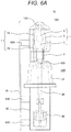
- the switch unit 70 (switch for a high-voltage pull-through cable) according to this embodiment will be described in detail referring to the top view of Fig. 3 and the side view of Fig. 6A .
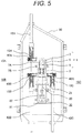
- the switch unit 70 mainly includes a vacuum interrupter 1 which functions as a switch to make a cable connected on the fixed side and a cable connected on the movable side come into or out of contact with each other and an electromagnetic operation device 30 which functions as an operation mechanism to generate a driving force required to make the cables come into or out of contact, in which these components are disposed in alignment with each other.
- the electromagnetic operation device 30 combines a permanent magnet and an electromagnet with a spring to generate a driving force by turning ON or OFF the power to the coil of the electromagnet, in which these magnets are covered by a mechanism case 82.
- the fixed electrode 3 of the vacuum interrupter 1 is electrically connected to a bushing conductor 12A through a fixed conductor pulled out of the vacuum interrupter 1.
- the movable electrode 5 is electrically connected to bushing conductors 12B and 12C through a movable conductor pulled out of the vacuum interrupter 1 and controlled by an aerial insulating operation rod 20 driven by the electromagnetic operation device 30 so that the movable electrode 5 comes into or out of the fixed electrode 3.
- the bushing conductors 12A, 12B, and 12C and the insulator of an insulating case 21 are combined to form bushings 10A, 10B, and 10C. Due to this structure, the bushing 10A on the fixed side can be separated from the bushings 10B and 10C on the movable side.
- the bellows 2 is located between a movable conductor and a movable side end plate so that the movable conductor can move while the vacuum state of the vacuum interrupter 1 is maintained.
- the overall height and overall width of the switch unit 70 can be smaller and the projected area of the unit as seen in the traveling direction can be smaller than in a conventional switch unit in which the insulating case 21 (vacuum interrupter 1) and the mechanism case 82 (electromagnetic operation device 30) are vertically or horizontally arranged. Consequently, even when the switch unit 70 is installed on the roof 72 of the rail car 100, the resulting increase in air resistance can be suppressed.
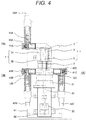
- the T-shaped cable heads 40A, 40B, and 40C are provided with insulating plugs 41A, 41B, and 41C on the opposite side of the connecting ends respectively so that the surface of each of the T-shaped cable heads is kept at the ground potential.
- bushings 10A, 10B, and 10C are disposed virtually perpendicularly to the direction of movement of the movable electrode 5, workability in connecting the T-shaped cable head is improved.
- the switch unit 70 according to a second embodiment will be described referring to the plan view of Fig. 7 . Description of the same components as in the first embodiment is omitted here.
- the switch unit 70 has a function as a straight joint SJ which connects a cable 42A and a cable 42B but does not have a function as a T joint TJ.
- a cable on the movable side cannot be branched but the width of the unit can be smaller than in the first embodiment and when the unit is installed on the roof 72 of the rail car 100, the air resistance can be smaller.
- the switch unit 70 has a function as a straight joint SJ which connects the cable 42A and cable 42B, a function as a T joint TJ which branches the cable 42C on the movable side, and a function as a T joint TJ which branches the cable 42D (not shown) on the fixed side.
- cables can be branched not only on the movable side but also on the fixed side, so the range of choices of circuit configuration is expanded.
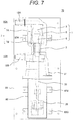
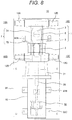
- the aerial insulating operation rod 20 and electromagnetic operation device 30 are disposed out of alignment and connected to each other through a link 84 as shown in Fig. 9 .
- the link 84 which functions as a lever, enables the vacuum interrupter 1 to operate properly, so the electromagnetic operation device 30 and the vacuum interrupter 1 can be selected independently. Furthermore, adjustment workability is improved.
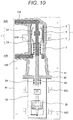
- a bellows 2A which seals an insulating gas between the aerial insulating operation rod 20 and the flange 85 is added to the structure shown in Fig. 3 , etc.
- the vacuum interrupter 1 When the vacuum interrupter 1 is in its closed state, as the electromagnetic operation device 30 is activated to move the movable electrode 5 away from the fixed electrode 3, the bellows 2 on the movable electrode 5 side compresses and the bellows 2A on the opposite side expands, which decreases the internal space of the bellows 2 and increases the internal space of the bellows 2A.
- the electromagnetic operation device 30 is activated to move the movable electrode 5 away from the fixed electrode 3
- the bellows 2 on the movable electrode 5 side compresses and the bellows 2A on the opposite side expands, which decreases the internal space of the bellows 2 and increases the internal space of the bellows 2A.
- the diameter of the bellows 2 is virtually equal to the diameter of the bellows 2A and the amount of compression of the bellows 2, disposed coaxially with the bellows 2A, is equal to the amount of expansion of the bellows 2A, and thus the amount of decrease in volume due to the compression of the bellows 2 is virtually equal to the amount of increase in volume due to the expansion of the bellows 2A.
- the vacuum interrupter 1 when the vacuum interrupter 1 is switched from the closed state to the open state, the space around the aerial insulating operation rod 20 sandwiched between both the bellows neither increases nor decreases.
- the vacuum interrupter 1 is switched from the open state to the closed state, again the space around the aerial insulating operation rod 20 sandwiched between both the bellows neither increases nor decreases.
Landscapes
- Engineering & Computer Science (AREA)
- Mechanical Engineering (AREA)
- Transportation (AREA)
- Power Engineering (AREA)
- Fittings On The Vehicle Exterior For Carrying Loads, And Devices For Holding Or Mounting Articles (AREA)
- Gas-Insulated Switchgears (AREA)
- Electric Propulsion And Braking For Vehicles (AREA)
- High-Tension Arc-Extinguishing Switches Without Spraying Means (AREA)
- Current-Collector Devices For Electrically Propelled Vehicles (AREA)
Applications Claiming Priority (1)
| Application Number | Priority Date | Filing Date | Title |
|---|---|---|---|
| JP2016184980A JP2018049764A (ja) | 2016-09-23 | 2016-09-23 | 開閉器ユニット、および、それを用いた鉄道車両 |
Publications (1)
| Publication Number | Publication Date |
|---|---|
| EP3300096A1 true EP3300096A1 (en) | 2018-03-28 |
Family
ID=59383503
Family Applications (1)
| Application Number | Title | Priority Date | Filing Date |
|---|---|---|---|
| EP17182416.2A Withdrawn EP3300096A1 (en) | 2016-09-23 | 2017-07-20 | Switch unit and rail car using the same |
Country Status (3)
| Country | Link |
|---|---|
| EP (1) | EP3300096A1 (enExample) |
| JP (1) | JP2018049764A (enExample) |
| CN (1) | CN107867184A (enExample) |
Cited By (1)
| Publication number | Priority date | Publication date | Assignee | Title |
|---|---|---|---|---|
| EP3926650A1 (fr) * | 2020-06-17 | 2021-12-22 | ALSTOM Transport Technologies | Dispositif de commutation, ensemble associé et véhicule comportant un tel ensemble |
Families Citing this family (1)
| Publication number | Priority date | Publication date | Assignee | Title |
|---|---|---|---|---|
| WO2021140668A1 (ja) * | 2020-01-10 | 2021-07-15 | 三菱電機株式会社 | 真空遮断器 |
Citations (3)
| Publication number | Priority date | Publication date | Assignee | Title |
|---|---|---|---|---|
| US20020044036A1 (en) * | 2000-10-16 | 2002-04-18 | Hiroyuki Akita | Switching device |
| EP2664481A1 (en) * | 2011-01-14 | 2013-11-20 | Kawasaki Jukogyo Kabushiki Kaisha | Circuit breaker unit, and rolling stock provided therewith |
| US20150206683A1 (en) * | 2013-09-10 | 2015-07-23 | Kabushiki Kaisha Toshiba | Switchgear |
Family Cites Families (5)
| Publication number | Priority date | Publication date | Assignee | Title |
|---|---|---|---|---|
| FR2753834B1 (fr) * | 1996-09-23 | 1998-12-04 | Disjoncteur a haute tension avec amortisseur | |
| JP4906892B2 (ja) * | 2009-08-12 | 2012-03-28 | 株式会社日立製作所 | スイッチギヤ |
| CN103050320A (zh) * | 2011-05-13 | 2013-04-17 | 中煤电气有限公司 | 一种小型化大电流手车式真空断路器 |
| JP6216529B2 (ja) * | 2013-03-28 | 2017-10-18 | 株式会社日立産機システム | 鉄道車両 |
| JP2015043656A (ja) * | 2013-08-26 | 2015-03-05 | 株式会社東芝 | 開閉器 |
-
2016
- 2016-09-23 JP JP2016184980A patent/JP2018049764A/ja active Pending
-
2017
- 2017-07-20 EP EP17182416.2A patent/EP3300096A1/en not_active Withdrawn
- 2017-08-31 CN CN201710766971.0A patent/CN107867184A/zh active Pending
Patent Citations (4)
| Publication number | Priority date | Publication date | Assignee | Title |
|---|---|---|---|---|
| US20020044036A1 (en) * | 2000-10-16 | 2002-04-18 | Hiroyuki Akita | Switching device |
| EP2664481A1 (en) * | 2011-01-14 | 2013-11-20 | Kawasaki Jukogyo Kabushiki Kaisha | Circuit breaker unit, and rolling stock provided therewith |
| JP5486695B2 (ja) | 2011-01-14 | 2014-05-07 | 川崎重工業株式会社 | 回路遮断ユニットおよびそれを備えた鉄道車両 |
| US20150206683A1 (en) * | 2013-09-10 | 2015-07-23 | Kabushiki Kaisha Toshiba | Switchgear |
Cited By (2)
| Publication number | Priority date | Publication date | Assignee | Title |
|---|---|---|---|---|
| EP3926650A1 (fr) * | 2020-06-17 | 2021-12-22 | ALSTOM Transport Technologies | Dispositif de commutation, ensemble associé et véhicule comportant un tel ensemble |
| FR3111733A1 (fr) * | 2020-06-17 | 2021-12-24 | Alstom Transport Technologies | Dispositif de commutation, ensemble associé et véhicule comportant un tel ensemble |
Also Published As
| Publication number | Publication date |
|---|---|
| JP2018049764A (ja) | 2018-03-29 |
| CN107867184A (zh) | 2018-04-03 |
Similar Documents
| Publication | Publication Date | Title |
|---|---|---|
| JP6328998B2 (ja) | ユニット開閉器及び開閉装置並びに鉄道車両 | |
| US20110036811A1 (en) | Switchgear and Method for Operating Switchgear | |
| CN106165046B (zh) | 复合型开闭器 | |
| CN104247184A (zh) | 开闭装置 | |
| KR101736290B1 (ko) | 철도 차량 | |
| EP3300096A1 (en) | Switch unit and rail car using the same | |
| JP6713940B2 (ja) | 固体絶縁型開閉器ユニットの放熱装置、固体絶縁型開閉器ユニット、および、鉄道車両 | |
| EP3364438B1 (en) | Rail car switch unit | |
| US10589760B2 (en) | Branching unit and vehicular system | |
| JP6783720B2 (ja) | 真空開閉装置 | |
| JP6951201B2 (ja) | 開閉器ユニット及びこれを用いた鉄道車両 | |
| EP3770938B1 (en) | Solid dielectric vacuum switchgear | |
| JP7576190B2 (ja) | 開閉器 |
Legal Events
| Date | Code | Title | Description |
|---|---|---|---|
| PUAI | Public reference made under article 153(3) epc to a published international application that has entered the european phase |
Free format text: ORIGINAL CODE: 0009012 |
|
| STAA | Information on the status of an ep patent application or granted ep patent |
Free format text: STATUS: REQUEST FOR EXAMINATION WAS MADE |
|
| 17P | Request for examination filed |
Effective date: 20171106 |
|
| AK | Designated contracting states |
Kind code of ref document: A1 Designated state(s): AL AT BE BG CH CY CZ DE DK EE ES FI FR GB GR HR HU IE IS IT LI LT LU LV MC MK MT NL NO PL PT RO RS SE SI SK SM TR |
|
| AX | Request for extension of the european patent |
Extension state: BA ME |
|
| RBV | Designated contracting states (corrected) |
Designated state(s): AL AT BE BG CH CY CZ DE DK EE ES FI FR GB GR HR HU IE IS IT LI LT LU LV MC MK MT NL NO PL PT RO RS SE SI SK SM TR |
|
| STAA | Information on the status of an ep patent application or granted ep patent |
Free format text: STATUS: EXAMINATION IS IN PROGRESS |
|
| 17Q | First examination report despatched |
Effective date: 20200305 |
|
| STAA | Information on the status of an ep patent application or granted ep patent |
Free format text: STATUS: THE APPLICATION IS DEEMED TO BE WITHDRAWN |
|
| 18D | Application deemed to be withdrawn |
Effective date: 20200716 |