EP3299714A1 - Combustion burner and boiler provided with same - Google Patents
Combustion burner and boiler provided with same Download PDFInfo
- Publication number
- EP3299714A1 EP3299714A1 EP16844082.4A EP16844082A EP3299714A1 EP 3299714 A1 EP3299714 A1 EP 3299714A1 EP 16844082 A EP16844082 A EP 16844082A EP 3299714 A1 EP3299714 A1 EP 3299714A1
- Authority
- EP
- European Patent Office
- Prior art keywords
- splitters
- slitted
- fuel gas
- fuel
- gas flow
- Prior art date
- Legal status (The legal status is an assumption and is not a legal conclusion. Google has not performed a legal analysis and makes no representation as to the accuracy of the status listed.)
- Withdrawn
Links
- 238000002485 combustion reaction Methods 0.000 title claims abstract description 50
- 239000002737 fuel gas Substances 0.000 claims abstract description 69
- 239000000446 fuel Substances 0.000 claims description 87
- 238000011144 upstream manufacturing Methods 0.000 description 15
- 239000003245 coal Substances 0.000 description 9
- 230000002093 peripheral effect Effects 0.000 description 7
- 230000000694 effects Effects 0.000 description 4
- QVGXLLKOCUKJST-UHFFFAOYSA-N atomic oxygen Chemical compound [O] QVGXLLKOCUKJST-UHFFFAOYSA-N 0.000 description 3
- 239000001301 oxygen Substances 0.000 description 3
- 229910052760 oxygen Inorganic materials 0.000 description 3
- 230000015572 biosynthetic process Effects 0.000 description 2
- 230000005855 radiation Effects 0.000 description 2
- 239000002028 Biomass Substances 0.000 description 1
- 230000000903 blocking effect Effects 0.000 description 1
- 230000007812 deficiency Effects 0.000 description 1
- 238000000034 method Methods 0.000 description 1
- 230000004048 modification Effects 0.000 description 1
- 238000012986 modification Methods 0.000 description 1
- 239000002006 petroleum coke Substances 0.000 description 1
- 239000003209 petroleum derivative Substances 0.000 description 1
- 238000010298 pulverizing process Methods 0.000 description 1
- 239000002002 slurry Substances 0.000 description 1
- 239000007787 solid Substances 0.000 description 1
Images


Classifications
-
- F—MECHANICAL ENGINEERING; LIGHTING; HEATING; WEAPONS; BLASTING
- F23—COMBUSTION APPARATUS; COMBUSTION PROCESSES
- F23D—BURNERS
- F23D1/00—Burners for combustion of pulverulent fuel
-
- F—MECHANICAL ENGINEERING; LIGHTING; HEATING; WEAPONS; BLASTING
- F23—COMBUSTION APPARATUS; COMBUSTION PROCESSES
- F23D—BURNERS
- F23D23/00—Assemblies of two or more burners
-
- F—MECHANICAL ENGINEERING; LIGHTING; HEATING; WEAPONS; BLASTING
- F24—HEATING; RANGES; VENTILATING
- F24H—FLUID HEATERS, e.g. WATER OR AIR HEATERS, HAVING HEAT-GENERATING MEANS, e.g. HEAT PUMPS, IN GENERAL
- F24H9/00—Details
- F24H9/18—Arrangement or mounting of grates or heating means
- F24H9/1809—Arrangement or mounting of grates or heating means for water heaters
- F24H9/1832—Arrangement or mounting of combustion heating means, e.g. grates or burners
- F24H9/1845—Arrangement or mounting of combustion heating means, e.g. grates or burners using solid fuel
-
- F—MECHANICAL ENGINEERING; LIGHTING; HEATING; WEAPONS; BLASTING
- F23—COMBUSTION APPARATUS; COMBUSTION PROCESSES
- F23D—BURNERS
- F23D2201/00—Burners adapted for particulate solid or pulverulent fuels
- F23D2201/10—Nozzle tips
-
- F—MECHANICAL ENGINEERING; LIGHTING; HEATING; WEAPONS; BLASTING
- F23—COMBUSTION APPARATUS; COMBUSTION PROCESSES
- F23D—BURNERS
- F23D2201/00—Burners adapted for particulate solid or pulverulent fuels
- F23D2201/20—Fuel flow guiding devices
Definitions
- the present disclosure relates to a combustion burner and a boiler equipped with the same.
- a combustion burner for combusting pulverized coal fuel there is known a burner where a plurality of flame holders, which are referred to as “splitters”, are disposed at an outlet of a fuel nozzle of the burner.
- a recirculation region is formed on a downstream side of the splitters to maintain combustion of pulverized coal.
- ignition and flame holding hereinafter referred to as “internal ignition” or “internal flame holding" are performed in the vicinity of a center axis of the fuel nozzle so that reduced combustion is performed under an air deficiency condition to realize low NOx combustion.
- a flame holder have a long edge length of splitter length.
- a blocking rate of an outlet of a burner and hence, pressure loss of the burner is increased.
- the splitters are disposed close to a wall portion of the fuel nozzle and hence, there is a possibility that ignition occurs at an outer periphery of the fuel nozzle.
- a combustion air supply nozzle and the like are disposed outside the fuel nozzle so that a large amount of oxygen is present, and therefore when external ignition occurs, there is a risk that a large amount of NOx is generated.
- PTL 1 and PTL 2 disclose combustion burners where splitters are formed into a comb shape when the splitters are viewed in a front view from the downstream side.
- the splitter described in PTL 1 is configured to introduce pulverized coal to the outer peripheral side of a nozzle so that external ignition is performed. Accordingly, low NOx combustion cannot be realized with such a configuration.
- the present disclosure is made under such circumstances, and it is an object of the present disclosure to provide a combustion burner where an edge length of splitter length of a splitter is increased and flame holding performance is enhanced so that low NOx combustion can be realized by internal flame holding, and a boiler equipped with the same.
- a combustion burner which includes: a fuel nozzle through which a fuel gas obtained by mixing a fuel and air with each other is blown into a furnace; and a plurality of splitters configured to divide a fuel gas flow by a widened portion where a width of the widened portion increases as the widened portion extends in a direction of the fuel gas flow, the splitters being disposed in the fuel nozzle on a distal end side of the fuel nozzle such that longitudinal axes of the splitters extend from a side of one wall portion of the fuel nozzle to a side of the other wall portion which is disposed on a side opposite to said one wall portion, wherein the plurality of splitters include: a slitted splitters configured to slit which partially reduces a width of the widened portion at a downstream end in the fuel gas flow, and a non-slitted splitters configured to adjacently to the slitted splitters, the non-slitted splitters having the
- the slitted splitter has the slit so that an edge length of splitter length of the slitted splitter is increased whereby flame holding performance is enhanced. Accordingly, internal flame holding where a flame is held on the inside of the fuel nozzle is strengthened.
- the non-slitted splitter forms a recirculation region on the downstream of the widened portion and thus has a flame holding function, but also has a function as a guide member which guides a fuel to the slitted splitter disposed adjacently to the non-slitted splitter by making use of inclined surfaces of the widened portion. Accordingly, internal flame holding by the slitted splitter is further strengthened.
- a combustion burner which includes: a fuel nozzle through which a fuel gas obtained by mixing a fuel and air with each other is blown into a furnace; and a plurality of splitters configured to divide a fuel gas flow by a widened portion where a width of the widened portion increases as the widened portion extends in a direction of the fuel gas flow, the splitters being disposed in the fuel nozzle on a distal end side of the fuel nozzle such that longitudinal axes of the splitters extend from a side of one wall portion of the fuel nozzle to a side of the other wall portion which is disposed on a side opposite to said one wall portion, wherein the splitter includes a plurality of slitted splitters having a slit which partially reduces a width of the widened portion at a downstream end in the fuel gas flow, and the slitted splitters disposed adjacently to each other respectively include wide surfaces having no slit, and the wide surfaces of the widened
- the slitted splitters are disposed adjacently to each other, and the wide surfaces having no slit oppositely face each other so that a fuel guided by the wide surface of one splitter is introduced to a downstream side of the other splitter. In this way, a fuel is guided between the wide surfaces disposed adjacently to each other in an oppositely facing manner so that flame holding is strengthened on both splitters.
- the splitter does not inject air and hence, there is no possibility that a flow of the guided fuel is inhibited.
- a surface forming the slit of the slitted splitter may be formed of an inclined surface which deflects the fuel gas flow in the direction of the longitudinal axis.
- the inclined surface forming the slit deflects the fuel gas flow in the direction of the longitudinal axis of the splitter. Accordingly, the fuel gas flow can become turbulent also in the direction of the longitudinal axis and hence, flame holding performance can be further enhanced.
- the slit can be three-dimensionally formed by respective surfaces forming the slit and hence, flame holding performance can be enhanced.
- the splitters may be disposed at different positions in the direction of the fuel gas flow.
- the splitters are disposed at different positions in the direction of the fuel gas flow, that is, the splitters are disposed in a displaced manner toward the upstream side and toward the downstream side in the direction of the fuel gas flow. Accordingly, compared to a case where the splitters are disposed at the same position in the direction of the fuel gas flow, an area which the widened portions of the splitters occupy can be reduced.
- an increase in speed of a fuel gas can be suppressed so that a flow speed of a fuel gas toward the downstream side in the direction of the fuel gas flow can be approximated to a combustion speed of a fuel gas toward the upstream side so that ignition can be performed at an early stage before the fuel gas further flows toward the downstream side and hence, flame holding performance of the flame can be enhanced.
- Ignition can be performed at the early stage by the splitters positioned on the upstream side in the fuel gas flow, and ignition or flame holding can be strengthened by the splitters positioned on the downstream side in the fuel gas flow.
- the splitters positioned on the upstream side in the fuel gas flow can introduce a fuel to the recirculation region for the splitters on the downstream side so that ignition or flame holding by the splitters on the downstream side can be strengthened.
- the non-slitted splitters be disposed on the upstream side, and the slitted splitters be disposed on the downstream side.
- a flow straightening plate which is configured to separate a wall surface side of the fuel nozzle and the splitter from each other may be disposed at an end portion of the splitter in the longitudinal direction.
- the flow straightening plate which separates the wall surface side of the fuel nozzle and the splitter from each other. Accordingly, external ignition, where ignition is performed at the end portion of the splitter, can be suppressed so that internal ignition and flame holding can be further strengthened.
- the splitter may have a corner-removed portion, where a corner portion is removed, at a downstream end corner portion of the widened portion.
- a splitter has an corner portion at the downstream end corner portion of the widened portion, there is a possibility that the splitter receives radiation from the inner peripheral surface side of the fuel nozzle so that ignition occurs using the corner portion as a starting point whereby external ignition occurs at the outer peripheral portion of the fuel nozzle.
- a combustion air supply nozzle and the like are disposed outside the fuel nozzle so that a large amount of oxygen is present. Accordingly, when external ignition occurs, a large amount of NOx is generated.
- the corner portion-removed portion where the corner portion is removed, is formed on the splitter so as to suppress ignition or flame holding.
- a tapered portion where a corner portion is chamfered can be named, for example.
- a boiler which includes: a furnace; any one of the above-described combustion burners provided in the furnace; a flue provided on a downstream side of the furnace; and a heat exchanger provided in the flue.
- an edge length of splitter length of the splitter on a front surface can be increased and, at the same time, a fuel can be guided to a recirculation region which is formed by the adjacent splitter, whereby flame holding performance at a center region of the fuel nozzle is enhanced, and low NOx combustion brought about by internal flame holding can be realized.
- a combustion burner of this embodiment combusts a pulverized coal fuel (fuel) obtained by pulverizing mainly coal by a mill, and is provided in a boiler (not shown in the drawing).
- a plurality of combustion burners are provided for the boiler which includes heat exchange such as a superheater and an evaporator in a flue, and the combustion burners form flames in a furnace.
- Fig. 1 is a front view of a combustion burner 1.
- the combustion burner 1 includes: a fuel nozzle 3 positioned on the inner side; and a combustion air supply nozzle 4 surrounding the fuel nozzle 3.
- the combustion air supply nozzle 4 forms a flow passage through which only a secondary air passes. Air is supplied through the combustion air supply nozzle 4 such that the air travels in a straight line toward the inside of the furnace. That is, air flowing out from the combustion air supply nozzle 4 is made to flow parallel to a fuel gas flowing out from the fuel nozzle 3 so as not to intersect with the fuel gas flowing out from the fuel nozzle 3.
- a tertiary combustion air nozzle through which combustion air is supplied, is disposed outside the combustion air supply nozzle 4.
- the fuel nozzle 3 has a rectangular cross section as viewed in a front view, and a fuel gas obtained by mixing pulverized coal and air with each other is made to flow through the inside of the fuel nozzle 3.
- a fuel gas obtained by mixing pulverized coal and air with each other is made to flow through the inside of the fuel nozzle 3.
- downstream side in a fuel gas flow is simply referred to as “downstream side”
- upstream side is simply referred to as "upstream side”.
- a plurality of splitters 5, 6, 7 are disposed in the fuel nozzle 3, and five splitters are disposed in this embodiment.
- Each of the splitters 5, 6, 7 is disposed such that a longitudinal axis thereof extends from the side of a lower wall portion (one wall portion) 3a of the fuel nozzle 3 to the side of an upper wall portion (the other wall portion) 3b which is disposed on a side opposite to the lower wall portion 3a. That is, each of the splitters 5, 6, 7 is a vertical splitter which is disposed so as to extend in the vertical direction.
- Upper and lower ends of the splitters 5, 6, 7 are fixed to wall portions of the fuel nozzle 3 by support members 8 respectively.
- the fuel nozzle 3 includes a nozzle angle adjusting mechanism which is rotatable in the up-and-down direction together with the splitters 5, 6, 7.
- vertical splitters are used so that even when an angle of the nozzle is adjusted in the up-and-down direction, a flow of a fuel gas is not largely deflected, which is preferable.
- the splitters 5, 6, 7 are members having a function of dividing a fuel gas flow, but do not have a function of injecting air from the inside.
- the splitters include: slitted splitters 5 and 6 disposed in the center and on both ends in the horizontal direction; and non-slitted splitters 7 adjacently disposed on both sides of the slitted splitter 5 disposed in the center. In this way, each non-slitted splitter 7 is disposed at a position where the non-slitted splitter 7 is disposed adjacently to the slitted splitters 5, 6.
- the splitters 5, 6, 7 include a widened portion 10 where a width of the widened portion 10 is increased as the widened portion 10 extends in the direction of the fuel gas flow. Further, a plate-shaped portion 11 which extends in the up-and-down direction is disposed on the upstream side of the widened portion 10 along the direction of the fuel gas flow.
- the widened portions 10 have an approximately triangular shape as shown in Fig. 2 as viewed in a cross-sectional view.
- the widened portion 10 of the slitted splitter 5 disposed at the center and the widened portion 10 of the non-slitted splitter 7 respectively have a shape where a width of the widened portion 10 is increased toward both sides as shown in Fig. 2 as viewed in a cross-sectional view.
- the widened portion 10 of the slitted splitter 6 positioned at both ends in the horizontal direction has a shape where a width of the widened portion 10 is increased toward the center side of the fuel nozzle 3 but is not increased toward the wall portion side of the fuel nozzle 3.
- the downstream side of the slitted splitter 6 positioned on both sides is formed into a straight line shape so that a fuel gas which flows between the wall surface of the fuel nozzle 3 and the slitted splitter 6 is prevented from deflecting toward the side of a flow of air flowing out from the combustion air supply nozzle 4.
- external ignition which occurs on the outer peripheral side of the fuel nozzle 3 can be suppressed.
- downstream ends 5a, 6a of the slitted splitters 5, 6 are aligned at a position of a downstream end 3c of the fuel nozzle 3.
- Downstream ends 7a of the non-slitted splitters 7 are disposed at a predetermined distance S toward the upstream side from the downstream ends 5a, 6a of the slitted splitters 5, 6.
- the predetermined distance S is set to 0.001D or more and 1.0D or less, and more preferably set to 0.03D or more and 0.5D or less. It is further preferable to set the predetermined distance S to 0.05D or more and 0.3D or less.
- a lower limit value and an upper limit value of the predetermined distance S is determined based on the following viewpoint.
- the predetermined distance S becomes lower than the lower limit value, a distance between the slitted splitters 5, 6 and the non-slitted splitters 7 becomes extremely small. Accordingly, even when these splitters are displaced from each other so as to ensure a sufficient cross-sectional area of a flow passage, an advantageous effect of such a configuration cannot be obtained.
- the predetermined distance S may be adjusted by moving the non-slitted splitters 7 positioned on the upstream side in the direction of the fuel gas flow as indicated by arrows A in Fig. 2 .
- the non-slitted splitters 7 are formed such that the downstream ends 7a have a fixed width in the direction of the longitudinal axis (an axis in the vertical direction) of the non-slitted splitters 7.
- the slitted splitter 5 disposed in the center has a plurality of slits SL each of which partially reduces a width of the downstream end 5a.
- the slitted splitter 5 disposed in the center has the slits SL on both side portions thereof at the same height position. With the formation of these slits, the slitted splitter 5 has wide portions W1 and narrow portions W2.
- Fig. 3 specifically shows a shape of the slits SL.
- Each slit SL is formed by notching the downstream end 5a of the slitted splitter 5 in a U shape.
- an upper surface SL1 and a lower surface SL2 forming the slit SL form surfaces which deflect a fuel gas flow in the direction of the longitudinal axis of the splitter 5 (the up-and-down direction in this embodiment). That is, the upper surface SL1 deflects the fuel gas flow in the downward direction, and the lower surface SL2 deflects the fuel gas flow in the upward direction.
- the slitted splitter 6 disposed at both ends also has slits SL substantially equal to the slits SL formed on the slitted splitter 5 disposed at the center.
- the slits SL are formed only on a side of each slitted splitter 6 on the center side of the fuel nozzle 3. This is because when the slits SL are formed also on a side of each slitted splitter 6 on the wall portion side of the fuel nozzle 3, there is a possibility that the slits SL form ignition surfaces to cause external ignition.
- the slits SL be formed at a center portion of the splitters 5, 6 in the longitudinal direction so as to allow ignition or flame holding to be performed at a position as close as possible to the center side of the fuel nozzle 3, and that the slits SL be not formed at both upper and lower end portions of the splitters 5, 6.
- a range L 1 where the slits SL are formed is set such that an expression L 1 /L 0 becomes 0.8 or less, and is preferably 0.5 or less.
- flow straightening plates 15 each separating these splitters 5, 6, 7 and the wall portion of the fuel nozzle 3 from each other are formed on upper and lower ends of the splitters 5, 6, 7 in the longitudinal axis. Accordingly, the flow straightening plate 15 disposed on the upper side separates a fuel gas flowing on the side of the splitters 5, 6, 7 and a fuel gas flowing on the side of the upper wall portion 3b of the fuel nozzle 3 from each other. The flow straightening plate 15 disposed on the lower side separates a fuel gas flowing on the side of the splitters 5, 6, 7 and a fuel gas flowing on the side of the lower wall portion 3a of the fuel nozzle 3 from each other.
- the non-slitted splitters 7 form a recirculation region on the downstream of the widened portion 10 and thus have a flame holding function, but also have a function as a guide member which guides fuel to the slitted splitters 5, 6 disposed adjacently to the non-slitted splitters 7 by making use of the inclined surfaces of the widened portion 10. Accordingly, internal flame holding by the slitted splitters 5, 6 is further strengthened. In this way, internal flame holding is strengthened by the combination of the slitted splitters 5, 6 and the non-slitted splitters 7 so that reduced combustion is promoted whereby NOx generated in a flame region of the burner can be reduced.
- the upper surface SL1 and the lower surface SL2 which are the inclined surfaces forming the slit SL deflect a fuel gas flow in the direction of the longitudinal axis of the splitters 5, 6. Accordingly, the fuel gas flow can become turbulent also in the direction of the longitudinal axis and hence, flame holding performance can be further enhanced.
- the slit SL can be three-dimensionally formed by respective surfaces forming the slit SL and hence, flame holding performance can be enhanced.
- the splitters 5, 6, 7 are disposed at different positions in the direction of the fuel gas flow. Accordingly, compared to a case where the splitters 5, 6, 7 are disposed at the same position in the direction of the fuel gas flow, an area occupied by the widened portions 10 of the splitters can be reduced. With such a configuration, an increase in speed of a fuel gas can be suppressed so that a flow speed of a fuel gas toward the downstream side in the direction of the fuel gas flow can be approximated to a combustion speed of a fuel gas toward the upstream side, ignition can be performed at an early stage before the fuel gas further flows toward the downstream side, and hence, flame holding performance of the flame can be enhanced.
- the non-slitted splitters 7 positioned on the upstream side in the fuel gas flow guide a fuel to the recirculation region for the slitted splitters 5, 6 on the downstream side so that ignition or flame holding by the slitted splitters 5, 6 on the downstream side can be strengthened.
- a main function of a splitter is to guide pulverized coal, it is preferable to use the non-slitted splitter 7 as the splitter.
- the non-slitted splitters 7 are disposed on the upstream side, and the slitted splitters 5, 6 are disposed on the downstream side, but the non-slitted splitters 7 and the slitted splitters 5, 6 may be disposed in a reversed arrangement, that is, the non-slitted splitters 7 may be disposed on the downstream side, and the slitted splitters 5, 6 may be disposed on the upstream side.
- This configuration is adopted when a fuel is used which is expected to ignite at an early stage. Ignition is performed at the early stage by the slitted splitters 5, 6 disposed on the upstream side, and the non-slitted splitters guide a fuel gas to a recirculation region formed by these slitted splitters 5, 6.
- all splitters may be formed of the slitted splitters 5, 6.
- the slitted splitters 5, 6 are disposed adjacently to each other, and the wide portions W1 having no slit SL oppositely face each other so that a fuel guided by the wide surface of one splitter is introduced to the downstream side of the other splitter.
- a fuel is guided between the wide portions W1 disposed adjacently to each other in an oppositely facing manner so that flame holding is strengthened on both splitters.
- This embodiment differs from the first embodiment with respect to a point that tapered portions, where corner portions of the splitters 6 are removed, are formed on the splitters 6, and is the same in other respects. Accordingly, components in common are given the same reference numerals, and description thereof is omitted.
- each of the slitted splitters 6 disposed at both ends has a tapered portion (corner-removed portion) 20 at upper and lower corner portions thereof on the center-portion-side of the fuel nozzle 3.
- the tapered portion 20 may have any shape provided that the corner portion is removed. As shown in Fig. 6 , it is sufficient for the tapered portion 20 to have a shape where respective vertex angles ⁇ 1, ⁇ 2, ⁇ 3 of three surfaces forming the corner portion are removed. Accordingly, the tapered portion 20 may be formed of a flat surface such as a tapered surface or may be formed of a curved surface.
- two flow straightening plates 15a, 15b are provided.
- the respective flow straightening plates 15a, 15b are disposed at height positions symmetrical with each other with respect to a center position of the fuel nozzle 3 in the height direction, and are formed of plate bodies extending in the horizontal direction.
- the tapered portion 20, where the corner portion is removed is formed so that it is possible to suppress a phenomenon that the splitter 6 receives radiation from the inner peripheral surface side of the fuel nozzle 3 so that ignition occurs at the corner portion as a starting point whereby external ignition occurs at an outer peripheral portion of the fuel nozzle 3.
- the tapered portion (corner-removed portion) 20 may be also formed on other splitters. That is, the tapered portion 20 may be also formed on the slitted splitter 5 disposed at the center or on the non-slitted splitters 7.
- five splitters are used.
- the present disclosure is not limited to such a configuration. Two to four splitters may be used, or six or more splitters may be used. The optimum number of splitters is designed depending on a size of a fuel nozzle.
- the description is made with respect to a case where the splitters 5, 6, 7 are vertical splitters extending in the up-and-down direction as one example.
- the present disclosure is also applicable to a case where the splitters 5, 6, 7 are lateral splitters extending in the horizontal direction.
- the fuel is not limited to pulverized coal, and the present disclosure is also applicable to a case where the fuel is petroleum coke, a petroleum residue or a biomass fuel (in the form of a solid or slurry).
Landscapes
- Engineering & Computer Science (AREA)
- Chemical & Material Sciences (AREA)
- Combustion & Propulsion (AREA)
- Mechanical Engineering (AREA)
- General Engineering & Computer Science (AREA)
- Physics & Mathematics (AREA)
- Thermal Sciences (AREA)
- Combustion Of Fluid Fuel (AREA)
- Gas Burners (AREA)
Abstract
Description
- The present disclosure relates to a combustion burner and a boiler equipped with the same.
- As a combustion burner for combusting pulverized coal fuel, there is known a burner where a plurality of flame holders, which are referred to as "splitters", are disposed at an outlet of a fuel nozzle of the burner. In the burner, a recirculation region is formed on a downstream side of the splitters to maintain combustion of pulverized coal. In this manner, ignition and flame holding (hereinafter referred to as "internal ignition" or "internal flame holding") are performed in the vicinity of a center axis of the fuel nozzle so that reduced combustion is performed under an air deficiency condition to realize low NOx combustion.
- To enhance flame holding performance, it is preferable that a flame holder have a long edge length of splitter length. However, when the number of splitters is increased, a blocking rate of an outlet of a burner and hence, pressure loss of the burner is increased. Further, even when the number of splitters is increased while reducing a width of the splitters so as to ensure the edge length of splitter length, the splitters are disposed close to a wall portion of the fuel nozzle and hence, there is a possibility that ignition occurs at an outer periphery of the fuel nozzle. A combustion air supply nozzle and the like are disposed outside the fuel nozzle so that a large amount of oxygen is present, and therefore when external ignition occurs, there is a risk that a large amount of NOx is generated.
- The following PTL 1 and PTL 2 disclose combustion burners where splitters are formed into a comb shape when the splitters are viewed in a front view from the downstream side.
-
- {PTL 1} Japanese Unexamined Patent Application, Publication No.
Sho 59-205510 - {PTL 2} Japanese Unexamined Patent Application, Publication No.
2009-204256 - When the splitters are formed into a comb shape as described in the above-mentioned respective patent literatures, an edge length of splitter length can be ensured.
- However, the splitter described in PTL 1 is configured to introduce pulverized coal to the outer peripheral side of a nozzle so that external ignition is performed. Accordingly, low NOx combustion cannot be realized with such a configuration.
- In the technique disclosed in PTL 2, air is injected from the splitter. Accordingly, combustion performed in a fuel nozzle is promoted so that reduced combustion is inhibited and hence, low NOx combustion cannot be realized.
- The present disclosure is made under such circumstances, and it is an object of the present disclosure to provide a combustion burner where an edge length of splitter length of a splitter is increased and flame holding performance is enhanced so that low NOx combustion can be realized by internal flame holding, and a boiler equipped with the same.
- To solve the problems described above, a combustion burner and a boiler equipped with the same according to the present disclosure adopt the following solutions.
- That is, according to one aspect of the present disclosure, there is provided a combustion burner which includes: a fuel nozzle through which a fuel gas obtained by mixing a fuel and air with each other is blown into a furnace; and a plurality of splitters configured to divide a fuel gas flow by a widened portion where a width of the widened portion increases as the widened portion extends in a direction of the fuel gas flow, the splitters being disposed in the fuel nozzle on a distal end side of the fuel nozzle such that longitudinal axes of the splitters extend from a side of one wall portion of the fuel nozzle to a side of the other wall portion which is disposed on a side opposite to said one wall portion, wherein the plurality of splitters include: a slitted splitters configured to slit which partially reduces a width of the widened portion at a downstream end in the fuel gas flow, and a non-slitted splitters configured to adjacently to the slitted splitters, the non-slitted splitters having the widened portion, and the widened portion at a downstream end in the fuel gas flow having a fixed width in a direction of the longitudinal axis.
- The slitted splitter has the slit so that an edge length of splitter length of the slitted splitter is increased whereby flame holding performance is enhanced. Accordingly, internal flame holding where a flame is held on the inside of the fuel nozzle is strengthened.
- The non-slitted splitter forms a recirculation region on the downstream of the widened portion and thus has a flame holding function, but also has a function as a guide member which guides a fuel to the slitted splitter disposed adjacently to the non-slitted splitter by making use of inclined surfaces of the widened portion. Accordingly, internal flame holding by the slitted splitter is further strengthened.
- Further, according to another aspect of the present disclosure, there is provided a combustion burner which includes: a fuel nozzle through which a fuel gas obtained by mixing a fuel and air with each other is blown into a furnace; and a plurality of splitters configured to divide a fuel gas flow by a widened portion where a width of the widened portion increases as the widened portion extends in a direction of the fuel gas flow, the splitters being disposed in the fuel nozzle on a distal end side of the fuel nozzle such that longitudinal axes of the splitters extend from a side of one wall portion of the fuel nozzle to a side of the other wall portion which is disposed on a side opposite to said one wall portion, wherein the splitter includes a plurality of slitted splitters having a slit which partially reduces a width of the widened portion at a downstream end in the fuel gas flow, and the slitted splitters disposed adjacently to each other respectively include wide surfaces having no slit, and the wide surfaces of the widened portions of the slitted splitters oppositely face each other.
- The slitted splitters are disposed adjacently to each other, and the wide surfaces having no slit oppositely face each other so that a fuel guided by the wide surface of one splitter is introduced to a downstream side of the other splitter. In this way, a fuel is guided between the wide surfaces disposed adjacently to each other in an oppositely facing manner so that flame holding is strengthened on both splitters.
- Further, the splitter does not inject air and hence, there is no possibility that a flow of the guided fuel is inhibited.
- A surface forming the slit of the slitted splitter may be formed of an inclined surface which deflects the fuel gas flow in the direction of the longitudinal axis.
- The inclined surface forming the slit deflects the fuel gas flow in the direction of the longitudinal axis of the splitter. Accordingly, the fuel gas flow can become turbulent also in the direction of the longitudinal axis and hence, flame holding performance can be further enhanced. Particularly, the slit can be three-dimensionally formed by respective surfaces forming the slit and hence, flame holding performance can be enhanced.
- The splitters may be disposed at different positions in the direction of the fuel gas flow.
- The splitters are disposed at different positions in the direction of the fuel gas flow, that is, the splitters are disposed in a displaced manner toward the upstream side and toward the downstream side in the direction of the fuel gas flow. Accordingly, compared to a case where the splitters are disposed at the same position in the direction of the fuel gas flow, an area which the widened portions of the splitters occupy can be reduced. With such a configuration, an increase in speed of a fuel gas can be suppressed so that a flow speed of a fuel gas toward the downstream side in the direction of the fuel gas flow can be approximated to a combustion speed of a fuel gas toward the upstream side so that ignition can be performed at an early stage before the fuel gas further flows toward the downstream side and hence, flame holding performance of the flame can be enhanced.
- Ignition can be performed at the early stage by the splitters positioned on the upstream side in the fuel gas flow, and ignition or flame holding can be strengthened by the splitters positioned on the downstream side in the fuel gas flow.
- Further, the splitters positioned on the upstream side in the fuel gas flow can introduce a fuel to the recirculation region for the splitters on the downstream side so that ignition or flame holding by the splitters on the downstream side can be strengthened. In this case, it is preferable that the non-slitted splitters be disposed on the upstream side, and the slitted splitters be disposed on the downstream side.
- A flow straightening plate which is configured to separate a wall surface side of the fuel nozzle and the splitter from each other may be disposed at an end portion of the splitter in the longitudinal direction.
- At the end portion of the splitter in the longitudinal direction, there is a possibility that ignition occurs using the end portion as a base point so that external ignition occurs at an outer peripheral portion of the fuel nozzle. A combustion air supply nozzle and the like are disposed outside the fuel nozzle so that a large amount of oxygen is present, which causes a large amount of NOx to be generated when external ignition occurs.
- In view of the above, the flow straightening plate is provided, which separates the wall surface side of the fuel nozzle and the splitter from each other. Accordingly, external ignition, where ignition is performed at the end portion of the splitter, can be suppressed so that internal ignition and flame holding can be further strengthened.
- The splitter may have a corner-removed portion, where a corner portion is removed, at a downstream end corner portion of the widened portion.
- If a splitter has an corner portion at the downstream end corner portion of the widened portion, there is a possibility that the splitter receives radiation from the inner peripheral surface side of the fuel nozzle so that ignition occurs using the corner portion as a starting point whereby external ignition occurs at the outer peripheral portion of the fuel nozzle. A combustion air supply nozzle and the like are disposed outside the fuel nozzle so that a large amount of oxygen is present. Accordingly, when external ignition occurs, a large amount of NOx is generated.
- In view of the above, the corner portion-removed portion, where the corner portion is removed, is formed on the splitter so as to suppress ignition or flame holding.
- As the corner portion-removed portion, a tapered portion where a corner portion is chamfered can be named, for example.
- According to another aspect of the present disclosure, there is provided a boiler which includes: a furnace; any one of the above-described combustion burners provided in the furnace; a flue provided on a downstream side of the furnace; and a heat exchanger provided in the flue.
- With the provision of the combustion burner described above, it is possible to provide a boiler which performs low NOx combustion.
- With the formation of the slit, an edge length of splitter length of the splitter on a front surface can be increased and, at the same time, a fuel can be guided to a recirculation region which is formed by the adjacent splitter, whereby flame holding performance at a center region of the fuel nozzle is enhanced, and low NOx combustion brought about by internal flame holding can be realized.
-
- {
Fig. 1} Fig. 1 is a front view showing a fuel nozzle according to a first embodiment of the present disclosure. - {
Fig. 2} Fig. 2 is a cross-sectional view of the fuel nozzle shown inFig. 1 taken along a horizontal plane. - {
Fig. 3} Fig. 3 is a perspective view showing a slitted splitter. - {
Fig. 4} Fig. 4 is a front view showing a modification of the first embodiment. - {
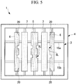
Fig. 5} Fig. 5 is a front view showing a fuel nozzle according to a second embodiment of the present disclosure. - {
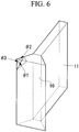
Fig. 6} Fig. 6 is a perspective view showing a tapered portion shown inFig. 5 . - Hereinafter, embodiments according to the present disclosure are described with reference to drawings.
- Hereinafter, a first embodiment of the present disclosure is described with reference to
Figs. 1 to 3 . - A combustion burner of this embodiment combusts a pulverized coal fuel (fuel) obtained by pulverizing mainly coal by a mill, and is provided in a boiler (not shown in the drawing). A plurality of combustion burners are provided for the boiler which includes heat exchange such as a superheater and an evaporator in a flue, and the combustion burners form flames in a furnace.
-
Fig. 1 is a front view of a combustion burner 1. The combustion burner 1 includes: afuel nozzle 3 positioned on the inner side; and a combustionair supply nozzle 4 surrounding thefuel nozzle 3. - The combustion
air supply nozzle 4 forms a flow passage through which only a secondary air passes. Air is supplied through the combustionair supply nozzle 4 such that the air travels in a straight line toward the inside of the furnace. That is, air flowing out from the combustionair supply nozzle 4 is made to flow parallel to a fuel gas flowing out from thefuel nozzle 3 so as not to intersect with the fuel gas flowing out from thefuel nozzle 3. Although not shown in the drawing, a tertiary combustion air nozzle, through which combustion air is supplied, is disposed outside the combustionair supply nozzle 4. - As shown in
Fig. 1 , thefuel nozzle 3 has a rectangular cross section as viewed in a front view, and a fuel gas obtained by mixing pulverized coal and air with each other is made to flow through the inside of thefuel nozzle 3. In the following respective embodiments, the downstream side in a fuel gas flow is simply referred to as "downstream side", and the upstream side in the fuel gas flow is simply referred to as "upstream side". - A plurality of
splitters fuel nozzle 3, and five splitters are disposed in this embodiment. Each of thesplitters fuel nozzle 3 to the side of an upper wall portion (the other wall portion) 3b which is disposed on a side opposite to thelower wall portion 3a. That is, each of thesplitters splitters fuel nozzle 3 bysupport members 8 respectively. - The
fuel nozzle 3 includes a nozzle angle adjusting mechanism which is rotatable in the up-and-down direction together with thesplitters - The
splitters - The splitters include:
slitted splitters non-slitted splitters 7 adjacently disposed on both sides of theslitted splitter 5 disposed in the center. In this way, eachnon-slitted splitter 7 is disposed at a position where thenon-slitted splitter 7 is disposed adjacently to theslitted splitters - As shown in
Fig. 2 , thesplitters portion 10 where a width of the widenedportion 10 is increased as the widenedportion 10 extends in the direction of the fuel gas flow. Further, a plate-shapedportion 11 which extends in the up-and-down direction is disposed on the upstream side of the widenedportion 10 along the direction of the fuel gas flow. - The widened
portions 10 have an approximately triangular shape as shown inFig. 2 as viewed in a cross-sectional view. The widenedportion 10 of theslitted splitter 5 disposed at the center and the widenedportion 10 of thenon-slitted splitter 7 respectively have a shape where a width of the widenedportion 10 is increased toward both sides as shown inFig. 2 as viewed in a cross-sectional view. On the other hand, the widenedportion 10 of theslitted splitter 6 positioned at both ends in the horizontal direction has a shape where a width of the widenedportion 10 is increased toward the center side of thefuel nozzle 3 but is not increased toward the wall portion side of thefuel nozzle 3. In this way, the downstream side of theslitted splitter 6 positioned on both sides is formed into a straight line shape so that a fuel gas which flows between the wall surface of thefuel nozzle 3 and theslitted splitter 6 is prevented from deflecting toward the side of a flow of air flowing out from the combustionair supply nozzle 4. With such a configuration, external ignition which occurs on the outer peripheral side of thefuel nozzle 3 can be suppressed. - As shown in
Fig. 2 ,downstream ends slitted splitters downstream end 3c of thefuel nozzle 3. Downstream ends 7a of thenon-slitted splitters 7 are disposed at a predetermined distance S toward the upstream side from the downstream ends 5a, 6a of theslitted splitters - In this embodiment, assuming an equivalent circle diameter of an opening of the
fuel nozzle 3 as "D", the predetermined distance S is set to 0.001D or more and 1.0D or less, and more preferably set to 0.03D or more and 0.5D or less. It is further preferable to set the predetermined distance S to 0.05D or more and 0.3D or less. - A lower limit value and an upper limit value of the predetermined distance S is determined based on the following viewpoint. When the predetermined distance S becomes lower than the lower limit value, a distance between the
slitted splitters non-slitted splitters 7 becomes extremely small. Accordingly, even when these splitters are displaced from each other so as to ensure a sufficient cross-sectional area of a flow passage, an advantageous effect of such a configuration cannot be obtained. On the other hand, when the predetermined distance S exceeds the upper limit value, a recirculation region formed by thenon-slitted splitters 7 disappears before reaching theslitted splitters non-slitted splitters 7 from theslitted splitters - The predetermined distance S may be adjusted by moving the
non-slitted splitters 7 positioned on the upstream side in the direction of the fuel gas flow as indicated by arrows A inFig. 2 . - As shown in
Fig. 1 , thenon-slitted splitters 7 are formed such that the downstream ends 7a have a fixed width in the direction of the longitudinal axis (an axis in the vertical direction) of thenon-slitted splitters 7. On the other hand, theslitted splitter 5 disposed in the center has a plurality of slits SL each of which partially reduces a width of thedownstream end 5a. Theslitted splitter 5 disposed in the center has the slits SL on both side portions thereof at the same height position. With the formation of these slits, theslitted splitter 5 has wide portions W1 and narrow portions W2. -
Fig. 3 specifically shows a shape of the slits SL. Each slit SL is formed by notching thedownstream end 5a of theslitted splitter 5 in a U shape. Further, an upper surface SL1 and a lower surface SL2 forming the slit SL form surfaces which deflect a fuel gas flow in the direction of the longitudinal axis of the splitter 5 (the up-and-down direction in this embodiment). That is, the upper surface SL1 deflects the fuel gas flow in the downward direction, and the lower surface SL2 deflects the fuel gas flow in the upward direction. - As shown in
Fig. 1 , theslitted splitter 6 disposed at both ends also has slits SL substantially equal to the slits SL formed on theslitted splitter 5 disposed at the center. However, the slits SL are formed only on a side of eachslitted splitter 6 on the center side of thefuel nozzle 3. This is because when the slits SL are formed also on a side of eachslitted splitter 6 on the wall portion side of thefuel nozzle 3, there is a possibility that the slits SL form ignition surfaces to cause external ignition. - It is preferable that the slits SL be formed at a center portion of the
splitters fuel nozzle 3, and that the slits SL be not formed at both upper and lower end portions of thesplitters - Assuming a length of the
splitters - As shown in
Fig. 1 ,flow straightening plates 15 each separating thesesplitters fuel nozzle 3 from each other are formed on upper and lower ends of thesplitters flow straightening plate 15 disposed on the upper side separates a fuel gas flowing on the side of thesplitters upper wall portion 3b of thefuel nozzle 3 from each other. Theflow straightening plate 15 disposed on the lower side separates a fuel gas flowing on the side of thesplitters lower wall portion 3a of thefuel nozzle 3 from each other. - According to the combustion burner 1 having the configuration described above, the following manner of operation and advantageous effects can be acquired.
- With the use of the
slitted splitters fuel nozzle 3 is strengthened. Thenon-slitted splitters 7 form a recirculation region on the downstream of the widenedportion 10 and thus have a flame holding function, but also have a function as a guide member which guides fuel to theslitted splitters non-slitted splitters 7 by making use of the inclined surfaces of the widenedportion 10. Accordingly, internal flame holding by theslitted splitters slitted splitters non-slitted splitters 7 so that reduced combustion is promoted whereby NOx generated in a flame region of the burner can be reduced. - The upper surface SL1 and the lower surface SL2 which are the inclined surfaces forming the slit SL deflect a fuel gas flow in the direction of the longitudinal axis of the
splitters - The
splitters splitters portions 10 of the splitters can be reduced. With such a configuration, an increase in speed of a fuel gas can be suppressed so that a flow speed of a fuel gas toward the downstream side in the direction of the fuel gas flow can be approximated to a combustion speed of a fuel gas toward the upstream side, ignition can be performed at an early stage before the fuel gas further flows toward the downstream side, and hence, flame holding performance of the flame can be enhanced. - The
non-slitted splitters 7 positioned on the upstream side in the fuel gas flow guide a fuel to the recirculation region for theslitted splitters slitted splitters non-slitted splitter 7 as the splitter. - By providing the
flow straightening plates 15, each of which separates the wall surface side of thefuel nozzle 3 and thesplitters splitters - In this embodiment, the
non-slitted splitters 7 are disposed on the upstream side, and theslitted splitters non-slitted splitters 7 and theslitted splitters non-slitted splitters 7 may be disposed on the downstream side, and theslitted splitters slitted splitters slitted splitters - Further, as shown in
Fig. 4 , all splitters may be formed of theslitted splitters slitted splitters - Next, a second embodiment of the present disclosure is described with reference to
Figs. 5 and6 . - This embodiment differs from the first embodiment with respect to a point that tapered portions, where corner portions of the
splitters 6 are removed, are formed on thesplitters 6, and is the same in other respects. Accordingly, components in common are given the same reference numerals, and description thereof is omitted. - As shown in
Fig. 5 , each of theslitted splitters 6 disposed at both ends has a tapered portion (corner-removed portion) 20 at upper and lower corner portions thereof on the center-portion-side of thefuel nozzle 3. - The tapered
portion 20 may have any shape provided that the corner portion is removed. As shown inFig. 6 , it is sufficient for the taperedportion 20 to have a shape where respective vertex angles θ1, θ2, θ3 of three surfaces forming the corner portion are removed. Accordingly, the taperedportion 20 may be formed of a flat surface such as a tapered surface or may be formed of a curved surface. - In this embodiment, unlike in the first embodiment, two
flow straightening plates flow straightening plates fuel nozzle 3 in the height direction, and are formed of plate bodies extending in the horizontal direction. - According to this embodiment, the tapered
portion 20, where the corner portion is removed, is formed so that it is possible to suppress a phenomenon that thesplitter 6 receives radiation from the inner peripheral surface side of thefuel nozzle 3 so that ignition occurs at the corner portion as a starting point whereby external ignition occurs at an outer peripheral portion of thefuel nozzle 3. - The tapered portion (corner-removed portion) 20 may be also formed on other splitters. That is, the tapered
portion 20 may be also formed on theslitted splitter 5 disposed at the center or on thenon-slitted splitters 7. - In the embodiments described above, five splitters are used. However, the present disclosure is not limited to such a configuration. Two to four splitters may be used, or six or more splitters may be used. The optimum number of splitters is designed depending on a size of a fuel nozzle.
- In the respective embodiments described above, the description is made with respect to a case where the
splitters splitters - Further, in the embodiments described above, the description has been made mainly with respect to a case where the fuel is pulverized coal. However, the fuel is not limited to pulverized coal, and the present disclosure is also applicable to a case where the fuel is petroleum coke, a petroleum residue or a biomass fuel (in the form of a solid or slurry).
-
- 1
- combustion burner
- 3
- fuel nozzle
- 4
- combustion air supply nozzle
- 5
- slitted splitter
- 6
- slitted splitter
- 7
- non-slitted splitter
- 10
- widened portion
- 15
- flow straightening plate
- 20
- tapered portion (corner-removed portion)
Claims (7)
- A combustion burner comprising:a fuel nozzle through which a fuel gas obtained by mixing a fuel and air with each other is blown into a furnace; anda plurality of splitters configured to divide a fuel gas flow by a widened portion where a width of the widened portion increases as the widened portion extends in a direction of the fuel gas flow, the splitters being disposed in the fuel nozzle on a distal end side of the fuel nozzle such that longitudinal axes of the splitters extend from a side of one wall portion of the fuel nozzle to a side of the other wall portion which is disposed on a side opposite to said one wall portion,whereinthe plurality of the splitters include: a slitted splitters configured to slit which partially reduces a width of the widened portion at a downstream end in the fuel gas flow, and a non-slitted splitters configured to adjacently to the slitted splitters, the non-slitted splitters having the widened portion, and the widened portion at a downstream end in the fuel gas flow having a fixed width in a direction of the longitudinal axis.
- A combustion burner comprising:a fuel nozzle through which a fuel gas obtained by mixing a fuel and air with each other is blown into a furnace; anda plurality of splitters configured to divide a fuel gas flow by a widened portion where a width of the widened portion increases as the widened portion extends in a direction of the fuel gas flow, the splitters being disposed in the fuel nozzle on a distal end side of the fuel nozzle such that longitudinal axes of the splitters extend from a side of one wall portion of the fuel nozzle to a side of the other wall portion which is disposed on a side opposite to said one wall portion,whereinthe splitter includes a plurality of slitted splitters having a slit which partially reduces a width of the widened portion at a downstream end in the fuel gas flow, andthe slitted splitters disposed adjacently to each other respectively include wide surfaces having no slit, and the wide surfaces of the widened portions of the slitted splitters oppositely face each other.
- The combustion burner according to claim 1 or 2, wherein a surface forming the slit of the slitted splitter is formed of an inclined surface which deflects the fuel gas flow in the direction of the longitudinal axis.
- The combustion burner according to any one of claims 1 to 3, wherein the splitters are disposed at different positions in the direction of the fuel gas flow.
- The combustion burner according to any one of claims 1 to 4, wherein a flow straightening plate configured to separate a wall surface side of the fuel nozzle and the splitter from each other is disposed at an end portion of the splitter in the longitudinal direction.
- The combustion burner according to any one of claims 1 to 5, wherein the splitter has a corner-removed portion, where a corner portion is removed, at a downstream end corner portion of the widened portion.
- A boiler comprising:a furnace;the combustion burner described in any one of claims 1 to 6 which is provided in the furnace;a flue provided on a downstream side of the furnace; anda heat exchanger provided in the flue.
Applications Claiming Priority (2)
| Application Number | Priority Date | Filing Date | Title |
|---|---|---|---|
| JP2015179764A JP6642912B2 (en) | 2015-09-11 | 2015-09-11 | Combustion burner and boiler provided with the same |
| PCT/JP2016/072564 WO2017043218A1 (en) | 2015-09-11 | 2016-08-01 | Combustion burner and boiler provided with same |
Publications (2)
| Publication Number | Publication Date |
|---|---|
| EP3299714A1 true EP3299714A1 (en) | 2018-03-28 |
| EP3299714A4 EP3299714A4 (en) | 2018-07-18 |
Family
ID=58239376
Family Applications (1)
| Application Number | Title | Priority Date | Filing Date |
|---|---|---|---|
| EP16844082.4A Withdrawn EP3299714A4 (en) | 2015-09-11 | 2016-08-01 | Combustion burner and boiler provided with same |
Country Status (9)
| Country | Link |
|---|---|
| US (1) | US10677457B2 (en) |
| EP (1) | EP3299714A4 (en) |
| JP (1) | JP6642912B2 (en) |
| KR (2) | KR20180010246A (en) |
| CN (1) | CN107709881B (en) |
| CL (1) | CL2017003438A1 (en) |
| MX (1) | MX390580B (en) |
| RU (1) | RU2682234C1 (en) |
| WO (1) | WO2017043218A1 (en) |
Cited By (1)
| Publication number | Priority date | Publication date | Assignee | Title |
|---|---|---|---|---|
| CN110017478A (en) * | 2017-12-21 | 2019-07-16 | 三菱日立电力系统株式会社 | The assemble method of burner, the boiler for having the burner and burner |
Families Citing this family (1)
| Publication number | Priority date | Publication date | Assignee | Title |
|---|---|---|---|---|
| JP6926009B2 (en) * | 2018-02-01 | 2021-08-25 | 三菱パワー株式会社 | Combustion burners and boilers |
Family Cites Families (72)
| Publication number | Priority date | Publication date | Assignee | Title |
|---|---|---|---|---|
| US2360548A (en) | 1944-10-17 | Combustion method | ||
| US766494A (en) | 1902-12-17 | 1904-08-02 | Francis G Crone | Gas and air mixing burner. |
| US1103253A (en) | 1910-10-24 | 1914-07-14 | Horatio S Bennett | Burner. |
| US1887330A (en) | 1929-11-15 | 1932-11-08 | William S Shaw | Gas burner |
| US2149980A (en) | 1937-11-04 | 1939-03-07 | Jr Henry Wilbur Paret | Method and apparatus for controlling furnace combustion |
| US2259010A (en) | 1939-05-24 | 1941-10-14 | William F Doyle | Apparatus for combustion of fluid fuel |
| US2895435A (en) | 1954-03-15 | 1959-07-21 | Combustion Eng | Tilting nozzle for fuel burner |
| US3112988A (en) | 1960-02-26 | 1963-12-03 | Sheil Oil Company | Mixing gases at supersonic velocity |
| US3213919A (en) | 1962-05-14 | 1965-10-26 | Calzolari Roberto | Nozzle apparatus for burning fuel |
| US3209811A (en) | 1963-03-28 | 1965-10-05 | Loftus Engineering Corp | Combination high velocity burner |
| US3823875A (en) | 1973-08-24 | 1974-07-16 | T Bauer | Burner nozzle tip for pulverized coal and method for its production |
| US4284402A (en) | 1979-05-02 | 1981-08-18 | Atlantic Richfield Company | Flame modifier to reduce NOx emissions |
| DE8005891U1 (en) | 1980-03-01 | 1981-10-01 | Joh. Vaillant Gmbh U. Co, 5630 Remscheid | PRE-MIXED BURNER OF LOW SWITCHING POWER WITH A GAS-AIR MIXTURE |
| JPS599414A (en) | 1982-07-08 | 1984-01-18 | Babcock Hitachi Kk | Low-nox combustion device |
| WO1984000314A1 (en) | 1982-07-12 | 1984-02-02 | Combustion Eng | Improved nozzle tip for pulverized coal burner |
| JPS5977206A (en) | 1982-10-25 | 1984-05-02 | Babcock Hitachi Kk | Burner device |
| US4634054A (en) * | 1983-04-22 | 1987-01-06 | Combustion Engineering, Inc. | Split nozzle tip for pulverized coal burner |
| IN161339B (en) * | 1983-04-22 | 1987-11-14 | Combustion Eng | |
| JPS60103207A (en) | 1983-11-10 | 1985-06-07 | Mitsubishi Heavy Ind Ltd | Coal burner nozzle |
| JP2791029B2 (en) | 1988-02-23 | 1998-08-27 | バブコツク日立株式会社 | Pulverized coal burner |
| US5292246A (en) | 1988-05-02 | 1994-03-08 | Institut Francais Du Petrole | Burner for the manufacture of synthetic gas comprising a solid element with holes |
| FI98658C (en) | 1990-03-07 | 1997-07-25 | Hitachi Ltd | Burner for pulverized carbon, boiler for pulverized carbon and method for combustion of pulverized carbon |
| JP2954659B2 (en) | 1990-05-21 | 1999-09-27 | バブコツク日立株式会社 | Pulverized coal burner |
| US5215259A (en) | 1991-08-13 | 1993-06-01 | Sure Alloy Steel Corporation | Replaceable insert burner nozzle |
| GB9322016D0 (en) * | 1993-10-26 | 1993-12-15 | Rolls Royce Power Eng | Improvements in or relating to solid fuel burners |
| US5529000A (en) | 1994-08-08 | 1996-06-25 | Combustion Components Associates, Inc. | Pulverized coal and air flow spreader |
| JPH08135919A (en) | 1994-11-11 | 1996-05-31 | Babcock Hitachi Kk | Combustion device |
| DE19539246A1 (en) | 1995-10-21 | 1997-04-24 | Asea Brown Boveri | Airblast atomizer nozzle |
| US6003793A (en) | 1995-12-22 | 1999-12-21 | Mann; Jeffrey S. | Boundary layer coal nozzle assembly for steam generation apparatus |
| JPH09203505A (en) * | 1996-01-29 | 1997-08-05 | Babcock Hitachi Kk | Burner for solid fuel and solid combustion system |
| ES2162680T3 (en) * | 1996-07-08 | 2002-01-01 | Alstom Power Inc | TOWEL TIP FOR SPRAY SOLID FUEL. |
| CN2281479Y (en) | 1996-11-18 | 1998-05-13 | 浙江大学 | Vortex combustion apparatus for wide regulation ratio, varied coals and thin or thick phase coal powers |
| JP3448190B2 (en) | 1997-08-29 | 2003-09-16 | 三菱重工業株式会社 | Gas turbine combustor |
| JPH11281010A (en) | 1998-03-26 | 1999-10-15 | Babcock Hitachi Kk | Solid fuel combustion burner and solid fuel combustion device |
| FR2784449B1 (en) | 1998-10-13 | 2000-12-29 | Stein Heurtey | FLUID FUEL BURNER, PARTICULARLY FOR OVENS FOR HEATING STEEL PRODUCTS |
| FR2790309B1 (en) | 1999-02-25 | 2001-05-11 | Stein Heurtey | IMPROVEMENTS IN OR RELATING TO FLAT BURNERS |
| CN2415254Y (en) | 2000-02-25 | 2001-01-17 | 华中理工大学 | Blunt body burner with fairing plate |
| US6579085B1 (en) | 2000-05-05 | 2003-06-17 | The Boc Group, Inc. | Burner and combustion method for the production of flame jet sheets in industrial furnaces |
| CN1407274A (en) * | 2001-09-05 | 2003-04-02 | 清华同方股份有限公司 | Coal powder direct supplying burner |
| US7163392B2 (en) | 2003-09-05 | 2007-01-16 | Feese James J | Three stage low NOx burner and method |
| US7500849B2 (en) | 2004-01-16 | 2009-03-10 | Air Products And Chemicals, Inc. | Emulsion atomizer nozzle, and burner, and method for oxy-fuel burner applications |
| NO324171B1 (en) | 2006-01-11 | 2007-09-03 | Ntnu Technology Transfer As | Method of combustion of gas, as well as gas burner |
| FR2899313B1 (en) | 2006-03-31 | 2008-05-09 | Huau Christian Bernard Louis | MULTIPURPOSE BURNER WITH HOLLOW FLAME FOR HYDROCARBONS |
| WO2008038426A1 (en) | 2006-09-27 | 2008-04-03 | Babcock-Hitachi Kabushiki Kaisha | Burner, and combustion equipment and boiler comprising burner |
| US20080206696A1 (en) | 2007-02-28 | 2008-08-28 | Wark Rickey E | Tilt nozzle for coal-fired burner |
| EP1985926B1 (en) | 2007-04-26 | 2018-09-05 | Mitsubishi Hitachi Power Systems, Ltd. | Combustion equipment and combustion method |
| JP4922400B2 (en) | 2007-05-30 | 2012-04-25 | 大陽日酸株式会社 | Burner for producing inorganic spheroidized particles |
| CN201228965Y (en) | 2007-08-06 | 2009-04-29 | 国际壳牌研究有限公司 | Combustor |
| DE102007040890A1 (en) | 2007-08-29 | 2009-03-05 | Siemens Ag | Coal dust combination burner with integrated pilot burner |
| US7775791B2 (en) | 2008-02-25 | 2010-08-17 | General Electric Company | Method and apparatus for staged combustion of air and fuel |
| JP5072650B2 (en) * | 2008-02-28 | 2012-11-14 | 三菱重工業株式会社 | Pulverized coal burner |
| US8701572B2 (en) * | 2008-03-07 | 2014-04-22 | Alstom Technology Ltd | Low NOx nozzle tip for a pulverized solid fuel furnace |
| US8104412B2 (en) | 2008-08-21 | 2012-01-31 | Riley Power Inc. | Deflector device for coal piping systems |
| CN201302156Y (en) * | 2008-11-07 | 2009-09-02 | 浙江大学 | External combustion type pulverized coal burner which has the characteristics of tiny-oil ignition and ultra-low load stable combustion |
| JP5535522B2 (en) | 2009-05-22 | 2014-07-02 | 三菱重工業株式会社 | Coal fired boiler |
| JP5374404B2 (en) | 2009-12-22 | 2013-12-25 | 三菱重工業株式会社 | Combustion burner and boiler equipped with this combustion burner |
| DE102010004787B4 (en) | 2010-01-16 | 2014-02-13 | Lurgi Gmbh | Process and burner for the production of synthesis gas |
| JP2012122653A (en) * | 2010-12-07 | 2012-06-28 | Mitsubishi Heavy Ind Ltd | Combustion burner |
| US8915731B2 (en) | 2010-12-30 | 2014-12-23 | L'air Liquide Societe Anonyme Pour L'etude Et L'exploitation Des Procedes Georges Claude | Flameless combustion burner |
| KR20140003558A (en) | 2011-01-21 | 2014-01-09 | 바브콕-히다찌 가부시끼가이샤 | Solid fuel burner and combustion device using same |
| CN102620291B (en) * | 2011-01-31 | 2014-09-24 | 中国科学院过程工程研究所 | Pulverized coal decoupling combustor with low nitrogen oxide discharge and pulverized coal decoupling combustion method with low nitrogen oxide discharge |
| JP5670804B2 (en) * | 2011-04-01 | 2015-02-18 | 三菱重工業株式会社 | Burning burner |
| JP5763389B2 (en) * | 2011-04-01 | 2015-08-12 | 三菱重工業株式会社 | Burning burner |
| JP5778499B2 (en) * | 2011-06-22 | 2015-09-16 | 三菱重工業株式会社 | Solid fuel fired burner and solid fuel fired boiler |
| BR112013024962A2 (en) | 2011-04-01 | 2016-12-20 | Mitsubishi Heavy Ind Ltd | combustion burner, boiler, and method for operating a boiler |
| JP5897363B2 (en) | 2012-03-21 | 2016-03-30 | 川崎重工業株式会社 | Pulverized coal biomass mixed burner |
| CN202938290U (en) | 2012-11-05 | 2013-05-15 | 徐州燃控科技股份有限公司 | Internal combustion and multi-channel low-nitrogen combustor |
| CN104100969B (en) | 2013-04-12 | 2017-04-12 | 气体产品与化学公司 | Wide-flame, Oxy-solid Fuel Burner |
| CN103267282B (en) | 2013-06-11 | 2016-05-11 | 牛博申 | Deep or light separation coal burner |
| CN103672883B (en) | 2013-12-21 | 2017-02-22 | 哈尔滨锅炉厂有限责任公司 | Grid type swirl burner |
| CN203718765U (en) | 2014-02-10 | 2014-07-16 | 四川川锅锅炉有限责任公司 | Low-NOx burner with tertiary air |
| JP5901737B2 (en) * | 2014-12-18 | 2016-04-13 | 三菱重工業株式会社 | Burning burner |
-
2015
- 2015-09-11 JP JP2015179764A patent/JP6642912B2/en active Active
-
2016
- 2016-08-01 KR KR1020177036865A patent/KR20180010246A/en not_active Ceased
- 2016-08-01 CN CN201680037949.6A patent/CN107709881B/en active Active
- 2016-08-01 US US15/736,108 patent/US10677457B2/en active Active
- 2016-08-01 MX MX2017016352A patent/MX390580B/en unknown
- 2016-08-01 WO PCT/JP2016/072564 patent/WO2017043218A1/en not_active Ceased
- 2016-08-01 RU RU2017145603A patent/RU2682234C1/en active
- 2016-08-01 KR KR1020197026894A patent/KR102297896B1/en active Active
- 2016-08-01 EP EP16844082.4A patent/EP3299714A4/en not_active Withdrawn
-
2017
- 2017-12-28 CL CL2017003438A patent/CL2017003438A1/en unknown
Cited By (1)
| Publication number | Priority date | Publication date | Assignee | Title |
|---|---|---|---|---|
| CN110017478A (en) * | 2017-12-21 | 2019-07-16 | 三菱日立电力系统株式会社 | The assemble method of burner, the boiler for having the burner and burner |
Also Published As
| Publication number | Publication date |
|---|---|
| CN107709881A (en) | 2018-02-16 |
| MX2017016352A (en) | 2018-05-02 |
| WO2017043218A1 (en) | 2017-03-16 |
| MX390580B (en) | 2025-03-20 |
| RU2682234C1 (en) | 2019-03-15 |
| US20180195715A1 (en) | 2018-07-12 |
| KR20180010246A (en) | 2018-01-30 |
| JP2017053601A (en) | 2017-03-16 |
| US10677457B2 (en) | 2020-06-09 |
| EP3299714A4 (en) | 2018-07-18 |
| CN107709881B (en) | 2021-12-28 |
| KR20190108651A (en) | 2019-09-24 |
| KR102297896B1 (en) | 2021-09-03 |
| CL2017003438A1 (en) | 2018-04-20 |
| JP6642912B2 (en) | 2020-02-12 |
Similar Documents
| Publication | Publication Date | Title |
|---|---|---|
| EP2518404B1 (en) | Combustion burner and boiler provided with such burner | |
| AU2007301377B2 (en) | Burner, and combustion equipment and boiler comprising burner | |
| CN104508372B (en) | Solid fuel burner | |
| ES2821325T3 (en) | Combustion burner and boiler | |
| US9702545B2 (en) | Oil-fired burner, solid fuel-fired burner unit, and solid fuel-fired boiler | |
| US10677457B2 (en) | Combustion burner and boiler equipped with the same | |
| JP6632841B2 (en) | Combustion burner and boiler provided with the same | |
| EP3279563B1 (en) | Combustion burner and boiler provided therewith | |
| JP6640592B2 (en) | Combustion burner, combustion device and boiler | |
| JP6640591B2 (en) | Combustion burner, combustion device and boiler | |
| JP7046579B2 (en) | Combustion burner and boiler equipped with it | |
| JP7492420B2 (en) | Combustion burners and boilers | |
| CN111602005B (en) | Burners and burners and boilers | |
| JP2010139181A (en) | Swirl combustion boiler | |
| CN110300871A (en) | Burner |
Legal Events
| Date | Code | Title | Description |
|---|---|---|---|
| PUAI | Public reference made under article 153(3) epc to a published international application that has entered the european phase |
Free format text: ORIGINAL CODE: 0009012 |
|
| 17P | Request for examination filed |
Effective date: 20171221 |
|
| AK | Designated contracting states |
Kind code of ref document: A1 Designated state(s): AL AT BE BG CH CY CZ DE DK EE ES FI FR GB GR HR HU IE IS IT LI LT LU LV MC MK MT NL NO PL PT RO RS SE SI SK SM TR |
|
| AX | Request for extension of the european patent |
Extension state: BA ME |
|
| A4 | Supplementary search report drawn up and despatched |
Effective date: 20180620 |
|
| RIC1 | Information provided on ipc code assigned before grant |
Ipc: F23D 1/00 20060101AFI20180612BHEP |
|
| DAV | Request for validation of the european patent (deleted) | ||
| DAX | Request for extension of the european patent (deleted) | ||
| 17Q | First examination report despatched |
Effective date: 20190320 |
|
| GRAP | Despatch of communication of intention to grant a patent |
Free format text: ORIGINAL CODE: EPIDOSNIGR1 |
|
| INTG | Intention to grant announced |
Effective date: 20191120 |
|
| STAA | Information on the status of an ep patent application or granted ep patent |
Free format text: STATUS: THE APPLICATION IS DEEMED TO BE WITHDRAWN |
|
| 18D | Application deemed to be withdrawn |
Effective date: 20200603 |