EP3299683A1 - Sealing device - Google Patents
Sealing device Download PDFInfo
- Publication number
- EP3299683A1 EP3299683A1 EP16799881.4A EP16799881A EP3299683A1 EP 3299683 A1 EP3299683 A1 EP 3299683A1 EP 16799881 A EP16799881 A EP 16799881A EP 3299683 A1 EP3299683 A1 EP 3299683A1
- Authority
- EP
- European Patent Office
- Prior art keywords
- grease
- lip
- face
- peripheral surface
- inner peripheral
- Prior art date
- Legal status (The legal status is an assumption and is not a legal conclusion. Google has not performed a legal analysis and makes no representation as to the accuracy of the status listed.)
- Withdrawn
Links
- 238000007789 sealing Methods 0.000 title claims abstract description 71
- 239000004519 grease Substances 0.000 claims abstract description 154
- 230000002093 peripheral effect Effects 0.000 claims description 137
- 239000000463 material Substances 0.000 claims description 19
- 238000005461 lubrication Methods 0.000 claims description 4
- 230000001050 lubricating effect Effects 0.000 abstract description 2
- 239000011248 coating agent Substances 0.000 abstract 3
- 238000000576 coating method Methods 0.000 abstract 3
- 239000002184 metal Substances 0.000 description 15
- XLYOFNOQVPJJNP-UHFFFAOYSA-N water Substances O XLYOFNOQVPJJNP-UHFFFAOYSA-N 0.000 description 10
- 230000002708 enhancing effect Effects 0.000 description 6
- 230000000694 effects Effects 0.000 description 5
- 238000004132 cross linking Methods 0.000 description 4
- 230000003247 decreasing effect Effects 0.000 description 3
- 239000012530 fluid Substances 0.000 description 3
- 239000000725 suspension Substances 0.000 description 3
- 238000009826 distribution Methods 0.000 description 2
- 238000002360 preparation method Methods 0.000 description 2
- 239000013013 elastic material Substances 0.000 description 1
- 239000006247 magnetic powder Substances 0.000 description 1
- 238000000034 method Methods 0.000 description 1
- 239000011295 pitch Substances 0.000 description 1
Images





Classifications
-
- F—MECHANICAL ENGINEERING; LIGHTING; HEATING; WEAPONS; BLASTING
- F16—ENGINEERING ELEMENTS AND UNITS; GENERAL MEASURES FOR PRODUCING AND MAINTAINING EFFECTIVE FUNCTIONING OF MACHINES OR INSTALLATIONS; THERMAL INSULATION IN GENERAL
- F16J—PISTONS; CYLINDERS; SEALINGS
- F16J15/00—Sealings
- F16J15/16—Sealings between relatively-moving surfaces
- F16J15/32—Sealings between relatively-moving surfaces with elastic sealings, e.g. O-rings
- F16J15/3204—Sealings between relatively-moving surfaces with elastic sealings, e.g. O-rings with at least one lip
- F16J15/3232—Sealings between relatively-moving surfaces with elastic sealings, e.g. O-rings with at least one lip having two or more lips
-
- F—MECHANICAL ENGINEERING; LIGHTING; HEATING; WEAPONS; BLASTING
- F16—ENGINEERING ELEMENTS AND UNITS; GENERAL MEASURES FOR PRODUCING AND MAINTAINING EFFECTIVE FUNCTIONING OF MACHINES OR INSTALLATIONS; THERMAL INSULATION IN GENERAL
- F16C—SHAFTS; FLEXIBLE SHAFTS; ELEMENTS OR CRANKSHAFT MECHANISMS; ROTARY BODIES OTHER THAN GEARING ELEMENTS; BEARINGS
- F16C33/00—Parts of bearings; Special methods for making bearings or parts thereof
- F16C33/72—Sealings
- F16C33/76—Sealings of ball or roller bearings
- F16C33/78—Sealings of ball or roller bearings with a diaphragm, disc, or ring, with or without resilient members
-
- F—MECHANICAL ENGINEERING; LIGHTING; HEATING; WEAPONS; BLASTING
- F16—ENGINEERING ELEMENTS AND UNITS; GENERAL MEASURES FOR PRODUCING AND MAINTAINING EFFECTIVE FUNCTIONING OF MACHINES OR INSTALLATIONS; THERMAL INSULATION IN GENERAL
- F16C—SHAFTS; FLEXIBLE SHAFTS; ELEMENTS OR CRANKSHAFT MECHANISMS; ROTARY BODIES OTHER THAN GEARING ELEMENTS; BEARINGS
- F16C33/00—Parts of bearings; Special methods for making bearings or parts thereof
- F16C33/72—Sealings
- F16C33/76—Sealings of ball or roller bearings
- F16C33/78—Sealings of ball or roller bearings with a diaphragm, disc, or ring, with or without resilient members
- F16C33/7816—Details of the sealing or parts thereof, e.g. geometry, material
- F16C33/782—Details of the sealing or parts thereof, e.g. geometry, material of the sealing region
-
- F—MECHANICAL ENGINEERING; LIGHTING; HEATING; WEAPONS; BLASTING
- F16—ENGINEERING ELEMENTS AND UNITS; GENERAL MEASURES FOR PRODUCING AND MAINTAINING EFFECTIVE FUNCTIONING OF MACHINES OR INSTALLATIONS; THERMAL INSULATION IN GENERAL
- F16C—SHAFTS; FLEXIBLE SHAFTS; ELEMENTS OR CRANKSHAFT MECHANISMS; ROTARY BODIES OTHER THAN GEARING ELEMENTS; BEARINGS
- F16C33/00—Parts of bearings; Special methods for making bearings or parts thereof
- F16C33/72—Sealings
- F16C33/76—Sealings of ball or roller bearings
- F16C33/78—Sealings of ball or roller bearings with a diaphragm, disc, or ring, with or without resilient members
- F16C33/7869—Sealings of ball or roller bearings with a diaphragm, disc, or ring, with or without resilient members mounted with a cylindrical portion to the inner surface of the outer race and having a radial portion extending inward
- F16C33/7873—Sealings of ball or roller bearings with a diaphragm, disc, or ring, with or without resilient members mounted with a cylindrical portion to the inner surface of the outer race and having a radial portion extending inward with a single sealing ring of generally L-shaped cross-section
- F16C33/7876—Sealings of ball or roller bearings with a diaphragm, disc, or ring, with or without resilient members mounted with a cylindrical portion to the inner surface of the outer race and having a radial portion extending inward with a single sealing ring of generally L-shaped cross-section with sealing lips
-
- F—MECHANICAL ENGINEERING; LIGHTING; HEATING; WEAPONS; BLASTING
- F16—ENGINEERING ELEMENTS AND UNITS; GENERAL MEASURES FOR PRODUCING AND MAINTAINING EFFECTIVE FUNCTIONING OF MACHINES OR INSTALLATIONS; THERMAL INSULATION IN GENERAL
- F16C—SHAFTS; FLEXIBLE SHAFTS; ELEMENTS OR CRANKSHAFT MECHANISMS; ROTARY BODIES OTHER THAN GEARING ELEMENTS; BEARINGS
- F16C33/00—Parts of bearings; Special methods for making bearings or parts thereof
- F16C33/72—Sealings
- F16C33/76—Sealings of ball or roller bearings
- F16C33/78—Sealings of ball or roller bearings with a diaphragm, disc, or ring, with or without resilient members
- F16C33/7869—Sealings of ball or roller bearings with a diaphragm, disc, or ring, with or without resilient members mounted with a cylindrical portion to the inner surface of the outer race and having a radial portion extending inward
- F16C33/7879—Sealings of ball or roller bearings with a diaphragm, disc, or ring, with or without resilient members mounted with a cylindrical portion to the inner surface of the outer race and having a radial portion extending inward with a further sealing ring
- F16C33/7883—Sealings of ball or roller bearings with a diaphragm, disc, or ring, with or without resilient members mounted with a cylindrical portion to the inner surface of the outer race and having a radial portion extending inward with a further sealing ring mounted to the inner race and of generally L-shape, the two sealing rings defining a sealing with box-shaped cross-section
-
- F—MECHANICAL ENGINEERING; LIGHTING; HEATING; WEAPONS; BLASTING
- F16—ENGINEERING ELEMENTS AND UNITS; GENERAL MEASURES FOR PRODUCING AND MAINTAINING EFFECTIVE FUNCTIONING OF MACHINES OR INSTALLATIONS; THERMAL INSULATION IN GENERAL
- F16J—PISTONS; CYLINDERS; SEALINGS
- F16J15/00—Sealings
- F16J15/16—Sealings between relatively-moving surfaces
- F16J15/32—Sealings between relatively-moving surfaces with elastic sealings, e.g. O-rings
- F16J15/324—Arrangements for lubrication or cooling of the sealing itself
-
- F—MECHANICAL ENGINEERING; LIGHTING; HEATING; WEAPONS; BLASTING
- F16—ENGINEERING ELEMENTS AND UNITS; GENERAL MEASURES FOR PRODUCING AND MAINTAINING EFFECTIVE FUNCTIONING OF MACHINES OR INSTALLATIONS; THERMAL INSULATION IN GENERAL
- F16C—SHAFTS; FLEXIBLE SHAFTS; ELEMENTS OR CRANKSHAFT MECHANISMS; ROTARY BODIES OTHER THAN GEARING ELEMENTS; BEARINGS
- F16C19/00—Bearings with rolling contact, for exclusively rotary movement
- F16C19/02—Bearings with rolling contact, for exclusively rotary movement with bearing balls essentially of the same size in one or more circular rows
- F16C19/14—Bearings with rolling contact, for exclusively rotary movement with bearing balls essentially of the same size in one or more circular rows for both radial and axial load
- F16C19/18—Bearings with rolling contact, for exclusively rotary movement with bearing balls essentially of the same size in one or more circular rows for both radial and axial load with two or more rows of balls
- F16C19/181—Bearings with rolling contact, for exclusively rotary movement with bearing balls essentially of the same size in one or more circular rows for both radial and axial load with two or more rows of balls with angular contact
- F16C19/183—Bearings with rolling contact, for exclusively rotary movement with bearing balls essentially of the same size in one or more circular rows for both radial and axial load with two or more rows of balls with angular contact with two rows at opposite angles
- F16C19/184—Bearings with rolling contact, for exclusively rotary movement with bearing balls essentially of the same size in one or more circular rows for both radial and axial load with two or more rows of balls with angular contact with two rows at opposite angles in O-arrangement
-
- F—MECHANICAL ENGINEERING; LIGHTING; HEATING; WEAPONS; BLASTING
- F16—ENGINEERING ELEMENTS AND UNITS; GENERAL MEASURES FOR PRODUCING AND MAINTAINING EFFECTIVE FUNCTIONING OF MACHINES OR INSTALLATIONS; THERMAL INSULATION IN GENERAL
- F16C—SHAFTS; FLEXIBLE SHAFTS; ELEMENTS OR CRANKSHAFT MECHANISMS; ROTARY BODIES OTHER THAN GEARING ELEMENTS; BEARINGS
- F16C2326/00—Articles relating to transporting
- F16C2326/01—Parts of vehicles in general
- F16C2326/02—Wheel hubs or castors
-
- F—MECHANICAL ENGINEERING; LIGHTING; HEATING; WEAPONS; BLASTING
- F16—ENGINEERING ELEMENTS AND UNITS; GENERAL MEASURES FOR PRODUCING AND MAINTAINING EFFECTIVE FUNCTIONING OF MACHINES OR INSTALLATIONS; THERMAL INSULATION IN GENERAL
- F16C—SHAFTS; FLEXIBLE SHAFTS; ELEMENTS OR CRANKSHAFT MECHANISMS; ROTARY BODIES OTHER THAN GEARING ELEMENTS; BEARINGS
- F16C33/00—Parts of bearings; Special methods for making bearings or parts thereof
- F16C33/30—Parts of ball or roller bearings
- F16C33/66—Special parts or details in view of lubrication
- F16C33/6603—Special parts or details in view of lubrication with grease as lubricant
- F16C33/6607—Retaining the grease in or near the bearing
-
- F—MECHANICAL ENGINEERING; LIGHTING; HEATING; WEAPONS; BLASTING
- F16—ENGINEERING ELEMENTS AND UNITS; GENERAL MEASURES FOR PRODUCING AND MAINTAINING EFFECTIVE FUNCTIONING OF MACHINES OR INSTALLATIONS; THERMAL INSULATION IN GENERAL
- F16C—SHAFTS; FLEXIBLE SHAFTS; ELEMENTS OR CRANKSHAFT MECHANISMS; ROTARY BODIES OTHER THAN GEARING ELEMENTS; BEARINGS
- F16C33/00—Parts of bearings; Special methods for making bearings or parts thereof
- F16C33/72—Sealings
- F16C33/76—Sealings of ball or roller bearings
- F16C33/80—Labyrinth sealings
- F16C33/805—Labyrinth sealings in addition to other sealings, e.g. dirt guards to protect sealings with sealing lips
-
- F—MECHANICAL ENGINEERING; LIGHTING; HEATING; WEAPONS; BLASTING
- F16—ENGINEERING ELEMENTS AND UNITS; GENERAL MEASURES FOR PRODUCING AND MAINTAINING EFFECTIVE FUNCTIONING OF MACHINES OR INSTALLATIONS; THERMAL INSULATION IN GENERAL
- F16C—SHAFTS; FLEXIBLE SHAFTS; ELEMENTS OR CRANKSHAFT MECHANISMS; ROTARY BODIES OTHER THAN GEARING ELEMENTS; BEARINGS
- F16C41/00—Other accessories, e.g. devices integrated in the bearing not relating to the bearing function as such
- F16C41/007—Encoders, e.g. parts with a plurality of alternating magnetic poles
Definitions
- the present invention relates to a sealing device according to a sealing technique.
- the sealing device according to the present invention is used, for example, as a hub bearing seal for a vehicle such as a motor vehicle, or is used as the other bearing seals.
- a sealing device 51 shown in Fig. 6 has been conventionally known as a sealing device which is used in a hub bearing portion in a vehicle such as a motor vehicle.
- the sealing device 51 mainly fulfills a function of sealing a foreign material (muddy water, not shown) in a bearing outer portion O so as to prevent the foreign material from entering into a bearing inner portion I, and is accordingly provided with an end face lip 52 which slidably comes into contact with an end face portion 33 of a bearing rotation side part (refer to patent document 1).
- Patent Document 1 Japanese Unexamined Patent Publication No. 2009-180366
- the grease G is applied to an inner peripheral surface of a leading end portion 52b in the end face lip 52 at a comparatively large amount, and is applied to an inner peripheral surface of a root portion 52a in the end face lip 52 at a comparatively small amount as shown. More specifically, since an application thickness t1 of the grease G applied to the inner peripheral surface of the lip leading end portion 52b in the end face lip 52 is set to be thicker (larger) than an application thickness t2 of the grease G applied to the inner peripheral surface of the lip root portion 52a (t1 > t2), the applied grease G has a great contact width w1 at which the grease comes into contact with the end face portion 33 of the rotation side part.
- the present invention is made by taking the above points into consideration, and an object of the present invention is to provide a sealing device structured such that a grease applied to an inner peripheral surface of an end face lip is hard to be scattered even in the case that a centrifugal force acts on the sealing device.
- the present invention employs the following means.
- a sealing device is a sealing device sealing a foreign material in a machine outer side so as to prevent the foreign material from entering into a machine inner side, having an end face lip which slidably comes into contact with an end face portion of a rotation side part, and applying grease for lubrication to an inner peripheral surface of the end face lip, wherein an application amount of the grease applied to an inner peripheral surface of a leading end portion in the end face lip is set to be smaller than an application amount of the grease applied to an inner peripheral surface of a root portion in the end face lip (claim 1).
- the application amount of the grease applied to the inner peripheral surface of the leading end portion in the end face lip is set to be smaller than the application amount of the grease applied to the inner peripheral surface of the root portion in the end face lip, a contact width of the applied grease coming into contact with the end face portion of the rotation side part becomes smaller in comparison with the conventional one. Accordingly, the applied grease is hard to be affected by the centrifugal force. As a result, it is possible to inhibit the grease from passing through the sliding portion of the end face lip and being scattered.
- the grease is applied over a whole peripheral of the inner peripheral surface in the end face lip, and an application thickness of the grease applied to the inner peripheral surface of the leading end portion in the end face is set to be smaller than an application thickness of the grease applied to the inner peripheral surface of the root portion in the end face lip on the assumption thereof (claim 2).
- the grease is applied to a part of a circumference of the inner peripheral surface of the end face lip, and any one or both of an application thickness and an application width in a circumferential direction of the grease applied to the inner peripheral surface of the leading end portion in the end face lip is set to be smaller than an application thickness or an application width in a circumferential direction of the grease applied to the inner peripheral surface of the root portion in the end face lip on the assumption thereof (claim 3).
- grease trap is provided in an outer peripheral side of the end face lip in preparation for the case that the grease passes through the sliding portion of the end face lip. Since the grease trap collects the grease in the case that the grease trap is provided in the outer peripheral side of the end face lip as mentioned above, it is possible to inhibit the grease from being scattered (claim 4).
- the sealing device Since the sealing device according to the present invention exerts an effect of preventing the grease from being scattered, the sealing device is suitably used as a hub bearing seal for a vehicle such as a motor vehicle and the other bearing seals which are provided with a structure applying the grease to an inner peripheral surface of an end face lip (claim 5).
- the sealing device structured such that the grease applied to the inner peripheral surface of the end face lip is hard to be scattered even in the case that the centrifugal force acts on the sealing device.
- Fig. 1 shows a cross section of a substantial part of a sealing device 1 according to a first embodiment of the present invention.
- the sealing device 1 according to the embodiment is used as a hub bearing seal (a hub seal) in a bearing portion in a wheel suspension device for a motor vehicle, and is structured as follows.
- the sealing device is provided with a mounting ring 11 which is fixed to an inner peripheral surface of a housing 31 such as a bearing outer ring corresponding to a stationary side mounting part in the bearing portion and is made of a rigid material such as a metal, and a rubber-like elastic body 21 made of a predetermined rubber material is attached (crosslinking bonded) to the mounting ring 11.
- the mounting ring 11 has a tubular portion 12 which is fitted and attached to an inner peripheral surface of the housing 31, and a radially inward flange portion 14 is integrally formed in an end portion in one side (a right side in the drawing) in an axial direction of the tubular portion 12 via a bent portion 13.
- the rubber-like elastic body 21 is attached to the bent portion 13 and the flange portion 14 in the mounting ring 11, and an outer peripheral seal portion 22, an end face lip (a side lip) 23, a second end face lip (a second side lip) 24 and a radial lip (a grease lip) 25 are integrally formed by the rubber-like elastic body 21.
- the outer peripheral seal portion 22 comes into contact with an inner peripheral surface of the housing 31 in a stationary manner.
- the end face lip 23 slidably comes into contact with an end face portion (an end face portion in an axial direction) 33 of a shaft 32 such as a bearing inner ring corresponding to a rotation side part in the bearing portion.
- the second end face lip 24 slidably comes into contact with the end face portion 33 of the shaft 32 in the same manner in an inner peripheral side of the end face lip 23.
- the radial lip 25 slidably comes into contact with an outer peripheral surface portion 34 of the shaft 32 in a bearing inner portion (a machine inner side) I side of the second end face lip 24.
- a round portion having a circular arc cross sectional shape is included in the end face portion 33 as shown in the drawing.
- the end face lip 23 and the second end face lip 24 are respectively formed so that diameters thereof are enlarged little by little from lip root portions 23a and 24a toward lip leading end portions 23b and 24b, are provided with the lip leading end portions 23b and 24b so as to be directed to an outer peripheral side, and mainly exert a sealing function so as to prevent a foreign material such as muddy water in a bearing outer portion (a machine outer side) O from entering into the machine inner side I on the basis of the lip leading end portions 23b and 24b slidably coming into contact with the end face portion 33 of the shaft 32.
- Grease G constructed by fluid having viscosity is applied to each of the inner peripheral surfaces of the lips 23, 24 and 25, for enhancing a muddy water resistance of the lips 23, 24 and 25 and further enhancing a sliding resistance thereof.
- the grease G applied to the inner peripheral surface of the end face lip 23 is set to be applied to an inner peripheral surface of a leading end portion 23b in the end face lip 23 at a comparatively small amount and be applied to an inner peripheral surface of a root portion 23a in the end face lip 23 at a comparatively large amount. More specifically, the grease G is applied over a whole periphery of the inner peripheral surface of the end face lip 23, and an application thickness t1 of the grease G applied to the inner peripheral surface of the leading end portion 23b in the end face lip 23 is set to be smaller than an application thickness t2 of the grease G applied to the inner peripheral surface of the root portion 23a in the end face lip 23 (t1 ⁇ t2). Further, the application thickness of the grease G is set to be enlarged little by little from the lip leading end portion 23b toward the lip root portion 23a, and is on the contrary set to become smaller little by little from the lip root portion 23a toward the lip leading end portion 23b.
- the grease G is set to be applied to the inner peripheral surface of the leading end portion 23b in the end face lip 23 at the comparatively small amount and be applied to the inner peripheral surface of the root portion 23a in the end face lip 23 at the comparatively large amount, and the application thickness t1 of the grease G applied to the inner peripheral surface of the leading end portion 23b in the end face lip 23 is set to be smaller than the application thickness t2 of the grease G applied to the inner peripheral surface of the root portion 23a in the end face lip 23.
- a contact width w2 of the applied grease with the end face portion 33 of the shaft 32 is set to be much smaller in comparison with a contact width w1 in the prior art shown in Fig. 7 mentioned above (w1 > w2).
- the centrifugal force is generated in conjunction with the rotation of the shaft 32 under the structure mentioned above, the centrifugal force is hard to affect the grease G.
- the present invention is characterized in that the application amount of the grease G applied to the inner peripheral surface of the lip leading end portion 23b in the end face lip 23 is set to be smaller than the application amount of the grease G applied to the inner peripheral surface of the root portion 23a in the end face lip 23.
- the grease G is applied over the whole periphery of the inner peripheral surface in the end face lip 23, and the application thickness t1 of the grease G applied to the inner peripheral surface of the leading end portion 23b in the end face lip 23 is set to be smaller than the application thickness t2 of the grease G applied to the inner peripheral surface of the root portion 23a in the end face lip 23 (t1 ⁇ t2).
- the grease G may be applied to a part of a circumference of the inner peripheral surface of the end face lip 23. A description will be given below of an example in this case.
- the grease G is applied to a plurality of positions in a part of the circumference of the inner peripheral surface of the end face lip 23, and an application width c1 in a circumferential direction of the grease G applied to the inner peripheral surface of the leading end portion 23b in the end face lip 23 is set to be smaller than an application width c2 in a circumferential direction of the grease G applied to the inner peripheral surface of the root portion 23a in the end face lip 23 (c1 ⁇ c2).
- the application thickness t of the grease is set to be fixed or approximately fixed.
- the grease G is applied to a plurality of positions in a part of the circumference of the inner peripheral surface of the end face lip 23, and the application width c1 in the circumferential direction of the grease G applied to the inner peripheral surface of the leading end portion 23b in the end face lip 23 is set to be smaller than the application width c2 in the circumferential direction of the grease G applied to the inner peripheral surface of the root portion 23a in the end face lip 23 (c1 ⁇ c2).
- the application thickness t1 of the grease G applied to the inner peripheral surface of the leading end portion 23b in the end face lip 23 is set to be smaller than the application thickness t2 of the grease G applied to the inner peripheral surface of the root portion 23a in the end face lip 23 (t1 ⁇ t2).
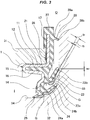
- Fig. 3 shows a cross section of a substantial part of a sealing device 1 according to a second embodiment of the present invention.
- the sealing device 1 according to the embodiment is used as a hub bearing seal (a hub seal) in a bearing portion in a wheel suspension device for a motor vehicle, and is structured as follows.
- the sealing device is provided with a mounting ring 11 which is fixed to an inner peripheral surface of a housing 31 such as a bearing outer ring corresponding to a stationary side mounting part in the bearing portion and is made of a rigid material such as a metal, and a rubber-like elastic body 21 made of a predetermined rubber material is attached (crosslinking bonded) to the mounting ring 11.
- the mounting ring 11 has a tubular portion 12 which is fitted and attached to an inner peripheral surface of the housing 31, and a radially inward flange portion 14 is integrally formed in an end portion in one side (a left side in the drawing) in an axial direction of the tubular portion 12 via a bent portion 15 and an inner peripheral tube portion 16. Further, a radially outward flange portion 17 is integrally formed in an end portion in the other side (a right side in the drawing) in the axial direction of the tubular portion 12.
- the rubber-like elastic body 21 is attached to the tubular portion 12, the bent portion 15, the inner peripheral portion 16 and both the flange portions 14 and 17 in the mounting ring 11, and an end face seal portion 26, an outer peripheral cover portion 27, an end face lip (a side lip) 23, a second end face lip (a second side lip) 24 and a radial lip (a grease lip) 25 are integrally formed by the rubber-like elastic body 21.
- the end face seal portion 26 comes into contact with an end face portion of the housing 31 in a stationary manner.
- the outer peripheral cover portion 27 covers the outward flange portion 17 of the mounting ring 11.
- the end face lip 23 slidably comes into contact with an end face portion (an end face portion in an axial direction) 33 of a shaft 32 such as a bearing inner ring corresponding to a rotation side part in the bearing portion.
- the second end face lip 24 slidably comes into contact with the end face portion 33 of the shaft 32 in the same manner in an inner peripheral side of the end face lip 23.
- the radial lip 25 slidably comes into contact with an outer peripheral surface portion 34 of the shaft 32 in a bearing inner portion (a machine inner side) I side of the second end face lip 24.
- a round portion having a circular arc cross sectional shape is included in the end face portion 33 as shown in the drawing.
- the end face lip 23 and the second end face lip 24 are respectively formed so that diameters thereof are enlarged little by little from the lip root portions 23a and 24a toward the lip leading end portions 23b and 24b, are provided with the lip leading end portions 23b and 24b so as to be directed to an outer peripheral side, and mainly exert a sealing function so as to prevent a foreign material such as muddy water in a bearing outer portion (a machine outer side) O from entering into the machine inner side I on the basis of the lip leading end portions 23b and 24b slidably coming into contact with the end face portion 33 of the shaft 32.
- Grease G constructed by fluid having a viscosity is applied to each of inner peripheral surfaces of the lips 23, 24 and 25, for enhancing a muddy water resistance of the lips 23, 24 and 25 and further enhancing a sliding resistance thereof.
- the grease G applied to the inner peripheral surface of the end face lip 23 is set to be applied to an inner peripheral surface of a leading end portion 23b in the end face lip 23 at a comparatively small amount and be applied to an inner peripheral surface of a root portion 23a in the end face lip 23 at a comparatively large amount. More specifically, the grease G is applied over a whole periphery of the inner peripheral surface of the end face lip 23, and an application thickness t1 of the grease G applied to the inner peripheral surface of the leading end portion 23b in the end face lip 23 is set to be smaller than an application thickness t2 of the grease G applied to the inner peripheral surface of the root portion 23a in the end face lip 23 (t1 ⁇ t2). Further, the application thickness of the grease G is set to be enlarged little by little from the lip leading end portion 23b toward the lip root portion 23a, and is on the contrary set to become smaller little by little from the lip root portion 23a toward the lip leading end portion 23b.
- grease trap 28 is provided so as to be positioned in an outer peripheral side of the end face lip 23.
- the grease trap 28 is formed into an annular shape and a lip shape, and is formed into such a shape that an inner diameter thereof is decreased little by little from a trap root portion 28a toward a trap leading end portion 28b of the grease trap 28. Further, the grease trap 28 is integrally formed with the outer peripheral cover portion 27 by the rubber-like elastic body 21, and slidably comes into contact with the end face portion 33 of the shaft 32 with the leading end portion 28b thereof.
- the grease G is set to be applied to the inner peripheral surface of the leading end portion 23b in the end face lip 23 at the comparatively small amount and be applied to the inner peripheral surface of the root portion 23a in the end face lip 23 at the comparatively large amount, and the application thickness t1 of the grease G applied to the inner peripheral surface of the leading end portion 23b in the end face lip 23 is set to be smaller than the application thickness t2 of the grease G applied to the inner peripheral surface of the root portion 23a in the end face lip 23.
- a contact width w2 of the applied grease with the end face portion 33 of the shaft 32 is set to be much smaller in comparison with a contact width w1 in the prior art shown in Fig. 7 mentioned above (w1 > w2).
- the centrifugal force is generated in conjunction with the rotation of the shaft 32 under the structure mentioned above, the centrifugal force is hard to affect the grease G.
- the grease trap 28 is previously provided in the outer peripheral side of the end face lip 23 in preparation for the case that the grease G passes through the sliding portion of the end face lip 23, the grease trap 28 can collect the grease G. Therefore, it is possible to inhibit the grease G from being scattered toward the outer peripheral side from the sealing device 1.
- the grease trap 28 is formed into the annular shape and the lip shape, and is formed into such the shape that the inner diameter is decreased little by little from the trap root portion 28a toward the trap leading end portion 28b of the grease trap 28. Therefore, the collected grease G flows along an inner peripheral surface of the grease trap 28 from the trap leading end portion 28b side toward the trap root portion 28a side and is hard to flow out of the trap leading end portion 28b. As a result, an effect of collecting the grease is high.
- the end face lip 23 is structured such that the end face lip 23 slidably comes into contact with the end face portion (the end portion in the axial direction) 33 of the flange portion which is provided in the shaft 32 such as the bearing inner ring corresponding to the other end of sliding, however, the other end of sliding may be set to the other part than the flange portion provided in the shaft 32, for example, may be set to a metal ring which is mounted to an outer peripheral surface of the shaft 32. A description will be given below of an example in this case.
- Fig. 4 shows a cross section of a substantial part of a sealing device 1 according to a third embodiment of the present invention.
- the sealing device 1 according to the embodiment is used as a hub bearing seal (a hub seal) in a bearing portion in a wheel suspension device for a motor vehicle, and is combined with a metal ring 41 which is mounted to an outer peripheral surface of the shaft 32.
- the metal ring 41 has a tubular portion 42 which is fitted to the outer peripheral surface of the shaft 32, and a radially outward flange portion 44 is integrally formed in an end portion in one side (a bearing outer portion (a machine outer side) O, a right side in the drawing) in an axial direction of the tubular portion 42.
- This metal ring 41 is also called as a "slinger".
- the sealing device is provided with a mounting ring 11 which is fixed to an inner peripheral surface of a housing 31 such as a bearing outer ring corresponding to a stationary side mounting part in the bearing portion and is made of a rigid material such as a metal, and a rubber-like elastic body 21 made of a predetermined rubber material is attached (crosslinking bonded) to the mounting ring 11.
- the mounting ring 11 has a tubular portion 12 which is fitted and attached to an inner peripheral surface of the housing 31, and a radially inward flange portion 14 is integrally formed in an end portion in the other side (a bearing inner portion (a machine inner side) I, a left side in the drawing) in an axial direction of the tubular portion 12 via a bent portion 13.
- the rubber-like elastic body 21 is attached to the tubular portion 12, the bent portion 13 and the flange portion 14 in the mounting ring 11, and an outer peripheral seal portion 22, an end face lip (a side lip) 23, a radial lip 29 and a radial lip (a grease lip) 25 are integrally formed by the rubber-like elastic body 21.
- the outer peripheral seal portion 22 comes into contact with an inner peripheral surface of the housing 31 in a stationary manner.
- the end face lip 23 slidably comes into contact with an end face portion (a machine inner side end face portion) 45 of the flange portion 44 in the metal ring 41.
- the radial lip 29 slidably comes into contact with the outer peripheral surface portion 43 of the tubular portion 42 in the metal ring 41 in an inner peripheral side of the end face lip 23.
- the radial lip 25 slidably comes into contact with an outer peripheral surface portion 43 of the tubular portion 42 in the metal ring 41 in the same manner in a machine inner side of the radial lip 29.
- the end face lip 23 is formed so that a diameter thereof is enlarged little by little from a lip root portion 23a toward lip leading end portion 23b, is provided with the lip leading end portion 23b so as to be directed to an outer peripheral side, and mainly exerts a sealing function so as to prevent a foreign material such as muddy water in a bearing outer portion (a machine outer side) O from entering into the machine inner side I on the basis of the lip leading end portion 23b slidably coming into contact with the end face portion (the machine inner side end face portion) 45 of the flange portion 44 in the metal ring 41.
- Grease G constructed by fluid having viscosity is applied to each of the inner peripheral surfaces of the lips 23, 25 and 29, for enhancing a muddy water resistance of the lips 23, 25 and 29 and further enhancing a sliding resistance thereof.
- the grease G applied to the inner peripheral surface of the end face lip 23 is set to be applied to an inner peripheral surface of a leading end portion 23b in the end face lip 23 at a comparatively small amount and be applied to an inner peripheral surface of a root portion 23a in the end face lip 23 at a comparatively large amount. More specifically, the grease G is applied over a whole periphery of the inner peripheral surface of the end face lip 23, and an application thickness t1 of the grease G applied to the inner peripheral surface of the leading end portion 23b in the end face lip 23 is set to be smaller than an application thickness t2 of the grease G applied to the inner peripheral surface of the root portion 23a in the end face lip 23 (t1 ⁇ t2). Further, the application thickness of the grease G is set to be enlarged little by little from the lip leading end portion 23b toward the lip root portion 23a, and is on the contrary set to become smaller little by little from the lip root portion 23a toward the lip leading end portion 23b.
- the grease G is set to be applied to the inner peripheral surface of the leading end portion 23b in the end face lip at the comparatively small amount and be applied to the inner peripheral surface of the root portion 23a in the end face lip 23 at the comparatively large amount, and the application thickness t1 of the grease G applied to the inner peripheral surface of the leading end portion 23b in the end face lip 23 is set to be smaller than the application thickness t2 of the grease G applied to the inner peripheral surface of the root portion 23a in the end face lip 23.
- a contact width w2 of the applied grease with the end face portion 33 of the shaft 32 is set to be much smaller in comparison with a contact width w1 in the prior art shown in Fig. 7 mentioned above (w1 > w2).
- the centrifugal force is generated in conjunction with the rotation of the shaft 32 under the structure mentioned above, the centrifugal force is hard to affect the grease G.
- the grease G may be applied to the part of the circumference of the inner peripheral surface of the end face lip 23 as mentioned above.
- the metal ring 41 may be a metal ring 41 with a magnetic encoder 47.
- the magnetic encoder 47 is formed into an annular shape with a predetermined rubber-like elastic material obtained by mixing a magnetic powder, and is structured such that a lot of N poles and S poles are alternately magnetized circumferentially at predetermined pitches to form a circumferential magnetic pattern.
- the magnetic encoder 47 senses a speed of rotation and an angle of rotation of an axis by being combined with a magnetic sensor (not shown).
- the magnetic encoder 47 as mentioned above is attached (crosslinking bonded) to an end face portion 46 in a machine outer side of the flange portion 44 in the metal ring 41, and is structured such that the end face lip 23 slidably comes into contact with an end face portion 45 in a machine inner side of the flange portion 44.
- the sealing device 1 is the sealing device 1 sealing the foreign material in the machine outer side O so as to prevent the foreign material from entering into the machine inner side I, in which the sealing device has the end face lips 23 and 24 slidably coming into contact with the end face portion 33 of the rotation side part (the shaft) 32, and applies the lubricating grease G to the inner peripheral surfaces of the end face lips 23 and 24.
- the sealing device is characterized by the following points:
- the structure (B) can exert the effect of suppressing the scattering of the grease G by itself. Therefore, the invention in this case can be defined by the following structure.
- a sealing device sealing a foreign material in a machine outer side so as to prevent the foreign material from entering into a machine inner side, having an end face lip which slidably comes into contact with an end face portion of a rotation side part, and applying grease for lubrication to an inner peripheral surface of the end face lip, wherein grease trap is provided in an outer peripheral side of the end face lip.
- sealing device described in the item (B-1) or (B-2) mentioned above, wherein the sealing device is used as a hub bearing seal for a vehicle such as a motor vehicle or the other bearing seals.
Landscapes
- Engineering & Computer Science (AREA)
- General Engineering & Computer Science (AREA)
- Mechanical Engineering (AREA)
- Sealing With Elastic Sealing Lips (AREA)
- Sealing Of Bearings (AREA)
- Rolling Contact Bearings (AREA)
Abstract
Description
- The present invention relates to a sealing device according to a sealing technique. The sealing device according to the present invention is used, for example, as a hub bearing seal for a vehicle such as a motor vehicle, or is used as the other bearing seals.
- A
sealing device 51 shown inFig. 6 has been conventionally known as a sealing device which is used in a hub bearing portion in a vehicle such as a motor vehicle. Thesealing device 51 mainly fulfills a function of sealing a foreign material (muddy water, not shown) in a bearing outer portion O so as to prevent the foreign material from entering into a bearing inner portion I, and is accordingly provided with anend face lip 52 which slidably comes into contact with anend face portion 33 of a bearing rotation side part (refer to patent document 1). - Patent Document 1: Japanese Unexamined Patent Publication No.
2009-180366 - In the
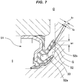
sealing device 51 inFig. 6 mentioned above, a muddy water resistance is necessary for sealing the muddy water as mentioned above, and grease G may be accordingly applied to an inner peripheral surface of theend face lip 52 as shown inFig. 7 . - However, in the
sealing device 51 inFig. 7 mentioned above, the grease G is applied to an inner peripheral surface of a leadingend portion 52b in theend face lip 52 at a comparatively large amount, and is applied to an inner peripheral surface of aroot portion 52a in theend face lip 52 at a comparatively small amount as shown. More specifically, since an application thickness t1 of the grease G applied to the inner peripheral surface of the lip leadingend portion 52b in theend face lip 52 is set to be thicker (larger) than an application thickness t2 of the grease G applied to the inner peripheral surface of thelip root portion 52a (t1 > t2), the applied grease G has a great contact width w1 at which the grease comes into contact with theend face portion 33 of the rotation side part. - Therefore, in the case that the rotation side part rotates at a high speed in a state in which the contact width w1 is great as mentioned above, the grease G passes through the sliding portion of the
end face lip 52 due to a centrifugal force as shown inFig. 8 , and there is fear that the grease is scattered toward a peripheral structure including a brake disk (a grease scattering direction is indicated by an arrow A). Since the attachment of the scattered grease G to the brake disc directly affects a brake performance, it is necessary to avoid the attachment of the grease G as much as possible. - The present invention is made by taking the above points into consideration, and an object of the present invention is to provide a sealing device structured such that a grease applied to an inner peripheral surface of an end face lip is hard to be scattered even in the case that a centrifugal force acts on the sealing device.
- In order to achieve the above object, the present invention employs the following means.
- A sealing device according to the present invention is a sealing device sealing a foreign material in a machine outer side so as to prevent the foreign material from entering into a machine inner side, having an end face lip which slidably comes into contact with an end face portion of a rotation side part, and applying grease for lubrication to an inner peripheral surface of the end face lip, wherein an application amount of the grease applied to an inner peripheral surface of a leading end portion in the end face lip is set to be smaller than an application amount of the grease applied to an inner peripheral surface of a root portion in the end face lip (claim 1).
- In the case that the application amount of the grease applied to the inner peripheral surface of the leading end portion in the end face lip is set to be smaller than the application amount of the grease applied to the inner peripheral surface of the root portion in the end face lip, a contact width of the applied grease coming into contact with the end face portion of the rotation side part becomes smaller in comparison with the conventional one. Accordingly, the applied grease is hard to be affected by the centrifugal force. As a result, it is possible to inhibit the grease from passing through the sliding portion of the end face lip and being scattered.
- In order to set the application amount of the grease applied to the inner peripheral surface of the leading end portion in the end face lip to be smaller than the application amount of the grease applied to the inner peripheral surface of the root portion in the end face lip, the following aspects can be, for example, conceived.
- The grease is applied over a whole peripheral of the inner peripheral surface in the end face lip, and an application thickness of the grease applied to the inner peripheral surface of the leading end portion in the end face is set to be smaller than an application thickness of the grease applied to the inner peripheral surface of the root portion in the end face lip on the assumption thereof (claim 2).
- Further, the grease is applied to a part of a circumference of the inner peripheral surface of the end face lip, and any one or both of an application thickness and an application width in a circumferential direction of the grease applied to the inner peripheral surface of the leading end portion in the end face lip is set to be smaller than an application thickness or an application width in a circumferential direction of the grease applied to the inner peripheral surface of the root portion in the end face lip on the assumption thereof (claim 3).
- Further, it is effective in the present invention that grease trap is provided in an outer peripheral side of the end face lip in preparation for the case that the grease passes through the sliding portion of the end face lip. Since the grease trap collects the grease in the case that the grease trap is provided in the outer peripheral side of the end face lip as mentioned above, it is possible to inhibit the grease from being scattered (claim 4).
- Since the sealing device according to the present invention exerts an effect of preventing the grease from being scattered, the sealing device is suitably used as a hub bearing seal for a vehicle such as a motor vehicle and the other bearing seals which are provided with a structure applying the grease to an inner peripheral surface of an end face lip (claim 5).
- According to the present invention, since the application condition of the grease is set to be different from the conventional one, and the grease trap is provided, it is possible to provide the sealing device structured such that the grease applied to the inner peripheral surface of the end face lip is hard to be scattered even in the case that the centrifugal force acts on the sealing device.
-
-
Fig. 1 is a cross sectional view of a substantial part of a sealing device according to a first embodiment of the present invention; -
Figs. 2A and 2B are cross sectional views of a substantial part of a sealing device according to a modified embodiment of the first embodiment of the present invention; -
Fig. 3 is a cross sectional view of a substantial part of a sealing device according to a second embodiment of the present invention; -
Fig. 4 is a cross sectional view of a substantial part of a sealing device according to a third embodiment of the present invention; -
Fig. 5 is a cross sectional view of a substantial part of a sealing device according to a fourth embodiment of the present invention; -
Fig. 6 is a cross sectional view of a substantial part of a sealing device according to a conventional example; -
Fig. 7 is a cross sectional view of a substantial part of a sealing device according to the other conventional example; and -
Fig. 8 is a cross sectional view of a substantial part and shows a state in which a grease is scattered in the sealing device. - The following embodiments are included in the present invention.
- (1) In order to prevent the grease from being scattered to a peripheral structure, the hub seal having the following specification is proposed.
- (2) Application amount distribution of grease
- (2-1) An application amount distribution of the grease applied to the side lip is set to the following specification. More specifically, the grease application amount is set to be comparatively smaller toward the lip leading end from the vicinity of the lip root, thereby achieving the specification that at the on-shaft time the applied grease (except the lip leading end portion) does not come into contact with a bearing inner ring.
- (2-2) Grease application aspect is provided so that the grease does not come into contact with the bearing inner ring while keeping the grease lubrication in the lip leading end portion and maintaining the muddy water resistance on the basis of the above structure, thereby achieving the specification that the grease is hard to be scattered to the outer peripheral side of the seal.
- Next, a description will be given of embodiments according to the present invention with reference to the accompanying drawings.
-
Fig. 1 shows a cross section of a substantial part of asealing device 1 according to a first embodiment of the present invention. Thesealing device 1 according to the embodiment is used as a hub bearing seal (a hub seal) in a bearing portion in a wheel suspension device for a motor vehicle, and is structured as follows. - More specifically, the sealing device is provided with a
mounting ring 11 which is fixed to an inner peripheral surface of ahousing 31 such as a bearing outer ring corresponding to a stationary side mounting part in the bearing portion and is made of a rigid material such as a metal, and a rubber-likeelastic body 21 made of a predetermined rubber material is attached (crosslinking bonded) to themounting ring 11. - The
mounting ring 11 has atubular portion 12 which is fitted and attached to an inner peripheral surface of thehousing 31, and a radiallyinward flange portion 14 is integrally formed in an end portion in one side (a right side in the drawing) in an axial direction of thetubular portion 12 via abent portion 13. - The rubber-like
elastic body 21 is attached to thebent portion 13 and theflange portion 14 in themounting ring 11, and an outerperipheral seal portion 22, an end face lip (a side lip) 23, a second end face lip (a second side lip) 24 and a radial lip (a grease lip) 25 are integrally formed by the rubber-likeelastic body 21. The outerperipheral seal portion 22 comes into contact with an inner peripheral surface of thehousing 31 in a stationary manner. Theend face lip 23 slidably comes into contact with an end face portion (an end face portion in an axial direction) 33 of ashaft 32 such as a bearing inner ring corresponding to a rotation side part in the bearing portion. The secondend face lip 24 slidably comes into contact with theend face portion 33 of theshaft 32 in the same manner in an inner peripheral side of theend face lip 23. Theradial lip 25 slidably comes into contact with an outerperipheral surface portion 34 of theshaft 32 in a bearing inner portion (a machine inner side) I side of the secondend face lip 24. A round portion having a circular arc cross sectional shape is included in theend face portion 33 as shown in the drawing. - The
end face lip 23 and the secondend face lip 24 are respectively formed so that diameters thereof are enlarged little by little fromlip root portions end portions end portions end portions end face portion 33 of theshaft 32. - Grease G constructed by fluid having viscosity is applied to each of the inner peripheral surfaces of the
lips lips - Among them, the grease G applied to the inner peripheral surface of the
end face lip 23 is set to be applied to an inner peripheral surface of a leadingend portion 23b in theend face lip 23 at a comparatively small amount and be applied to an inner peripheral surface of aroot portion 23a in theend face lip 23 at a comparatively large amount. More specifically, the grease G is applied over a whole periphery of the inner peripheral surface of theend face lip 23, and an application thickness t1 of the grease G applied to the inner peripheral surface of the leadingend portion 23b in theend face lip 23 is set to be smaller than an application thickness t2 of the grease G applied to the inner peripheral surface of theroot portion 23a in the end face lip 23 (t1 < t2). Further, the application thickness of the grease G is set to be enlarged little by little from the lip leadingend portion 23b toward thelip root portion 23a, and is on the contrary set to become smaller little by little from thelip root portion 23a toward the lip leadingend portion 23b. - In the
sealing device 1 having the structure mentioned above, the grease G is set to be applied to the inner peripheral surface of the leadingend portion 23b in theend face lip 23 at the comparatively small amount and be applied to the inner peripheral surface of theroot portion 23a in theend face lip 23 at the comparatively large amount, and the application thickness t1 of the grease G applied to the inner peripheral surface of the leadingend portion 23b in theend face lip 23 is set to be smaller than the application thickness t2 of the grease G applied to the inner peripheral surface of theroot portion 23a in theend face lip 23. As a result, in correspondence to the application thickness t1 of the grease G applied to the inner peripheral surface of the lip leadingend portion 23b in the former, a contact width w2 of the applied grease with theend face portion 33 of theshaft 32 is set to be much smaller in comparison with a contact width w1 in the prior art shown inFig. 7 mentioned above (w1 > w2). Even in the case that the centrifugal force is generated in conjunction with the rotation of theshaft 32 under the structure mentioned above, the centrifugal force is hard to affect the grease G. As a result, it is possible to inhibit the grease G from passing through the sliding portion of theend face lip 23 and being scattered toward an outer peripheral side thereof. - As mentioned above, the present invention is characterized in that the application amount of the grease G applied to the inner peripheral surface of the lip leading
end portion 23b in theend face lip 23 is set to be smaller than the application amount of the grease G applied to the inner peripheral surface of theroot portion 23a in theend face lip 23. In order to realize this, in the first embodiment mentioned above, the grease G is applied over the whole periphery of the inner peripheral surface in theend face lip 23, and the application thickness t1 of the grease G applied to the inner peripheral surface of theleading end portion 23b in theend face lip 23 is set to be smaller than the application thickness t2 of the grease G applied to the inner peripheral surface of theroot portion 23a in the end face lip 23 (t1 < t2). However, the grease G may be applied to a part of a circumference of the inner peripheral surface of theend face lip 23. A description will be given below of an example in this case. - More specifically, in the example shown in
Fig. 2A , the grease G is applied to a plurality of positions in a part of the circumference of the inner peripheral surface of theend face lip 23, and an application width c1 in a circumferential direction of the grease G applied to the inner peripheral surface of theleading end portion 23b in theend face lip 23 is set to be smaller than an application width c2 in a circumferential direction of the grease G applied to the inner peripheral surface of theroot portion 23a in the end face lip 23 (c1 < c2). The application thickness t of the grease is set to be fixed or approximately fixed. - Further, in an example shown in
Fig. 2B , the grease G is applied to a plurality of positions in a part of the circumference of the inner peripheral surface of theend face lip 23, and the application width c1 in the circumferential direction of the grease G applied to the inner peripheral surface of theleading end portion 23b in theend face lip 23 is set to be smaller than the application width c2 in the circumferential direction of the grease G applied to the inner peripheral surface of theroot portion 23a in the end face lip 23 (c1 < c2). In addition, the application thickness t1 of the grease G applied to the inner peripheral surface of theleading end portion 23b in theend face lip 23 is set to be smaller than the application thickness t2 of the grease G applied to the inner peripheral surface of theroot portion 23a in the end face lip 23 (t1 < t2). - In these structures, it is possible to provide the sealing device having the structure in which the grease G applied to the inner peripheral surface of the
end face lip 23 is hard to be scattered. -
Fig. 3 shows a cross section of a substantial part of asealing device 1 according to a second embodiment of the present invention. Thesealing device 1 according to the embodiment is used as a hub bearing seal (a hub seal) in a bearing portion in a wheel suspension device for a motor vehicle, and is structured as follows. - More specifically, the sealing device is provided with a mounting
ring 11 which is fixed to an inner peripheral surface of ahousing 31 such as a bearing outer ring corresponding to a stationary side mounting part in the bearing portion and is made of a rigid material such as a metal, and a rubber-likeelastic body 21 made of a predetermined rubber material is attached (crosslinking bonded) to the mountingring 11. - The mounting
ring 11 has atubular portion 12 which is fitted and attached to an inner peripheral surface of thehousing 31, and a radiallyinward flange portion 14 is integrally formed in an end portion in one side (a left side in the drawing) in an axial direction of thetubular portion 12 via abent portion 15 and an innerperipheral tube portion 16. Further, a radiallyoutward flange portion 17 is integrally formed in an end portion in the other side (a right side in the drawing) in the axial direction of thetubular portion 12. - The rubber-like
elastic body 21 is attached to thetubular portion 12, thebent portion 15, the innerperipheral portion 16 and both theflange portions ring 11, and an endface seal portion 26, an outerperipheral cover portion 27, an end face lip (a side lip) 23, a second end face lip (a second side lip) 24 and a radial lip (a grease lip) 25 are integrally formed by the rubber-likeelastic body 21. The endface seal portion 26 comes into contact with an end face portion of thehousing 31 in a stationary manner. The outerperipheral cover portion 27 covers theoutward flange portion 17 of the mountingring 11. The end facelip 23 slidably comes into contact with an end face portion (an end face portion in an axial direction) 33 of ashaft 32 such as a bearing inner ring corresponding to a rotation side part in the bearing portion. The secondend face lip 24 slidably comes into contact with theend face portion 33 of theshaft 32 in the same manner in an inner peripheral side of theend face lip 23. Theradial lip 25 slidably comes into contact with an outerperipheral surface portion 34 of theshaft 32 in a bearing inner portion (a machine inner side) I side of the secondend face lip 24. A round portion having a circular arc cross sectional shape is included in theend face portion 33 as shown in the drawing. - The end face
lip 23 and the secondend face lip 24 are respectively formed so that diameters thereof are enlarged little by little from thelip root portions end portions end portions end portions end face portion 33 of theshaft 32. - Grease G constructed by fluid having a viscosity is applied to each of inner peripheral surfaces of the
lips lips - Among them, the grease G applied to the inner peripheral surface of the
end face lip 23 is set to be applied to an inner peripheral surface of aleading end portion 23b in theend face lip 23 at a comparatively small amount and be applied to an inner peripheral surface of aroot portion 23a in theend face lip 23 at a comparatively large amount. More specifically, the grease G is applied over a whole periphery of the inner peripheral surface of theend face lip 23, and an application thickness t1 of the grease G applied to the inner peripheral surface of theleading end portion 23b in theend face lip 23 is set to be smaller than an application thickness t2 of the grease G applied to the inner peripheral surface of theroot portion 23a in the end face lip 23 (t1 < t2). Further, the application thickness of the grease G is set to be enlarged little by little from the lip leadingend portion 23b toward thelip root portion 23a, and is on the contrary set to become smaller little by little from thelip root portion 23a toward the lip leadingend portion 23b. - Further,
grease trap 28 is provided so as to be positioned in an outer peripheral side of theend face lip 23. - The
grease trap 28 is formed into an annular shape and a lip shape, and is formed into such a shape that an inner diameter thereof is decreased little by little from atrap root portion 28a toward a trap leadingend portion 28b of thegrease trap 28. Further, thegrease trap 28 is integrally formed with the outerperipheral cover portion 27 by the rubber-likeelastic body 21, and slidably comes into contact with theend face portion 33 of theshaft 32 with theleading end portion 28b thereof. - In the
sealing device 1 having the structure mentioned above, the grease G is set to be applied to the inner peripheral surface of theleading end portion 23b in theend face lip 23 at the comparatively small amount and be applied to the inner peripheral surface of theroot portion 23a in theend face lip 23 at the comparatively large amount, and the application thickness t1 of the grease G applied to the inner peripheral surface of theleading end portion 23b in theend face lip 23 is set to be smaller than the application thickness t2 of the grease G applied to the inner peripheral surface of theroot portion 23a in theend face lip 23. As a result, in correspondence to the application thickness t1 of the grease G applied to the inner peripheral surface of the lip leadingend portion 23b in the former, a contact width w2 of the applied grease with theend face portion 33 of theshaft 32 is set to be much smaller in comparison with a contact width w1 in the prior art shown inFig. 7 mentioned above (w1 > w2). Even in the case that the centrifugal force is generated in conjunction with the rotation of theshaft 32 under the structure mentioned above, the centrifugal force is hard to affect the grease G. As a result, it is possible to inhibit the grease G from passing through the sliding portion of theend face lip 23 and being scattered toward an outer peripheral side thereof. - Further, since the
grease trap 28 is previously provided in the outer peripheral side of theend face lip 23 in preparation for the case that the grease G passes through the sliding portion of theend face lip 23, thegrease trap 28 can collect the grease G. Therefore, it is possible to inhibit the grease G from being scattered toward the outer peripheral side from thesealing device 1. - The
grease trap 28 is formed into the annular shape and the lip shape, and is formed into such the shape that the inner diameter is decreased little by little from thetrap root portion 28a toward the trap leadingend portion 28b of thegrease trap 28. Therefore, the collected grease G flows along an inner peripheral surface of thegrease trap 28 from the trap leadingend portion 28b side toward thetrap root portion 28a side and is hard to flow out of the trap leadingend portion 28b. As a result, an effect of collecting the grease is high. - In the first and second embodiments, the
end face lip 23 is structured such that theend face lip 23 slidably comes into contact with the end face portion (the end portion in the axial direction) 33 of the flange portion which is provided in theshaft 32 such as the bearing inner ring corresponding to the other end of sliding, however, the other end of sliding may be set to the other part than the flange portion provided in theshaft 32, for example, may be set to a metal ring which is mounted to an outer peripheral surface of theshaft 32. A description will be given below of an example in this case. -
Fig. 4 shows a cross section of a substantial part of asealing device 1 according to a third embodiment of the present invention. Thesealing device 1 according to the embodiment is used as a hub bearing seal (a hub seal) in a bearing portion in a wheel suspension device for a motor vehicle, and is combined with ametal ring 41 which is mounted to an outer peripheral surface of theshaft 32. - The
metal ring 41 has atubular portion 42 which is fitted to the outer peripheral surface of theshaft 32, and a radiallyoutward flange portion 44 is integrally formed in an end portion in one side (a bearing outer portion (a machine outer side) O, a right side in the drawing) in an axial direction of thetubular portion 42. Thismetal ring 41 is also called as a "slinger". - The sealing device is provided with a mounting
ring 11 which is fixed to an inner peripheral surface of ahousing 31 such as a bearing outer ring corresponding to a stationary side mounting part in the bearing portion and is made of a rigid material such as a metal, and a rubber-likeelastic body 21 made of a predetermined rubber material is attached (crosslinking bonded) to the mountingring 11. - The mounting
ring 11 has atubular portion 12 which is fitted and attached to an inner peripheral surface of thehousing 31, and a radiallyinward flange portion 14 is integrally formed in an end portion in the other side (a bearing inner portion (a machine inner side) I, a left side in the drawing) in an axial direction of thetubular portion 12 via abent portion 13. - The rubber-like
elastic body 21 is attached to thetubular portion 12, thebent portion 13 and theflange portion 14 in the mountingring 11, and an outerperipheral seal portion 22, an end face lip (a side lip) 23, aradial lip 29 and a radial lip (a grease lip) 25 are integrally formed by the rubber-likeelastic body 21. The outerperipheral seal portion 22 comes into contact with an inner peripheral surface of thehousing 31 in a stationary manner. The end facelip 23 slidably comes into contact with an end face portion (a machine inner side end face portion) 45 of theflange portion 44 in themetal ring 41. Theradial lip 29 slidably comes into contact with the outerperipheral surface portion 43 of thetubular portion 42 in themetal ring 41 in an inner peripheral side of theend face lip 23. Theradial lip 25 slidably comes into contact with an outerperipheral surface portion 43 of thetubular portion 42 in themetal ring 41 in the same manner in a machine inner side of theradial lip 29. - The end face
lip 23 is formed so that a diameter thereof is enlarged little by little from alip root portion 23a toward lip leadingend portion 23b, is provided with the lip leadingend portion 23b so as to be directed to an outer peripheral side, and mainly exerts a sealing function so as to prevent a foreign material such as muddy water in a bearing outer portion (a machine outer side) O from entering into the machine inner side I on the basis of the lip leadingend portion 23b slidably coming into contact with the end face portion (the machine inner side end face portion) 45 of theflange portion 44 in themetal ring 41. - Grease G constructed by fluid having viscosity is applied to each of the inner peripheral surfaces of the
lips lips - Among them, the grease G applied to the inner peripheral surface of the
end face lip 23 is set to be applied to an inner peripheral surface of aleading end portion 23b in theend face lip 23 at a comparatively small amount and be applied to an inner peripheral surface of aroot portion 23a in theend face lip 23 at a comparatively large amount. More specifically, the grease G is applied over a whole periphery of the inner peripheral surface of theend face lip 23, and an application thickness t1 of the grease G applied to the inner peripheral surface of theleading end portion 23b in theend face lip 23 is set to be smaller than an application thickness t2 of the grease G applied to the inner peripheral surface of theroot portion 23a in the end face lip 23 (t1 < t2). Further, the application thickness of the grease G is set to be enlarged little by little from the lip leadingend portion 23b toward thelip root portion 23a, and is on the contrary set to become smaller little by little from thelip root portion 23a toward the lip leadingend portion 23b. - In the
sealing device 1 having the structure mentioned above, the grease G is set to be applied to the inner peripheral surface of theleading end portion 23b in the end face lip at the comparatively small amount and be applied to the inner peripheral surface of theroot portion 23a in theend face lip 23 at the comparatively large amount, and the application thickness t1 of the grease G applied to the inner peripheral surface of theleading end portion 23b in theend face lip 23 is set to be smaller than the application thickness t2 of the grease G applied to the inner peripheral surface of theroot portion 23a in theend face lip 23. As a result, in correspondence to the application thickness t1 of the grease G applied to the inner peripheral surface of the lip leadingend portion 23b in the former, a contact width w2 of the applied grease with theend face portion 33 of theshaft 32 is set to be much smaller in comparison with a contact width w1 in the prior art shown inFig. 7 mentioned above (w1 > w2). Even in the case that the centrifugal force is generated in conjunction with the rotation of theshaft 32 under the structure mentioned above, the centrifugal force is hard to affect the grease G. As a result, it is possible to inhibit the grease G from passing through the sliding portion of theend face lip 23 and being scattered toward an outer peripheral side thereof. - The grease G may be applied to the part of the circumference of the inner peripheral surface of the
end face lip 23 as mentioned above. - Further, as shown in
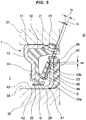
Fig. 5 as a fourth embodiment, themetal ring 41 may be ametal ring 41 with amagnetic encoder 47. - The
magnetic encoder 47 is formed into an annular shape with a predetermined rubber-like elastic material obtained by mixing a magnetic powder, and is structured such that a lot of N poles and S poles are alternately magnetized circumferentially at predetermined pitches to form a circumferential magnetic pattern. Themagnetic encoder 47 senses a speed of rotation and an angle of rotation of an axis by being combined with a magnetic sensor (not shown). - In the embodiment, the
magnetic encoder 47 as mentioned above is attached (crosslinking bonded) to anend face portion 46 in a machine outer side of theflange portion 44 in themetal ring 41, and is structured such that theend face lip 23 slidably comes into contact with anend face portion 45 in a machine inner side of theflange portion 44. - In the fourth embodiment, the other structures and operational effects are the same as the third embodiment mentioned above. Therefore, a description thereof will be omitted by attaching the same reference numerals.
- The
sealing device 1 according to the second embodiment (Fig. 3 ) is thesealing device 1 sealing the foreign material in the machine outer side O so as to prevent the foreign material from entering into the machine inner side I, in which the sealing device has theend face lips end face portion 33 of the rotation side part (the shaft) 32, and applies the lubricating grease G to the inner peripheral surfaces of theend face lips - (A) the application amount of the grease G applied to the inner peripheral surfaces of the
leading end portions end face lips root portions end face lips - (B) the
grease trap 28 is provided in the outer peripheral side of theend face lips - The structure (B) can exert the effect of suppressing the scattering of the grease G by itself. Therefore, the invention in this case can be defined by the following structure.
- A sealing device sealing a foreign material in a machine outer side so as to prevent the foreign material from entering into a machine inner side, having an end face lip which slidably comes into contact with an end face portion of a rotation side part, and applying grease for lubrication to an inner peripheral surface of the end face lip, wherein grease trap is provided in an outer peripheral side of the end face lip.
- The sealing device described in the item (B-1) mentioned above, wherein the grease trap is formed into a lip shape, and an inner diameter of the grease trap is formed into such a shape that is decreased little by little from a root portion toward a leading end portion of the grease trap.
- The sealing device described in the item (B-1) or (B-2) mentioned above, wherein the sealing device is used as a hub bearing seal for a vehicle such as a motor vehicle or the other bearing seals.
-
- 1
- sealing device
- 11
- mounting ring
- 12, 42
- tubular portion
- 13, 15
- bent portion
- 14, 17, 44
- flange portion
- 16
- inner peripheral tube portion
- 21
- rubber-like elastic body
- 22
- outer peripheral seal portion
- 23
- end face lip
- 23a, 24a
- lip root portion
- 23b, 24b
- lip leading end portion
- 24
- second end face lip
- 25
- radial lip
- 26
- end face seal portion
- 27
- outer peripheral cover portion
- 28
- grease trap
- 28a
- trap root portion
- 28b
- trap leading end portion
- 31
- housing
- 32
- shaft
- 33, 45, 46
- end face portion
- 34, 43
- outer peripheral surface portion
- 41
- metal ring
- 47
- magnetic encoder
- G
- grease
- I
- machine inner side
- O
- machine outer side
Claims (5)
- A sealing device sealing a foreign material in a machine outer side so as to prevent the foreign material from entering into a machine inner side, the sealing device comprising:an end face lip which slidably comes into contact with an end face portion of a rotation side part;the sealing device applying grease for lubrication to an inner peripheral surface of the end face lip; andan application amount of the grease applied to an inner peripheral surface of a leading end portion in the end face lip being set to be smaller than an application amount of the grease applied to an inner peripheral surface of a root portion in the end face lip.
- The sealing device according to claim 1, wherein the grease is applied over a whole peripheral of the inner peripheral surface in the end face lip, and
wherein an application thickness of the grease applied to the inner peripheral surface of the leading end portion in the end face is set to be smaller than an application thickness of the grease applied to the inner peripheral surface of the root portion in the end face lip. - The sealing device according to claim 1, wherein the grease is applied to a part of a circumference of the inner peripheral surface of the end face lip, and
wherein any one or both of an application thickness and an application width in a circumferential direction of the grease applied to the inner peripheral surface of the leading end portion in the end face lip is set to be smaller than an application thickness or an application width in a circumferential direction of the grease applied to the inner peripheral surface of the root portion in the end face lip. - The sealing device according to any one of claims 1 to 3, wherein a grease trap is provided in an outer peripheral side of the end face lip.
- The sealing device according to any one of claims 1 to 4, wherein the sealing device is used as a hub bearing seal for a vehicle such as a motor vehicle or the other bearing seals.
Applications Claiming Priority (4)
| Application Number | Priority Date | Filing Date | Title |
|---|---|---|---|
| JP2015104428 | 2015-05-22 | ||
| JP2015104429 | 2015-05-22 | ||
| JP2015172056 | 2015-09-01 | ||
| PCT/JP2016/064674 WO2016190175A1 (en) | 2015-05-22 | 2016-05-18 | Sealing device |
Publications (2)
| Publication Number | Publication Date |
|---|---|
| EP3299683A1 true EP3299683A1 (en) | 2018-03-28 |
| EP3299683A4 EP3299683A4 (en) | 2018-05-30 |
Family
ID=57393191
Family Applications (1)
| Application Number | Title | Priority Date | Filing Date |
|---|---|---|---|
| EP16799881.4A Withdrawn EP3299683A4 (en) | 2015-05-22 | 2016-05-18 | Sealing device |
Country Status (6)
| Country | Link |
|---|---|
| US (1) | US20180156277A1 (en) |
| EP (1) | EP3299683A4 (en) |
| JP (1) | JPWO2016190175A1 (en) |
| KR (1) | KR20180011128A (en) |
| CN (1) | CN107532722A (en) |
| WO (1) | WO2016190175A1 (en) |
Cited By (1)
| Publication number | Priority date | Publication date | Assignee | Title |
|---|---|---|---|---|
| EP3882497A4 (en) * | 2018-11-12 | 2022-01-05 | NOK Corporation | SEALING DEVICE AND GREASE ADHESION PROCESS |
Families Citing this family (5)
| Publication number | Priority date | Publication date | Assignee | Title |
|---|---|---|---|---|
| CN109416079B (en) * | 2016-06-20 | 2021-02-09 | Nok株式会社 | Sealing means |
| CN110036214B (en) * | 2016-11-25 | 2020-11-24 | Nok株式会社 | Sealing device and sealing structure |
| JP7118781B2 (en) * | 2018-07-09 | 2022-08-16 | Nok株式会社 | sealing device |
| JP7417973B2 (en) * | 2019-03-18 | 2024-01-19 | 内山工業株式会社 | bearing sealing device |
| JP2021017976A (en) * | 2019-07-17 | 2021-02-15 | 光洋シーリングテクノ株式会社 | Sealing device for hub unit |
Family Cites Families (6)
| Publication number | Priority date | Publication date | Assignee | Title |
|---|---|---|---|---|
| JP2007211792A (en) * | 2006-02-07 | 2007-08-23 | Ntn Corp | Wheel bearing |
| JP2008151174A (en) * | 2006-12-14 | 2008-07-03 | Uchiyama Mfg Corp | Sealing device |
| JP2010071323A (en) * | 2008-09-16 | 2010-04-02 | Nok Corp | Sealing device |
| JP2010185490A (en) * | 2009-02-10 | 2010-08-26 | Uchiyama Manufacturing Corp | Bearing sealing device |
| JP2012154373A (en) * | 2011-01-24 | 2012-08-16 | Ntn Corp | Wheel bearing seal |
| JP5918556B2 (en) * | 2012-02-07 | 2016-05-18 | Ntn株式会社 | Wheel bearing device |
-
2016
- 2016-05-18 WO PCT/JP2016/064674 patent/WO2016190175A1/en not_active Ceased
- 2016-05-18 KR KR1020177034872A patent/KR20180011128A/en not_active Withdrawn
- 2016-05-18 CN CN201680024284.5A patent/CN107532722A/en active Pending
- 2016-05-18 EP EP16799881.4A patent/EP3299683A4/en not_active Withdrawn
- 2016-05-18 JP JP2017520641A patent/JPWO2016190175A1/en active Pending
- 2016-05-18 US US15/576,015 patent/US20180156277A1/en not_active Abandoned
Cited By (2)
| Publication number | Priority date | Publication date | Assignee | Title |
|---|---|---|---|---|
| EP3882497A4 (en) * | 2018-11-12 | 2022-01-05 | NOK Corporation | SEALING DEVICE AND GREASE ADHESION PROCESS |
| US11927218B2 (en) | 2018-11-12 | 2024-03-12 | Nok Corporation | Sealing device and method for applying grease thereto |
Also Published As
| Publication number | Publication date |
|---|---|
| KR20180011128A (en) | 2018-01-31 |
| EP3299683A4 (en) | 2018-05-30 |
| JPWO2016190175A1 (en) | 2018-02-15 |
| WO2016190175A1 (en) | 2016-12-01 |
| CN107532722A (en) | 2018-01-02 |
| US20180156277A1 (en) | 2018-06-07 |
Similar Documents
| Publication | Publication Date | Title |
|---|---|---|
| US20180156277A1 (en) | Sealing device | |
| CN107923540B (en) | Sealing means | |
| US11585380B2 (en) | Seal member, and bearing device for wheel with seal member | |
| CN107269711B (en) | Low friction sealing device and rolling bearing equipped therewith | |
| CN108027066B (en) | Sealing means | |
| CN103052819A (en) | Sealing assembly for a rolling bearing | |
| WO2006132083A1 (en) | Sealing device | |
| JP2014240676A (en) | Wheel supporting bearing unit with seal | |
| JP5896115B2 (en) | Sealing device | |
| CN114514383B (en) | Sealing means | |
| US20110193294A1 (en) | Sealing device | |
| US20090108539A1 (en) | Annular Sealing Assembly, in Particular for Wheel Hubs | |
| CN112303129B (en) | Sealing device | |
| JP7401974B2 (en) | Bearing device for wheels | |
| JP2018194106A (en) | Hub unit bearing | |
| KR101573401B1 (en) | Seal assembly and Wheel bearing using the same for vehicle | |
| JP2009197969A (en) | Sealing device for rolling bearing | |
| JP2008014384A (en) | Sealing device | |
| JP2017106574A (en) | Sealing device and hub unit bearing with sealing device | |
| KR101595560B1 (en) | Encoder seal assembly and Wheel bearing using the same for vehicle | |
| JP7175170B2 (en) | sealing device | |
| CN114673791A (en) | Sealing means | |
| JP2006083981A (en) | Sealing device | |
| CN203702886U (en) | Bearing unit with rotational speed detection device | |
| KR101857190B1 (en) | Pack seal and wheel bearing for vehicle using the same |
Legal Events
| Date | Code | Title | Description |
|---|---|---|---|
| PUAI | Public reference made under article 153(3) epc to a published international application that has entered the european phase |
Free format text: ORIGINAL CODE: 0009012 |
|
| 17P | Request for examination filed |
Effective date: 20171124 |
|
| AK | Designated contracting states |
Kind code of ref document: A1 Designated state(s): AL AT BE BG CH CY CZ DE DK EE ES FI FR GB GR HR HU IE IS IT LI LT LU LV MC MK MT NL NO PL PT RO RS SE SI SK SM TR |
|
| AX | Request for extension of the european patent |
Extension state: BA ME |
|
| A4 | Supplementary search report drawn up and despatched |
Effective date: 20180426 |
|
| RIC1 | Information provided on ipc code assigned before grant |
Ipc: F16J 15/3232 20160101AFI20180420BHEP Ipc: F16C 33/78 20060101ALI20180420BHEP Ipc: F16C 41/00 20060101ALI20180420BHEP |
|
| DAV | Request for validation of the european patent (deleted) | ||
| DAX | Request for extension of the european patent (deleted) | ||
| STAA | Information on the status of an ep patent application or granted ep patent |
Free format text: STATUS: THE APPLICATION IS DEEMED TO BE WITHDRAWN |
|
| 18D | Application deemed to be withdrawn |
Effective date: 20181127 |