EP3298633B1 - Ultrasonic transducer - Google Patents
Ultrasonic transducer Download PDFInfo
- Publication number
- EP3298633B1 EP3298633B1 EP16797340.3A EP16797340A EP3298633B1 EP 3298633 B1 EP3298633 B1 EP 3298633B1 EP 16797340 A EP16797340 A EP 16797340A EP 3298633 B1 EP3298633 B1 EP 3298633B1
- Authority
- EP
- European Patent Office
- Prior art keywords
- substrate
- active device
- membrane
- electromechanically active
- ultrasonic transducer
- Prior art date
- Legal status (The legal status is an assumption and is not a legal conclusion. Google has not performed a legal analysis and makes no representation as to the accuracy of the status listed.)
- Active
Links
- 239000000758 substrate Substances 0.000 claims description 128
- 239000012528 membrane Substances 0.000 claims description 110
- 239000000463 material Substances 0.000 claims description 56
- 229910052782 aluminium Inorganic materials 0.000 claims description 13
- XAGFODPZIPBFFR-UHFFFAOYSA-N aluminium Chemical compound [Al] XAGFODPZIPBFFR-UHFFFAOYSA-N 0.000 claims description 13
- 239000010410 layer Substances 0.000 description 24
- ZEATXTCWXKQPHO-UHFFFAOYSA-N 1,2,4,5-tetrachloro-3-(3,5-dichlorophenyl)benzene Chemical compound ClC1=CC(Cl)=CC(C=2C(=C(Cl)C=C(Cl)C=2Cl)Cl)=C1 ZEATXTCWXKQPHO-UHFFFAOYSA-N 0.000 description 19
- 239000004593 Epoxy Substances 0.000 description 17
- 239000011149 active material Substances 0.000 description 14
- 238000000034 method Methods 0.000 description 10
- 229910052751 metal Inorganic materials 0.000 description 6
- 239000002184 metal Substances 0.000 description 6
- 239000010703 silicon Substances 0.000 description 6
- 229910000838 Al alloy Inorganic materials 0.000 description 4
- 229910000676 Si alloy Inorganic materials 0.000 description 4
- 239000002648 laminated material Substances 0.000 description 4
- RYGMFSIKBFXOCR-UHFFFAOYSA-N Copper Chemical compound [Cu] RYGMFSIKBFXOCR-UHFFFAOYSA-N 0.000 description 3
- 239000000654 additive Substances 0.000 description 3
- 230000000996 additive effect Effects 0.000 description 3
- 239000000853 adhesive Substances 0.000 description 3
- 230000001070 adhesive effect Effects 0.000 description 3
- 239000010949 copper Substances 0.000 description 3
- 230000005611 electricity Effects 0.000 description 3
- -1 for example Chemical class 0.000 description 3
- 238000004519 manufacturing process Methods 0.000 description 3
- 229910000881 Cu alloy Inorganic materials 0.000 description 2
- 229910001374 Invar Inorganic materials 0.000 description 2
- XUIMIQQOPSSXEZ-UHFFFAOYSA-N Silicon Chemical compound [Si] XUIMIQQOPSSXEZ-UHFFFAOYSA-N 0.000 description 2
- 239000011358 absorbing material Substances 0.000 description 2
- 239000002313 adhesive film Substances 0.000 description 2
- 239000007767 bonding agent Substances 0.000 description 2
- 239000003990 capacitor Substances 0.000 description 2
- 239000000919 ceramic Substances 0.000 description 2
- 229910010293 ceramic material Inorganic materials 0.000 description 2
- 238000006243 chemical reaction Methods 0.000 description 2
- 238000005520 cutting process Methods 0.000 description 2
- 238000005553 drilling Methods 0.000 description 2
- 239000010408 film Substances 0.000 description 2
- 238000002955 isolation Methods 0.000 description 2
- 229910000833 kovar Inorganic materials 0.000 description 2
- 150000002739 metals Chemical class 0.000 description 2
- 239000004033 plastic Substances 0.000 description 2
- 229920003023 plastic Polymers 0.000 description 2
- 229920003223 poly(pyromellitimide-1,4-diphenyl ether) Polymers 0.000 description 2
- 229910052710 silicon Inorganic materials 0.000 description 2
- 229920002379 silicone rubber Polymers 0.000 description 2
- 239000004945 silicone rubber Substances 0.000 description 2
- 229910000679 solder Inorganic materials 0.000 description 2
- 239000010935 stainless steel Substances 0.000 description 2
- 229910001220 stainless steel Inorganic materials 0.000 description 2
- 238000002604 ultrasonography Methods 0.000 description 2
- 229910001369 Brass Inorganic materials 0.000 description 1
- 230000004888 barrier function Effects 0.000 description 1
- 239000010951 brass Substances 0.000 description 1
- 238000005266 casting Methods 0.000 description 1
- 239000003795 chemical substances by application Substances 0.000 description 1
- 239000002131 composite material Substances 0.000 description 1
- 238000010276 construction Methods 0.000 description 1
- 229910052802 copper Inorganic materials 0.000 description 1
- 238000010168 coupling process Methods 0.000 description 1
- 238000005859 coupling reaction Methods 0.000 description 1
- 238000013016 damping Methods 0.000 description 1
- 230000001419 dependent effect Effects 0.000 description 1
- 238000006073 displacement reaction Methods 0.000 description 1
- 230000000694 effects Effects 0.000 description 1
- 238000010894 electron beam technology Methods 0.000 description 1
- 125000003700 epoxy group Chemical group 0.000 description 1
- 230000005284 excitation Effects 0.000 description 1
- 230000001788 irregular Effects 0.000 description 1
- 238000003475 lamination Methods 0.000 description 1
- 238000003801 milling Methods 0.000 description 1
- 239000012811 non-conductive material Substances 0.000 description 1
- 230000010355 oscillation Effects 0.000 description 1
- 230000003071 parasitic effect Effects 0.000 description 1
- 230000010287 polarization Effects 0.000 description 1
- 229920000647 polyepoxide Polymers 0.000 description 1
- 230000001902 propagating effect Effects 0.000 description 1
- 230000035939 shock Effects 0.000 description 1
- 239000002356 single layer Substances 0.000 description 1
- 238000003860 storage Methods 0.000 description 1
- 239000010409 thin film Substances 0.000 description 1
Images


Classifications
-
- B—PERFORMING OPERATIONS; TRANSPORTING
- B06—GENERATING OR TRANSMITTING MECHANICAL VIBRATIONS IN GENERAL
- B06B—METHODS OR APPARATUS FOR GENERATING OR TRANSMITTING MECHANICAL VIBRATIONS OF INFRASONIC, SONIC, OR ULTRASONIC FREQUENCY, e.g. FOR PERFORMING MECHANICAL WORK IN GENERAL
- B06B1/00—Methods or apparatus for generating mechanical vibrations of infrasonic, sonic, or ultrasonic frequency
- B06B1/02—Methods or apparatus for generating mechanical vibrations of infrasonic, sonic, or ultrasonic frequency making use of electrical energy
- B06B1/06—Methods or apparatus for generating mechanical vibrations of infrasonic, sonic, or ultrasonic frequency making use of electrical energy operating with piezoelectric effect or with electrostriction
- B06B1/0644—Methods or apparatus for generating mechanical vibrations of infrasonic, sonic, or ultrasonic frequency making use of electrical energy operating with piezoelectric effect or with electrostriction using a single piezoelectric element
- B06B1/0662—Methods or apparatus for generating mechanical vibrations of infrasonic, sonic, or ultrasonic frequency making use of electrical energy operating with piezoelectric effect or with electrostriction using a single piezoelectric element with an electrode on the sensitive surface
- B06B1/0666—Methods or apparatus for generating mechanical vibrations of infrasonic, sonic, or ultrasonic frequency making use of electrical energy operating with piezoelectric effect or with electrostriction using a single piezoelectric element with an electrode on the sensitive surface used as a diaphragm
-
- B—PERFORMING OPERATIONS; TRANSPORTING
- B06—GENERATING OR TRANSMITTING MECHANICAL VIBRATIONS IN GENERAL
- B06B—METHODS OR APPARATUS FOR GENERATING OR TRANSMITTING MECHANICAL VIBRATIONS OF INFRASONIC, SONIC, OR ULTRASONIC FREQUENCY, e.g. FOR PERFORMING MECHANICAL WORK IN GENERAL
- B06B1/00—Methods or apparatus for generating mechanical vibrations of infrasonic, sonic, or ultrasonic frequency
- B06B1/02—Methods or apparatus for generating mechanical vibrations of infrasonic, sonic, or ultrasonic frequency making use of electrical energy
- B06B1/06—Methods or apparatus for generating mechanical vibrations of infrasonic, sonic, or ultrasonic frequency making use of electrical energy operating with piezoelectric effect or with electrostriction
- B06B1/0603—Methods or apparatus for generating mechanical vibrations of infrasonic, sonic, or ultrasonic frequency making use of electrical energy operating with piezoelectric effect or with electrostriction using a piezoelectric bender, e.g. bimorph
-
- G—PHYSICS
- G10—MUSICAL INSTRUMENTS; ACOUSTICS
- G10K—SOUND-PRODUCING DEVICES; METHODS OR DEVICES FOR PROTECTING AGAINST, OR FOR DAMPING, NOISE OR OTHER ACOUSTIC WAVES IN GENERAL; ACOUSTICS NOT OTHERWISE PROVIDED FOR
- G10K9/00—Devices in which sound is produced by vibrating a diaphragm or analogous element, e.g. fog horns, vehicle hooters or buzzers
- G10K9/12—Devices in which sound is produced by vibrating a diaphragm or analogous element, e.g. fog horns, vehicle hooters or buzzers electrically operated
- G10K9/122—Devices in which sound is produced by vibrating a diaphragm or analogous element, e.g. fog horns, vehicle hooters or buzzers electrically operated using piezoelectric driving means
Definitions
- Electromechanically active devices may be used in a variety of applications.
- electromechanically active devices may be used in transducers, sensors, and, actuators.
- the electromechanically active device may be used to generate soundwaves, including ultrasonic soundwaves through vibration of the electromechanically active device.
- a membrane, or diaphragm may be added to the electromechanically active device to provide additional surface area to move a medium, such as the air, with the vibrations of the electromechanically active device.
- Document WO 2014/143942 A2 discloses an ultrasonic transducer having a membrane and a container having a base wall and at least one wall element. An array of the ultrasonic transducers can be controlled to produce a steerable beam.
- Document WO 2014/164018 A1 discloses a portable electronic device using a tactile vibrator for providing tactile feedback to the user.
- the housing of the electronic device may be made of piezoelectric ceramic material, or a piezoelectric element may be may be coupled to the housing to cause the housing to vibrate.
- Document US 6,445,108 B1 discloses a piezoelectric acoustic component including a diaphragm having a rectangular piezoelectric plate, an insulating cap, and a plate shaped substrate, wherein an acoustic space is provided between the diaphragm and the upper wall of the insulating cap.
- the present invention provides an ultrasonic transducer as defined in the independent claim 1.
- the ultrasonic transducer includes an electromechanically active device, such as a cantilever or flexure, attached to the wall of a cavity in a substrate.
- the electromechanically active device may be made from a laminate material, and includes electrodes.
- the substrate includes a step structure with vias which are in contact with the electrodes of the electromechanically active device.
- the ultrasonic transducer includes a membrane which covers a top surface of the ultrasonic transducer, and is attached to the electromechanically active device.
- the substrate of the ultrasonic may be a layer of a printed circuit board (PCB), or may be a rigid material such as copper or aluminum. A rigid material may be attached to the bottom of the ultrasonic transducer.
- Multiple ultrasonic transducers may be created using the same piece of substrate, forming an electromechanical transducer array.
- the ultrasonic transducer includes a substrate.
- the substrate may be any suitable material, and may be, for example, the top layer of a PCB with any suitable number of layers.
- the top layer of the PCB may be a non-conductive material such as, for example, FR-4.
- the substrate may be in any suitable shape, and the surface of the substrate may be flat, or may be curved or textured in any suitable manner.
- the substrate may include recessed features.
- the substrate may define the structure of the ultrasonic transducer, provide electrical contact, rigidly secure the electromechanically active device and allow a variation of the rigidity with which the electromechanically active device is secured.
- the substrate may form a base for an electromechanical transducer array, which may include a number of ultrasonic transducers.
- Recessed cavities in the substrate may be used to provide positioning and positive alignment during construction of an electromechanical transducer array including a number of ultrasonic transducers.
- the substrate may be made and structured in any suitable manner, for example, using PCB manufacturing techniques. For example, the recessed cavities may be created with mill holes. Layer lamination, dicing saw cuts and epoxy filled vias may be used to create the structure of the substrate. The structure of the substrate may also be created using negative mold casting or an ordering of subtractive processes.
- the substrate may be the top, non-conductive layer of a PCB, which may allow for the breakout of the ultrasonic transducers of the electromechanical transducer array through the conductive layers of the PCB and connecting vias.
- PCB as a substrate may also allow for electrical control circuitry for the electromechanical transducer array to be placed onto the back-side of the PCB of the electromechanical transducer array.
- Other materials such as ceramics, plastics, or metals, including, for example, aluminum, copper, silicon/aluminum alloy, and silicon, which may be coated or anodized to be non-conductive, may also be used as or in the substrate, and may offer differing levels of mechanical support for the cantilevers in the elements of the electromechanical transducer array.
- the substrate may be aluminum, and may be attached to the top layer of a PCB in any suitable manner.
- the substrate may be designed, for example, using sub-dicing with a dicing saw, which may disrupt lateral and parasitic modes of oscillation among electromechanically active devices of the electromechanical transducer array.
- the substrate may be made of materials of any suitable stiffness. The stiffness of the materials of the substrate may determine the rigidity of the base to which the electromechanically active device may be bonded.
- the substrate may be non-planar, and may also be flexible.
- the substrate may be anisotropic.
- the sub-diced sections of the substrate may be left empty, or may be filled with another material, such as an absorbing material such as silicone rubber.
- the cavity of the ultrasonic transducer may be any suitable shape and have any suitable depth.
- the cavity may be circular.
- the electromechanically active device may be attached to the wall of the cavity in any suitable manner.
- a step structure is created on an edge of the cavity, and the electromechanically active device is bonded to the step structure using any suitable adhesive, such as, for example, conductive epoxy.
- the step structure is created by creating an additional cavity in the substrate.
- the additional cavity partially overlaps the cavity, and is shallower than the cavity. This creates a step at the location where the additional cavity overlaps the cavity, and the additional cavity may appear as crescent shape in the substrate.
- a second step is created by creating a channel of any suitable shape in the substrate, partially overlapping the additional cavity.
- the channel is shallower than the additional cavity, creating the second step at the location of the overlap.
- the step and the second step may be aligned.
- the length of the tread, or shelf, or each step in the step structure to which the electromechanically active device may be bonded may determine the resonant free-length of the electromechanically active device.
- the recessed surfaces of the substrate, such as the cavities, may be designed to permit bonds of varying and controllable strength to the electromechanically active device, which may affect the performance of the electromechanically active device and the output of the ultrasonic transducer. Altering the length of the area to which the electromechanically active device may be bonded may affect the frequency and amplitude, or velocity of output, or amplitude, of the ultrasonic transducer.
- the structure of the substrate may provide clearance for the electromechanically active device to move both up and down over any suitable distance.
- the step structure of the substrate may be further defined by trenches, which may be created to any suitable depth, and may cross through each overlap location.
- a trench having the same depth as the cavity may be created at the overlap of the cavity and the additional cavity
- a trench having the same depth as the additional cavity may be created at the overlap of the channel and the additional cavity.
- the trenches may, for example, be used to create a flat front wall, or riser, for the step and the second step.
- the cavity, additional cavity, channel, and trenches may be created in the substrate of the ultrasonic transducer in any suitable manner, including through subtractive processes, such as drilling, milling, and dicing saw cuts, and through additive processes.
- the substrate includes at least two vias.
- the vias are patterned in pairs offset from one another.
- One via of a pair of vias makes electrical contact with an electrode for an electrically passive layer, such as a conductive metal, of an electromechanically active device.
- the electrode contacts the via on the tread of a step of the step structure of the substrate.
- the other via of the pair of vias makes contact with an electrode on an electrically active material, such as a piezoceramic, of the electromechanically active device.
- the electrode contacts the other via on the tread of the other step of the step structure.
- the electrodes may be, for example, thin-film electrodes.
- the vias may be filled with a conductive epoxy so that when a dicing saw is used to create the recesses, such as the step structure, to accommodate the electromechanically active device, there may be reduced risk of losing conductivity at the electrical contact points of the vias.
- the substrate may include any number of vias for a single electromechanically active device.
- the vias may be any suitable combination of blind vias, buried vias, and through vias.
- Other numbers of vias, and different types of connections with two vias may be used to establish electrical connectivity with the ultrasonic transducers of an electromechanical transducer array.
- the connection to an ultrasonic transducer of an electromechanical transducer array may be hot connection to an electromechanically active device, with a common ground.
- the connections to an ultrasonic transducer may be a hot connection and a ground connection, or a positive connection and a negative connection.
- the connections to an ultrasonic transducer may be two hot connections and one ground connection, two ground connection and one hot connection, or a positive connection, a negative connection, and a ground connection.
- the structure of the substrate may allow for electrical isolation between the components of the electromechanical transducer array.
- the ultrasonic transducer includes an electromechanically active device attached to the substrate.
- the electromechanically active device may be a cantilever or flexure, and may be, for example, a piezoceramic unimorph, bimorph, or trimorph.
- the electromechanically active device may include an electrically active material, such as piezoelectric material or piezoceramic, electrostrictive material, or ferroelectric material, which may able to transform electrical excitation into a high-frequency vibration to produce ultrasonic acoustic emissions.
- the geometry of an electromechanically active device may affect the frequency, velocity, force, displacement, capacitance, bandwidth, and efficiency of electromechanical energy conversion produced by the electromechanically active device when driven to output ultrasound and the voltage and current generated by the electromechanically active device and efficiency of electromechanical energy conversion when driven by received ultrasound.
- the electromechanically active device may have a rectangular profile, or may have a profile based on any other suitable geometry, such as, for example, a trapezoidal geometry.
- the geometry of the electromechanically active device may be selected, for example, to tune the balance and other various characteristics of the electromechanically active device.
- the electromechanically active device may be made using single layer of piezoelectric material laminated onto a single passive substrate material.
- the electromechanically active device may also be made with a single piezoelectric layer and multiple passive layers; two piezoelectric layers operating anti-phase, or two piezoelectric layers, operating anti-phase and combined with one or more electrically passive materials.
- Different layers of the electromechanically active device may have different shapes. For example, in a unimorph, a piezoelectric material may be shaped differently from a passive substrate material to which the piezoelectric material is bonded.
- the piezoelectric material, for example, piezoceramic, used in the electromechanically active device may be poled in any suitable manner, with polarization in any suitable direction.
- the electromechanically active device may be any suitable size for use in an ultrasonic transducer, and for vibrating at ultrasonic frequencies.
- the electromechanically active device may have a width of between 0.5 mm and 1.5 mm, a height of between 0.4 mm and 0.5 mm, and a length of between 2.0 and 3.0 mm, though different layers of the electromechanically active device may have different lengths to allow bonding with the stair structure of the substrate.
- the electromechanically active device may be made in any suitable manner, such as, for example, by cutting rectangular geometries from a larger laminate material.
- the laminate material may be made from, for example, an electrically active material, such a piezoceramic, bonded to an electrically inactive substrate, such as, for example, metals such as aluminum, Invar, Kovar, silicon/aluminum alloys, stainless steel, and brass, using any suitable bonding techniques and materials.
- the materials used may be non-optimal for the performance of an individual electromechanically active device. For example, materials may be selected for consistent performance across a larger number of electromechanically active device or for ease of manufacture.
- An electromechanically active device may include a tail which may be used in securing the electromechanically active device onto the substrate of the ultrasonic transducer, and may facilitate electrical contact, for example, with a via in the substrate.
- the tail of the electromechanically active device may protrude beyond the substrate of the ultrasonic transducer.
- the tail may be structured through a subtractive process, for example, with ceramic material being cut away from the electromechanically active device.
- An additive process may also be used, for, example, with the piezoelectric layer of a laminate material first structured to the desired geometry and then bonded onto the passive substrate material with a pitch approximately equal to the desired length of the electromechanically active device, after which the rectangular electromechanically active device may be cut out of the bonded materials.
- the electromechanically active device may be oriented in the cavity at any suitable angle.
- the electromechanically active device may oriented along a diameter of a circular cavity, and may reach approximately halfway across the cavity.
- the top surface of the electromechanically active device which may be, for example, a passive material of a unimorph or an active material of a bimorph, may be level, or near-level, with the top of the cavity.
- the electromechanically active device may be attached to the substrate of an ultrasonic transducer in any suitable manner.
- any of the underside or both sides of the electromechanically active device may be bonded to the substrate, for example, at the step structure of the substrate.
- the bonds used to secure the electromechanically active device to the substrate may be any suitable combination of organic or inorganic bonds, using any suitable conductive and non-conductive bonding materials, such as, for example, epoxies or solders.
- the area of contact between the electromechanically active device and the substrate may be any suitable size and shape.
- an ultrasonic transducer may include more than one electromechanically active device within a cavity.
- the ultrasonic device may include any number of ultrasonic transducers in any suitable arrangement.
- the electromechanically active device may be bonded in a suitable position on the substrate, with the passive or active layers of the electromechanically active device facing down depending on whether the electromechanically active device is a unimorph, bimorph, trimorph, or has some other structure.
- the bond may use any suitable bonding agent, solder, or epoxy.
- conductive adhesive film may be applied to the areas of the electromechanically active device to be bonded to the substrate.
- the electromechanically active device may be pressed into the substrate and drawn back so that a back wall of the electromechanically active device may be pulled flush against the step structure of the substrate.
- the electromechanically active device may be placed onto the substrate by, for example, a pick and place machine using a UV release tape to pick up the electromechanically active device.
- the conductive adhesive film may be cured, after which the electromechanically active device may be separated from the UV release type by exposure to the release agent, for example, UV light.
- the area to which an electromechanically active device may be bonded may extend outside a single ultrasonic transducer and into a neighboring ultrasonic transducer in an electromechanical transducer array, making use of otherwise unused space on the opposite side of each ultrasonic transducer. This may result in a small additional space at one edge of the electromechanical transducer array.
- a membrane is bonded to the ultrasonic transducer to create an ultrasonic device with a membrane.
- a membrane may be attached with adhesive in a manner that may define the outline of a number of cells of the electromechanical transducer array which the membrane will cover, where each cell may include an ultrasonic transducer.
- the electromechanically active device of a covered ultrasonic transducer is bonded to the membrane, for example, at or near the tip of the electromechanically active device.
- a membrane may be multiple separate pieces of material, each of which may cover one ultrasonic transducer, or multiple ultrasonic transducers, or may be single piece of material which may cover all of the ultrasonic transducers of the electromechanical transducer array.
- a membrane may be aligned with one or more ultrasonic transducers and pressed into the substrate to form a covering layer.
- a membrane may act to acoustically couple the motion of cantilevers to the air, as the motion of cantilevers may cause the membrane to move.
- a membrane may be attached to the substrate in any other suitable manner, such as, for example, being melted or welded to, including being ultrasonically welded, laser welded, or electron beam welded to, or mechanically attached or pinned to, the substrate.
- the membrane may be bonded to the substrate, for example, using any suitable epoxy applied in any suitable manner.
- the membrane may be any suitable material or composite material structure, which may be of any suitable stiffness and weight, for vibrating at ultrasonic frequencies.
- the membrane may be both stiff and light.
- the membrane may be aluminum shim stock, metal-patterned Kapton, or any other metal-pattern film.
- the membrane may be impedance matched with the air to allow for more efficient air-coupling of the ultrasonic transducers.
- the membrane may include additional structures, such as, for example, ring structures located on the membrane where the membrane will contact the tips of the electromechanically active devices.
- the membrane may be attached to an electromechanical transducer array along bond lines, which may be, for example, cured epoxy.
- the bond lines may divide the electromechanical transducer array into ultrasonic transducer cells of any suitable shape, such as squares.
- the membrane may also be bonded to the tips of the free end of each electromechanically active device of the electromechanical transducer array. This may result in each ultrasonic transducer being covered with a section of the membrane that is bonded to the substrate around the ultrasonic transducer and also bonded to the tip of the free end of the ultrasonic transducer's electromechanically active device.
- the tip of the free end of the electromechanically active device may be slightly off being aligned with the center of the section of the membrane.
- the section of the membrane may be pushed outward by the electromechanically active device so that the highest point of the section of the membrane is at the center of the section of the membrane.
- Each section of the membrane may be able to move independently of any other section of the membrane, though the membrane may remain a single piece of material.
- the bond lines formed by the cured epoxy may mechanically isolate the sections of the membrane from each other. The movement of one section of the membrane may not be transmitted across a bond line, where the membrane is bonded to the substrate, to another section of the membrane.
- An electromechanical transducer array may include any number of ultrasonic transducers.
- the ultrasonic transducers may share a common piece of material as a substrate, or may use any suitable number of separate pieces of material, for example, with each ultrasonic transducer having its own separate piece of substrate material.
- the ultrasonic transducers of an electromechanical transducer array may be divided into cells. Each cell may include a single ultrasonic transducer covered by a membrane or membrane section, or may include multiple ultrasonic transducers.
- the cells of may be any suitable shape, in any suitable pattern. For example, cells may be squares, rectangles, circles, hexagons, irregular polygons and have one or more curved boundaries. Cells may be arranged in any suitable pattern. For example, cells may be arranged in a grid pattern, circular pattern, or hexagonal pattern.
- the substrate of an electromechanical transducer array may be a top layer of a PCB, or may be attached to the top layer of a PCB.
- ASICs and other electronics may be mounted on, or in, the electromechanical transducer array, for example, on or in the substrate or other layers of the PCB to which the substrate is attached.
- Components for one or more resistor-inductor-capacitor (RLC) circuits may also be embedded in the substrate.
- Batteries of any suitable size, and capacitors of any suitable capacity and with any suitable electrical properties, including supercaps, may be included in the electromechanical transducer array.
- the materials of the substrate may lend rigidity, for example, to a case or other housing that may contain or include an electromechanical transducer array, and may protect components of the electromechanical transducer array or other components.
- a layer of material may be attached to the bottom of the electromechanical transducer array to provide enhanced rigidity to the electromechanical transducer array and the ultrasonic transducers.
- an aluminum plate may be bonded, in any suitable manner, to the back of the bottom of the electromechanical transducer array.
- the substrate may be able to support a lateral mode caused by the electromechanically active devices, or may be able to transfer motion from one ultrasonic transducer to its neighbor. Any suitable techniques may be used in the design and manufacture of the substrate to minimize crosstalk and lateral modes.
- the substrate may be sub-diced, which may include cutting a pattern to a certain depth into the rear side of the substrate with a saw. This may ensure that there is no path for any laterally propagating wave. Trenches created by sub-dicing may be filled with a damping or absorbing material such as silicone rubber to lessen transverse waves.
- Electrically insulating layers may be used, for example, in the trenches created by sub-dicing, for electrical cross-talk isolation of the various conductive components of electromechanical transducer array. Electrically conductive barriers may be used as shielding planes, for example, between cells of the electromechanical transducer array.
- An electromechanical transducer array may be designed to accommodate the thermal expansion of the various materials it is made of, reducing or eliminating the effects of the thermal expansion on the performance of the electromechanical transducer array.
- An electromechanical transducer array may be designed to be robust to shocks and impacts.
- more than one membrane may be bonded to an electromechanical transducer array.
- multiple separate membranes of the same material, or different materials may be used to cover the ultrasonic transducers of an electromechanical transducer array. Different materials may be used, for example, to allow different sections of the ultrasonic device to have different operating characteristics.
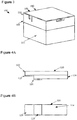
- FIG. 1 shows an example ultrasonic transducer according to an implementation of the disclosed subject matter.
- the ultrasonic transducer 100 includes a substrate 160, PCB 165, and membrane 190.
- the substrate 160 may be any suitable material, such as, for example, a non-conductive layer of a PCB such as FR-4, or a metal, such as aluminum, which may be more rigid than FR-4.
- the substrate 160 may be in any suitable shape and of any suitable thickness.
- the substrate 160 includes a main cavity 130, a secondary cavity 140, a channel 150, and an electromechanically active device 120.
- the substrate 160 may further include trenches 142 and 152.
- the substrate 160 may include any number of fiducials, which may be, for example, predrilled.
- the main cavity 130 is a cavity in the substrate 160, formed through any suitable additive or subtractive processes, and may be any suitable shape and any suitable depth.
- the main cavity 130 may be circular with a radius of between 1.0 mm and 1.5 mm, and may have a depth of between 0.5 mm and 0.6 mm.
- the secondary cavity 140 is a cavity in the substrate 160 which overlaps the main cavity 130, and may be any suitable shape.
- the secondary cavity 140 may be a semi-circular cavity.
- the secondary cavity 140 is of less depth than the main cavity 130, such as, for example, between 0.4 mm and 0.5 mm, forming a first step at its intersection with the main cavity 130.
- the secondary cavity 140 may have a radius of, for example between 0.5 mm and 1.0 mm.
- the secondary cavity 140 may appear circular if created before the main cavity 130, but may appear as crescent shape when created after the main cavity 130, or after the main cavity 130 is created.
- the channel 150 may be a channel of any suitable width, made in any suitable manner, which may run through the centers of the main cavity 130 and the secondary cavity 140.
- the channel 150 may be made using a dicing saw cut of any suitable width through the main cavity 130 and the secondary cavity 140.
- the channel 150 is shallower than the secondary cavity 140, so that the channel forms second step where it overlaps the secondary cavity 140.
- the second step may be in alignment with the first step.
- the channel 150 may run across a number of ultrasonic transducers, such as the ultrasonic transducer 100.
- the ultrasonic transducers may be aligned in an electromechanical transducer array so that a straight line cut from a dicing saw may pass through the centers of all of the main cavities, such as the main cavity 130, and secondary cavities, such as the secondary cavity 140, in a group of aligned ultrasonic transducers.
- the main cavity 130, secondary cavity 140, and channel 150 may be created in the substrate 160 in any suitable order.
- a riser of the first step may be further defined by the trench 142.
- the trench 142 may be created any suitable manner, for example, through a dicing saw cut, and may cross the main cavity 130 and the secondary cavity 140 at their overlap.
- the trench 142 may create a flat riser for the first step.
- a riser of the second step may be further defined by the trench 152.
- the trench 152 may be created in any suitable manner, for example, through a dicing saw cut, and may cross the secondary cavity 140 and the channel 150 at their overlap.
- the trench 152 may create a flat riser for the second step.
- the trenches 142 and 152 may have any suitable width, such as, for example, between 0.1 mm and 0.3 mm
- the first step includes a via 180
- the second step includes a via 175.
- the vias 175 and 180 may be any suitable vias, of any suitable size and shape.
- the vias 175 and 180 are electrically conductive, and may, for example, be filled with an electrically conductive epoxy.
- the vias 175 and 180 descend through the substrate 160 and provide an electrical connection to components of the PCB 165.
- the vias 175 and 180 may be created in the substrate 160 in any suitable manner, such as, for example, through the drilling of the substrate 160.
- the vias 175 and 180 are each covered by an electrode to facilitate electrical connection through the vias 175 and 180.
- the vias 175 and 180 may have a diameter of, for example, 0.2 mm.
- the electromechanically active device 120 may be any suitable electromechanically active device for vibration at ultrasonic frequencies, for example, frequencies over 20,000 Hz.
- the electromechanically active device 120 may be, for example, a piezoelectric unimorph or bimorph which may use piezoceramic material bonded to an electrically inactive substrate.
- the electromechanically active device 120 may be any suitable shape, and may, be for example, a cantilever or flexure.
- the electromechanically active device 120 may include an electrically passive material 122, which may be, for example, stainless steel, aluminum, Invar, Kovar, or silicon/aluminum alloy, bonded to an electrically active material 124, which may be, for example, piezoceramic.
- the electromechanically active device 120 of the ultrasonic transducer 100 may be bonded to the substrate 160 at the first and second steps, with the free end of the electromechanically active device 120 projecting out, and suspended, over the bottom of the main cavity 130.
- the electrically passive material 122 may include an electrode 126
- the electrically active material 124 may include an electrode 128.
- the electrodes 126 and 128 may be bonded to the vias 175 and 180 using a conductive epoxy, which may allow for an electrical connection between the electromechanically active device 120 and the PCB 165 and its components. This may allow for the supply of an electrical current through the PCB 165 to the electromechanically active device 120, causing the electromechanically active device 120 to vibrate at ultrasonic frequencies, for example, through deformation or movement of the electrically active material 124 in response to the electrical current. This may also allow for the supply to the PCB 165 of an electrical current generated through deformation of the electromechanically active device 120 when the electromechanically active device 120 is vibrated by received ultrasonic acoustic waves.
- the top surface of the electromechanically active device 120 may be level with, or slightly below, the top surface of the substrate 160.
- the membrane 190 may be cut to an appropriate size for the ultrasonic transducer 100, or an electromechanical transducer array including the ultrasonic transducer 100.
- the membrane 190 may be slightly larger than the area which the membrane 190 is intended to cover an electromechanical transducer array.
- the membrane 190 may be any suitable light and stiff material for vibrating at ultrasonic frequencies, such as, for example, aluminum shim stock, metal-patterned Kapton, or any other metal-patterned film.
- the membrane 190 may also include suitable patterned structures.
- the ultrasonic transducer 100 may form a transducer cell 195 of an electromechanical transducer array.
- An electromechanical transducer array may include any number of transducer cells, such as the transducer cell 195, arranged in any suitable manner.
- FIG. 2 shows an example ultrasonic transducer according to an implementation of the disclosed subject matter.
- the electromechanically active device 120 may be bonded to the first step and the second step of the substrate 160.
- the top electromechanically active device 120 may be level, or close to level, with the top of the substrate 160, and the tip of the electromechanically active device 120 may project about halfway out over the main cavity 130.
- FIG. 3 shows an example ultrasonic transducer according to an implementation of the disclosed subject matter.
- the membrane 190 may be placed on the ultrasonic transducer 100, and may be bonded to the substrate 160 using any suitable technique.
- the membrane 190 may be bonded to the substrate 160 using epoxy.
- a section of the membrane 190 may cover the ultrasonic transducer 100, and may be bonded to the electromechanically active device 120 near the tip of the electromechanically active device 120.
- the section of the membrane 190 may be bonded to the borders of the transducer cell 195, and may wholly or partially seal the main cavity 130 and secondary cavity 140.
- FIG 4A shows an example electromechanically active device according to an implementation of the disclosed subject matter.
- the electrically passive material 122 may be longer than the electrically active material 124.
- the electrically passive material 122 and the electrically active material 124 may be aligned on one end of the electromechanically active device 120, and the electrically passive material 122 may extend beyond the electrically active material 124 on the other end of the electromechanically active device 120.
- the overhang, or tail, created by the electrically passive material 122 may allow the electromechanically active device 120 to fit into the step structure of the substrate 160, including the first step and the second step.
- the electromechanically active device 120 may be a bimorph or a trimorph, and the tail may be any suitable combination of electrically active materials and electrically passive materials.
- FIG. 4B shows an example electromechanically active device according to an implementation of the disclosed subject matter.
- the underside of the electromechanically active device 120 may include the underside of the electrically active material 124 and its electrode 128.
- the electrode 126 may cover the portion of the underside of the electrically passive material 122 that is not bonded to top of the electrically active material 124.
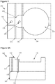
- Figure 5 shows an example ultrasonic transducer according to an implementation of the disclosed subject matter.
- the trench 142 may be created at the edge of the main cavity 130, at the location where the main cavity 130 meets the secondary cavity 140.
- the trench 142 may have the same depth as the main cavity 130, and may, for example, flatten out the circular edge of the main cavity 130, creating a flat riser for the first step from the main cavity 130 to the secondary cavity 140.
- the trench 152 may be created at the edge of the secondary cavity 140, at the location where the secondary cavity 140 meets the channel 150.
- the trench 152 may have the same depth as the secondary cavity 140, and may, for example, flatten out the circular edge of the secondary cavity 140, creating a flat riser for the second step from the secondary cavity 140 to the channel 150.
- Figure 6A shows an example cross-sectional view of an ultrasonic transducer according to an implementation of the disclosed subject matter.
- the vias 175 and 180 descend through the depth of the substrate 160 to the PCB 165. This allows the vias 175 and 180 to carry electricity from the PCB 165, and components thereof, to the tread of the first step, in the secondary cavity 140, and the tread of the second step, in the channel 150.
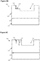
- Figure 6B shows an example cross-sectional view of an ultrasonic transducer according to an implementation of the disclosed subject matter.
- the substrate 160 may be highest on either side of the channel 150.
- the trench 152 may be cut through the width of the substrate 160.
- Figure 6C shows an example cross-sectional view of an ultrasonic transducer according to an implementation of the disclosed subject matter.
- the substrate 160 may be highest on either of the secondary cavity 140.
- the trench 142 may be cut through the width of the substrate 160.
- FIG. 7 shows an example cross-sectional view of an ultrasonic transducer according to an implementation of the disclosed subject matter.
- the electromechanically active device 120 may be bonded to the substrate 160 in any suitable manner.
- the electromechanically active device 120 may be aligned in the substrate 160 so that a free end of the electromechanically active device 120 projects out and is suspended over the main cavity 130 approximately halfway to the far side of the main cavity 130 from where the first step and second step are located.
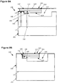
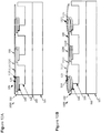
- FIG 8A shows an example cross-sectional view of an ultrasonic transducer according to an implementation of the disclosed subject matter.
- the electrode 128 is bonded to the tread of the first step, in the secondary cavity 140.
- the electrode 128 makes electrical contact with the via 180, for example, through a conductive epoxy, electrically connecting the electrode 128, and the electrically active material 124, to the PCB 165 and its components.
- the electrode 126 is bonded to the tread of the second step, in the channel 150.
- the electrode 126 makes electrical contact with the via 175, for example, through a conductive epoxy, electrically connecting the electrode 126, and the electrically passive material 122, to the PCB 165 and its components.
- the electrical connections to the PCB 165 through the vias 175 and 180 allow the electromechanically active device 120 to be driven by electrical signals supplied through the PCB 165, or to supply an electrical signal to the PCB 165 when the electromechanically active device 120 is driven by received ultrasonic acoustic waves.
- a power source and/or power storage may be part of, or connected to, the PCB 165, and may supply electricity that may be used to drive the electromechanically active device 120 through the vias 175 and 180, causing the electromechanically active device 120 to vibrate at ultrasonic frequencies, or to store electricity generated by the electromechanically active device 120 when the electromechanically active device 120 is caused to vibrate by ultrasonic acoustic waves.
- FIG. 8B shows an example cross-sectional view of an ultrasonic transducer according to an implementation of the disclosed subject matter.
- the top of the electromechanically active device 120 may be at, or near, level with the top of the substrate 160 of the ultrasonic transducer 100.
- Figure 8C shows an example cross-sectional view of an ultrasonic transducer according to an implementation of the disclosed subject matter.
- the free end of the electromechanically active device 120 extends out over the main cavity 130, and has room to move downwards within the main cavity 130.
- FIG. 9A shows an example cross-sectional view of an ultrasonic transducer according to an implementation of the disclosed subject matter.
- the membrane 190 is bonded to the ultrasonic transducer 100.
- the membrane 190 may be bonded to the tip of the electromechanically active device 120 by bonding structure 910.
- the bonding structure 910 may hold the membrane 190 above the top surface of the electromechanically active device 120.
- the bonding structure 910 may be, for example, a dot of epoxy which may have any suitable thickness, and may act as a standoff between the membrane 190 and the tip of the electromechanically active device 120 while bonding them together.
- the bonding structure 910 may also be a small standoff made of any suitable material, such as a metal, ceramic, or plastic, and may be bonded to both the electromechanically active device 120 and the membrane 190.
- the tip of the electromechanically active device 120 may be slightly off the center of the section of the membrane 190 that covers the ultrasonic transducer 100.
- FIG. 9B shows an example cross-sectional view of an ultrasonic transducer according to an implementation of the disclosed subject matter.
- the membrane 190 may be bonded to the ultrasonic transducer 100 so that the edges of the section of the membrane 190 that covers the ultrasonic transducer 100 are on the edges of the transducer cell 195 for the ultrasonic transducer 100.
- the membrane 190 may cover the main cavity 130, the secondary cavity 140, and the channel 150.
- Figure 9C shows an example cross-sectional view of an ultrasonic transducer according to an implementation of the disclosed subject matter.
- the free end of the electromechanically active device 120 extends out over the main cavity 130, and has room to move downwards within the main cavity 130, pulling the membrane 190 into the main cavity 130.
- FIG 10 shows an example electromechanical transducer array according to an implementation of the disclosed subject matter.
- An electromechanical transducer array 1000 may include any number of ultrasonic transducers, such as the ultrasonic transducer 100.
- the ultrasonic transducers may be arranged in any suitable manner, such as, for example, in a grid pattern.
- the trenches 152 and 142 may cross multiple ultrasonic transducers.
- the ultrasonic transducers of the electromechanical transducer array 1000 may share the same substrate 160, which may be a continuous piece of substrate material, such as, for example, FR-4, or a metal such as aluminum which may provide more rigidity to the electromechanical transducer array 1000 than FR-4.
- separate pieces of substrate material may be used, for example, with each piece of substrate material having one ultrasonic transducer, or multiple ultrasonic transducers, creating physically separate ultrasonic transducers, or separate groups of ultrasonic transducers.
- the separate, or separate groups of, ultrasonic transducers may be attached to the same PCB 165.
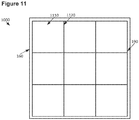
- FIG 11 shows an example electromechanical transducer array according to an implementation of the disclosed subject matter.
- the membrane 190 may have several membrane sections, such as the membrane section 1110, which may be defined by membrane borders 1120 formed where the membrane 190 is bonded to the substrate 160 of the electromechanical transducer array 1000.
- the membrane borders 1120 may be formed by lines of epoxy that bond the membrane 190 to the substrate 160.
- Each membrane section, such as the membrane section 1100, of the membrane 190 may cover an ultrasonic transducer, such as the ultrasonic transducer 100, of the electromechanical transducer array 1000.
- the membrane borders 1120 may form the outlines of the transducer cells, such as the transducer cell 195, for each ultrasonic transducer.
- FIG 12A shows an example ultrasonic device according to an implementation of the disclosed subject matter.
- the membrane section 1110 of the membrane 190 may cover the ultrasonic transducer 100 of the electromechanical transducer array 1000.
- the membrane borders 1120 which may be, for example, bond lines formed by cured epoxy, may mechanically isolate membrane sections from each other through attachment of the membrane 190 to the substrate 160.
- the membrane sections 1110 may be held above the top surface of the electromechanically active device 120 by the bonding structure 910.
- the bonding structure 910 may bond the tip of the electromechanically active device 120 slightly off the center of the membrane section 1110.
- FIG 12B shows an example ultrasonic device according to an implementation of the disclosed subject matter.
- the membrane sections, such as membrane sections 1110, 1215, and 1290, of the membrane 190 may be mechanically isolated from each other by the bond between the membrane 190 and the substrate 160, for example, at the membrane borders 1120.
- the membrane section 1110 may be pushed upwards at the location of the bonding structure 910. Because the bonding structure 910 may be slightly off center, the membrane section 1110 may be pushed upwards at its center by the bonding structure 910 and the flexed tip of the electromechanically active device 120.
- the bond at the membrane borders 1120 may mechanically isolate the membrane section 1110 from neighboring membrane section 1290, so that movement of the membrane section 1110 due to movement of the electromechanically active device 120 does not cause any movement or disturbance of the membrane section 1290.
- the electromechanically active device 1225 may be activated and flex upward, pushing up the membrane section 1215.
- the neighboring membrane section 1290 may be mechanically isolated from the membrane section 1215 by the bond between the membrane 190 and the substrate 160 at the membrane borders 1120.
- the ultrasonic transducers such as the ultrasonic transducer 100, of an electromechanical transducer array 1000 may thus generate acoustic waves at ultrasonic frequencies independent of neighboring ultrasonic transducers, through independent movement of the membrane sections, such as the membrane sections 1100, 1215, and 1290.
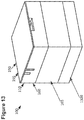
- FIG. 13 shows an example ultrasonic transducer according to an implementation of the disclosed subject matter.
- a rigid mass 1300 may be added to the ultrasonic transducer 100.
- the rigid mass 1300 may be bonded to the back of the PCB 165 of the ultrasonic transducer 100 in any suitable manner, for example, using any suitable adhesive, bonding agent, or epoxy.
- the rigid mass 1300 may be, for example, a sheet or plate of aluminum, copper, silicon/aluminum alloy, or silicon, and may be used to enhance the rigidity of the ultrasonic transducer 100. This may reduce unwanted vibrations of the ultrasonic transducer 100 when the electromechanically active device 120 is vibrating, and moving the membrane 190, at ultrasonic frequencies.
- the rigid mass 1300 may be added to the ultrasonic transducer 100 when the substrate 160 is a less rigid material, such as FR-4.
- the rigid mass 1300 may also be added to the ultrasonic device 100 when the substrate 160 is a more rigid material, such as aluminum, to further enhance the rigidity of the ultrasonic transducer 100.
- the rigid mass 1300 may be bonded to the back of the substrate 160 instead of to the PCB 165, or an additional rigid mass may be bonded to the back of the substrate 160.
- FIG 14 shows an example electromechanical transducer array according to an implementation of the disclosed subject matter.
- the rigid mass 1300 may be bonded to the back of the PCB 165 of the electromechanical transducer array 1000, and the ultrasonic transducers of the electromechanical transducer array 1000.
- the rigid mass 1300 may reduce unwanted vibrations of the ultrasonic transducers of the electromechanical transducer array 1000.
- the rigid mass 1300 may be bonded to the back of the substrate 160 instead of to the PCB 165, or an additional rigid mass may be bonded to the back of the substrate 160.
Description
- Electromechanically active devices may be used in a variety of applications. For example, electromechanically active devices may be used in transducers, sensors, and, actuators. In some uses, the electromechanically active device may be used to generate soundwaves, including ultrasonic soundwaves through vibration of the electromechanically active device. A membrane, or diaphragm, may be added to the electromechanically active device to provide additional surface area to move a medium, such as the air, with the vibrations of the electromechanically active device.
- Document
WO 2014/143942 A2 discloses an ultrasonic transducer having a membrane and a container having a base wall and at least one wall element. An array of the ultrasonic transducers can be controlled to produce a steerable beam. - Document
WO 2014/164018 A1 discloses a portable electronic device using a tactile vibrator for providing tactile feedback to the user. The housing of the electronic device may be made of piezoelectric ceramic material, or a piezoelectric element may be may be coupled to the housing to cause the housing to vibrate. - Document
US 6,445,108 B1 discloses a piezoelectric acoustic component including a diaphragm having a rectangular piezoelectric plate, an insulating cap, and a plate shaped substrate, wherein an acoustic space is provided between the diaphragm and the upper wall of the insulating cap. - The present invention provides an ultrasonic transducer as defined in the independent claim 1.
- Advantageous aspects of the invention are defined in the dependent claims. Moreover, it is to be understood that both the foregoing summary and the following detailed description are examples and are intended to provide further explanation without limiting the scope of the claims.
- The accompanying drawings, which are included to provide a further understanding of the disclosed subject matter, are incorporated in and constitute a part of this specification. The drawings also illustrate embodiments of the disclosed subject matter and together with the detailed description serve to explain the principles of embodiments of the disclosed subject matter. No attempt is made to show structural details in more detail than may be necessary for a fundamental understanding of the disclosed subject matter and various ways in which it may be practiced.
-
Figure 1 shows an example ultrasonic transducer according to an implementation of the disclosed subject matter. -
Figure 2 shows an example ultrasonic transducer according to an implementation of the disclosed subject matter. -
Figure 3 shows an example ultrasonic transducer according to an implementation of the disclosed subject matter. -
Figure 4A shows an example electromechanically active device according to an implementation of the disclosed subject matter. -
Figure 4B shows an example electromechanically active device according to an implementation of the disclosed subject matter. -
Figure 5 shows an example ultrasonic transducer according to an implementation of the disclosed subject matter. -
Figure 6A shows an example cross-sectional view of an ultrasonic transducer according to an implementation of the disclosed subject matter. -
Figure 6B shows an example cross-sectional view of an ultrasonic transducer according to an implementation of the disclosed subject matter. -
Figure 6C shows an example cross-sectional view of an ultrasonic transducer according to an implementation of the disclosed subject matter. -
Figure 7 shows an example cross-sectional view of an ultrasonic transducer according to an implementation of the disclosed subject matter. -
Figure 8A shows an example cross-sectional view of an ultrasonic transducer according to an implementation of the disclosed subject matter. -
Figure 8B shows an example cross-sectional view of an ultrasonic transducer according to an implementation of the disclosed subject matter. -
Figure 8C shows an example cross-sectional view of an ultrasonic transducer according to an implementation of the disclosed subject matter. -
Figure 9A shows an example cross-sectional view of an ultrasonic transducer according to an implementation of the disclosed subject matter. -
Figure 9B shows an example cross-sectional view of an ultrasonic transducer according to an implementation of the disclosed subject matter. -
Figure 9C shows an example cross-sectional view of an ultrasonic transducer according to an implementation of the disclosed subject matter. -
Figure 10 shows an example electromechanical transducer array according to an implementation of the disclosed subject matter. -
Figure 11 shows an example electromechanical transducer array according to an implementation of the disclosed subject matter. -
Figure 12A shows an example ultrasonic device according to an implementation of the disclosed subject matter. -
Figure 12B shows an example ultrasonic device according to an implementation of the disclosed subject matter. -
Figure 13 shows an example ultrasonic transducer according to an implementation of the disclosed subject matter. -
Figure 14 shows an example electromechanical transducer array according to an implementation of the disclosed subject matter. - The ultrasonic transducer includes an electromechanically active device, such as a cantilever or flexure, attached to the wall of a cavity in a substrate. The electromechanically active device may be made from a laminate material, and includes electrodes. The substrate includes a step structure with vias which are in contact with the electrodes of the electromechanically active device. The ultrasonic transducer includes a membrane which covers a top surface of the ultrasonic transducer, and is attached to the electromechanically active device. The substrate of the ultrasonic may be a layer of a printed circuit board (PCB), or may be a rigid material such as copper or aluminum. A rigid material may be attached to the bottom of the ultrasonic transducer. Multiple ultrasonic transducers may be created using the same piece of substrate, forming an electromechanical transducer array.
- The ultrasonic transducer includes a substrate. The substrate may be any suitable material, and may be, for example, the top layer of a PCB with any suitable number of layers. The top layer of the PCB may be a non-conductive material such as, for example, FR-4. The substrate may be in any suitable shape, and the surface of the substrate may be flat, or may be curved or textured in any suitable manner. The substrate may include recessed features. The substrate may define the structure of the ultrasonic transducer, provide electrical contact, rigidly secure the electromechanically active device and allow a variation of the rigidity with which the electromechanically active device is secured. The substrate may form a base for an electromechanical transducer array, which may include a number of ultrasonic transducers. Recessed cavities in the substrate may be used to provide positioning and positive alignment during construction of an electromechanical transducer array including a number of ultrasonic transducers. The substrate may be made and structured in any suitable manner, for example, using PCB manufacturing techniques. For example, the recessed cavities may be created with mill holes. Layer lamination, dicing saw cuts and epoxy filled vias may be used to create the structure of the substrate. The structure of the substrate may also be created using negative mold casting or an ordering of subtractive processes. The substrate may be the top, non-conductive layer of a PCB, which may allow for the breakout of the ultrasonic transducers of the electromechanical transducer array through the conductive layers of the PCB and connecting vias. The use of PCB as a substrate may also allow for electrical control circuitry for the electromechanical transducer array to be placed onto the back-side of the PCB of the electromechanical transducer array. Other materials such as ceramics, plastics, or metals, including, for example, aluminum, copper, silicon/aluminum alloy, and silicon, which may be coated or anodized to be non-conductive, may also be used as or in the substrate, and may offer differing levels of mechanical support for the cantilevers in the elements of the electromechanical transducer array. For example, the substrate may be aluminum, and may be attached to the top layer of a PCB in any suitable manner.
- The substrate may be designed, for example, using sub-dicing with a dicing saw, which may disrupt lateral and parasitic modes of oscillation among electromechanically active devices of the electromechanical transducer array. The substrate may be made of materials of any suitable stiffness. The stiffness of the materials of the substrate may determine the rigidity of the base to which the electromechanically active device may be bonded. The substrate may be non-planar, and may also be flexible. The substrate may be anisotropic. The sub-diced sections of the substrate may be left empty, or may be filled with another material, such as an absorbing material such as silicone rubber.
- The cavity of the ultrasonic transducer may be any suitable shape and have any suitable depth. For example, the cavity may be circular. The electromechanically active device may be attached to the wall of the cavity in any suitable manner. A step structure is created on an edge of the cavity, and the electromechanically active device is bonded to the step structure using any suitable adhesive, such as, for example, conductive epoxy. The step structure is created by creating an additional cavity in the substrate. The additional cavity partially overlaps the cavity, and is shallower than the cavity. This creates a step at the location where the additional cavity overlaps the cavity, and the additional cavity may appear as crescent shape in the substrate. A second step is created by creating a channel of any suitable shape in the substrate, partially overlapping the additional cavity. The channel is shallower than the additional cavity, creating the second step at the location of the overlap. The step and the second step may be aligned. The length of the tread, or shelf, or each step in the step structure to which the electromechanically active device may be bonded may determine the resonant free-length of the electromechanically active device. The recessed surfaces of the substrate, such as the cavities, may be designed to permit bonds of varying and controllable strength to the electromechanically active device, which may affect the performance of the electromechanically active device and the output of the ultrasonic transducer. Altering the length of the area to which the electromechanically active device may be bonded may affect the frequency and amplitude, or velocity of output, or amplitude, of the ultrasonic transducer. The structure of the substrate may provide clearance for the electromechanically active device to move both up and down over any suitable distance.
- The step structure of the substrate may be further defined by trenches, which may be created to any suitable depth, and may cross through each overlap location. For example, a trench having the same depth as the cavity may be created at the overlap of the cavity and the additional cavity, and a trench having the same depth as the additional cavity may be created at the overlap of the channel and the additional cavity. The trenches may, for example, be used to create a flat front wall, or riser, for the step and the second step. The cavity, additional cavity, channel, and trenches may be created in the substrate of the ultrasonic transducer in any suitable manner, including through subtractive processes, such as drilling, milling, and dicing saw cuts, and through additive processes.
- The substrate includes at least two vias. The vias are patterned in pairs offset from one another. One via of a pair of vias makes electrical contact with an electrode for an electrically passive layer, such as a conductive metal, of an electromechanically active device. The electrode contacts the via on the tread of a step of the step structure of the substrate. The other via of the pair of vias makes contact with an electrode on an electrically active material, such as a piezoceramic, of the electromechanically active device. The electrode contacts the other via on the tread of the other step of the step structure. The electrodes may be, for example, thin-film electrodes. The vias may be filled with a conductive epoxy so that when a dicing saw is used to create the recesses, such as the step structure, to accommodate the electromechanically active device, there may be reduced risk of losing conductivity at the electrical contact points of the vias.
- In an example not forming part of the invention, the substrate may include any number of vias for a single electromechanically active device. The vias may be any suitable combination of blind vias, buried vias, and through vias. Other numbers of vias, and different types of connections with two vias, may be used to establish electrical connectivity with the ultrasonic transducers of an electromechanical transducer array. For example, with one via, the connection to an ultrasonic transducer of an electromechanical transducer array may be hot connection to an electromechanically active device, with a common ground. With two vias, the connections to an ultrasonic transducer may be a hot connection and a ground connection, or a positive connection and a negative connection. With three vias, the connections to an ultrasonic transducer may be two hot connections and one ground connection, two ground connection and one hot connection, or a positive connection, a negative connection, and a ground connection. The structure of the substrate may allow for electrical isolation between the components of the electromechanical transducer array.
- The ultrasonic transducer includes an electromechanically active device attached to the substrate. The electromechanically active device may be a cantilever or flexure, and may be, for example, a piezoceramic unimorph, bimorph, or trimorph. The electromechanically active device may include an electrically active material, such as piezoelectric material or piezoceramic, electrostrictive material, or ferroelectric material, which may able to transform electrical excitation into a high-frequency vibration to produce ultrasonic acoustic emissions. The geometry of an electromechanically active device may affect the frequency, velocity, force, displacement, capacitance, bandwidth, and efficiency of electromechanical energy conversion produced by the electromechanically active device when driven to output ultrasound and the voltage and current generated by the electromechanically active device and efficiency of electromechanical energy conversion when driven by received ultrasound. The electromechanically active device may have a rectangular profile, or may have a profile based on any other suitable geometry, such as, for example, a trapezoidal geometry. The geometry of the electromechanically active device may be selected, for example, to tune the balance and other various characteristics of the electromechanically active device. The electromechanically active device may be made using single layer of piezoelectric material laminated onto a single passive substrate material. The electromechanically active device may also be made with a single piezoelectric layer and multiple passive layers; two piezoelectric layers operating anti-phase, or two piezoelectric layers, operating anti-phase and combined with one or more electrically passive materials. Different layers of the electromechanically active device may have different shapes. For example, in a unimorph, a piezoelectric material may be shaped differently from a passive substrate material to which the piezoelectric material is bonded. The piezoelectric material, for example, piezoceramic, used in the electromechanically active device may be poled in any suitable manner, with polarization in any suitable direction.
- The electromechanically active device may be any suitable size for use in an ultrasonic transducer, and for vibrating at ultrasonic frequencies. For example, the electromechanically active device may have a width of between 0.5 mm and 1.5 mm, a height of between 0.4 mm and 0.5 mm, and a length of between 2.0 and 3.0 mm, though different layers of the electromechanically active device may have different lengths to allow bonding with the stair structure of the substrate. The electromechanically active device may be made in any suitable manner, such as, for example, by cutting rectangular geometries from a larger laminate material. The laminate material may be made from, for example, an electrically active material, such a piezoceramic, bonded to an electrically inactive substrate, such as, for example, metals such as aluminum, Invar, Kovar, silicon/aluminum alloys, stainless steel, and brass, using any suitable bonding techniques and materials. The materials used may be non-optimal for the performance of an individual electromechanically active device. For example, materials may be selected for consistent performance across a larger number of electromechanically active device or for ease of manufacture. An electromechanically active device may include a tail which may be used in securing the electromechanically active device onto the substrate of the ultrasonic transducer, and may facilitate electrical contact, for example, with a via in the substrate. The tail of the electromechanically active device may protrude beyond the substrate of the ultrasonic transducer. The tail may be structured through a subtractive process, for example, with ceramic material being cut away from the electromechanically active device. An additive process may also be used, for, example, with the piezoelectric layer of a laminate material first structured to the desired geometry and then bonded onto the passive substrate material with a pitch approximately equal to the desired length of the electromechanically active device, after which the rectangular electromechanically active device may be cut out of the bonded materials.
- The electromechanically active device may be oriented in the cavity at any suitable angle. For example, the electromechanically active device may oriented along a diameter of a circular cavity, and may reach approximately halfway across the cavity. The top surface of the electromechanically active device, which may be, for example, a passive material of a unimorph or an active material of a bimorph, may be level, or near-level, with the top of the cavity. The electromechanically active device may be attached to the substrate of an ultrasonic transducer in any suitable manner. For example, any of the underside or both sides of the electromechanically active device may be bonded to the substrate, for example, at the step structure of the substrate. The bonds used to secure the electromechanically active device to the substrate may be any suitable combination of organic or inorganic bonds, using any suitable conductive and non-conductive bonding materials, such as, for example, epoxies or solders. The area of contact between the electromechanically active device and the substrate may be any suitable size and shape. In some implementations, an ultrasonic transducer may include more than one electromechanically active device within a cavity. The ultrasonic device may include any number of ultrasonic transducers in any suitable arrangement.
- The electromechanically active device may be bonded in a suitable position on the substrate, with the passive or active layers of the electromechanically active device facing down depending on whether the electromechanically active device is a unimorph, bimorph, trimorph, or has some other structure. The bond may use any suitable bonding agent, solder, or epoxy. For example, conductive adhesive film may be applied to the areas of the electromechanically active device to be bonded to the substrate. The electromechanically active device may be pressed into the substrate and drawn back so that a back wall of the electromechanically active device may be pulled flush against the step structure of the substrate. The electromechanically active device may be placed onto the substrate by, for example, a pick and place machine using a UV release tape to pick up the electromechanically active device. The conductive adhesive film may be cured, after which the electromechanically active device may be separated from the UV release type by exposure to the release agent, for example, UV light. The area to which an electromechanically active device may be bonded may extend outside a single ultrasonic transducer and into a neighboring ultrasonic transducer in an electromechanical transducer array, making use of otherwise unused space on the opposite side of each ultrasonic transducer. This may result in a small additional space at one edge of the electromechanical transducer array.
- A membrane is bonded to the ultrasonic transducer to create an ultrasonic device with a membrane. A membrane may be attached with adhesive in a manner that may define the outline of a number of cells of the electromechanical transducer array which the membrane will cover, where each cell may include an ultrasonic transducer. The electromechanically active device of a covered ultrasonic transducer is bonded to the membrane, for example, at or near the tip of the electromechanically active device. A membrane may be multiple separate pieces of material, each of which may cover one ultrasonic transducer, or multiple ultrasonic transducers, or may be single piece of material which may cover all of the ultrasonic transducers of the electromechanical transducer array. A membrane may be aligned with one or more ultrasonic transducers and pressed into the substrate to form a covering layer. A membrane may act to acoustically couple the motion of cantilevers to the air, as the motion of cantilevers may cause the membrane to move. A membrane may be attached to the substrate in any other suitable manner, such as, for example, being melted or welded to, including being ultrasonically welded, laser welded, or electron beam welded to, or mechanically attached or pinned to, the substrate. The membrane may be bonded to the substrate, for example, using any suitable epoxy applied in any suitable manner.
- The membrane may be any suitable material or composite material structure, which may be of any suitable stiffness and weight, for vibrating at ultrasonic frequencies. For example, the membrane may be both stiff and light. For example, the membrane may be aluminum shim stock, metal-patterned Kapton, or any other metal-pattern film. The membrane may be impedance matched with the air to allow for more efficient air-coupling of the ultrasonic transducers. The membrane may include additional structures, such as, for example, ring structures located on the membrane where the membrane will contact the tips of the electromechanically active devices.
- The membrane may be attached to an electromechanical transducer array along bond lines, which may be, for example, cured epoxy. The bond lines may divide the electromechanical transducer array into ultrasonic transducer cells of any suitable shape, such as squares. The membrane may also be bonded to the tips of the free end of each electromechanically active device of the electromechanical transducer array. This may result in each ultrasonic transducer being covered with a section of the membrane that is bonded to the substrate around the ultrasonic transducer and also bonded to the tip of the free end of the ultrasonic transducer's electromechanically active device. The tip of the free end of the electromechanically active device may be slightly off being aligned with the center of the section of the membrane. This may allow the section of the membrane to be pushed outward by the electromechanically active device so that the highest point of the section of the membrane is at the center of the section of the membrane. Each section of the membrane may be able to move independently of any other section of the membrane, though the membrane may remain a single piece of material. The bond lines formed by the cured epoxy may mechanically isolate the sections of the membrane from each other. The movement of one section of the membrane may not be transmitted across a bond line, where the membrane is bonded to the substrate, to another section of the membrane.
- An electromechanical transducer array may include any number of ultrasonic transducers. The ultrasonic transducers may share a common piece of material as a substrate, or may use any suitable number of separate pieces of material, for example, with each ultrasonic transducer having its own separate piece of substrate material. The ultrasonic transducers of an electromechanical transducer array may be divided into cells. Each cell may include a single ultrasonic transducer covered by a membrane or membrane section, or may include multiple ultrasonic transducers. The cells of may be any suitable shape, in any suitable pattern. For example, cells may be squares, rectangles, circles, hexagons, irregular polygons and have one or more curved boundaries. Cells may be arranged in any suitable pattern. For example, cells may be arranged in a grid pattern, circular pattern, or hexagonal pattern.
- The substrate of an electromechanical transducer array may be a top layer of a PCB, or may be attached to the top layer of a PCB. ASICs and other electronics may be mounted on, or in, the electromechanical transducer array, for example, on or in the substrate or other layers of the PCB to which the substrate is attached. Components for one or more resistor-inductor-capacitor (RLC) circuits may also be embedded in the substrate. Batteries of any suitable size, and capacitors of any suitable capacity and with any suitable electrical properties, including supercaps, may be included in the electromechanical transducer array. The materials of the substrate may lend rigidity, for example, to a case or other housing that may contain or include an electromechanical transducer array, and may protect components of the electromechanical transducer array or other components. A layer of material may be attached to the bottom of the electromechanical transducer array to provide enhanced rigidity to the electromechanical transducer array and the ultrasonic transducers. For example, an aluminum plate may be bonded, in any suitable manner, to the back of the bottom of the electromechanical transducer array.
- The substrate may be able to support a lateral mode caused by the electromechanically active devices, or may be able to transfer motion from one ultrasonic transducer to its neighbor. Any suitable techniques may be used in the design and manufacture of the substrate to minimize crosstalk and lateral modes. For example, the substrate may be sub-diced, which may include cutting a pattern to a certain depth into the rear side of the substrate with a saw. This may ensure that there is no path for any laterally propagating wave. Trenches created by sub-dicing may be filled with a damping or absorbing material such as silicone rubber to lessen transverse waves. Electrically insulating layers may be used, for example, in the trenches created by sub-dicing, for electrical cross-talk isolation of the various conductive components of electromechanical transducer array. Electrically conductive barriers may be used as shielding planes, for example, between cells of the electromechanical transducer array.
- An electromechanical transducer array may be designed to accommodate the thermal expansion of the various materials it is made of, reducing or eliminating the effects of the thermal expansion on the performance of the electromechanical transducer array. An electromechanical transducer array may be designed to be robust to shocks and impacts.
- In some implementations, more than one membrane may be bonded to an electromechanical transducer array. For example, multiple separate membranes of the same material, or different materials may be used to cover the ultrasonic transducers of an electromechanical transducer array. Different materials may be used, for example, to allow different sections of the ultrasonic device to have different operating characteristics.
-
Figure 1 shows an example ultrasonic transducer according to an implementation of the disclosed subject matter. Theultrasonic transducer 100 includes asubstrate 160,PCB 165, andmembrane 190. Thesubstrate 160 may be any suitable material, such as, for example, a non-conductive layer of a PCB such as FR-4, or a metal, such as aluminum, which may be more rigid than FR-4. Thesubstrate 160 may be in any suitable shape and of any suitable thickness. Thesubstrate 160 includes amain cavity 130, asecondary cavity 140, achannel 150, and an electromechanicallyactive device 120. Thesubstrate 160 may further includetrenches substrate 160 may include any number of fiducials, which may be, for example, predrilled. Themain cavity 130 is a cavity in thesubstrate 160, formed through any suitable additive or subtractive processes, and may be any suitable shape and any suitable depth. For example, themain cavity 130 may be circular with a radius of between 1.0 mm and 1.5 mm, and may have a depth of between 0.5 mm and 0.6 mm. Thesecondary cavity 140 is a cavity in thesubstrate 160 which overlaps themain cavity 130, and may be any suitable shape. For example, thesecondary cavity 140 may be a semi-circular cavity. Thesecondary cavity 140 is of less depth than themain cavity 130, such as, for example, between 0.4 mm and 0.5 mm, forming a first step at its intersection with themain cavity 130. Thesecondary cavity 140 may have a radius of, for example between 0.5 mm and 1.0 mm. Thesecondary cavity 140 may appear circular if created before themain cavity 130, but may appear as crescent shape when created after themain cavity 130, or after themain cavity 130 is created. Thechannel 150 may be a channel of any suitable width, made in any suitable manner, which may run through the centers of themain cavity 130 and thesecondary cavity 140. For example, thechannel 150 may be made using a dicing saw cut of any suitable width through themain cavity 130 and thesecondary cavity 140. Thechannel 150 is shallower than thesecondary cavity 140, so that the channel forms second step where it overlaps thesecondary cavity 140. The second step may be in alignment with the first step. Thechannel 150 may run across a number of ultrasonic transducers, such as theultrasonic transducer 100. For example, the ultrasonic transducers may be aligned in an electromechanical transducer array so that a straight line cut from a dicing saw may pass through the centers of all of the main cavities, such as themain cavity 130, and secondary cavities, such as thesecondary cavity 140, in a group of aligned ultrasonic transducers. Themain cavity 130,secondary cavity 140, andchannel 150 may be created in thesubstrate 160 in any suitable order. - A riser of the first step may be further defined by the
trench 142. Thetrench 142 may be created any suitable manner, for example, through a dicing saw cut, and may cross themain cavity 130 and thesecondary cavity 140 at their overlap. Thetrench 142 may create a flat riser for the first step. A riser of the second step may be further defined by thetrench 152. Thetrench 152 may be created in any suitable manner, for example, through a dicing saw cut, and may cross thesecondary cavity 140 and thechannel 150 at their overlap. Thetrench 152 may create a flat riser for the second step. Thetrenches - The first step includes a via 180, and the second step includes a via 175. The
vias vias vias substrate 160 and provide an electrical connection to components of thePCB 165. Thevias substrate 160 in any suitable manner, such as, for example, through the drilling of thesubstrate 160. Thevias vias vias - The electromechanically
active device 120 may be any suitable electromechanically active device for vibration at ultrasonic frequencies, for example, frequencies over 20,000 Hz. The electromechanicallyactive device 120 may be, for example, a piezoelectric unimorph or bimorph which may use piezoceramic material bonded to an electrically inactive substrate. The electromechanicallyactive device 120 may be any suitable shape, and may, be for example, a cantilever or flexure. For example, the electromechanicallyactive device 120 may include an electricallypassive material 122, which may be, for example, stainless steel, aluminum, Invar, Kovar, or silicon/aluminum alloy, bonded to an electricallyactive material 124, which may be, for example, piezoceramic. The electromechanicallyactive device 120 of theultrasonic transducer 100 may be bonded to thesubstrate 160 at the first and second steps, with the free end of the electromechanicallyactive device 120 projecting out, and suspended, over the bottom of themain cavity 130. The electricallypassive material 122 may include anelectrode 126, and the electricallyactive material 124 may include anelectrode 128. When the electromechanicallyactive device 120 is bonded to thesubstrate 160 at the first and second step, theelectrode 126 may be aligned with the via 175 on the second step, and theelectrode 128 may be aligned with the via 180 on the first step. Theelectrodes vias active device 120 and thePCB 165 and its components. This may allow for the supply of an electrical current through thePCB 165 to the electromechanicallyactive device 120, causing the electromechanicallyactive device 120 to vibrate at ultrasonic frequencies, for example, through deformation or movement of the electricallyactive material 124 in response to the electrical current. This may also allow for the supply to thePCB 165 of an electrical current generated through deformation of the electromechanicallyactive device 120 when the electromechanicallyactive device 120 is vibrated by received ultrasonic acoustic waves. The top surface of the electromechanicallyactive device 120 may be level with, or slightly below, the top surface of thesubstrate 160. - The
membrane 190 may be cut to an appropriate size for theultrasonic transducer 100, or an electromechanical transducer array including theultrasonic transducer 100. For example, themembrane 190 may be slightly larger than the area which themembrane 190 is intended to cover an electromechanical transducer array. Themembrane 190 may be any suitable light and stiff material for vibrating at ultrasonic frequencies, such as, for example, aluminum shim stock, metal-patterned Kapton, or any other metal-patterned film. Themembrane 190 may also include suitable patterned structures. - The
ultrasonic transducer 100, with a section of themembrane 190, thesubstrate 160, and thePCB 165, may form atransducer cell 195 of an electromechanical transducer array. An electromechanical transducer array may include any number of transducer cells, such as thetransducer cell 195, arranged in any suitable manner. -
Figure 2 shows an example ultrasonic transducer according to an implementation of the disclosed subject matter. The electromechanicallyactive device 120 may be bonded to the first step and the second step of thesubstrate 160. The top electromechanicallyactive device 120 may be level, or close to level, with the top of thesubstrate 160, and the tip of the electromechanicallyactive device 120 may project about halfway out over themain cavity 130. -
Figure 3 shows an example ultrasonic transducer according to an implementation of the disclosed subject matter. Themembrane 190 may be placed on theultrasonic transducer 100, and may be bonded to thesubstrate 160 using any suitable technique. For example, themembrane 190 may be bonded to thesubstrate 160 using epoxy. A section of themembrane 190 may cover theultrasonic transducer 100, and may be bonded to the electromechanicallyactive device 120 near the tip of the electromechanicallyactive device 120. The section of themembrane 190 may be bonded to the borders of thetransducer cell 195, and may wholly or partially seal themain cavity 130 andsecondary cavity 140. -
Figure 4A shows an example electromechanically active device according to an implementation of the disclosed subject matter. The electricallypassive material 122 may be longer than the electricallyactive material 124. The electricallypassive material 122 and the electricallyactive material 124 may be aligned on one end of the electromechanicallyactive device 120, and the electricallypassive material 122 may extend beyond the electricallyactive material 124 on the other end of the electromechanicallyactive device 120. The overhang, or tail, created by the electricallypassive material 122 may allow the electromechanicallyactive device 120 to fit into the step structure of thesubstrate 160, including the first step and the second step. In some implementations, the electromechanicallyactive device 120 may be a bimorph or a trimorph, and the tail may be any suitable combination of electrically active materials and electrically passive materials. -
Figure 4B shows an example electromechanically active device according to an implementation of the disclosed subject matter. The underside of the electromechanicallyactive device 120 may include the underside of the electricallyactive material 124 and itselectrode 128. Theelectrode 126 may cover the portion of the underside of the electricallypassive material 122 that is not bonded to top of the electricallyactive material 124. -
Figure 5 shows an example ultrasonic transducer according to an implementation of the disclosed subject matter. Thetrench 142 may be created at the edge of themain cavity 130, at the location where themain cavity 130 meets thesecondary cavity 140. Thetrench 142 may have the same depth as themain cavity 130, and may, for example, flatten out the circular edge of themain cavity 130, creating a flat riser for the first step from themain cavity 130 to thesecondary cavity 140. Thetrench 152 may be created at the edge of thesecondary cavity 140, at the location where thesecondary cavity 140 meets thechannel 150. Thetrench 152 may have the same depth as thesecondary cavity 140, and may, for example, flatten out the circular edge of thesecondary cavity 140, creating a flat riser for the second step from thesecondary cavity 140 to thechannel 150. -
Figure 6A shows an example cross-sectional view of an ultrasonic transducer according to an implementation of the disclosed subject matter. Thevias substrate 160 to thePCB 165. This allows thevias PCB 165, and components thereof, to the tread of the first step, in thesecondary cavity 140, and the tread of the second step, in thechannel 150. -
Figure 6B shows an example cross-sectional view of an ultrasonic transducer according to an implementation of the disclosed subject matter. Thesubstrate 160 may be highest on either side of thechannel 150. Thetrench 152 may be cut through the width of thesubstrate 160. -
Figure 6C shows an example cross-sectional view of an ultrasonic transducer according to an implementation of the disclosed subject matter. Thesubstrate 160 may be highest on either of thesecondary cavity 140. Thetrench 142 may be cut through the width of thesubstrate 160. -
Figure 7 shows an example cross-sectional view of an ultrasonic transducer according to an implementation of the disclosed subject matter. The electromechanicallyactive device 120 may be bonded to thesubstrate 160 in any suitable manner. The electromechanicallyactive device 120 may be aligned in thesubstrate 160 so that a free end of the electromechanicallyactive device 120 projects out and is suspended over themain cavity 130 approximately halfway to the far side of themain cavity 130 from where the first step and second step are located. -
Figure 8A shows an example cross-sectional view of an ultrasonic transducer according to an implementation of the disclosed subject matter. Theelectrode 128 is bonded to the tread of the first step, in thesecondary cavity 140. Theelectrode 128 makes electrical contact with the via 180, for example, through a conductive epoxy, electrically connecting theelectrode 128, and the electricallyactive material 124, to thePCB 165 and its components. Theelectrode 126 is bonded to the tread of the second step, in thechannel 150. Theelectrode 126 makes electrical contact with the via 175, for example, through a conductive epoxy, electrically connecting theelectrode 126, and the electricallypassive material 122, to thePCB 165 and its components. The electrical connections to thePCB 165 through thevias active device 120 to be driven by electrical signals supplied through thePCB 165, or to supply an electrical signal to thePCB 165 when the electromechanicallyactive device 120 is driven by received ultrasonic acoustic waves. For example, a power source and/or power storage may be part of, or connected to, thePCB 165, and may supply electricity that may be used to drive the electromechanicallyactive device 120 through thevias active device 120 to vibrate at ultrasonic frequencies, or to store electricity generated by the electromechanicallyactive device 120 when the electromechanicallyactive device 120 is caused to vibrate by ultrasonic acoustic waves. -
Figure 8B shows an example cross-sectional view of an ultrasonic transducer according to an implementation of the disclosed subject matter. The top of the electromechanicallyactive device 120 may be at, or near, level with the top of thesubstrate 160 of theultrasonic transducer 100. -
Figure 8C shows an example cross-sectional view of an ultrasonic transducer according to an implementation of the disclosed subject matter. The free end of the electromechanicallyactive device 120 extends out over themain cavity 130, and has room to move downwards within themain cavity 130. -
Figure 9A shows an example cross-sectional view of an ultrasonic transducer according to an implementation of the disclosed subject matter. Themembrane 190 is bonded to theultrasonic transducer 100. For example, themembrane 190 may be bonded to the tip of the electromechanicallyactive device 120 bybonding structure 910. Thebonding structure 910 may hold themembrane 190 above the top surface of the electromechanicallyactive device 120. Thebonding structure 910 may be, for example, a dot of epoxy which may have any suitable thickness, and may act as a standoff between themembrane 190 and the tip of the electromechanicallyactive device 120 while bonding them together. Thebonding structure 910 may also be a small standoff made of any suitable material, such as a metal, ceramic, or plastic, and may be bonded to both the electromechanicallyactive device 120 and themembrane 190. The tip of the electromechanicallyactive device 120 may be slightly off the center of the section of themembrane 190 that covers theultrasonic transducer 100. -
Figure 9B shows an example cross-sectional view of an ultrasonic transducer according to an implementation of the disclosed subject matter. Themembrane 190 may be bonded to theultrasonic transducer 100 so that the edges of the section of themembrane 190 that covers theultrasonic transducer 100 are on the edges of thetransducer cell 195 for theultrasonic transducer 100. Themembrane 190 may cover themain cavity 130, thesecondary cavity 140, and thechannel 150. -
Figure 9C shows an example cross-sectional view of an ultrasonic transducer according to an implementation of the disclosed subject matter. The free end of the electromechanicallyactive device 120 extends out over themain cavity 130, and has room to move downwards within themain cavity 130, pulling themembrane 190 into themain cavity 130. -
Figure 10 shows an example electromechanical transducer array according to an implementation of the disclosed subject matter. Anelectromechanical transducer array 1000 may include any number of ultrasonic transducers, such as theultrasonic transducer 100. The ultrasonic transducers may be arranged in any suitable manner, such as, for example, in a grid pattern. Thetrenches electromechanical transducer array 1000 may share thesame substrate 160, which may be a continuous piece of substrate material, such as, for example, FR-4, or a metal such as aluminum which may provide more rigidity to theelectromechanical transducer array 1000 than FR-4. In some implementations, separate pieces of substrate material may be used, for example, with each piece of substrate material having one ultrasonic transducer, or multiple ultrasonic transducers, creating physically separate ultrasonic transducers, or separate groups of ultrasonic transducers. The separate, or separate groups of, ultrasonic transducers may be attached to thesame PCB 165. -
Figure 11 shows an example electromechanical transducer array according to an implementation of the disclosed subject matter. Themembrane 190 may have several membrane sections, such as themembrane section 1110, which may be defined bymembrane borders 1120 formed where themembrane 190 is bonded to thesubstrate 160 of theelectromechanical transducer array 1000. For example, the membrane borders 1120 may be formed by lines of epoxy that bond themembrane 190 to thesubstrate 160. Each membrane section, such as the membrane section 1100, of themembrane 190 may cover an ultrasonic transducer, such as theultrasonic transducer 100, of theelectromechanical transducer array 1000. The membrane borders 1120 may form the outlines of the transducer cells, such as thetransducer cell 195, for each ultrasonic transducer. -
Figure 12A shows an example ultrasonic device according to an implementation of the disclosed subject matter. Themembrane section 1110 of themembrane 190 may cover theultrasonic transducer 100 of theelectromechanical transducer array 1000. The membrane borders 1120, which may be, for example, bond lines formed by cured epoxy, may mechanically isolate membrane sections from each other through attachment of themembrane 190 to thesubstrate 160. Themembrane sections 1110 may be held above the top surface of the electromechanicallyactive device 120 by thebonding structure 910. Thebonding structure 910 may bond the tip of the electromechanicallyactive device 120 slightly off the center of themembrane section 1110. -
Figure 12B shows an example ultrasonic device according to an implementation of the disclosed subject matter. The membrane sections, such asmembrane sections membrane 190 may be mechanically isolated from each other by the bond between themembrane 190 and thesubstrate 160, for example, at the membrane borders 1120. For example, when the electromechanicallyactive device 120 is activated and flexes upward, themembrane section 1110 may be pushed upwards at the location of thebonding structure 910. Because thebonding structure 910 may be slightly off center, themembrane section 1110 may be pushed upwards at its center by thebonding structure 910 and the flexed tip of the electromechanicallyactive device 120. The bond at the membrane borders 1120 may mechanically isolate themembrane section 1110 from neighboringmembrane section 1290, so that movement of themembrane section 1110 due to movement of the electromechanicallyactive device 120 does not cause any movement or disturbance of themembrane section 1290. Similarly, the electromechanicallyactive device 1225 may be activated and flex upward, pushing up themembrane section 1215. The neighboringmembrane section 1290 may be mechanically isolated from themembrane section 1215 by the bond between themembrane 190 and thesubstrate 160 at the membrane borders 1120. The ultrasonic transducers, such as theultrasonic transducer 100, of anelectromechanical transducer array 1000 may thus generate acoustic waves at ultrasonic frequencies independent of neighboring ultrasonic transducers, through independent movement of the membrane sections, such as themembrane sections -
Figure 13 shows an example ultrasonic transducer according to an implementation of the disclosed subject matter. Arigid mass 1300 may be added to theultrasonic transducer 100. Therigid mass 1300 may be bonded to the back of thePCB 165 of theultrasonic transducer 100 in any suitable manner, for example, using any suitable adhesive, bonding agent, or epoxy. Therigid mass 1300 may be, for example, a sheet or plate of aluminum, copper, silicon/aluminum alloy, or silicon, and may be used to enhance the rigidity of theultrasonic transducer 100. This may reduce unwanted vibrations of theultrasonic transducer 100 when the electromechanicallyactive device 120 is vibrating, and moving themembrane 190, at ultrasonic frequencies. Therigid mass 1300 may be added to theultrasonic transducer 100 when thesubstrate 160 is a less rigid material, such as FR-4. Therigid mass 1300 may also be added to theultrasonic device 100 when thesubstrate 160 is a more rigid material, such as aluminum, to further enhance the rigidity of theultrasonic transducer 100. In some implementations, therigid mass 1300 may be bonded to the back of thesubstrate 160 instead of to thePCB 165, or an additional rigid mass may be bonded to the back of thesubstrate 160. -
Figure 14 shows an example electromechanical transducer array according to an implementation of the disclosed subject matter. Therigid mass 1300 may be bonded to the back of thePCB 165 of theelectromechanical transducer array 1000, and the ultrasonic transducers of theelectromechanical transducer array 1000. Therigid mass 1300 may reduce unwanted vibrations of the ultrasonic transducers of theelectromechanical transducer array 1000. In some implementations, therigid mass 1300 may be bonded to the back of thesubstrate 160 instead of to thePCB 165, or an additional rigid mass may be bonded to the back of thesubstrate 160. - The foregoing description, for purpose of explanation, has been described with reference to specific embodiments. However, the illustrative discussions above are not intended to be exhaustive or to limit embodiments of the disclosed subject matter to the precise forms disclosed. The scope of the present invention is defined by the appended claims.
Claims (9)
- An ultrasonic transducer (100) comprising:a substrate (160) comprising a main cavity (130), a secondary cavity (140), and a channel (150), wherein the main cavity has a greater depth than the secondary cavity, the secondary cavity has a greater depth than the channel, a first step is formedat a location where the main cavity and the secondary cavity overlap, and a second step is formed at a location where the secondary cavity and the channel overlap;an electromechanically active device (120) attached to the substrate (160) at the first step and the second step such that a free end of the electromechanically active device is suspended over a bottom of the main cavity, the electromechanically active device comprising a first electrode (128) and a second electrode (126);a membrane section bonded to the substrate (160) such that the membrane (190) covers the main cavity and the secondary cavity and is bonded to the free end of the electromechanically active device such that vibration of the electromechanically active device at ultrasonic frequencies causes the membrane (190) to vibrate at ultrasonic frequencies;a printed circuit board (PCB) (165) bonded to the substrate at the side opposite of the membrane, the PCB comprising at least one conductive layer;a first via (180) disposed in the first step and a second via (175) disposed in the second step, the first via and the second via descending through the substrate (160) to connect the at least one conductive layer of the PCB; andwherein the first electrode (128) of the electromechanically active device is bonded to the first via and the second electrode (126) of the electromechanically active device is bonded to the second via.
- The ultrasonic transducer (100) of claim 1, wherein the membrane (190) comprises a material impedance matched with the air.
- The ultrasonic transducer (100) of claim 1, wherein the substrate (160) further comprises a first trench (142) creating a flat riser for the first step and a second trench (152) creating a flat riser for the second step.
- The ultrasonic transducer (100) of claim 1, wherein the substrate (160) comprises aluminum.
- The ultrasonic transducer (100) of claim 1, further comprising a rigid mass (1300) bonded to the PCB.
- The ultrasonic transducer (100) of claim 1, wherein the electromechanically active device comprises a piezoceramic unimorph or a piezoceramic bimorph.
- An electromechanical transducer array comprising two ultrasonic transducers (100) according to claim 1, wherein the transducers (100) share the same substrate (160), and wherein a membrane (190) is bonded to the substrate (160), the membrane comprising two membrane sections (1100) of the two ultrasonic transducers.
- The electromechanical transducer array of claim 7, further comprising a rigid mass (1300) bonded to the substrate (160) or the PCB (165).
- The electromechanical transducer array of claim 7, wherein the first membrane section is mechanically isolated from the second membrane section such that the first membrane section and the second membrane section move independently.
Applications Claiming Priority (3)
| Application Number | Priority Date | Filing Date | Title |
|---|---|---|---|
| US201562164108P | 2015-05-20 | 2015-05-20 | |
| US15/154,899 US10315224B2 (en) | 2015-05-20 | 2016-05-13 | Ultrasonic transducer |
| PCT/US2016/033371 WO2016187480A1 (en) | 2015-05-20 | 2016-05-19 | Ultrasonic transducer |
Publications (3)
| Publication Number | Publication Date |
|---|---|
| EP3298633A1 EP3298633A1 (en) | 2018-03-28 |
| EP3298633A4 EP3298633A4 (en) | 2019-01-23 |
| EP3298633B1 true EP3298633B1 (en) | 2020-04-29 |
Family
ID=57320874
Family Applications (1)
| Application Number | Title | Priority Date | Filing Date |
|---|---|---|---|
| EP16797340.3A Active EP3298633B1 (en) | 2015-05-20 | 2016-05-19 | Ultrasonic transducer |
Country Status (6)
| Country | Link |
|---|---|
| US (2) | US10315224B2 (en) |
| EP (1) | EP3298633B1 (en) |
| KR (1) | KR20180008587A (en) |
| CN (1) | CN108140722A (en) |
| TW (1) | TWI702740B (en) |
| WO (1) | WO2016187480A1 (en) |
Families Citing this family (8)
| Publication number | Priority date | Publication date | Assignee | Title |
|---|---|---|---|---|
| US10233076B2 (en) * | 2015-05-20 | 2019-03-19 | uBeam Inc. | Transducer array subdicing |
| CN109499828B (en) * | 2018-12-26 | 2024-01-30 | 中国科学院声学研究所 | Air-coupled piezoelectric ultrasonic transducer and equivalent circuit model thereof |
| DE102020200771B4 (en) * | 2020-01-23 | 2023-03-30 | Vitesco Technologies Germany Gmbh | Fluid sensor device for detecting the filling level and/or the quality of a fluid and method for producing the same |
| DE102020102248A1 (en) | 2020-01-30 | 2021-08-05 | Sick Engineering Gmbh | Basic transducer element for an ultrasonic transducer |
| IT202000015073A1 (en) | 2020-06-23 | 2021-12-23 | St Microelectronics Srl | MICROELECTROMECHANICAL MEMBRANE TRANSDUCER WITH ACTIVE DAMPER |
| TWI763270B (en) * | 2021-01-21 | 2022-05-01 | 茂丞科技股份有限公司 | Array-typed ultrasonic sensor |
| US20230011826A1 (en) * | 2021-07-12 | 2023-01-12 | Robert Bosch Gmbh | Ultrasound transducer with distributed cantilevers |
| US11899143B2 (en) | 2021-07-12 | 2024-02-13 | Robert Bosch Gmbh | Ultrasound sensor array for parking assist systems |
Family Cites Families (37)
| Publication number | Priority date | Publication date | Assignee | Title |
|---|---|---|---|---|
| US4204096A (en) | 1974-12-02 | 1980-05-20 | Barcus Lester M | Sonic transducer mounting |
| GB2200211B (en) * | 1986-12-08 | 1991-01-16 | Fuji Electric Co Ltd | Vibration-type transducer |
| US20070016071A1 (en) | 1993-02-01 | 2007-01-18 | Volcano Corporation | Ultrasound transducer assembly |
| US5396143A (en) | 1994-05-20 | 1995-03-07 | Hewlett-Packard Company | Elevation aperture control of an ultrasonic transducer |
| US5982709A (en) | 1998-03-31 | 1999-11-09 | The Board Of Trustees Of The Leland Stanford Junior University | Acoustic transducers and method of microfabrication |
| US6445108B1 (en) | 1999-02-19 | 2002-09-03 | Murata Manufacturing Co., Ltd. | Piezoelectric acoustic component |
| US6430109B1 (en) | 1999-09-30 | 2002-08-06 | The Board Of Trustees Of The Leland Stanford Junior University | Array of capacitive micromachined ultrasonic transducer elements with through wafer via connections |
| TW575024U (en) | 2003-06-09 | 2004-02-01 | Ind Tech Res Inst | Micro supersonic energy converting device for flexible substrate |
| US20080086056A1 (en) | 2003-08-25 | 2008-04-10 | Industrial Technology Research Institute | Micro ultrasonic transducers |
| US20070222339A1 (en) | 2004-04-20 | 2007-09-27 | Mark Lukacs | Arrayed ultrasonic transducer |
| TWI234228B (en) | 2004-05-12 | 2005-06-11 | Powerchip Semiconductor Corp | Method of fabricating a shallow trench isolation |
| US7356905B2 (en) | 2004-05-25 | 2008-04-15 | Riverside Research Institute | Method of fabricating a high frequency ultrasound transducer |
| JP4347885B2 (en) | 2004-06-03 | 2009-10-21 | オリンパス株式会社 | Manufacturing method of capacitive ultrasonic transducer, ultrasonic endoscope apparatus including capacitive ultrasonic transducer manufactured by the manufacturing method, capacitive ultrasonic probe, and capacitive ultrasonic transducer Sonic transducer |
| US7129567B2 (en) | 2004-08-31 | 2006-10-31 | Micron Technology, Inc. | Substrate, semiconductor die, multichip module, and system including a via structure comprising a plurality of conductive elements |
| CA2608164A1 (en) | 2005-06-17 | 2006-12-21 | Kolo Technologies, Inc. | Micro-electro-mechanical transducer having an insulation extension |
| EP1764597B1 (en) | 2005-09-16 | 2011-03-23 | STMicroelectronics Srl | Surface acoustic wave pressure sensor |
| TWI268183B (en) | 2005-10-28 | 2006-12-11 | Ind Tech Res Inst | Capacitive ultrasonic transducer and method of fabricating the same |
| US7626891B2 (en) | 2006-01-04 | 2009-12-01 | Industrial Technology Research Institute | Capacitive ultrasonic transducer and method of fabricating the same |
| AT503816B1 (en) | 2006-06-06 | 2008-01-15 | Piezocryst Advanced Sensorics | PIEZOELECTRIC SENSOR |
| SG148061A1 (en) | 2007-05-25 | 2008-12-31 | Sony Corp | An ultrasonic transducer array and a method for making a transducer array |
| JP5408935B2 (en) | 2007-09-25 | 2014-02-05 | キヤノン株式会社 | Electromechanical transducer and manufacturing method thereof |
| FR2939003B1 (en) | 2008-11-21 | 2011-02-25 | Commissariat Energie Atomique | CMUT CELL FORMED OF A MEMBRANE OF NANO-TUBES OR NANO-THREADS OR NANO-BEAMS AND ULTRA HIGH-FREQUENCY ACOUSTIC IMAGING DEVICE COMPRISING A PLURALITY OF SUCH CELLS |
| US8531919B2 (en) | 2009-09-21 | 2013-09-10 | The Hong Kong Polytechnic University | Flexible capacitive micromachined ultrasonic transducer array with increased effective capacitance |
| KR101573517B1 (en) | 2009-10-12 | 2015-12-02 | 삼성전자주식회사 | Piezoelectric micro speaker |
| US8406084B2 (en) | 2009-11-20 | 2013-03-26 | Avago Technologies Wireless Ip (Singapore) Pte. Ltd. | Transducer device having coupled resonant elements |
| US8040020B2 (en) | 2010-02-17 | 2011-10-18 | Avago Technologies Wireless Ip (Singapore) Pte. Ltd. | Encapsulated active transducer and method of fabricating the same |
| US8455289B1 (en) | 2011-12-02 | 2013-06-04 | Texas Instruments Incorporated | Low frequency CMUT with thick oxide |
| JP5928151B2 (en) * | 2012-05-21 | 2016-06-01 | セイコーエプソン株式会社 | Ultrasonic transducer, ultrasonic probe, diagnostic device and electronic equipment |
| KR20140033992A (en) | 2012-09-11 | 2014-03-19 | 삼성전자주식회사 | Ultrasonic transducer |
| CN205810862U (en) | 2013-03-11 | 2016-12-14 | 苹果公司 | Portable electric appts and the vibrator assembly for portable electric appts |
| US9102519B2 (en) * | 2013-03-14 | 2015-08-11 | Infineon Technologies Ag | Semiconductor devices and methods of forming thereof |
| EP2974376A4 (en) | 2013-03-15 | 2016-12-14 | Ubeam Inc | Ultrasonic transducer with driver, control, and clock signal distribution |
| WO2015036869A2 (en) * | 2013-09-13 | 2015-03-19 | Meggitt A/S | Piezoelectric energy harvesting |
| US20150082890A1 (en) | 2013-09-26 | 2015-03-26 | Intel Corporation | Biometric sensors for personal devices |
| TWI487886B (en) | 2014-03-26 | 2015-06-11 | Univ Nat Kaohsiung Applied Sci | Integrated Sensing Device with Ultrasonic Transducer and Microphone and Its Method |
| US10058892B2 (en) * | 2015-05-20 | 2018-08-28 | uBeam Inc. | Membrane bonding |
| US10065854B2 (en) | 2015-05-20 | 2018-09-04 | uBeam Inc. | Membrane bonding with photoresist |
-
2016
- 2016-05-13 US US15/154,899 patent/US10315224B2/en not_active Expired - Fee Related
- 2016-05-19 EP EP16797340.3A patent/EP3298633B1/en active Active
- 2016-05-19 WO PCT/US2016/033371 patent/WO2016187480A1/en active Application Filing
- 2016-05-19 TW TW105115567A patent/TWI702740B/en not_active IP Right Cessation
- 2016-05-19 KR KR1020177035808A patent/KR20180008587A/en not_active Application Discontinuation
- 2016-05-19 CN CN201680042207.2A patent/CN108140722A/en active Pending
-
2019
- 2019-06-10 US US16/436,804 patent/US20190291136A1/en not_active Abandoned
Non-Patent Citations (1)
| Title |
|---|
| None * |
Also Published As
| Publication number | Publication date |
|---|---|
| TWI702740B (en) | 2020-08-21 |
| US20160339476A1 (en) | 2016-11-24 |
| EP3298633A4 (en) | 2019-01-23 |
| CN108140722A (en) | 2018-06-08 |
| KR20180008587A (en) | 2018-01-24 |
| EP3298633A1 (en) | 2018-03-28 |
| TW201705562A (en) | 2017-02-01 |
| US10315224B2 (en) | 2019-06-11 |
| WO2016187480A1 (en) | 2016-11-24 |
| US20190291136A1 (en) | 2019-09-26 |
Similar Documents
| Publication | Publication Date | Title |
|---|---|---|
| EP3298633B1 (en) | Ultrasonic transducer | |
| KR101432438B1 (en) | Piezo vibration module | |
| CN107032291A (en) | The MEMS piezoelectric transducers formed at PCB supporting constructions | |
| KR20160149284A (en) | MEMS loudspeaker with an actuator structure and a membrane spaced at a distance from it | |
| KR101457462B1 (en) | Vibration power generation device | |
| JP2005506783A5 (en) | ||
| CN111465455A (en) | High frequency ultrasonic transducer | |
| EP3014898A1 (en) | Low-profile, low-frequency, and low-impedance broad-band ultrasound transducer and methods thereof | |
| US7224098B2 (en) | Ultrasonic transducer and method of manufacturing ultrasonic transducer | |
| US20180117631A1 (en) | Transducer, Transducer Array, and Method of Making the Same | |
| US10099253B2 (en) | Transducer with mesa | |
| JP4597105B2 (en) | Speaker and power generator | |
| JP5007522B2 (en) | Piezoelectric vibrator and manufacturing method thereof | |
| US9853578B2 (en) | Ultrasonic generator | |
| EP2693771B1 (en) | Oscillator and electronic device | |
| US20200403142A1 (en) | Piezoelectric transducer array fabrication | |
| JP5890209B2 (en) | Sound generator | |
| WO2022149486A1 (en) | Ultrasound device, impedance matching layer, and electrostatic drive device | |
| JP4938308B2 (en) | Lame mode quartz crystal holding structure | |
| US10233076B2 (en) | Transducer array subdicing | |
| JP2005130149A (en) | Piezoelectric device for generation of acoustic signal | |
| JP6382707B2 (en) | Sound generator and speaker equipped with the same | |
| JP2020141354A (en) | Laminated vibrator | |
| JP2007300418A (en) | Manufacturing method of lame-mode crystal resonator | |
| KR20160125195A (en) | Piezoelectric vibration module |
Legal Events
| Date | Code | Title | Description |
|---|---|---|---|
| STAA | Information on the status of an ep patent application or granted ep patent |
Free format text: STATUS: THE INTERNATIONAL PUBLICATION HAS BEEN MADE |
|
| PUAI | Public reference made under article 153(3) epc to a published international application that has entered the european phase |
Free format text: ORIGINAL CODE: 0009012 |
|
| STAA | Information on the status of an ep patent application or granted ep patent |
Free format text: STATUS: REQUEST FOR EXAMINATION WAS MADE |
|
| 17P | Request for examination filed |
Effective date: 20171219 |
|
| AK | Designated contracting states |
Kind code of ref document: A1 Designated state(s): AL AT BE BG CH CY CZ DE DK EE ES FI FR GB GR HR HU IE IS IT LI LT LU LV MC MK MT NL NO PL PT RO RS SE SI SK SM TR |
|
| AX | Request for extension of the european patent |
Extension state: BA ME |
|
| RIN1 | Information on inventor provided before grant (corrected) |
Inventor name: LAKE, JONATHAN Inventor name: REYNOLDS, PAUL Inventor name: TAFFLER, SEAN Inventor name: JOYCE, ANDREW |
|
| DAV | Request for validation of the european patent (deleted) | ||
| DAX | Request for extension of the european patent (deleted) | ||
| A4 | Supplementary search report drawn up and despatched |
Effective date: 20190103 |
|
| RIC1 | Information provided on ipc code assigned before grant |
Ipc: H01L 41/083 20060101AFI20181219BHEP Ipc: G10K 9/122 20060101ALI20181219BHEP Ipc: G01N 29/28 20060101ALI20181219BHEP Ipc: B06B 1/06 20060101ALI20181219BHEP |
|
| GRAP | Despatch of communication of intention to grant a patent |
Free format text: ORIGINAL CODE: EPIDOSNIGR1 |
|
| STAA | Information on the status of an ep patent application or granted ep patent |
Free format text: STATUS: GRANT OF PATENT IS INTENDED |
|
| INTG | Intention to grant announced |
Effective date: 20191108 |
|
| RIN1 | Information on inventor provided before grant (corrected) |
Inventor name: TAFFLER, SEAN Inventor name: LAKE, JONATHAN Inventor name: REYNOLDS, PAUL Inventor name: JOYCE, ANDREW |
|
| GRAS | Grant fee paid |
Free format text: ORIGINAL CODE: EPIDOSNIGR3 |
|
| GRAA | (expected) grant |
Free format text: ORIGINAL CODE: 0009210 |
|
| STAA | Information on the status of an ep patent application or granted ep patent |
Free format text: STATUS: THE PATENT HAS BEEN GRANTED |
|
| AK | Designated contracting states |
Kind code of ref document: B1 Designated state(s): AL AT BE BG CH CY CZ DE DK EE ES FI FR GB GR HR HU IE IS IT LI LT LU LV MC MK MT NL NO PL PT RO RS SE SI SK SM TR |
|
| REG | Reference to a national code |
Ref country code: GB Ref legal event code: FG4D |
|
| REG | Reference to a national code |
Ref country code: CH Ref legal event code: EP |
|
| REG | Reference to a national code |
Ref country code: AT Ref legal event code: REF Ref document number: 1264615 Country of ref document: AT Kind code of ref document: T Effective date: 20200515 |
|
| REG | Reference to a national code |
Ref country code: DE Ref legal event code: R096 Ref document number: 602016035244 Country of ref document: DE |
|
| REG | Reference to a national code |
Ref country code: IE Ref legal event code: FG4D |
|
| REG | Reference to a national code |
Ref country code: NL Ref legal event code: MP Effective date: 20200429 |
|
| REG | Reference to a national code |
Ref country code: LT Ref legal event code: MG4D |
|
| PG25 | Lapsed in a contracting state [announced via postgrant information from national office to epo] |
Ref country code: FI Free format text: LAPSE BECAUSE OF FAILURE TO SUBMIT A TRANSLATION OF THE DESCRIPTION OR TO PAY THE FEE WITHIN THE PRESCRIBED TIME-LIMIT Effective date: 20200429 Ref country code: LT Free format text: LAPSE BECAUSE OF FAILURE TO SUBMIT A TRANSLATION OF THE DESCRIPTION OR TO PAY THE FEE WITHIN THE PRESCRIBED TIME-LIMIT Effective date: 20200429 Ref country code: GR Free format text: LAPSE BECAUSE OF FAILURE TO SUBMIT A TRANSLATION OF THE DESCRIPTION OR TO PAY THE FEE WITHIN THE PRESCRIBED TIME-LIMIT Effective date: 20200730 Ref country code: IS Free format text: LAPSE BECAUSE OF FAILURE TO SUBMIT A TRANSLATION OF THE DESCRIPTION OR TO PAY THE FEE WITHIN THE PRESCRIBED TIME-LIMIT Effective date: 20200829 Ref country code: SE Free format text: LAPSE BECAUSE OF FAILURE TO SUBMIT A TRANSLATION OF THE DESCRIPTION OR TO PAY THE FEE WITHIN THE PRESCRIBED TIME-LIMIT Effective date: 20200429 Ref country code: NO Free format text: LAPSE BECAUSE OF FAILURE TO SUBMIT A TRANSLATION OF THE DESCRIPTION OR TO PAY THE FEE WITHIN THE PRESCRIBED TIME-LIMIT Effective date: 20200729 Ref country code: PT Free format text: LAPSE BECAUSE OF FAILURE TO SUBMIT A TRANSLATION OF THE DESCRIPTION OR TO PAY THE FEE WITHIN THE PRESCRIBED TIME-LIMIT Effective date: 20200831 |
|
| REG | Reference to a national code |
Ref country code: AT Ref legal event code: MK05 Ref document number: 1264615 Country of ref document: AT Kind code of ref document: T Effective date: 20200429 |
|
| PG25 | Lapsed in a contracting state [announced via postgrant information from national office to epo] |
Ref country code: RS Free format text: LAPSE BECAUSE OF FAILURE TO SUBMIT A TRANSLATION OF THE DESCRIPTION OR TO PAY THE FEE WITHIN THE PRESCRIBED TIME-LIMIT Effective date: 20200429 Ref country code: BG Free format text: LAPSE BECAUSE OF FAILURE TO SUBMIT A TRANSLATION OF THE DESCRIPTION OR TO PAY THE FEE WITHIN THE PRESCRIBED TIME-LIMIT Effective date: 20200729 Ref country code: HR Free format text: LAPSE BECAUSE OF FAILURE TO SUBMIT A TRANSLATION OF THE DESCRIPTION OR TO PAY THE FEE WITHIN THE PRESCRIBED TIME-LIMIT Effective date: 20200429 Ref country code: LV Free format text: LAPSE BECAUSE OF FAILURE TO SUBMIT A TRANSLATION OF THE DESCRIPTION OR TO PAY THE FEE WITHIN THE PRESCRIBED TIME-LIMIT Effective date: 20200429 |
|
| PG25 | Lapsed in a contracting state [announced via postgrant information from national office to epo] |
Ref country code: AL Free format text: LAPSE BECAUSE OF FAILURE TO SUBMIT A TRANSLATION OF THE DESCRIPTION OR TO PAY THE FEE WITHIN THE PRESCRIBED TIME-LIMIT Effective date: 20200429 Ref country code: NL Free format text: LAPSE BECAUSE OF FAILURE TO SUBMIT A TRANSLATION OF THE DESCRIPTION OR TO PAY THE FEE WITHIN THE PRESCRIBED TIME-LIMIT Effective date: 20200429 |
|
| PG25 | Lapsed in a contracting state [announced via postgrant information from national office to epo] |
Ref country code: ES Free format text: LAPSE BECAUSE OF FAILURE TO SUBMIT A TRANSLATION OF THE DESCRIPTION OR TO PAY THE FEE WITHIN THE PRESCRIBED TIME-LIMIT Effective date: 20200429 Ref country code: AT Free format text: LAPSE BECAUSE OF FAILURE TO SUBMIT A TRANSLATION OF THE DESCRIPTION OR TO PAY THE FEE WITHIN THE PRESCRIBED TIME-LIMIT Effective date: 20200429 Ref country code: DK Free format text: LAPSE BECAUSE OF FAILURE TO SUBMIT A TRANSLATION OF THE DESCRIPTION OR TO PAY THE FEE WITHIN THE PRESCRIBED TIME-LIMIT Effective date: 20200429 Ref country code: EE Free format text: LAPSE BECAUSE OF FAILURE TO SUBMIT A TRANSLATION OF THE DESCRIPTION OR TO PAY THE FEE WITHIN THE PRESCRIBED TIME-LIMIT Effective date: 20200429 Ref country code: CZ Free format text: LAPSE BECAUSE OF FAILURE TO SUBMIT A TRANSLATION OF THE DESCRIPTION OR TO PAY THE FEE WITHIN THE PRESCRIBED TIME-LIMIT Effective date: 20200429 Ref country code: RO Free format text: LAPSE BECAUSE OF FAILURE TO SUBMIT A TRANSLATION OF THE DESCRIPTION OR TO PAY THE FEE WITHIN THE PRESCRIBED TIME-LIMIT Effective date: 20200429 Ref country code: CH Free format text: LAPSE BECAUSE OF NON-PAYMENT OF DUE FEES Effective date: 20200531 Ref country code: SM Free format text: LAPSE BECAUSE OF FAILURE TO SUBMIT A TRANSLATION OF THE DESCRIPTION OR TO PAY THE FEE WITHIN THE PRESCRIBED TIME-LIMIT Effective date: 20200429 Ref country code: LI Free format text: LAPSE BECAUSE OF NON-PAYMENT OF DUE FEES Effective date: 20200531 Ref country code: IT Free format text: LAPSE BECAUSE OF FAILURE TO SUBMIT A TRANSLATION OF THE DESCRIPTION OR TO PAY THE FEE WITHIN THE PRESCRIBED TIME-LIMIT Effective date: 20200429 Ref country code: MC Free format text: LAPSE BECAUSE OF FAILURE TO SUBMIT A TRANSLATION OF THE DESCRIPTION OR TO PAY THE FEE WITHIN THE PRESCRIBED TIME-LIMIT Effective date: 20200429 |
|
| REG | Reference to a national code |
Ref country code: DE Ref legal event code: R097 Ref document number: 602016035244 Country of ref document: DE |
|
| PG25 | Lapsed in a contracting state [announced via postgrant information from national office to epo] |
Ref country code: SK Free format text: LAPSE BECAUSE OF FAILURE TO SUBMIT A TRANSLATION OF THE DESCRIPTION OR TO PAY THE FEE WITHIN THE PRESCRIBED TIME-LIMIT Effective date: 20200429 Ref country code: PL Free format text: LAPSE BECAUSE OF FAILURE TO SUBMIT A TRANSLATION OF THE DESCRIPTION OR TO PAY THE FEE WITHIN THE PRESCRIBED TIME-LIMIT Effective date: 20200429 |
|
| PLBE | No opposition filed within time limit |
Free format text: ORIGINAL CODE: 0009261 |
|
| STAA | Information on the status of an ep patent application or granted ep patent |
Free format text: STATUS: NO OPPOSITION FILED WITHIN TIME LIMIT |
|
| REG | Reference to a national code |
Ref country code: BE Ref legal event code: MM Effective date: 20200531 |
|
| PG25 | Lapsed in a contracting state [announced via postgrant information from national office to epo] |
Ref country code: LU Free format text: LAPSE BECAUSE OF NON-PAYMENT OF DUE FEES Effective date: 20200519 |
|
| 26N | No opposition filed |
Effective date: 20210201 |
|
| PG25 | Lapsed in a contracting state [announced via postgrant information from national office to epo] |
Ref country code: IE Free format text: LAPSE BECAUSE OF NON-PAYMENT OF DUE FEES Effective date: 20200519 |
|
| PG25 | Lapsed in a contracting state [announced via postgrant information from national office to epo] |
Ref country code: SI Free format text: LAPSE BECAUSE OF FAILURE TO SUBMIT A TRANSLATION OF THE DESCRIPTION OR TO PAY THE FEE WITHIN THE PRESCRIBED TIME-LIMIT Effective date: 20200429 Ref country code: BE Free format text: LAPSE BECAUSE OF NON-PAYMENT OF DUE FEES Effective date: 20200531 |
|
| PGFP | Annual fee paid to national office [announced via postgrant information from national office to epo] |
Ref country code: DE Payment date: 20210529 Year of fee payment: 6 Ref country code: FR Payment date: 20210514 Year of fee payment: 6 |
|
| PGFP | Annual fee paid to national office [announced via postgrant information from national office to epo] |
Ref country code: GB Payment date: 20210514 Year of fee payment: 6 |
|
| PG25 | Lapsed in a contracting state [announced via postgrant information from national office to epo] |
Ref country code: TR Free format text: LAPSE BECAUSE OF FAILURE TO SUBMIT A TRANSLATION OF THE DESCRIPTION OR TO PAY THE FEE WITHIN THE PRESCRIBED TIME-LIMIT Effective date: 20200429 Ref country code: MT Free format text: LAPSE BECAUSE OF FAILURE TO SUBMIT A TRANSLATION OF THE DESCRIPTION OR TO PAY THE FEE WITHIN THE PRESCRIBED TIME-LIMIT Effective date: 20200429 Ref country code: CY Free format text: LAPSE BECAUSE OF FAILURE TO SUBMIT A TRANSLATION OF THE DESCRIPTION OR TO PAY THE FEE WITHIN THE PRESCRIBED TIME-LIMIT Effective date: 20200429 |
|
| PG25 | Lapsed in a contracting state [announced via postgrant information from national office to epo] |
Ref country code: MK Free format text: LAPSE BECAUSE OF FAILURE TO SUBMIT A TRANSLATION OF THE DESCRIPTION OR TO PAY THE FEE WITHIN THE PRESCRIBED TIME-LIMIT Effective date: 20200429 |
|
| REG | Reference to a national code |
Ref country code: DE Ref legal event code: R079 Ref document number: 602016035244 Country of ref document: DE Free format text: PREVIOUS MAIN CLASS: H01L0041083000 Ipc: H10N0030500000 |
|
| REG | Reference to a national code |
Ref country code: DE Ref legal event code: R119 Ref document number: 602016035244 Country of ref document: DE |
|
| GBPC | Gb: european patent ceased through non-payment of renewal fee |
Effective date: 20220519 |
|
| PG25 | Lapsed in a contracting state [announced via postgrant information from national office to epo] |
Ref country code: FR Free format text: LAPSE BECAUSE OF NON-PAYMENT OF DUE FEES Effective date: 20220531 |
|
| PG25 | Lapsed in a contracting state [announced via postgrant information from national office to epo] |
Ref country code: GB Free format text: LAPSE BECAUSE OF NON-PAYMENT OF DUE FEES Effective date: 20220519 Ref country code: DE Free format text: LAPSE BECAUSE OF NON-PAYMENT OF DUE FEES Effective date: 20221201 |