JP4597105B2 - Speaker and power generator - Google Patents
Speaker and power generator Download PDFInfo
- Publication number
- JP4597105B2 JP4597105B2 JP2006241595A JP2006241595A JP4597105B2 JP 4597105 B2 JP4597105 B2 JP 4597105B2 JP 2006241595 A JP2006241595 A JP 2006241595A JP 2006241595 A JP2006241595 A JP 2006241595A JP 4597105 B2 JP4597105 B2 JP 4597105B2
- Authority
- JP
- Japan
- Prior art keywords
- diaphragm
- piezoelectric
- speaker
- electrostrictive element
- plate portion
- Prior art date
- Legal status (The legal status is an assumption and is not a legal conclusion. Google has not performed a legal analysis and makes no representation as to the accuracy of the status listed.)
- Expired - Fee Related
Links
Images


Landscapes
- Obtaining Desirable Characteristics In Audible-Bandwidth Transducers (AREA)
- Transducers For Ultrasonic Waves (AREA)
- Circuit For Audible Band Transducer (AREA)
- Piezo-Electric Transducers For Audible Bands (AREA)
Abstract
Description
本発明は、スピーカに関し、特に、アクチュエータが発生する振動を流体やゲルを用いて振動板部に伝達し音波を放射させるものであって、アクチュエータとして圧電/電歪素子、又は超磁歪素子が使用されるものに関する。また、本発明は、前記スピーカの構造と関連する構造を有する、圧力変動の媒体として流体やゲルを用いた電力発生装置に関する。 The present invention relates to a speaker, and in particular, transmits vibrations generated by an actuator to a diaphragm using a fluid or gel to emit sound waves. A piezoelectric / electrostrictive element or a giant magnetostrictive element is used as the actuator. About what will be done. The present invention also relates to an electric power generation apparatus using a fluid or gel as a pressure fluctuation medium having a structure related to the structure of the speaker.
この種のスピーカの一つとして、駆動板(振動板)の上に固定配置された圧電/電歪素子を駆動することで発生する駆動板の振動により音(音波、音圧)を発生するものがある。このようにアクチュエータとして圧電/電歪素子を使用するスピーカは、ボイスコイルや磁石が不要となるため、構造が簡単で小型軽量化に適している。従って、この種のスピーカは携帯電話機等に広く利用されている。 As one of this type of speaker, a sound (sound wave, sound pressure) is generated by vibration of a driving plate generated by driving a piezoelectric / electrostrictive element fixedly arranged on a driving plate (vibrating plate). There is. As described above, a speaker using a piezoelectric / electrostrictive element as an actuator does not require a voice coil or a magnet, and thus has a simple structure and is suitable for reduction in size and weight. Therefore, this type of speaker is widely used for mobile phones and the like.
下記特許文献1には、この種のスピーカのうち、スピーカ(筐体)内に液体(媒体)が封入され、駆動板がその液体に触れているものが開示されている。これにより、駆動板の共振周波数を低下させることができ、低音域での音圧を高めることができると記載されている。
ところで、上記文献に記載のスピーカでは、金属製の駆動板に圧電/電歪素子が接着されている。従って、係る接着が不十分な場合、圧電/電歪素子の変位が駆動板(ひいては、媒体)に正確、且つ十分に伝達されず、この結果、音の再現性の低下、音圧の低下等が発生し得るという問題がある。 By the way, in the speaker described in the above document, a piezoelectric / electrostrictive element is bonded to a metal driving plate. Accordingly, when such adhesion is insufficient, the displacement of the piezoelectric / electrostrictive element is not accurately and sufficiently transmitted to the drive plate (and thus the medium), resulting in a decrease in sound reproducibility, a decrease in sound pressure, and the like. There is a problem that can occur.
従って、本発明の目的は、内部に媒体が封入され、駆動板の上に固定配置された圧電/電歪素子を駆動することで音を発生するスピーカにおいて、音の再現性の低下、及び音圧の低下を抑制し得るものを提供することにある。加えて、低音域の再現性や指向性に優れたスピーカを提供することにある。なお、発明の開示の欄における「本発明に係る第2のスピーカ」は、本発明の対象となるスピーカである一方、発明の開示の欄における「本発明に係る第1のスピーカ」は、本発明に関連するスピーカではあるが本発明の対象となるスピーカではない。 Accordingly, an object of the present invention is to reduce the reproducibility of sound in a speaker that generates sound by driving a piezoelectric / electrostrictive element in which a medium is enclosed and fixedly arranged on a drive plate. It is in providing the thing which can suppress the fall of a pressure. In addition, another object is to provide a speaker having excellent reproducibility and directivity in the low sound range. Note that the “second speaker according to the present invention” in the column of the disclosure of the invention is the speaker that is the subject of the present invention, whereas the “first speaker according to the present invention” in the column of the disclosure of the invention is the book. Although it is a speaker related to the invention, it is not a speaker which is a subject of the present invention.
本発明に係る第1のスピーカは、駆動板部と、前記駆動板部の上に固定配置され同駆動板部を駆動する圧電/電歪素子と、外部に音波を放射するための振動板部と、前記駆動板部と前記振動板部とを支持する固定部と、少なくとも前記駆動板部と前記振動板部と前記固定部とで区画形成されたキャビティ内に封入され前記駆動板部の振動を前記振動板部に伝達するための媒体とを備えている。 A first speaker according to the present invention includes a drive plate portion, a piezoelectric / electrostrictive element that is fixedly disposed on the drive plate portion and drives the drive plate portion, and a vibration plate portion for emitting sound waves to the outside. And a fixed portion that supports the drive plate portion and the vibration plate portion, and vibrations of the drive plate portion that are enclosed in a cavity defined by at least the drive plate portion, the vibration plate portion, and the fixed portion. For transmitting to the diaphragm part.
上記構成によれば、駆動信号としてのオーディオ信号が供給された圧電/電歪素子の駆動(変位)により駆動板部が振動し、その振動が媒体を介して振動板部に伝達される。これにより振動板部が振動し、その振動は音波として外部に放射される。この結果、オーディオ信号のパターンに応じた音が発生するようになっている。 According to the above configuration, the driving plate portion vibrates by driving (displacement) of the piezoelectric / electrostrictive element supplied with the audio signal as the driving signal, and the vibration is transmitted to the vibrating plate portion via the medium. Thereby, the diaphragm part vibrates, and the vibration is radiated to the outside as a sound wave. As a result, a sound corresponding to the pattern of the audio signal is generated.
本発明に係る第1のスピーカの特徴は、少なくとも前記駆動板部がセラミックスからなり、前記駆動板部と前記圧電/電歪素子とが焼成により一体化されていることにある。これによれば、セラミックスからなる駆動板部と圧電/電歪素子とが焼成により確実に一体化される。換言すれば、駆動板部と圧電/電歪素子との境界面全域に亘って駆動板部と圧電/電歪素子とが接合(一体固定)され得る。この結果、圧電/電歪素子の変位が駆動板部(ひいては、媒体)に正確、且つ十分に伝達され得るから、音の再現性の低下、及び音圧の低下を抑制することができる。加えて、媒体を介して、駆動板部から発生した波(圧力波)が振動板部に一様に当たるため、振動板部から、(特に、低音域の)再現性が高く、且つ指向性の高い音を発生することができる。 The first speaker according to the present invention is characterized in that at least the drive plate portion is made of ceramics, and the drive plate portion and the piezoelectric / electrostrictive element are integrated by firing. According to this, the drive plate part made of ceramics and the piezoelectric / electrostrictive element are reliably integrated by firing. In other words, the drive plate portion and the piezoelectric / electrostrictive element can be joined (integratedly fixed) over the entire boundary surface between the drive plate portion and the piezoelectric / electrostrictive element. As a result, the displacement of the piezoelectric / electrostrictive element can be accurately and sufficiently transmitted to the drive plate (and thus the medium), so that it is possible to suppress a decrease in sound reproducibility and a decrease in sound pressure. In addition, since the wave (pressure wave) generated from the drive plate portion uniformly hits the diaphragm portion via the medium, the reproducibility (particularly in the low frequency range) is high and directivity is high. High sound can be generated.
この場合、前記振動板部は、同振動板部の縁部の少なくとも一部が同振動板部の中央部よりも変形し易い構造を有していることが好適である。これによれば、振動板部の中央部が殆ど変形することなく振動板部の縁部の少なくとも一部のみが積極的に変形することで振動板部が振動する。換言すれば、振動板部が振動する際、振動板部の中央部の広い範囲が振動板部の平面に垂直方向に大きく変位し得る。従って、振動板部の振動により排除される空気の量を大きくすることができ、この結果、音圧を大きくすることができる。 In this case, it is preferable that the diaphragm portion has a structure in which at least a part of the edge portion of the diaphragm portion is more easily deformed than the central portion of the diaphragm portion. According to this, the diaphragm part vibrates by positively deforming at least a part of the edge part of the diaphragm part without almost deforming the center part of the diaphragm part. In other words, when the diaphragm part vibrates, a wide range of the central part of the diaphragm part can be greatly displaced in a direction perpendicular to the plane of the diaphragm part. Therefore, it is possible to increase the amount of air that is eliminated by the vibration of the diaphragm, and as a result, it is possible to increase the sound pressure.
このように、振動板部の縁部の少なくとも一部がその中央部よりも変形し易い構造を得るためには、例えば、前記振動板部の縁部の少なくとも一部の厚さを同振動板部の中央部よりも薄くすればよい。或いは、前記振動板部の縁部の少なくとも一部に襞状に屈曲加工を施してもよい。更には、前記振動板部の縁部の少なくとも一部を同振動板部の中央部よりもヤング率が小さい材質から構成すればよい。 Thus, in order to obtain a structure in which at least a part of the edge of the diaphragm part is more easily deformed than the center part, for example, the thickness of at least a part of the edge part of the diaphragm part is set to the same diaphragm. What is necessary is just to make it thinner than the center part of a part. Alternatively, at least a part of the edge portion of the diaphragm portion may be bent in a bowl shape. Furthermore, at least a part of the edge portion of the diaphragm portion may be made of a material having a Young's modulus smaller than that of the central portion of the diaphragm portion.
上記本発明に係る第1のスピーカにおいては、前記固定部は、同固定部における前記駆動板部を支持する部分である支持部分が他の部分よりも変形し易い構造を有していることが好適である。これによれば、駆動板部の共振周波数を低下させることができ、低音域での音圧を高めることができる。 In the first speaker according to the present invention, the fixed portion has a structure in which a support portion that is a portion supporting the drive plate portion in the fixed portion is more easily deformed than other portions. Is preferred. According to this, the resonance frequency of the drive plate part can be lowered, and the sound pressure in the low sound range can be increased.
このように、固定部における支持部分が他の部分よりも変形し易い構造を得るためには、例えば、前記固定部の前記支持部分における前記駆動板部の平面に沿った方向の断面積を同固定部における前記他の部分よりも小さくすればよい。或いは、前記固定部における前記支持部分を前記他の部分よりもヤング率が小さい材質から構成すればよい。これらの構成により、支部部分のスティフネスが低減されて、駆動板部の共振周波数を低下させることができる。 Thus, in order to obtain a structure in which the support portion of the fixed portion is more easily deformed than other portions, for example, the cross-sectional area in the direction along the plane of the drive plate portion of the support portion of the fixed portion is the same. What is necessary is just to make it smaller than the said other part in a fixing | fixed part. Or what is necessary is just to comprise the said support part in the said fixing | fixed part from the material whose Young's modulus is smaller than the said other part. With these configurations, the stiffness of the support portion can be reduced, and the resonance frequency of the drive plate portion can be lowered.
上記本発明に係る第1のスピーカにおいては、複数の前記駆動板部の上に前記圧電/電歪素子がそれぞれ固定配置されるとより好適である。これによれば、同一のパターンのオーディオ信号を複数の圧電/電歪素子のそれぞれに供給することで、媒体を介して振動板部に伝達される振動(の振幅)を大きくすることができる。従って、振動板部の振動(の振幅)が大きくなり、音圧を大きくすることができる。また、複数の圧電/電歪素子を備えることで、互いに異なる周波数の振動を同時に発生させることも可能である。 In the first speaker according to the present invention, it is more preferable that the piezoelectric / electrostrictive elements are fixedly arranged on a plurality of the driving plate portions. According to this, by supplying an audio signal having the same pattern to each of the plurality of piezoelectric / electrostrictive elements, vibration (amplitude) transmitted to the diaphragm portion via the medium can be increased. Therefore, the vibration (amplitude) of the diaphragm portion is increased, and the sound pressure can be increased. Also, by providing a plurality of piezoelectric / electrostrictive elements, it is possible to simultaneously generate vibrations having different frequencies.
また、上記本発明に係る第1のスピーカにおいては、前記駆動板部と前記振動板部とが1つの平面上に存在することが好ましい。これによれば、振動板部の振動により外部に放射される音波と駆動板部の振動により外部に放射される音波との向きと位相を一致させて使用することで、振動板部の振動により外部に放射される音波と駆動板部の振動により外部に放射される音波との干渉を防止するための干渉防止手段(筐体、エンクロージャ)が不要となる。 In the first speaker according to the present invention, it is preferable that the drive plate portion and the diaphragm portion exist on one plane. According to this, by using the sound wave radiated to the outside by the vibration of the vibration plate part and the sound wave radiated to the outside by the vibration of the drive plate part in the same direction and phase, Interference prevention means (housing, enclosure) for preventing the interference between the sound wave radiated to the outside and the sound wave radiated to the outside due to the vibration of the drive plate portion becomes unnecessary.
また、上記本発明に係る第1のスピーカにおいては、前記固定部の全ての部分がセラミックスからなることが好適である。これによれば、セラミックスからなる固定部と駆動板部とを焼成により一体的に形成することができ、製造コストを安価とすることができる。更には、振動板部もセラミックスから構成してもよい。この場合、固定部と駆動板部のみならず振動板部をも焼成により一体的に形成することができ、製造コストをより安価とすることができる。 In the first speaker according to the present invention, it is preferable that all of the fixed portion is made of ceramics. According to this, the fixed portion and the drive plate portion made of ceramics can be integrally formed by firing, and the manufacturing cost can be reduced. Furthermore, the diaphragm portion may be made of ceramics. In this case, not only the fixed portion and the drive plate portion but also the diaphragm portion can be integrally formed by firing, and the manufacturing cost can be further reduced.
本発明に係る第2のスピーカは、内側に内部空間を有する形状を呈した圧電/電歪素子と、外部に音波を放射するための振動板部と、少なくとも前記圧電/電歪素子の内部空間と、前記振動板部とで区画形成されたキャビティ内に封入され前記圧電/電歪素子の振動を前記振動板に伝達するための媒体とを備えたことに特徴がある。 A second speaker according to the present invention includes a piezoelectric / electrostrictive element having a shape having an internal space on the inside, a diaphragm for radiating sound waves to the outside, and at least an internal space of the piezoelectric / electrostrictive element. And a medium enclosed in a cavity defined by the diaphragm and transmitting the vibration of the piezoelectric / electrostrictive element to the diaphragm.
上記構成によれば、駆動信号としてのオーディオ信号が供給された圧電/電歪素子の振動(圧力波)が媒体に直接伝達されるとともに媒体を介して振動板部に伝達される。これにより振動板部が振動し、その振動は音波として外部に放射される。この結果、オーディオ信号のパターンに応じた音が発生するようになっている。 According to the above configuration, the vibration (pressure wave) of the piezoelectric / electrostrictive element supplied with the audio signal as the drive signal is directly transmitted to the medium and is also transmitted to the diaphragm portion via the medium. Thereby, the diaphragm part vibrates, and the vibration is radiated to the outside as a sound wave. As a result, a sound corresponding to the pattern of the audio signal is generated.
これによれば、圧電/電歪素子の振動(変位)が媒体に正確、且つ十分に伝達され得るから、上述した本発明に係る第1のスピーカと同様、音の再現性の低下、及び音圧の低下を抑制することができる。 According to this, since the vibration (displacement) of the piezoelectric / electrostrictive element can be accurately and sufficiently transmitted to the medium, the sound reproducibility is reduced and the sound is reduced as in the first speaker according to the present invention described above. A decrease in pressure can be suppressed.
この場合、前記圧電/電歪素子の内部空間は、複数の空間に区画されていると好ましい。これによれば、圧電/電歪素子の振動(圧力波)がより一層効率的に振動板部に伝達され得る。 In this case, it is preferable that the internal space of the piezoelectric / electrostrictive element is partitioned into a plurality of spaces. According to this, the vibration (pressure wave) of the piezoelectric / electrostrictive element can be transmitted to the diaphragm portion more efficiently.
上記本発明に係るスピーカの何れかにおいては、前記媒体は流体であることが好ましく、流体の中でも液体が好ましい。液体は気体に比べ、音の減衰が小さい、伝達速度が速い、圧縮比が小さい等の特徴がある。従って、上記構成のように、媒体として液体を用いることで、駆動板部から発生する圧力波を振動板部が発生する音波に変換する効率を高めることができる。また、流体により振動板部全体を圧力波で押すため、圧電/電歪素子を振動板部に直接配置して振動板部を直接振動させる場合に比して指向性の高い音を発生することができる。 In any of the loudspeakers according to the present invention, the medium is preferably a fluid, and a liquid is preferable among the fluids. Liquids have characteristics such as less sound attenuation, faster transmission speed, and lower compression ratio than gas. Accordingly, by using a liquid as the medium as in the above configuration, the efficiency of converting the pressure wave generated from the drive plate portion into the sound wave generated by the vibration plate portion can be increased. In addition, since the entire diaphragm is pressed by the pressure wave by the fluid, a highly directional sound is generated as compared with the case where the piezoelectric / electrostrictive element is directly arranged on the diaphragm and the diaphragm is directly vibrated. Can do.
また、上記本発明に係るスピーカの何れかにおいては、前記媒体はゲルであることが好ましい。ゲルは弾性固体と粘性液体の双方の特徴を備える高分子であり、固体と液体の双方の特徴を有することから、固体と比して抵抗(反力)が低く、気体と比して圧縮比が小さい。従って、上記構成のように、媒体としてゲルを用いることで、駆動板部から発生する圧力波を振動板部が発生する音波に変換する効率を高めることができる。また、キャビティにゲル前駆体を充填し、その後にゲル化させることも可能である。そのため、生産性を高めることができる。加えて、媒体が水等である場合に比して媒体の外部への漏れを防止するためのシール構造を簡易なものとすることができる。 In any of the speakers according to the present invention, the medium is preferably a gel. Gel is a polymer that has the characteristics of both an elastic solid and a viscous liquid, and since it has the characteristics of both a solid and a liquid, it has a lower resistance (reaction force) than a solid and a compression ratio compared to a gas. Is small. Therefore, as described above, by using gel as the medium, the efficiency of converting the pressure wave generated from the drive plate portion into the sound wave generated by the vibration plate portion can be increased. It is also possible to fill the cavity with a gel precursor and then make it gel. Therefore, productivity can be increased. In addition, the seal structure for preventing leakage of the medium to the outside can be simplified as compared with the case where the medium is water or the like.
ここで、媒体として使用されるゲルとしては、流動性を有しているものが好ましい。ゲルの種類は、使用される周波数の特性により、架橋密度などゲルの構造を変化させることで適宜選択すればよい。例えば、ポリエチレン系、ポリウレタン系、シリコン系、PVA系等の高分子ゲルが適用できる。また、スピーカは一般に室温下で使用されるため、室温下でのゲルの流動性を高めるため、Tgを室温以下に下げるための可塑剤をゲルに加えてもよい。また、寒天、ゼラチン、ポリメタクリル酸ヒドロキシエチル(PHEMA)のような膨潤ゲルのように、水分(液体)を含ませたものでもよい。膨潤ゲルを用いることで、キャビティ内の充填率を高めることができる。 Here, the gel used as the medium is preferably one having fluidity. The type of gel may be appropriately selected by changing the structure of the gel such as the crosslinking density according to the characteristics of the frequency used. For example, polymer gels such as polyethylene, polyurethane, silicon, and PVA can be applied. In addition, since the speaker is generally used at room temperature, a plasticizer for lowering Tg to room temperature or lower may be added to the gel in order to increase the fluidity of the gel at room temperature. Moreover, what contained water | moisture content (liquid) like swelling gel like agar, gelatin, and polyhydroxyethyl methacrylate (PHEMA) may be used. By using the swollen gel, the filling rate in the cavity can be increased.
また、上記本発明に係るスピーカの何れかにおいては、前記圧電/電歪素子には、駆動信号としてオーディオ信号で振幅変調した超音波信号が供給されてもよい。これによれば、超音波信号の供給により発生する圧電/電歪素子の振動(変位)に起因して媒体を介して振動板部が受ける力の大きさが、変調成分(オーディオ信号成分)に応じて変化する。従って、この変調成分に応じた音波が振動板部から外部に向けて放射される。この結果、これによっても、オーディオ信号のパターンに応じた音が発生する。 In any of the speakers according to the present invention, the piezoelectric / electrostrictive element may be supplied with an ultrasonic signal amplitude-modulated with an audio signal as a drive signal. According to this, the magnitude of the force that the diaphragm receives through the medium due to the vibration (displacement) of the piezoelectric / electrostrictive element generated by the supply of the ultrasonic signal is the modulation component (audio signal component). Will change accordingly. Accordingly, a sound wave corresponding to the modulation component is radiated from the diaphragm portion to the outside. As a result, a sound corresponding to the pattern of the audio signal is also generated.
また、上記本発明に係るスピーカの何れかにおいては、前記圧電/電歪素子に代えて、超磁歪材料を用いた超磁歪素子を使用してもよい。超磁歪素子は、圧電/電歪素子に比してより大きい変位量を得ることが可能である。従って、これによれば、音圧をより大きくすることができる。 In any of the speakers according to the present invention, a giant magnetostrictive element using a giant magnetostrictive material may be used instead of the piezoelectric / electrostrictive element. The giant magnetostrictive element can obtain a larger displacement than the piezoelectric / electrostrictive element. Therefore, according to this, the sound pressure can be further increased.
また、上記本発明に係る第1のスピーカにおいて、前記駆動板部を出力板部に、前記振動板部を入力板部にそれぞれ置き換えることで、外部から力を受けて変形する入力板部と、出力板部と、前記出力板部の上に固定配置され同出力板部の変形に応じた電力を発生する圧電/電歪素子と、前記入力板部と前記出力板部とを支持する固定部と、少なくとも前記入力板部と、前記出力板部と、前記固定部とで区画形成されたキャビティ内に封入され前記入力板部の変形に基づく圧力を前記出力板部に伝達して同出力板部を変形させるための媒体とを備えた電力発生装置であって、少なくとも前記出力板部がセラミックスからなり、前記出力板部と前記圧電/電歪素子とが焼成により一体化されていることを特徴とする電力発生装置が提供され得る。 Further, in the first speaker according to the present invention, an input plate portion that is deformed by receiving an external force by replacing the drive plate portion with an output plate portion and the diaphragm portion with an input plate portion, and An output plate portion, a piezoelectric / electrostrictive element that is fixedly disposed on the output plate portion and generates electric power according to deformation of the output plate portion, and a fixed portion that supports the input plate portion and the output plate portion And at least the input plate portion, the output plate portion, and the fixed portion enclosed in a cavity formed and transmitted to the output plate portion by transmitting pressure based on deformation of the input plate portion. A power generation device including a medium for deforming a portion, wherein at least the output plate portion is made of ceramics, and the output plate portion and the piezoelectric / electrostrictive element are integrated by firing. It may be provided the power generating apparatus characterized
即ち、入力板部に外部から力(圧力)を与えると、この力の大きさに応じて入力板部が変形する。入力板部が変形すると、この入力板部の変形に応じて媒体の圧力が発生する。この媒体の圧力に応じて出力板部が変形する。出力板部が変形すると、この出力板部の変形に応じて圧電/電歪素子が電力を発生する。以上より、入力板部に外部から力(圧力)を与えると、圧電/電歪素子はこの力の大きさに応じた電力を発生する。従って、この電力発生装置は、例えば、入力板部に与えられた力(圧力)の大きさをアナログ的に検出するセンサとして機能する。 That is, when a force (pressure) is applied to the input plate portion from the outside, the input plate portion is deformed according to the magnitude of this force. When the input plate portion is deformed, a medium pressure is generated in accordance with the deformation of the input plate portion. The output plate portion is deformed according to the pressure of the medium. When the output plate portion is deformed, the piezoelectric / electrostrictive element generates electric power according to the deformation of the output plate portion. As described above, when a force (pressure) is applied to the input plate portion from the outside, the piezoelectric / electrostrictive element generates electric power corresponding to the magnitude of this force. Therefore, this power generation device functions as a sensor that detects the magnitude of force (pressure) applied to the input plate portion in an analog manner, for example .
また、この電力発生装置では、入力板部と出力板部とが離隔しているため、出力板部が破損し難い。加えて、このセンサは、キャビティ内に液体、ゲル等の媒体を封入するだけで簡便に作製され得る。 Moreover, in this electric power generator , since the input board part and the output board part are separated, the output board part is hard to be damaged. In addition, this sensor can be easily manufactured simply by enclosing a medium such as a liquid or gel in the cavity.
この電力発生装置では、入力板部の大きさ、個数を自由に変えることができる。好ましくは、この電力発生装置では、複数の前記入力板部が備えられ、前記媒体は、液体、又はゲルであることが好ましい。 In this power generator , the size and number of input plate portions can be freely changed. Preferably, in the power generation device , a plurality of the input plate portions are provided, and the medium is preferably a liquid or a gel.
この電力発生装置の用途としては、上述した力(圧力)センサに加えて、3次元センサ(マイク)、指紋センサ、流量センサや、液量センサ、粘度センサ等の流体センサ等が挙げられる。また、この電力発生装置は、携帯電話等の電子携帯機器、マウス等のパーソナルコンピュータ用入力機器にも使用され得る。 As an application of the power generation device , in addition to the above-described force (pressure) sensor, a three-dimensional sensor (microphone), a fingerprint sensor, a flow rate sensor, a fluid sensor such as a liquid amount sensor, a viscosity sensor, and the like can be cited. The power generation device can also be used for electronic portable devices such as mobile phones and personal computer input devices such as mice.
以下、図面を参照しながら本発明によるスピーカの各実施形態について説明する。 Hereinafter, embodiments of a speaker according to the present invention will be described with reference to the drawings.
(第1実施形態)
本発明の第1実施形態に係るスピーカ100は、その平面図を表す図1、及び図1の1−1線に沿った平面にてスピーカ100を切断した断面図である図2に示すように、エンクロージャ110と、スピーカ本体120とから構成されている。
(First embodiment)
The
エンクロージャ110は、底面がX−Y平面に沿った円形でありZ軸正方向に立設した有底円筒形状を有している。エンクロージャ110の上面(Z軸正方向のX−Y平面に沿った平面)には長方形の開口部111が設けられている。
The
スピーカ本体120は、各辺が互いに直交するX,Y,Z軸に平行に延びる略直方体形状を有している。スピーカ本体120は、後述する振動板142(図3等を参照)に対応する上面(Z軸正方向のX−Y平面に沿った平面)のみが開口部111から外部に露呈するように、且つエンクロージャ110内の空気が密閉されるように、エンクロージャ110内に埋設されている。
The
これにより、スピーカ本体120の振動板142から放射される音波と、スピーカ本体120の下面(Z軸負方向のX−Y平面に沿った平面)に対応する後述する駆動板部132から放射される音波との干渉が防止されるとともに、振動板142から放射される音波が音として開口部111を通して外部に伝達されるようになっている。
Thereby, the sound wave radiated from the
以下、スピーカ本体120について詳細に説明する。なお、以下にこの説明にて使用する図では、説明の便宜上、図1、図2に示す状態からX軸周りに180°回転させた状態(上下を逆にした状態)のスピーカ本体120が示されている(第2実施形態以降の実施形態でも同様)。
Hereinafter, the
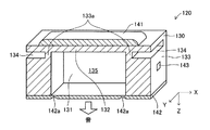
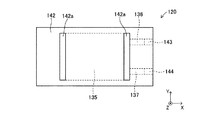
スピーカ本体120は、その斜視図を表す図3、図3の平面p1(スピーカ本体120のY軸方向中央位置に対応するX−Z平面に沿った平面)にてスピーカ本体120を切断した断面図である図4、その平面図を表す図5、及びその下面図を表す図6に示すように、各辺が互いに直交するX,Y,Z軸に平行に延びる略直方体形状を有しているセラミックスからなる基体部130と、基体部130の上面(Z軸負方向のX−Y平面に沿った平面)の所定位置に固定配置された圧電/電歪素子141と、基体部130の下面(Z軸正方向のX−Y平面に沿った平面)に同下面全域を覆うように固定配置された金属製の振動板142とを備えている。
The speaker
基体部130には、下方(Z軸正方向)に向けて開口する直方体形状の凹部131が形成されている。これにより、基体部130には、凹部131の底板を構成する駆動板部132と、凹部131の側面を構成するとともに基体部130の側面を構成する固定部133とが形成されている。この結果、駆動板部132と振動板142は、固定部133に支持されるようになっている。
The
固定部133における駆動板部132を支持する部分である支持部133aには、駆動板部132の平面(X−Y平面)に沿った方向に窪んだ左右一対の溝134,134が形成されている。これにより、固定部133における支持部133aは固定部133における他の部分よりも駆動板部132の平面(X−Y平面)に沿った方向の断面積が小さくなっている。
A pair of left and
圧電/電歪素子141は、複数の層状電極と複数の圧電/電歪層(本例では、4つの圧電/電歪層)を有し、層状の電極と圧電/電歪層とが交互に上下方向(Z軸方向)に積層された積層体であり、各辺が互いに直交するX,Y,Z軸に平行に延びる略直方体形状を有している。圧電/電歪素子141は、その中央部が駆動板部132の上面(Z軸負方向のX−Y平面に沿った平面)における凹部131に対応する部分に固定配置されていて、その左右両端部(X軸方向両端部)が駆動板部132の上面における支持部133aに対応する部分にまで延びている。
The piezoelectric /
振動板142は、前記振動板部を構成している。振動板142における凹部131に対応する部分における左右両端部(X軸方向の両端部。振動板部の縁部の少なくとも一部)の下面(Z軸正方向のX−Y平面に沿った平面)には、Y軸方向に延びた断面円弧状の一対の溝142a,142aが設けられている。これにより、振動板142の溝142a,142aに対応する部分(振動板部の縁部の少なくとも一部)は振動板142の中央部よりも厚さが薄くなっている。
The
基体部130の凹部131は、振動板142により塞がれている。この結果、駆動板部132の下面と、振動板142(振動板部)の上面と、固定部133の側面とでキャビティ135が区画形成されている。固定部133には、キャビティ135内と外部とを連通する媒体注入用の通路136,137が形成されていて、通路136,137はそれぞれ、封止栓143,144にて封がなされている。これにより、キャビティ135は密閉空間を構成していて、このキャビティ135内には所定の成分からなる媒体(本例では、ゲル)が封入されている。
The
次に、スピーカ本体120の製造方法について説明する。スピーカ本体120におけるセラミックスからなる基体部130(即ち、駆動板部132及び固定部133)は、セラミックグリーンシート積層法を用いて製造されることが好ましい。セラミックグリーンシート積層法によれば、複雑な形状を有する基体部130を一体的に成形することが可能であり、且つ、各シート間の接合部の経時的な状態変化がほとんど生じないため接合部位の信頼性を高くすることができ、剛性を確保することができるからである。従って、本例では、基体部130をセラミックグリーンシート積層法を用いて製造する。
Next, a method for manufacturing the
先ず、ジルコニア、アルミナ、窒化珪素、窒化アルミニウム、チタニア、マグネシア、ムライト等のセラミック粉末にバインダ、溶剤、分散剤、可塑剤等を添加混合してスラリーを作製し、これを脱泡処理後、リバースロールコーター法、ドクターブレード法等の方法により、所定の厚みを有する長方形のセラミックグリーンシートを作製する。ここで、ジルコニア、特に安定化ジルコニアを主成分とする材料と部分安定化ジルコニアを主成分とする材料は、機械的強度や靭性が高い点において基体部130(即ち、駆動板部132及び固定部133)の材料として好ましい。
First, a slurry is prepared by adding a binder, a solvent, a dispersant, a plasticizer, etc. to a ceramic powder such as zirconia, alumina, silicon nitride, aluminum nitride, titania, magnesia, mullite, etc. A rectangular ceramic green sheet having a predetermined thickness is produced by a method such as a roll coater method or a doctor blade method. Here, the zirconia, in particular, the material mainly composed of stabilized zirconia and the material mainly composed of partially stabilized zirconia, are high in mechanical strength and toughness, and thus the base portion 130 (that is, the
次に、図7に示したように、必要に応じて金型を用いた打抜加工やレーザ加工等の方法によりセラミックグリーンシートを種々の形状に加工し、複数枚のセラミックグリーンシート151〜156を得る。なお、セラミックグリーンシート151〜156の平面の各辺の長さ(長方形の平面の縦横の辺の長さ)は、積層後に切断により規定されてもよい。これにより、積層時においては、長方形の同じ外形を有するセラミックグリーンシートを使用することができ、加工精度を高めることができる。
Next, as shown in FIG. 7, the ceramic green sheets are processed into various shapes by a method such as punching using a mold or laser processing as necessary, and a plurality of ceramic
図7に示した例においては、セラミックグリーンシート152〜156に対して、後にキャビティ135を構成する長方形の窓Wd1〜Wd5をそれぞれ形成する。窓Wd1〜Wd5は同一形状である。セラミックグリーンシート152には、後に溝134,134を構成する切欠きK1,K2を形成する。セラミックグリーンシート154,155には、後に通路136,137を構成する溝G1,G2をそれぞれ形成する。なお、セラミックグリーンシートの枚数は、あくまでも一例である。また、図示された例では、セラミックグリーンシート153,156は、所定の厚みを有する一枚のグリーンシートでもよく、或いは、同所定の厚みを得るために複数枚のセラミックグリーンシートを積層する又は積層したものであってもよい。
In the example shown in FIG. 7, rectangular windows Wd <b> 1 to Wd <b> 5 that later constitute the
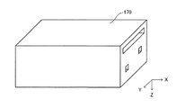
その後、図8に示したように、セラミックグリーンシート151〜156を積層・圧着してセラミックグリーンシート積層体160を形成する。次いで、そのセラミックグリーンシート積層体を焼成して図9に示したセラミック積層体170を形成する。
Thereafter, as shown in FIG. 8, ceramic
次に、図10に示すように、セラミック積層体170の上面(Z軸負方向のX−Y平面に沿った平面)、即ち、積層されたセラミックグリーンシート151の焼成後の表面に圧電/電歪層積層体180を形成する。ここで、各圧電/電歪層の上下面には必要に応じ電極が配設される。圧電/電歪層としては、例えば、ジルコン酸チタン酸鉛(PZT)やチタン酸バリウム、ニオブ酸カリウムナトリウムが適用できる。また、電極としては金、銀、白金等が必要に応じ使用される。圧電/電歪層積層体180及び電極の形成法としては、スクリーン印刷法、ディッピング法、塗布法、及び電気泳動法等の厚膜形成法や、イオンビーム法、スパッタリング法、真空蒸着、イオンプレーティング法、化学気相成長法(CVD)、及びめっき等の薄膜形成法を用いることができる。
Next, as shown in FIG. 10, piezoelectric / electrical current is applied to the upper surface of the ceramic laminate 170 (a plane along the XY plane in the negative Z-axis direction), that is, the fired surface of the laminated ceramic
次に、圧電/電歪層積層体180が形成されたセラミック積層体170を一体で焼成することで圧電/電歪素子141が形成された基体部130を形成する。これにより、基体部130の駆動板部132と圧電/電歪素子141とが一体化される。このように、膜形成法(特に、厚膜形成法)を用いて圧電/電歪層積層体180を形成することにより、接着剤を用いることなく、圧電/電歪層積層体180とセラミック積層体170(従って、圧電/電歪素子141と基体部130)とを一体的に接合(配設)することができる。
Next, the
なお、セラミックグリーンシート積層体160の上面(Z軸負方向のX−Y平面に沿った平面)、即ち、積層されたセラミックグリーンシート151の焼成前の表面に圧電/電歪層積層体180を形成しておき、そのセラミックグリーンシート積層体160と圧電/電歪層積層体180とを同時に焼成してもよい。
In addition, the piezoelectric / electrostrictive layer laminate 180 is formed on the upper surface of the ceramic green sheet laminate 160 (a plane along the XY plane in the negative Z-axis direction), that is, on the surface of the laminated ceramic
また、「圧電/電歪素子141が形成された基体部130」の製造にあたっては、図9のセラミック積層体を縦横に複数個並べたものと同等の1枚のシートを準備し、このシートの表面に後に圧電/電歪素子141となる圧電/電歪層積層体180(図10を参照。)を所定の部位に複数個分だけ連続させたものを形成し、このシートを切断することで、同一工程で多数個の「圧電/電歪素子141が形成された基体部130」を製造することが望ましい。
Further, in manufacturing the “
次いで、図11に示すように、基体部130の下面(Z軸正方向のX−Y平面に沿った平面)、即ち、積層されたセラミックグリーンシート156の焼成後の表面に、予め作製してある金属製の振動板142を接着剤にて接着固定する。
Next, as shown in FIG. 11, it is prepared in advance on the lower surface of the base portion 130 (a plane along the XY plane in the Z-axis positive direction), that is, on the surface after firing of the laminated ceramic
そして、振動板142が接着された基体部130の通路136,137を利用して基体部130内のキャビティ135内にゲルを注入し、最後に、通路136,137に封止栓143,144をそれぞれ嵌めることでゲルをキャビティ135内に封入する。このようにして、スピーカ本体120が製造される。
Then, the gel is injected into the
次に、このように製造・構成される本発明の第1実施形態に係る、スピーカ本体120が埋設されたスピーカ100の作動について説明する。圧電/電歪素子141に電気的に接続されている図示しない駆動回路から駆動信号としてのオーディオ信号が圧電/電歪素子141に供給されると、圧電/電歪素子141は、オーディオ信号に応じてX軸方向に沿って伸縮変位する。
Next, the operation of the
これにより、圧電/電歪素子141と一体化されている駆動板部132が振動し、その振動がキャビティ135内に封入されているゲルを介して振動板142に伝達される。これにより振動板142が振動する。この振動板142の振動は、エンクロージャ110の開口部111を通して音波として外部に放射される。この結果、オーディオ信号のパターンに応じた音がスピーカ100から発生する。
As a result, the
ところで、この第1実施形態では、上述したように、セラミックスからなる駆動板部132と圧電/電歪素子141とが焼成により確実に一体化されていて、駆動板部132と圧電/電歪素子141との境界面全域に亘って駆動板部132と圧電/電歪素子141とが接合され得る。この結果、圧電/電歪素子141の伸縮変位が駆動板部132(ひいては、キャビティ135内のゲル)に正確、且つ十分に伝達され得る。従って、音の再現性の低下、及び音圧の低下を抑制することができる。
By the way, in the first embodiment, as described above, the driving
また、第1実施形態では、左右一対の溝134,134の形成により、上述したように、固定部133における駆動板部132を支持する部分である支持部133aは、固定部133における他の部分よりも駆動板部132の平面(X−Y平面)に沿った方向の断面積が小さくなっている。これにより、固定部133は、支持部133aが他の部分よりも変形し易い構造となっている。この結果、駆動板部132の共振周波数を低下させることができ、低音域での音圧を高めることができる。
In the first embodiment, as described above, the
また、第1実施形態では、左右一対の溝142a,142aの形成により、上述したように、振動板142の溝142a,142aに対応する部分(振動板部の縁部の少なくとも一部)は振動板142の中央部よりも厚さが薄くなっている。これにより、振動板142は、振動板部の縁部の少なくとも一部が振動板142の中央部よりも変形し易い構造となっている。これにより、振動板142の中央部が殆ど変形することなく振動板部の縁部の少なくとも一部のみが積極的に変形することで振動板142が振動する。換言すれば、振動板142が振動する際、振動板142の中央部の広い範囲が振動板142の平面に垂直方向に大きく変位し得る。従って、振動板142の振動により排除される空気の量を大きくすることができ、この結果、音圧を大きくすることができる。また、振動板142の中央部の広い範囲が振動板142の平面に垂直方向に大きく変位することで指向性の高い音を発することができる。
Further, in the first embodiment, as described above, the portion corresponding to the
また、第1実施形態では、振動板142の平面がエンクロージャ110の上面よりも所定高さだけ低い位置(図2においてZ軸負方向の位置)になるようにスピーカ本体120がエンクロージャ110内に埋設されている。これにより、指向性を高くすることができ、且つ、音圧を大きくすることができる。
In the first embodiment, the
また、第1実施形態では、キャビティ内に封入される媒体としてゲルが使用されている。これにより、基体部130と振動板142との接合面における、媒体の外部への漏れを防止するためのシール構造を簡易とすることができる。
In the first embodiment, a gel is used as a medium enclosed in the cavity. Thereby, the seal structure for preventing the leakage of the medium to the outside at the joint surface between the
以上、説明したように、本発明の第1実施形態に係るスピーカ100によれば、音の再現性の低下、及び音圧の低下を抑制し得るものを提供することができる。
As described above, according to the
本発明は上記第1実施形態に限らず、本発明の範囲内において種々の変形例を採用することができる。例えば、上記第1実施形態においては、振動板部の縁部の少なくとも一部が振動板142の中央部よりも変形し易い構造を得るために、振動板部として、左右一対の溝142a,142aが形成された振動板142を使用しているが、図12に示すように、振動板部として、左右一対の溝142a,142aに対応する部分の材質のみを金属よりもヤング率の小さい材質(例えば、ゴム等)に変更した金属製の振動板142’を使用してもよい。なお、ヤング率の小さい材料は、使用される周波数による特性(例えば、共振周波数等)に着目して適宜選択すればよい。また、キャビティ内に充填されるゲルと同種の材料を用いてもよい。
The present invention is not limited to the first embodiment, and various modifications can be employed within the scope of the present invention. For example, in the first embodiment, in order to obtain a structure in which at least a part of the edge of the diaphragm part is more easily deformed than the center part of the
また、上記第1実施形態においては、駆動板部132におけるキャビティ135と接する部分の面積と、振動板142におけるキャビティ135と接する部分の面積とが等しいが、図13に示すように、振動板142に近づくにつれて振動板142の平面に沿った方向の断面積が小さくなるキャビティ135’を有する基体部130’を使用することで、振動板142におけるキャビティ135’と接する部分の面積を、駆動板部132’におけるキャビティ135’と接する部分の面積よりも小さくしてもよい。このような、基体部130’は、セラミックグリーンシートの枚数、形状等を変更することで形成され得る。これにより、振動板142の(Z軸方向の)振幅を大きくすることができ、音圧の増大が期待できる。
In the first embodiment, the area of the portion of the
また、上記第1実施形態においては、振動板部として、金属製の振動板142が使用されているが、振動板部として、基体部130を構成するセラミックスよりも変形し易い(ヤング率が小さい)他の材質(例えば、樹脂フィルム等)からなる振動板を使用してもよい。また、セラミックグリーンシート積層法を用いて基体部と振動板部とを一体的に成形してもよい。
In the first embodiment, the
(第2実施形態)
次に、本発明の第2実施形態に係るスピーカ200について説明する。このスピーカ200は、固定部における駆動板部を支持する支持部が固定部における他の部分よりも変形し易い構造を得るために、セラミックスからなる固定部における支持部に対応する部分の材質のみをセラミックスよりもヤング率の小さい材質(本例では、ゴム)に変更した点のみが第1実施形態に係るスピーカ100と異なる。
(Second Embodiment)
Next, the speaker 200 according to the second embodiment of the present invention will be described. In order to obtain a structure in which the support portion that supports the drive plate portion in the fixed portion is more easily deformed than the other portions in the fixed portion, this speaker 200 is made of only the material of the portion corresponding to the support portion in the fixed portion made of ceramics. The only difference from the
即ち、スピーカ200は、図1、図2に示したエンクロージャ110と、第1実施形態のスピーカ本体120と同形であってスピーカ本体120と同様にエンクロージャ110内に埋設された第2実施形態用のスピーカ本体220とから構成されている。
That is, the speaker 200 has the same shape as the
以下、スピーカ本体220について、その斜視図を表す図14、図14の平面p2(スピーカ本体220のY軸方向中央位置に対応するX−Z平面に沿った平面)にてスピーカ本体220を切断した断面図である図15、その平面図を表す図16、及びその下面図を表す図17を参照しながら説明する。第2実施形態用のスピーカ本体220における各部材、部位等に付される符号として、第1実施形態用のスピーカ本体120における対応する各部材、部位等の符号に対して百の位のみが異なるものをそれぞれ使用することで、スピーカ本体220における各部材、部位等の説明に代える(後述する第3実施形態以降の実施形態でも同様)。
Hereinafter, the speaker
図14〜図17に示すように、スピーカ本体220では、セラミックスからなる固定部233における第1実施形態の支持部133a及び溝134に対応する部分に、ゴムからなる支持部233aが設けられている。換言すれば、駆動板部232は、ゴムからなる支持部233aに支持されている。
As shown in FIGS. 14-17, in the speaker
以下、スピーカ本体220の製造方法について説明する。先ず、第1実施形態と同様、ドクターブレード法等の方法により、所定の厚みを有する長方形のセラミックグリーンシートを作製する。
Hereinafter, a method for manufacturing the
次に、図18に示したように、必要に応じて金型を用いた打抜加工やレーザ加工等の方法によりセラミックグリーンシートを種々の形状に加工し、複数枚のセラミックグリーンシート251〜256を得る。
Next, as shown in FIG. 18, the ceramic green sheets are processed into various shapes by a method such as punching using a mold or laser processing as necessary, and a plurality of ceramic
図18に示した例においては、セラミックグリーンシート253〜256に対して、後にキャビティ235を構成する長方形の窓Wd11〜Wd14をそれぞれ形成する。窓Wd11〜Wd14は同一形状である。セラミックグリーンシート251には、支持部233aを構成するゴムを後述するように流し込むための窓Wd15を形成する。セラミックグリーンシート252には、後にキャビティ235を構成するとともに、支持部233aに対応する部分に上記流し込まれたゴムを保持するための空間を確保するための窓Wd16を形成する。換言すれば、窓Wd16は、窓Wd11〜Wd14に対して、上記流し込まれたゴムを保持するための空間に対応する分だけ左右方向に広い形状を有している。
In the example shown in FIG. 18, rectangular windows Wd11 to Wd14 that
セラミックグリーンシート254,255には、後に通路236,237を構成する溝G11,G12をそれぞれ形成する。なお、セラミックグリーンシートの枚数は、あくまでも一例である。また、図示された例では、セラミックグリーンシート253,256は、所定の厚みを有する一枚のグリーンシートでもよく、或いは、同所定の厚みを得るために複数枚のセラミックグリーンシートを積層する又は積層したものであってもよい。
The ceramic
その後、図19に示したように、セラミックグリーンシート251〜256を積層・圧着してセラミックグリーンシート積層体260を形成する。次いで、そのセラミックグリーンシート積層体を焼成して図20に示したセラミック積層体270を形成する。
Thereafter, as shown in FIG. 19, ceramic
次に、図21に示すように、セラミック積層体270の上面(Z軸負方向のX−Y平面に沿った平面)、即ち、積層されたセラミックグリーンシート251の焼成後の表面に圧電/電歪層積層体280を形成する。圧電/電歪層積層体280の形成法としては、第1実施形態と同様、スクリーン印刷法等を用いることができる。
Next, as shown in FIG. 21, piezoelectric / electrical current is applied to the upper surface of the ceramic laminate 270 (a plane along the XY plane in the negative Z-axis direction), that is, the fired surface of the laminated ceramic
次いで、圧電/電歪層積層体280が形成されたセラミック積層体270を一体で焼成することで圧電/電歪素子241を形成する。これにより、第1実施形態と同様、接着剤を用いることなく、圧電/電歪層積層体280とセラミック積層体270とを一体的に接合(配設)することができる。
Next, the
続いて、この「圧電/電歪素子241が形成されたセラミック積層体270」の上面にある上記窓Wd15に対応する一対の窓から高温の液体ゴム(ゴム前駆体)を流し込む。その際、液体ゴムが後にキャビティ235を構成する空間内に流入することを防止するため、キャビティ235と同形の凸部を有する治具を準備し、この治具の凸部を後にキャビティ235を構成する空間内に嵌めこんだ状態で液体ゴムを流し込むことが好ましい。これにより、後に支持部233aを構成する部分に液体ゴムが確実に保持・充填される。
Subsequently, high-temperature liquid rubber (rubber precursor) is poured from a pair of windows corresponding to the window Wd15 on the upper surface of the “
次に、所定時間に亘る常温放置により液体ゴムを固化させた後、図21に示した切断線C1,C2に沿ってセラミック積層体270を切断して基体部230を形成する。これにより、図22に示すように、「圧電/電歪素子241が形成された基体部230」が形成される。
Next, after the liquid rubber is solidified by standing at room temperature for a predetermined time, the
次いで、図23に示すように、基体部230の下面(Z軸正方向のX−Y平面に沿った平面)、即ち、積層されたセラミックグリーンシート256の焼成後の表面に、予め作製してある金属製の振動板242を接着剤にて接着固定する。
Next, as shown in FIG. 23, it is prepared in advance on the lower surface of the base portion 230 (a plane along the XY plane in the positive Z-axis direction), that is, on the surface after firing of the laminated ceramic
そして、振動板242が接着された基体部230の通路236,237を利用して基体部230内のキャビティ235内にゲルを注入し、最後に、通路236,237に封止栓243,244をそれぞれ嵌めることでゲルをキャビティ235内に封入する。このようにして、スピーカ本体220が製造される。
Then, gel is injected into the
このように、第2実施形態では、セラミックスからなる固定部233において、駆動板部232を支持する支持部233aのみがゴムから構成されている。これにより、第1実施形態と同様、固定部233は、支持部233aが他の部分よりも変形し易い構造となっている。この結果、駆動板部232の共振周波数を低下させることができ、低音域での音圧を高めることができる。
Thus, in 2nd Embodiment, in the fixing |
本発明は上記第2実施形態に限らず、本発明の範囲内において種々の変形例を採用することができる。例えば、上記第2実施形態においては、第1実施形態と同様、振動板部の縁部の少なくとも一部が振動板242の中央部よりも変形し易い構造を得るために、振動板部として、左右一対の溝242a,242aが形成された振動板242を使用しているが、上述した図12に示すように、振動板部として、左右一対の溝242a,242aに対応する部分の材質のみを金属よりもヤング率の小さい材質(例えば、ゴム等)に変更した金属製の振動板を使用してもよい。
The present invention is not limited to the second embodiment, and various modifications can be employed within the scope of the present invention. For example, in the second embodiment, as in the first embodiment, in order to obtain a structure in which at least a part of the edge of the diaphragm portion is more easily deformed than the center portion of the
また、上記第2実施形態においては、振動板部として、金属製の振動板242が使用されているが、第1実施形態と同様、振動板部として、基体部230を構成するセラミックスよりも変形し易い(ヤング率が小さい)他の材質(例えば、樹脂フィルム等)からなる振動板を使用してもよい。また、セラミックグリーンシート積層法を用いて基体部と振動板部とを一体的に成形してもよい。
In the second embodiment, the
(第3実施形態)
次に、本発明の第3実施形態に係るスピーカ300について説明する。このスピーカ300は、駆動板部が複数(3つ)設けられていて、それぞれの駆動板部の上に圧電/電歪素子がそれぞれ固定配置されている点が第1実施形態に係るスピーカ100と主として異なる。
(Third embodiment)
Next, a speaker 300 according to a third embodiment of the present invention will be described. The speaker 300 is provided with a plurality (three) of drive plate portions, and the piezoelectric / electrostrictive elements are fixedly arranged on the drive plate portions, respectively, with the
即ち、スピーカ300は、図1、図2に示したエンクロージャ110と、エンクロージャ110内に埋設された第3実施形態用のスピーカ本体320とから構成されている。
That is, the speaker 300 includes the
以下、スピーカ本体320について、その斜視図を表す図24、図24の平面p3(スピーカ本体320のY軸方向中央位置に対応するX−Z平面に沿った平面)にてスピーカ本体320を切断した断面図である図25、その平面図を表す図26、及びその下面図を表す図27を参照しながら説明する。なお、媒体注入用の通路、及び封止栓は図示省略されている(後述する第4実施形態以降の実施形態でも同様)。
Hereinafter, the speaker
図24〜図27に示すスピーカ本体320の基体部330は、第1、第2実施形態と同様、セラミックグリーンシート積層法により形成されている。基体部330内におけるゲルが封入されたキャビティは、キャビティ335aと、キャビティ335bと、キャビティ335cと、キャビティ335dと、の4つに区画されている。これらの4つのキャビティは、連通孔338a,338b,338cにより互いに連通している。
The
キャビティ335a、キャビティ335b、キャビティ335cのそれぞれの上部(Z軸負方向)に対応する位置には、駆動板部332a,332b,332cが設けられている。駆動板部332a,332b,332cの上面(Z軸負方向のX−Y平面に沿った平面)には、圧電/電歪素子341a,341b,341cがそれぞれ焼成により形成・一体化されている。
Drive
前記振動板部を構成する金属製の振動板342は、基体部330の下面(Z軸正方向のX−Y平面に沿った平面)に接着固定されている。振動板342におけるキャビティ335dに対応する部分における左右両端部(X軸方向の両端部。振動板部の縁部の少なくとも一部)の下面(Z軸正方向のX−Y平面に沿った平面)には、Y軸方向に延びた襞状の一対の屈曲部342a,342aが設けられている。
A
このように、第3実施形態では、複数(3つ)の駆動板部の上に圧電/電歪素子がそれぞれ固定配置されている。これにより、同一のパターンのオーディオ信号を複数の圧電/電歪素子のそれぞれに供給することで、1つの駆動板部の上に1つの圧電/電歪素子が固定配置される場合に比して、圧電/電歪素子の伸縮変位による駆動板部の変形量の総和を大きくすることができる。従って、媒体(ゲル)を介して振動板342に伝達される振動(の振幅)を大きくすることができる。従って、振動板342の振動(の振幅)が大きくなり、音圧を大きくすることができる。
As described above, in the third embodiment, the piezoelectric / electrostrictive elements are fixedly arranged on a plurality (three) of the drive plate portions. As a result, by supplying an audio signal having the same pattern to each of the plurality of piezoelectric / electrostrictive elements, compared to a case where one piezoelectric / electrostrictive element is fixedly arranged on one drive plate portion. In addition, the total sum of deformation amounts of the drive plate portion due to the expansion / contraction displacement of the piezoelectric / electrostrictive element can be increased. Therefore, vibration (amplitude) transmitted to the
また、第3実施形態では、左右一対の襞状の屈曲部342a,342aの形成により、振動板342は、振動板部の縁部の少なくとも一部が振動板342の中央部よりも変形し易い構造となっている。これにより、振動板342の中央部が殆ど変形することなく振動板部の縁部の少なくとも一部のみが積極的に変形することで振動板342が振動する。従って、振動板342の振動により排除される空気の量を大きくすることができ、この結果、音圧を大きくすることができる。
In the third embodiment, due to the formation of the pair of left and right bowl-shaped
(第4実施形態)
次に、本発明の第4実施形態に係るスピーカ400について説明する。このスピーカ400は、駆動板部と振動板部とが同一平面上に存在する点が第3実施形態に係るスピーカ300と主として異なる。
(Fourth embodiment)
Next, a speaker 400 according to a fourth embodiment of the present invention will be described. The speaker 400 is mainly different from the speaker 300 according to the third embodiment in that the drive plate portion and the diaphragm portion are on the same plane.
また、これにより、振動板部の振動により外部に放射される音波と駆動板部の振動により外部に放射される音波との向きと位相を一致させて使用することで、振動板部の振動により外部に放射される音波と駆動板部の振動により外部に放射される音波との干渉を防止するためのエンクロージャが不要となる。即ち、スピーカ400は、第4実施形態用のスピーカ本体420のみから構成されている。
In addition, by using the sound wave radiated to the outside by the vibration of the vibration plate part and the sound wave radiated to the outside by the vibration of the driving plate part in the same direction and phase, An enclosure for preventing the interference between the sound wave radiated to the outside and the sound wave radiated to the outside due to the vibration of the drive plate portion becomes unnecessary. That is, the speaker 400 includes only the
以下、スピーカ本体420について、その斜視図を表す図28、図28の平面p4(スピーカ本体420のY軸方向中央位置に対応するX−Z平面に沿った平面)にてスピーカ本体420を切断した断面図である図29、その平面図を表す図30、及びその下面図を表す図31を参照しながら説明する。
Hereinafter, the speaker
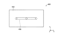
図28〜図31に示すスピーカ本体420の基体部430は、第1〜第3実施形態と同様、セラミックグリーンシート積層法により形成されている。基体部430内におけるゲルが封入されたキャビティは、キャビティ335aと、キャビティ335bと、キャビティ335cと、の3つに区画されている。これらの3つのキャビティは、連通孔438により互いに連通している。
The
キャビティ335a、キャビティ335b、キャビティ335cのそれぞれの上部(Z軸負方向)に対応する位置には、振動板部442a、駆動板部432、振動板部442bが設けられている。即ち、本例では、固定部433と駆動板部432のみならず、振動板部442a,442bもがセラミックグリーンシート積層法により一体成形されている。駆動板部432と振動板部442a,442bとは、同一平面上(基体部430の上面)に存在している。駆動板部432の上面(Z軸負方向のX−Y平面に沿った平面)には、圧電/電歪素子441が焼成により形成・一体化されている。
A
以上のように、この第4実施形態のスピーカ本体420は、第3実施形態のスピーカ本体320(図25を参照)に対して、キャビティ335d、金属製の振動板342、及び圧電/電歪素子341a,341cを除去し、且つ、駆動板部332a,332cを振動板部として機能させたものに相当する。
As described above, the
このように、第4実施形態では、駆動板部432と振動板部442a,442bとが同一平面上(基体部430の上面)に存在しているからエンクロージャが不要となる。従って、スピーカ400全体をコンパクトにすることができる。特に、スピーカ400における音(音波)が放射される方向(Z軸方向)における長さを短くすることができる。
As described above, in the fourth embodiment, the
(第5実施形態)
最後に、本発明の第5実施形態に係るスピーカ500について説明する。このスピーカ500は、駆動板部を省略し、内側に内部空間を有する圧電/電歪素子の同内部空間をキャビティの一部として使用する点が第1実施形態に係るスピーカ100と主として異なる。
(Fifth embodiment)
Finally, a speaker 500 according to a fifth embodiment of the present invention will be described. The speaker 500 is mainly different from the
即ち、スピーカ500は、図1、図2に示したエンクロージャ110と、エンクロージャ110内に埋設された第5実施形態用のスピーカ本体520とから構成されている。
That is, the speaker 500 includes the
以下、スピーカ本体520について、その斜視図を表す図32、図32の平面p5(スピーカ本体520のY軸方向中央位置に対応するX−Z平面に沿った平面)にてスピーカ本体520を切断した断面図である図33、その平面図を表す図34、及びその下面図を表す図35を参照しながら説明する。
Hereinafter, the
図32〜図35に示すように、スピーカ本体520は、圧電/電歪素子541と、固定部533と、第1実施形態の振動板142と同じ振動板542とから構成されている。圧電/電歪素子541は、下方(Z軸正方向)に向けて開口する直方体形状の内部空間541aを有する略直方体形状を有している。この圧電/電歪素子541は、複数(例えば、4つ)の圧電/電歪層と、各圧電/電歪層の上下面にそれぞれ配設される電極とから構成される複数の圧電/電歪素子を順に(Z軸方向に)積層してなる多数の圧電/電歪層から構成されている。
As shown in FIGS. 32 to 35, the
固定部533は、樹脂(プラスチック)からなり、その中央部に内部空間541aに対応する窓が形成された直方体形状を有している。固定部533は、圧電/電歪素子541の下面(Z軸負方向のX−Y平面に沿った平面)に接着固定されている。
The fixing
振動板542は、固定部の下面(Z軸負方向のX−Y平面に沿った平面)に接着固定されている。これにより、圧電/電歪素子541の内部空間541aと、固定部533の窓に対応する空間とから密閉空間であるキャビティ535が形成されている。このキャビティ535内には、所定の媒体(ゲル)が封入されている。
The
次に、このように構成される第5実施形態に係るスピーカ本体520が埋設されたスピーカ500の作動について説明する。圧電/電歪素子541に電気的に接続されている図示しない駆動回路から駆動信号としてのオーディオ信号が圧電/電歪素子541に供給されると、圧電/電歪素子541は、オーディオ信号に応じてX軸方向に沿って伸縮変位する。
Next, the operation of the speaker 500 in which the
これにより、圧電/電歪素子541そのものが振動し、その振動がキャビティ535内に封入されているゲルに直接伝達されるとともにゲルを介して振動板542に伝達される。これにより振動板542が振動する。この振動板542の振動は、エンクロージャ110の開口部111を通して音波として外部に放射される。この結果、オーディオ信号のパターンに応じた音がスピーカ500から発生する。
As a result, the piezoelectric /
この結果、圧電/電歪素子541の伸縮変位がキャビティ535内のゲルに正確、且つ十分に伝達され得る。従って、音の再現性の低下、及び音圧の低下を抑制することができる。
As a result, the expansion / contraction displacement of the piezoelectric /
以上、説明したように、本発明の各実施形態に係るスピーカによれば、圧電/電歪素子の伸縮変位がキャビティ内の媒体(ひいては、振動板部)に正確、且つ十分に伝達され得る。従って、音の再現性の低下、及び音圧の低下を抑制することができる。 As described above, according to the loudspeaker according to each embodiment of the present invention, the expansion / contraction displacement of the piezoelectric / electrostrictive element can be accurately and sufficiently transmitted to the medium (and hence the diaphragm portion) in the cavity. Accordingly, it is possible to suppress a decrease in sound reproducibility and a decrease in sound pressure.
本発明は上記各実施形態に限らず、本発明の範囲内において種々の変形例を採用することができる。例えば、上記各実施形態においては、キャビティ内に封入される媒体としてゲルが使用されているが、粘性液体や水等の液体が使用されてもよい。また、ヘリウムガス等の気体であってもよい。 The present invention is not limited to the above embodiments, and various modifications can be employed within the scope of the present invention. For example, in each of the above embodiments, a gel is used as a medium enclosed in the cavity, but a liquid such as a viscous liquid or water may be used. Further, a gas such as helium gas may be used.
また、上記各実施形態においては、キャビティ内において媒体が直接封入されているが、キャビティ内において高分子フィルム等の薄膜で包まれた媒体を封入してもよい。この場合、キャビティ内に、先ず、薄膜の前駆体である液体を注入し、キャビティの内壁面の総ての部分に接触するように袋状の薄膜を形成しておく。その後、キャビティ内において袋状の薄膜の内部空間内に媒体を注入する。これにより、薄膜で包まれた媒体をキャビティ内に封入することができる。また、高分子フィルム等の薄膜を準備することなく、ゲルの内部に流動性をもたせるように、ゲルの外周部(表面部)のみを固化させてもよい。 In each of the above embodiments, the medium is directly enclosed in the cavity. However, a medium wrapped with a thin film such as a polymer film may be enclosed in the cavity. In this case, first, a liquid which is a thin film precursor is injected into the cavity, and a bag-like thin film is formed so as to be in contact with all the inner wall surfaces of the cavity. Thereafter, the medium is injected into the internal space of the bag-like thin film in the cavity. Thereby, the medium wrapped with the thin film can be enclosed in the cavity. Moreover, you may solidify only the outer peripheral part (surface part) of a gel so that a fluidity may be given inside a gel, without preparing thin films, such as a polymer film.
また、上記第5実施形態においては、圧電/電歪素子として、1つの内部空間を有するものが使用されているが、内部空間が複数の空間に区画されているものが使用されてもよい。この場合、具体的には、例えば、内部空間がZ軸方向を長手方向とする細長い直方体状の多数の空間に区画されたものが考えられる。このような形状の圧電/電歪素子は、例えば、圧電/電歪素子の圧電/電歪層を、その前駆体(スラリー)を格子状のスリットから押し出して成形する(詳細は、例えば、特開平2―251406号公報を参照)。その後、必要に応じて目封じを行い、圧電/電歪層を焼成により形成する。そして、スクリーン印刷法、ディッピング法、塗布法、及び電気泳動法等の厚膜形成法や、イオンビーム法、スパッタリング法、真空蒸着、イオンプレーティング法、化学気相成長法(CVD)、及びめっき等の薄膜形成法により、圧電/電歪素子の電極を上記形成された圧電/電歪層の所定の表面上に形成する。これにより、このような形状の圧電/電歪素子が作製され得る。これによれば、圧電/電歪素子の振動(圧力波)がより一層効率的に振動板部に伝達され得る。 In the fifth embodiment, a piezoelectric / electrostrictive element having one internal space is used, but one having an internal space partitioned into a plurality of spaces may be used. In this case, specifically, for example, the internal space may be divided into a number of elongated rectangular parallelepiped spaces whose longitudinal direction is the Z-axis direction. The piezoelectric / electrostrictive element having such a shape is formed by, for example, forming a piezoelectric / electrostrictive layer of a piezoelectric / electrostrictive element by extruding a precursor (slurry) from a lattice-like slit (for details, for example, a special (See Kaihei 2-251406). Thereafter, sealing is performed as necessary, and a piezoelectric / electrostrictive layer is formed by firing. And thick film forming methods such as screen printing, dipping, coating, and electrophoresis, ion beam, sputtering, vacuum deposition, ion plating, chemical vapor deposition (CVD), and plating The electrode of the piezoelectric / electrostrictive element is formed on a predetermined surface of the formed piezoelectric / electrostrictive layer by a thin film forming method such as the above. Thereby, a piezoelectric / electrostrictive element having such a shape can be manufactured. According to this, the vibration (pressure wave) of the piezoelectric / electrostrictive element can be transmitted to the diaphragm portion more efficiently.
また、上記第1〜第5実施形態、及び上述した種々の変形例においては、圧電/電歪素子に代えて、超磁歪材料を用いた超磁歪素子が使用されてもよい。超磁歪素子は圧電/電歪素子に比してより大きい変位量を得ることが可能であるから、これにより、音圧をより大きくすることができる。なお、超磁歪材料とは、磁歪材料のうち磁歪が数千ppmであるものを指し、例えば、Tb−Dy−Fe系合金などをいう。 In the first to fifth embodiments and the various modifications described above, a giant magnetostrictive element using a giant magnetostrictive material may be used instead of the piezoelectric / electrostrictive element. Since the giant magnetostrictive element can obtain a larger displacement than the piezoelectric / electrostrictive element, the sound pressure can be further increased. The super magnetostrictive material refers to a magnetostrictive material having a magnetostriction of several thousand ppm, such as a Tb-Dy-Fe alloy.
ここで、上記第1〜第4実施形態、及びそれらの変形例において圧電/電歪素子に代えて超磁歪材料を用いた超磁歪素子が使用される場合、超磁歪素子は、駆動板部の上に固定配置される。この場合、超磁歪素子を駆動板部の上に、焼成で一体化させてもよいし、無機接着剤、熱圧着、陽極接合、拡散接合等で固着させてもよい。また、駆動板部としては、セラミックスの他、ガラス基板やシリコン基板のような半導体基板を用いてもよい。 Here, when a giant magnetostrictive element using a giant magnetostrictive material is used in place of the piezoelectric / electrostrictive element in the first to fourth embodiments and the modifications thereof, the giant magnetostrictive element is the driving plate portion. Fixedly placed on top. In this case, the giant magnetostrictive element may be integrated on the driving plate portion by firing, or may be fixed by an inorganic adhesive, thermocompression bonding, anodic bonding, diffusion bonding, or the like. Further, as the drive plate portion, a semiconductor substrate such as a glass substrate or a silicon substrate may be used in addition to ceramics.
また、上記第1〜第5実施形態、及び上述した種々の変形例において圧電/電歪素子に代えて超磁歪材料を用いた超磁歪素子が使用される場合、超磁歪素子を駆動する磁界を形成するために必要となる磁石やコイルは、超磁歪素子の周囲(側面)に直接一体的に配置してもよいし、エンクロージャの内壁面上に配置することで超磁歪素子の周囲(側面)と所定のギャップをもって対向させるように配置してもよい。 In the first to fifth embodiments and the various modifications described above, when a giant magnetostrictive element using a giant magnetostrictive material is used instead of the piezoelectric / electrostrictive element, a magnetic field for driving the giant magnetostrictive element is used. The magnets and coils necessary for forming the magnets and coils may be arranged directly and integrally around the giant magnetostrictive element (side surface), or around the giant magnetostrictive element by arranging them on the inner wall surface of the enclosure. And may be arranged to face each other with a predetermined gap.
また、上記各実施形態においては、圧電/電歪素子に電気的に接続されている図示しない駆動回路から駆動信号としてオーディオ信号が圧電/電歪素子に供給されているが、駆動信号としてオーディオ信号で振幅変調した超音波信号が圧電/電歪素子に供給されてもよい。これによると、超音波信号の供給により発生する圧電/電歪素子の振動(変位)に起因して媒体を介して振動板部が受ける力の大きさが、変調成分(オーディオ信号成分)に応じて変化する。従って、この変調成分に応じた音波が振動板部から外部に向けて放射される。従って、これによっても、オーディオ信号のパターンに応じた音が発生する。 In each of the above embodiments, an audio signal is supplied to the piezoelectric / electrostrictive element as a drive signal from a drive circuit (not shown) electrically connected to the piezoelectric / electrostrictive element. The ultrasonic signal that has been amplitude-modulated in (5) may be supplied to the piezoelectric / electrostrictive element. According to this, the magnitude of the force that the diaphragm receives through the medium due to the vibration (displacement) of the piezoelectric / electrostrictive element caused by the supply of the ultrasonic signal depends on the modulation component (audio signal component). Change. Accordingly, a sound wave corresponding to the modulation component is radiated from the diaphragm portion to the outside. Accordingly, this also generates a sound corresponding to the pattern of the audio signal.
加えて、上記第1〜第5実施形態、及び上述した種々の変形例において圧電/電歪素子に代えて超磁歪材料を用いた超磁歪素子が使用される場合であっても、駆動信号としてオーディオ信号で振幅変調した超音波信号が超磁歪素子に供給されてもよい。この場合も、圧電/電歪素子の場合と同様、オーディオ信号のパターンに応じた音が発生する。 In addition, even when a giant magnetostrictive element using a giant magnetostrictive material is used in place of the piezoelectric / electrostrictive element in the first to fifth embodiments and the various modifications described above, as a drive signal An ultrasonic signal amplitude-modulated with an audio signal may be supplied to the giant magnetostrictive element. Also in this case, as in the case of the piezoelectric / electrostrictive element, a sound corresponding to the audio signal pattern is generated.
また、上記各実施形態によるスピーカは、小型超音波発信機としても使用可能である。この小型超音波発信機は、指向性の高いイヤホンとしても使用され得る。 The speaker according to each of the above embodiments can also be used as a small ultrasonic transmitter. This small ultrasonic transmitter can also be used as a highly directional earphone.
更には、複数の上記小型超音波発信機を用いれば、デジタルなパルス波を発するイヤホンが作製可能である。ここで、デジタルなパルス波とは、アナログ信号、或いはデジタル信号を、パルス間隔が波長となるように変調したパルス波(縦波)を意味する。この場合、音量は、各発信機の稼動率、或いは振幅で制御され得る。 Furthermore, if a plurality of small ultrasonic transmitters are used, an earphone that emits a digital pulse wave can be produced. Here, the digital pulse wave means a pulse wave (longitudinal wave) obtained by modulating an analog signal or a digital signal so that a pulse interval has a wavelength. In this case, the volume can be controlled by the operating rate or amplitude of each transmitter.
ところで、例えば、図3〜図6に示したスピーカ本体120において、駆動板部132を出力板部として使用し、振動板142を入力板として使用することで、センサが提供され得る。
By the way, for example, in the speaker
より具体的に述べると、入力板に外部から力(圧力)を与えると、この力の大きさに応じて入力板が変形する。入力板が変形すると、この入力板の変形に応じてキャビティ135内の媒体(ゲル)の圧力が発生する。この媒体の圧力に応じて出力板部が変形する。出力板部が変形すると、この出力板部の変形に応じて圧電/電歪素子141が電力を発生する。
More specifically, when an external force (pressure) is applied to the input plate, the input plate is deformed according to the magnitude of the force. When the input plate is deformed, the pressure of the medium (gel) in the
以上より、入力板(例えば、ボタン等として機能する板)に外部から力(圧力)を与えると、圧電/電歪素子141はこの力の大きさに応じた電力(電圧)を発生する。従って、圧電/電歪素子141が発生する電力(電圧)を検出することで、このセンサは、例えば、入力板(例えば、ボタン)に与えられた力(圧力)の大きさをアナログ的に検出する力(圧力)センサとなり得る。
As described above, when a force (pressure) is applied to the input plate (for example, a plate functioning as a button) from the outside, the piezoelectric /
このセンサの利用形態としては、例えば、携帯電話のダイヤルボタンを上記入力板として機能させる形態が考えられる。この場合、ダイヤルボタンに与えられた力の大きさをアナログ的に検出できるから、例えば、携帯電話端末を用いたカーゲームにおいて、ダイヤルボタンをアクセル操作部材として使用することができる。 As a usage form of this sensor, for example, a form in which a dial button of a cellular phone functions as the input board can be considered. In this case, since the magnitude of the force applied to the dial button can be detected in an analog manner, for example, the dial button can be used as an accelerator operation member in a car game using a mobile phone terminal.
このセンサの他の利用形態としては、例えば、パーソナルコンピュータ用のマウスのボタンを上記入力板として機能させる形態が考えられる。この場合、マウスのボタンに与えられた力の大きさをアナログ的に検出できるから、例えば、マウスのボタンを押す力の大きさに応じてディスプレーに映し出されたポインタの移動速度を変更することができる。 As another usage form of the sensor, for example, a form in which a mouse button for a personal computer functions as the input board is conceivable. In this case, since the magnitude of the force applied to the mouse button can be detected in an analog manner, for example, the moving speed of the pointer displayed on the display can be changed according to the magnitude of the force of pushing the mouse button. it can.
110…エンクロージャ、120,220,320,420,520…スピーカ本体、132,232,332a,332b,332c,432…駆動板部、141,241,341a,341b,341c,441,541…圧電/電歪素子、142,242,342,442a,442b,542…振動板(振動板部)、133,233,333,433,533…固定部、135,235,335a,335b,335c,335d,435a,435b,435c,535…キャビティ
110: Enclosure, 120, 220, 320, 420, 520 ... Speaker body, 132, 232, 332a, 332b, 332c, 432 ... Drive plate, 141, 241, 341a, 341b, 341c, 441, 541 ... Piezoelectric /
Claims (10)
外部に音波を放射するための振動板部と、
少なくとも前記圧電/電歪素子の内部空間と、前記振動板部とで区画形成されたキャビティ内に封入され前記圧電/電歪素子の振動を前記振動板部に伝達するための媒体と、
を備えたスピーカ。 A piezoelectric / electrostrictive element having a shape having an internal space inside;
A diaphragm for radiating sound waves to the outside;
A medium enclosed in a cavity defined by at least the internal space of the piezoelectric / electrostrictive element and the diaphragm, and transmitting the vibration of the piezoelectric / electrostrictive element to the diaphragm;
Speaker equipped with.
前記圧電/電歪素子の内部空間は、複数の空間に区画されていることを特徴とするスピーカ。 The speaker according to claim 1 ,
The speaker according to claim 1, wherein an internal space of the piezoelectric / electrostrictive element is partitioned into a plurality of spaces.
前記媒体は液体であることを特徴とするスピーカ。 The speaker according to claim 1 or 2 ,
The speaker, wherein the medium is a liquid.
前記媒体はゲルであることを特徴とするスピーカ。 The speaker according to claim 1 or 2 ,
The speaker, wherein the medium is a gel.
前記圧電/電歪素子には、駆動信号としてオーディオ信号で振幅変調した超音波信号が供給されることを特徴とするスピーカ。 The speaker according to any one of claims 1 to 4 ,
An ultrasonic signal amplitude-modulated with an audio signal as a drive signal is supplied to the piezoelectric / electrostrictive element.
外部に音波を放射するための振動板部と、
少なくとも前記超磁歪素子の内部空間と、前記振動板部とで区画形成されたキャビティ内に封入され前記超磁歪素子の振動を前記振動板部に伝達するための媒体と、
を備えたスピーカ。 A giant magnetostrictive element using a giant magnetostrictive material having a shape having an internal space inside,
A diaphragm for radiating sound waves to the outside;
A medium enclosed in a cavity defined by at least an internal space of the giant magnetostrictive element and the diaphragm, and transmitting the vibration of the giant magnetostrictive element to the diaphragm;
Speaker equipped with.
前記超磁歪素子の内部空間は、複数の空間に区画されていることを特徴とするスピーカ。 The speaker according to claim 6 , wherein
An internal space of the giant magnetostrictive element is partitioned into a plurality of spaces.
前記媒体は液体であることを特徴とするスピーカ。 The speaker according to claim 6 or 7 ,
The speaker, wherein the medium is a liquid.
前記媒体はゲルであることを特徴とするスピーカ。 The speaker according to claim 6 or 7 ,
The speaker, wherein the medium is a gel.
前記超磁歪素子には、駆動信号としてオーディオ信号で振幅変調した超音波信号が供給されることを特徴とするスピーカ。 The speaker according to any one of claims 6 to 9 ,
The speaker according to claim 1, wherein an ultrasonic signal amplitude-modulated with an audio signal is supplied as a drive signal to the giant magnetostrictive element.
Priority Applications (1)
| Application Number | Priority Date | Filing Date | Title |
|---|---|---|---|
| JP2006241595A JP4597105B2 (en) | 2005-09-12 | 2006-09-06 | Speaker and power generator |
Applications Claiming Priority (2)
| Application Number | Priority Date | Filing Date | Title |
|---|---|---|---|
| JP2005264010 | 2005-09-12 | ||
| JP2006241595A JP4597105B2 (en) | 2005-09-12 | 2006-09-06 | Speaker and power generator |
Publications (3)
| Publication Number | Publication Date |
|---|---|
| JP2007104650A JP2007104650A (en) | 2007-04-19 |
| JP2007104650A5 JP2007104650A5 (en) | 2008-07-03 |
| JP4597105B2 true JP4597105B2 (en) | 2010-12-15 |
Family
ID=38031081
Family Applications (1)
| Application Number | Title | Priority Date | Filing Date |
|---|---|---|---|
| JP2006241595A Expired - Fee Related JP4597105B2 (en) | 2005-09-12 | 2006-09-06 | Speaker and power generator |
Country Status (1)
| Country | Link |
|---|---|
| JP (1) | JP4597105B2 (en) |
Families Citing this family (5)
| Publication number | Priority date | Publication date | Assignee | Title |
|---|---|---|---|---|
| AU2009268439B2 (en) * | 2008-07-11 | 2013-12-05 | Brain Basket, LLC | Magnetostrictive auditory system |
| WO2013042316A1 (en) * | 2011-09-22 | 2013-03-28 | パナソニック株式会社 | Directional loudspeaker |
| JP7298212B2 (en) * | 2019-03-15 | 2023-06-27 | セイコーエプソン株式会社 | ultrasound device, ultrasound machine |
| KR20220081731A (en) * | 2020-12-09 | 2022-06-16 | 엘지디스플레이 주식회사 | Apparatus |
| US20220182744A1 (en) * | 2020-12-09 | 2022-06-09 | Lg Display Co., Ltd. | Apparatus |
Citations (7)
| Publication number | Priority date | Publication date | Assignee | Title |
|---|---|---|---|---|
| JPS5725794A (en) * | 1980-07-24 | 1982-02-10 | Nippon Telegr & Teleph Corp <Ntt> | Sound generator and sound receiver |
| JPH043698A (en) * | 1990-04-20 | 1992-01-08 | Matsushita Electric Ind Co Ltd | Stereophonic device |
| JPH0492899U (en) * | 1990-12-28 | 1992-08-12 | ||
| JPH06350155A (en) * | 1993-06-08 | 1994-12-22 | Ngk Insulators Ltd | Piezoelectric/electrostriction film type element |
| JP2000013893A (en) * | 1998-06-25 | 2000-01-14 | Aiphone Co Ltd | Piezoelectric sounder |
| JP2003158787A (en) * | 2001-11-20 | 2003-05-30 | Matsushita Electric Ind Co Ltd | Speaker, speaker module employing it, and electronic apparatus employing it |
| JP2004064045A (en) * | 2002-03-18 | 2004-02-26 | Seiko Epson Corp | Piezoelectric element, piezoelectric actuator, and liquid injection head |
-
2006
- 2006-09-06 JP JP2006241595A patent/JP4597105B2/en not_active Expired - Fee Related
Patent Citations (7)
| Publication number | Priority date | Publication date | Assignee | Title |
|---|---|---|---|---|
| JPS5725794A (en) * | 1980-07-24 | 1982-02-10 | Nippon Telegr & Teleph Corp <Ntt> | Sound generator and sound receiver |
| JPH043698A (en) * | 1990-04-20 | 1992-01-08 | Matsushita Electric Ind Co Ltd | Stereophonic device |
| JPH0492899U (en) * | 1990-12-28 | 1992-08-12 | ||
| JPH06350155A (en) * | 1993-06-08 | 1994-12-22 | Ngk Insulators Ltd | Piezoelectric/electrostriction film type element |
| JP2000013893A (en) * | 1998-06-25 | 2000-01-14 | Aiphone Co Ltd | Piezoelectric sounder |
| JP2003158787A (en) * | 2001-11-20 | 2003-05-30 | Matsushita Electric Ind Co Ltd | Speaker, speaker module employing it, and electronic apparatus employing it |
| JP2004064045A (en) * | 2002-03-18 | 2004-02-26 | Seiko Epson Corp | Piezoelectric element, piezoelectric actuator, and liquid injection head |
Also Published As
| Publication number | Publication date |
|---|---|
| JP2007104650A (en) | 2007-04-19 |
Similar Documents
| Publication | Publication Date | Title |
|---|---|---|
| US6741710B1 (en) | Piezoelectric electroacoustic transducer | |
| US9636709B2 (en) | Ultrasonic generation device | |
| JP2001238291A (en) | Piezoelectric acoustic component and its manufacturing method | |
| JP5556893B2 (en) | Ultrasonic generator | |
| US20070108874A1 (en) | Piezoelectric electroacoustic transducer | |
| JP5934303B2 (en) | SOUND GENERATOR, SOUND GENERATOR, AND ELECTRONIC DEVICE | |
| JP4597105B2 (en) | Speaker and power generator | |
| JP2004312581A (en) | Piezoelectric electroacoustic transducer | |
| JP3714128B2 (en) | Piezoelectric electroacoustic transducer | |
| JP5939160B2 (en) | Oscillator and electronic device | |
| JP2003023696A (en) | Piezoelectric electroacoustic transducer | |
| JP5960828B2 (en) | SOUND GENERATOR, SOUND GENERATOR, AND ELECTRONIC DEVICE | |
| CN106448641B (en) | Piezoelectric module | |
| CN103181196A (en) | Electronic equipment | |
| JP2003058166A (en) | Piezoelectric type electroacoustic transducer | |
| EP2590435A1 (en) | Vibration device | |
| US9654880B2 (en) | Sound generator and electronic device using the same | |
| JP2011182299A (en) | Mems transducer and method for manufacturing the same | |
| JP5890209B2 (en) | Sound generator | |
| JP5516180B2 (en) | Oscillator and electronic device | |
| JP6408432B2 (en) | SOUND GENERATOR AND ELECTRONIC DEVICE HAVING THE SAME | |
| JP5659598B2 (en) | Oscillator | |
| JP2012134595A (en) | Oscillation device and electronic apparatus | |
| JP2012134597A (en) | Oscillation device and electronic apparatus | |
| JP2012134594A (en) | Oscillation device and electronic apparatus |
Legal Events
| Date | Code | Title | Description |
|---|---|---|---|
| A521 | Written amendment |
Free format text: JAPANESE INTERMEDIATE CODE: A523 Effective date: 20080519 |
|
| A621 | Written request for application examination |
Free format text: JAPANESE INTERMEDIATE CODE: A621 Effective date: 20080519 |
|
| A977 | Report on retrieval |
Free format text: JAPANESE INTERMEDIATE CODE: A971007 Effective date: 20100610 |
|
| A131 | Notification of reasons for refusal |
Free format text: JAPANESE INTERMEDIATE CODE: A131 Effective date: 20100615 |
|
| A521 | Written amendment |
Free format text: JAPANESE INTERMEDIATE CODE: A523 Effective date: 20100726 |
|
| TRDD | Decision of grant or rejection written | ||
| A01 | Written decision to grant a patent or to grant a registration (utility model) |
Free format text: JAPANESE INTERMEDIATE CODE: A01 Effective date: 20100921 |
|
| A01 | Written decision to grant a patent or to grant a registration (utility model) |
Free format text: JAPANESE INTERMEDIATE CODE: A01 |
|
| A61 | First payment of annual fees (during grant procedure) |
Free format text: JAPANESE INTERMEDIATE CODE: A61 Effective date: 20100921 |
|
| R150 | Certificate of patent or registration of utility model |
Free format text: JAPANESE INTERMEDIATE CODE: R150 |
|
| FPAY | Renewal fee payment (event date is renewal date of database) |
Free format text: PAYMENT UNTIL: 20131001 Year of fee payment: 3 |
|
| LAPS | Cancellation because of no payment of annual fees |