EP3298377B1 - Dispositif de pendule de test et procédé de fonctionnement d'un dispositif de pendule de test - Google Patents
Dispositif de pendule de test et procédé de fonctionnement d'un dispositif de pendule de test Download PDFInfo
- Publication number
- EP3298377B1 EP3298377B1 EP16745608.6A EP16745608A EP3298377B1 EP 3298377 B1 EP3298377 B1 EP 3298377B1 EP 16745608 A EP16745608 A EP 16745608A EP 3298377 B1 EP3298377 B1 EP 3298377B1
- Authority
- EP
- European Patent Office
- Prior art keywords
- test
- drive
- test probe
- suspension
- cables
- Prior art date
- Legal status (The legal status is an assumption and is not a legal conclusion. Google has not performed a legal analysis and makes no representation as to the accuracy of the status listed.)
- Active
Links
- 238000012360 testing method Methods 0.000 title claims description 177
- 238000000034 method Methods 0.000 title claims description 12
- 239000000523 sample Substances 0.000 claims description 95
- 239000000725 suspension Substances 0.000 claims description 38
- 230000001133 acceleration Effects 0.000 claims description 26
- 239000006096 absorbing agent Substances 0.000 claims description 13
- 230000035939 shock Effects 0.000 claims description 13
- 230000033228 biological regulation Effects 0.000 claims description 5
- 230000000284 resting effect Effects 0.000 claims 1
- 230000033001 locomotion Effects 0.000 description 4
- 238000010276 construction Methods 0.000 description 2
- 230000008878 coupling Effects 0.000 description 2
- 238000010168 coupling process Methods 0.000 description 2
- 238000005859 coupling reaction Methods 0.000 description 2
- 238000011161 development Methods 0.000 description 2
- 238000005096 rolling process Methods 0.000 description 2
- 238000006243 chemical reaction Methods 0.000 description 1
- 230000007547 defect Effects 0.000 description 1
- 230000002950 deficient Effects 0.000 description 1
- 230000001419 dependent effect Effects 0.000 description 1
- 238000013461 design Methods 0.000 description 1
- 238000006073 displacement reaction Methods 0.000 description 1
- 230000000694 effects Effects 0.000 description 1
- 230000005484 gravity Effects 0.000 description 1
- 238000005259 measurement Methods 0.000 description 1
- 230000010355 oscillation Effects 0.000 description 1
- 230000035515 penetration Effects 0.000 description 1
- 230000005855 radiation Effects 0.000 description 1
- 230000010076 replication Effects 0.000 description 1
- 210000001562 sternum Anatomy 0.000 description 1
- 230000001360 synchronised effect Effects 0.000 description 1
Images


Classifications
-
- G—PHYSICS
- G01—MEASURING; TESTING
- G01M—TESTING STATIC OR DYNAMIC BALANCE OF MACHINES OR STRUCTURES; TESTING OF STRUCTURES OR APPARATUS, NOT OTHERWISE PROVIDED FOR
- G01M7/00—Vibration-testing of structures; Shock-testing of structures
- G01M7/08—Shock-testing
-
- A—HUMAN NECESSITIES
- A23—FOODS OR FOODSTUFFS; TREATMENT THEREOF, NOT COVERED BY OTHER CLASSES
- A23K—FODDER
- A23K30/00—Processes specially adapted for preservation of materials in order to produce animal feeding-stuffs
- A23K30/10—Processes specially adapted for preservation of materials in order to produce animal feeding-stuffs of green fodder
- A23K30/12—Dehydration
-
- C—CHEMISTRY; METALLURGY
- C11—ANIMAL OR VEGETABLE OILS, FATS, FATTY SUBSTANCES OR WAXES; FATTY ACIDS THEREFROM; DETERGENTS; CANDLES
- C11C—FATTY ACIDS FROM FATS, OILS OR WAXES; CANDLES; FATS, OILS OR FATTY ACIDS BY CHEMICAL MODIFICATION OF FATS, OILS, OR FATTY ACIDS OBTAINED THEREFROM
- C11C5/00—Candles
- C11C5/006—Candles wicks, related accessories
-
- F—MECHANICAL ENGINEERING; LIGHTING; HEATING; WEAPONS; BLASTING
- F23—COMBUSTION APPARATUS; COMBUSTION PROCESSES
- F23D—BURNERS
- F23D3/00—Burners using capillary action
- F23D3/02—Wick burners
- F23D3/08—Wick burners characterised by shape, construction, or material, of wick
-
- G—PHYSICS
- G01—MEASURING; TESTING
- G01L—MEASURING FORCE, STRESS, TORQUE, WORK, MECHANICAL POWER, MECHANICAL EFFICIENCY, OR FLUID PRESSURE
- G01L5/00—Apparatus for, or methods of, measuring force, work, mechanical power, or torque, specially adapted for specific purposes
- G01L5/0052—Apparatus for, or methods of, measuring force, work, mechanical power, or torque, specially adapted for specific purposes measuring forces due to impact
-
- G—PHYSICS
- G01—MEASURING; TESTING
- G01M—TESTING STATIC OR DYNAMIC BALANCE OF MACHINES OR STRUCTURES; TESTING OF STRUCTURES OR APPARATUS, NOT OTHERWISE PROVIDED FOR
- G01M17/00—Testing of vehicles
-
- G—PHYSICS
- G01—MEASURING; TESTING
- G01M—TESTING STATIC OR DYNAMIC BALANCE OF MACHINES OR STRUCTURES; TESTING OF STRUCTURES OR APPARATUS, NOT OTHERWISE PROVIDED FOR
- G01M17/00—Testing of vehicles
- G01M17/007—Wheeled or endless-tracked vehicles
-
- G—PHYSICS
- G01—MEASURING; TESTING
- G01M—TESTING STATIC OR DYNAMIC BALANCE OF MACHINES OR STRUCTURES; TESTING OF STRUCTURES OR APPARATUS, NOT OTHERWISE PROVIDED FOR
- G01M99/00—Subject matter not provided for in other groups of this subclass
-
- G—PHYSICS
- G01—MEASURING; TESTING
- G01N—INVESTIGATING OR ANALYSING MATERIALS BY DETERMINING THEIR CHEMICAL OR PHYSICAL PROPERTIES
- G01N3/00—Investigating strength properties of solid materials by application of mechanical stress
- G01N3/30—Investigating strength properties of solid materials by application of mechanical stress by applying a single impulsive force, e.g. by falling weight
-
- G—PHYSICS
- G01—MEASURING; TESTING
- G01N—INVESTIGATING OR ANALYSING MATERIALS BY DETERMINING THEIR CHEMICAL OR PHYSICAL PROPERTIES
- G01N2203/00—Investigating strength properties of solid materials by application of mechanical stress
- G01N2203/003—Generation of the force
- G01N2203/0032—Generation of the force using mechanical means
- G01N2203/0039—Hammer or pendulum
Definitions
- test pendulum arrangement and a method for operating the test pendulum arrangement will be described below.
- the scholarpendelan extract serves for the certification of crash test dummies and has a test probe, which is arranged hanging on a cable assembly.
- Crash-test dummies are used by the automotive industry to test the safety of motor vehicles with respect to occupant protection in the event of accidents. For this purpose, various normalized crash tests are carried out, e.g. Frontal crashes, side crashes, rear crashes and rollover tests.
- the crash test dummies are placed in vehicles to be tested or otherwise positioned and performed the corresponding crash tests.
- the crash test dummies used have a large number of sensors in order to be able to measure the impact of the crash on the crash test dummy.
- the sensors used are in many cases force sensors, displacement sensors and acceleration sensors. During the crash test, these accelerometers, penetrations, and forces are measured and recorded by these sensors. The measured data are then evaluated and the load is checked.
- crash test dummies should simulate people in their properties. This refers to dimensions, mobility, weight and the like. Because of this, crash test dummies are difficult to handle.
- a crash test dummy must be regularly certified to ensure that it returns reliable values.
- the measuring chain made of mechanics Sensors of the crash test dummies must be checked for certification. For this purpose, a variety of different tests are needed.
- Some of the tests provide that a test pendulum having a defined mass and suspended from a cable assembly of defined length is swung from a defined height against predetermined points of the crash test dummy. Such predetermined points are arranged, for example, on the hip, shoulders, sternum and head.
- the pendulum has a precisely determined momentum upon impact due to the known mass and the precisely defined pendulum motion. This precision is used to test the reaction of the sensors of the crash test dummy to the precisely determined pulse. Should a sensor output a value that is not within a narrow range of values, this indicates a defect in the sensor or mechanical components of the crash test dummy and the sensor or defective mechanical components are replaced. Certification of the crash test dummies ensures that the Crash Test Dummy measurement system delivers correct values that enable the vehicle registration tests to be carried out and to enable the targeted development of appropriate restraint systems.
- the positioning must be very precise to the reference point. This task is time consuming, so only a small number of certifications can be done per day. In addition, the crash test dummies are not available for crash testing during certification. The operation of a certification laboratory is necessary, but uneconomical.
- the JP 2005/017165 A1 discloses a device for improving the safety of a dummy test device with a pendulum and a rotating device.
- the rotating device has a drive, a Umschalttechnikrad and a rotating part with a lever lifting part.
- the lever lever part raises the pendulum to a prescribed height.
- the lever lifting part releases instantaneously from the pendulum of the switching gear.
- the US5922937 discloses a similar device.
- test equipment required for the certification of crash test dummies in particular the pendulum to be used, has a large space requirement, since the normalized cable length is large and the pendulum must be deflected over a large height. Construction and operation of corresponding crash test dummy certification facilities are therefore associated with complications. On the one hand, rooms with adequate dimensions must be provided, on the other hand, the facilities in the company against accidents, especially collisions with oscillating fürpendeln be hedged.
- the object is thus to develop sketching beautunassembly and methods for operating sketchen of the type mentioned in such a way that the space required to set up and operate a corresponding excpendelanowski fails lower, and that the reliability of appropriate fürpendelan extracten can be produced with less effort.
- test pendulum assembly for performing crash test dummy certifications which has a hanging attached to a cable assembly Test probe has.
- the test conditions for carrying out the crash test dummy certification are standardized. Scaling is used to ensure the introduction of a precisely defined pulse into the crash test dummy, so that the values recorded by the crash test dummy's sensors can be related to a fixed quantity, the injected pulse.
- the standardized test conditions include a standard rope length. Together with the likewise standardized properties of the test probe thus becomes a pulse of the test probe determinable, which lies within very narrow tolerances and thus allows a certification of the crash test dummies.
- the cable assembly has a suspension, are fixed to the ropes of the cable assembly above the probe.
- Theticianpendelan extract has a first drive for accelerating the test probe, wherein the suspension is designed as a drive carriage.
- the necessary acceleration travel to achieve a designated speed of the probe at the point of impact of the crash test dummy is shortened. This reduces the space required to install and operate a corresponding test pendulum assembly.
- the shorter acceleration path also makes it possible to significantly reduce the risk of collision with operating personnel, since the potential collision space in which the test probe and personnel can collide is lower.
- At least a second drive is provided for moving the drive carriage or carriages together with the test probe.
- the suspension can be moved together with the test probe. It can thereby be achieved that the cable arrangement always has the same cable tension during the acceleration of the test probe.
- oscillations of the pendulum can be avoided perpendicular to the desired direction of movement.
- the test probe can be linearly accelerated in this way, since the distance between pendulum and suspension can be kept constant. An acceleration of the pendulum on a circular path, as would be required for a fixed suspension of the cable arrangement, can thus be avoided. Acceleration on a circular path would make the design of the first drive more expensive and expensive.
- the required pulse of the probe can be achieved in a much smaller space than before with high precision and without unwanted side effects, such as vibrations in the cable arrangement or the like.
- a control or regulation may be provided which serve to actuate the first drive and the at least one second drive.
- the first drive and the at least one second drive can thus be synchronized.
- different test probes which may have, for example, different masses or different contours, since with the aid of a control or regulation corresponding parameters can be taken into account in the control of the drives.
- the control allows a free definition of the pivot point of the cable suspension. This also makes it possible to dispense with a horizontal positioning of the crash test dummies with respect to a reference point and instead with the drives to touch the impact point of the dummies and process the control side.
- connection between the test probe and the cable arrangement can be detachable.
- various closure systems can be provided, for example quick-release closures.
- the first drive and / or the at least one second drive can be linear drives.
- Linear drives are very powerful and allow acceleration of high masses at short distances. For this reason, linear drives can also be decelerated very rapidly, which leads to a precise replication of the standardized test conditions. By using linear actuators, the necessary acceleration paths can be further reduced. As a result, the space required continues to decrease and the accident risk is further reduced.
- the linear drives of the cable suspension can be designed, in particular, as ironless linear motor drives which have rails guided on rails.
- the carriages have low masses and hold the ones to be accelerated and braked Mass thereby low.
- the first linear drive for the test probe can be designed in a possible embodiment as an iron-wound linear motor or as a toothed belt axis with servo drive. These drives are much more powerful, but also less dynamic than ironless linear motors. Since a precise stop point for the fürsondenbeuggung is not required, this circumstance does not play a practical role.
- linear drives e.g. Servo drives and / or ball screw drives.
- the cable arrangement has at least four cables to which the test probe is attached.
- the ropes can span a V in a view in the direction of acceleration of the test probe, whereby a centering of the test probe can be achieved and a tendency to lateral swinging is reduced.
- the ropes can be parallel, whereby the test probe can be guided on a circular path.
- the distance of the suspension transversely to the direction of acceleration may correspond to the distance of the suspension points of the cables to the test probe. This results in trajectories of the ropes parallel offset orbits and a clean guidance of the probe is possible.
- a drive rail in particular a rail of a linear drive, can be provided for the first track and for the second track.
- the number of necessary drives for the suspension is reduced.
- a further aspect may provide that the cable assembly comprises at least six cables, wherein at least three cables in a first track and at least three cables are arranged in a second track, wherein at least two of the six cables are arranged crosswise on the test probe.
- four cables may thus be arranged on a front suspension or rear suspension of the test probe.
- eight ropes may be provided so that four ropes are disposed on a front suspension of the test probe and four ropes on a rear suspension of the test probe.
- a further, additional aspect provides that each cable has its own suspension.
- At least six ropes can be provided according to a further embodiment that at least two ropes of the first track and two ropes of the second track are arranged on a common suspension.
- each suspension has its own drive slide.
- the masses of the cable suspension to be accelerated can be minimized, which increases the precision of the drive.
- a variable center distance of the test probe can be set and existing test probes with different distances can be used without any adjustments.
- shock absorbers in particular hydraulic shock absorbers, can be provided on the drive rails.
- the shock absorbers can take over the braking of the drive carriage as soon as no further acceleration of the test probe is required.
- each drive slide have a position sensor, so that a control always has a feedback about the current position of each drive carriage, whereby the precision of the scholarpendelan extract can be further increased during operation.
- test pendulum arrangement has a cable length which corresponds to a fraction of the cable standard length.
- the fraction may be a natural fraction or a non-natural fraction.
- the provision of at least two drives also shorter cable lengths can be used as the standard rope length, which reduces the space requirement between a cable suspension and fürsondenauf Economicstician the crash test dummy in the vertical direction.
- the corresponding test laboratories in which the test pendulum arrangement described here can be used can therefore have lower ceiling heights than test laboratories for known test pendulum arrangements, which facilitates the establishment of corresponding certification laboratories.
- the test probe can thus always be arranged in an ergonomic working height.
- the at least one second drive can be controlled in the context of this embodiment so that a cable movement of a rope is simulated in standard length in the concrete suspension point. This can be easily determined from the known speed of the test probe at the point of impact with the aid of the radiation set.
- the first drive can have a detachable connection to the test probe so that the test probe can be decoupled from the first drive.
- the test probe can be released from the first drive before it hits the crash test dummy. At the moment of impact, the test probe thus oscillates freely and in accordance with standards.
- a cable connection between the first drive, in particular a carriage and the test probe can be provided.
- the length of the rope is dimensioned such that it allows at least an unimpeded first impact on the crash test dummy, but the test probe stops when returning the drive carriage. This eliminates operator exposure to a pendulum probe after impact with the crash test dummy and prevents damage to the tester if a test is improperly used, e.g. is performed without crash test dummy.
- a first independent object described here relates to a method for operating a scholarpendelan angel according to the manner described above. It is provided that the test probe are accelerated by means of the first drive and the suspension by means of the at least one second drive, each with the same accelerations from the idle state, wherein the suspension is braked and wherein the test probe is decoupled from the first drive, so that the test probe freely oscillates. In this way, it is possible to accelerate the test probe precisely as a classical fürpendelanowski elbow, but with much less space. In particular, when using linear drives high positive and negative accelerations can be achieved so that the tolerances specified by the standard can be met.
- the coupling device can be identical in construction according to one embodiment for all test probes.
- the coupling device can be retrofitted for existing probes.
- v A is the speed of the suspension
- v P is the speed of the test probe at the point of impact
- I P is the actual cable length
- I N the rope standard length.
- the suspension point speed is 0. At half standard rope length, the suspension speed shall be half the speed of the test probe.
- the first drive is moved counter to an acceleration direction after the decoupling of the test probe. As a result, damage to the detachable connection of the first drive to the test probe can be prevented by a return-swinging test probe.
- the full educapendelan extract can be moved back after a first impact with the crash test dummy at a distance to prevent a second impact on the usually fallen over crash test dummy.
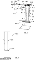
- Fig. 1 shows a perspective view of a scholarpendelan extract 2 according to a first embodiment.
- the engineerpendelan extract 2 has a test probe 4, which is fixed to a cable assembly 6.
- the cable assembly 6 has four cables 8.1 to 8.4. Viewed in an acceleration direction B, the cables 8.1 and 8.4 as well as 8.2 and 8.3 each span one V. The ropes 8.1 to 8.4 are each fixed to the test probe 4. The cables each have a standard length I N.
- the test probe 4 is arranged on a first linear drive 10.
- the linear drive 10 has a rail 12 and a carriage 14 guided on the rail 12.
- a wedge 16 is arranged, which bears against the test probe 4. If the carriage 14 is accelerated in the direction of acceleration B, the wedge 16 acts with the test probe 4 and accelerates the test probe 4.
- the ropes 8.1 to 8.4 are fixed at their upper end to suspensions, which are each formed as a drive slide 18.1 to 18.4.
- the drive carriages 18.1, 18.2 run on a first drive rail 20 of a linear drive 22.
- the drive carriages 18.3, 18.4 run on a second drive rail 24 of a linear drive 26.
- the linear drives 10, 22 and 26 or the drive carriages 14 and 18.1 to 18.4 are controlled by a control 28 controlled.
- the controller 28 are current location information of the respective drive carriage 14 and 18.1 to 18.4 transmitted. As a result, an exact position-time control can be made.
- one drive carriage per track 20, 24 may be provided.
- the braking of the drive carriage 18.1 to 18.4 take in the illustrated embodiment, hydraulic shock absorbers 30.1 to 30.4 which are arranged on the drive rails 20, 24.
- each drive slide 18.1 to 18.4 each assigned its own shock absorber 30.1 to 30.4.
- the drive carriages 18.1 to 18.4 can thus be designed and the shock absorbers 30.1 to 30.4 arranged such that only one shock absorber 30.1 to 30.4 cooperates with only one drive carriage 18.1 to 18.4 each. This can be realized for example via corresponding projections on the drive carriage 18.1 to 18.4.
- Fig. 2 shows a test pendulum assembly 102 of the prior art.
- a test probe 104 is disposed on a rope assembly 106 of standard length L N.
- the test probe 104 is raised at strained ropes of the cable assembly 106 to a certain height and released to carry out the test.
- the force of gravity accelerates the test probe 104 and, at the time shown when it is intended to collide with the body to be tested, achieves its predetermined speed, which is always the same due to the rope length and the given pendulum height.
- Fig. 3 shows the sketchpendelan extract 2 Fig. 1 at a time after triggering.
- test probe 4 In contrast to Fig. 1 the test probe 4 has detached from the carriage 14 and moves forward at a speed v P.
- the drive carriages 18.1 to 18.4 move forward to a point of impact of the test probe 4 at the same speed v P.
- the test probe 4 thus has the same kinetic state as the test probe 104 in FIG Fig. 2 .
- the Accelerating the test probe 104 is necessary.
- the traversed space of the test probe 4 is much lower than that of the test probe 104 of the prior art, so that a risk of collision of the test probe 4 is reduced with operating personnel.
- the drive carriage 14 is accelerated against the acceleration direction B corresponding to the probe velocity vector v P to avoid collision of the probe 4 after rebounding from a crash test dummy (not shown) and thereby a danger of damage.
- Fig. 4 shows a second embodiment of a corresponding admirpendelan extract 2 '.
- the sketchpendelan extract 2 has a rope length L P , which is smaller than the standard rope length L N of educapendelan eleven 2 from the Fig. 1 and 2 ,
- Fig. 5 shows a perspective view of a scholarpendelan extract 2 "according to a third embodiment.
- the engineerpendelan extract 2 has a test probe 4, which is fixed to a cable assembly 6.
- the cable assembly 6 has four cables 8.1 to 8.4. Viewed in an acceleration direction B, the cables 8.1 and 8.4 as well as 8.2 and 8.3 each span one V. The ropes 8.1 to 8.4 are each fixed to the test probe 4. The cables each have a standard length I N.
- two ropes 8.5 and 8.6 are set crosswise to the test probe 4, so in the direction of acceleration B looking the rope 8.5 from top left to bottom right and the rope 8.6 from top right to bottom left is.
- the ropes 8.5 and 8.6 prevent rolling of the test pendulum 2 about the longitudinal axis, which in the present case is parallel to the direction of acceleration B.
- the test probe 4 is arranged on a first linear drive 10.
- the linear drive 10 has a rail 12 and a carriage 14 guided on the rail 12.
- a wedge 16 is arranged, which bears against the test probe 4. If the carriage 14 is accelerated in the direction of acceleration B, the wedge 16 acts with the test probe 4 and accelerates the test probe 4.
- the ropes 8.1 to 8.6 are fixed at its upper end to four suspensions, which are each designed as a drive slide 18.1 to 18.4.
- the ropes 8.2 and 8.5 are fixed to the drive carriage 18.2 and the ropes 8.3 and 8.6 to the drive carriage 18.3.
- the drive carriages 18.1, 18.2 run on a first drive rail 20 of a linear drive 22.
- the drive carriages 18.3, 18.4 run on a second drive rail 24 of a linear drive 26.
- the linear drives 10, 22 and 26 or the drive carriages 14 and 18.1 to 18.4 are controlled by a control 28 controlled.
- the controller 28 are current location information of the respective drive carriage 14 and 18.1 to 18.4 transmitted. As a result, an exact position-time control can be made.
- the braking of the drive carriage 18.1 to 18.4 take in the illustrated embodiment hydraulic shock absorbers 30.1 to 30.4, which on the drive rails 20, 24 are arranged.
- each drive slide 18.1 to 18.4 each assigned its own shock absorber 30.1 to 30.4.
- the drive carriages 18.1 to 18.4 can thus be designed and the shock absorbers 30.1 to 30.4 arranged such that only one shock absorber 30.1 to 30.4 cooperates with only one drive carriage 18.1 to 18.4 each. This can be realized for example via corresponding projections on the drive carriage 18.1 to 18.4.
Landscapes
- Physics & Mathematics (AREA)
- General Physics & Mathematics (AREA)
- Chemical & Material Sciences (AREA)
- Life Sciences & Earth Sciences (AREA)
- Engineering & Computer Science (AREA)
- Pathology (AREA)
- Immunology (AREA)
- General Health & Medical Sciences (AREA)
- Biochemistry (AREA)
- Analytical Chemistry (AREA)
- Health & Medical Sciences (AREA)
- Polymers & Plastics (AREA)
- Zoology (AREA)
- Food Science & Technology (AREA)
- Animal Husbandry (AREA)
- Organic Chemistry (AREA)
- Wood Science & Technology (AREA)
- Oil, Petroleum & Natural Gas (AREA)
- Chemical Kinetics & Catalysis (AREA)
- General Chemical & Material Sciences (AREA)
- Combustion & Propulsion (AREA)
- Mechanical Engineering (AREA)
- General Engineering & Computer Science (AREA)
- Investigating Strength Of Materials By Application Of Mechanical Stress (AREA)
Claims (14)
- Dispositif de pendule de test pour exécuter des certifications de dispositifs anthropomorphes d'essai (DAE) (ou « mannequins d'essai de choc »), avec une sonde d'essai (4), qui est disposée suspendue sur un système de câbles (6), les conditions d'essai étant normalisées et une longueur normalisée de câble (IN) étant prévue, le système de câbles (6) comportant une suspension (18.1, 18.2, 18.3, 18.4), un premier entraînement (10) étant prévu pour les accélérations de la sonde d'essai (4), caractérisé en ce que la suspension est constituée comme un chariot d'entraînement (18.1, 18.2, 18.3, 18.4), au moins un deuxième entraînement (22,26) étant prévu pour déplacer le ou les chariots d'entraînement (18.1, 18.2, 18.3, 18.4), avec la sonde d'essai (4).
- Dispositif de pendule de test selon la revendication 1, une commande ou une régulation (28) étant prévue pour actionner le premier entraînement (10) et au moins un deuxième entraînement (22,26).
- Dispositif de pendule de test selon la revendication 1 ou 2, le premier entraînement (10) et/ou au moins un deuxième entraînement (22,26) étant des entraînements linéaires.
- Dispositif de pendule de test selon l'une quelconque des revendications précédentes, le système de câbles (6) comportant au moins quatre câbles (8.1, 8.2, 8.3, 8.4), deux câbles (8.1,8.2) étant disposés dans une première piste (20) et deux câbles (8.3,8.4) dans une deuxième piste (24), des rails d'entraînement (20,24) étant respectivement prévus pour la première piste et pour la deuxième piste.
- Dispositif de pendule de test selon la revendication 4, le système de câbles (6) comportant au moins six câbles (8.1,8.2,8.3,8.4,8.5,8.6), au moins trois câbles (8.1,8.2,8.5) étant disposés dans une première piste (20) et au moins trois câbles (8.3,8.4,8.6) dans une deuxième piste (24), au moins deux des six câbles (8.5,8.6) étant disposés en diagonale sur la sonde d'essai (4).
- Dispositif de pendule de test selon la revendication 4, chaque câble (8.1,8.2,8.3,8.4) comportant une suspension propre.
- Dispositif de pendule de test selon la revendication 5, au moins deux câbles (8.1,8.5) de la première piste (20) et deux câbles (8.4,8.6) de la deuxième piste (24) étant disposés sur une suspension commune.
- Dispositif de pendule de test selon la revendication 6 ou 7, chaque suspension disposant d'un chariot d'entraînement propre (18.1, 18.2, 18.3, 18.4).
- Dispositif de pendule de test selon l'une quelconque des revendications précédentes, des amortisseurs (30.1,30.2) étant disposés sur les rails d'entraînement (20,24).
- Dispositif de pendule de test selon l'une quelconque des revendications précédentes, le système de câbles (6) comportant une longueur de câble (IP) qui correspond à une partie de rupture (IP/IN) de la longueur normalisée de câble (IN).
- Dispositif de pendule de test selon l'une quelconque des revendications précédentes, le système d'entraînement (10) comportant une liaison amovible (14,16) pour la sonde d'essai (4) de telle sorte que la sonde d'essai (4) peut être découplée du premier entraînement (10).
- Procédé de fonctionnement d'un dispositif de pendule de test (2,2',2'') selon l'une quelconque des revendications précédentes, caractérisé en ce que la sonde d'essai (4) est accélérée au moyen du premier entraînement (10) et la suspension (18.1,18.2,18.3,18.4) est accélérée au moyen d'au moins un deuxième entraînement (22,26) à des accélérations respectivement identiques à partir d'un état de repos, la suspension (18.1,18.2,18.3,18.4) étant freinée et la sonde d'essai (4) étant découplée du premier entraînement (10) de telle sorte que la sonde d'essai (4) se balance librement.
- Procédé selon la revendication 12, la suspension (18.1,18.2,18.3,18.4) étant déplacée après le découplage de la sonde d'essai (4) à une vitesse de

- Procédé selon la revendication 12 ou 13, le premier entraînement (10) étant déplacé après le découplage de la sonde d'essai (4) à l'opposé d'une direction d'accélération (B).
Applications Claiming Priority (2)
| Application Number | Priority Date | Filing Date | Title |
|---|---|---|---|
| DE102015006594.7A DE102015006594B4 (de) | 2015-05-21 | 2015-05-21 | Prüfpendelanordnung sowie Verfahren zum Betrieb einer Prüfpendelanordnung |
| PCT/DE2016/000212 WO2016184449A1 (fr) | 2015-05-21 | 2016-05-19 | Dispositif de pendule de test et procédé de fonctionnement d'un dispositif de pendule de test |
Publications (2)
| Publication Number | Publication Date |
|---|---|
| EP3298377A1 EP3298377A1 (fr) | 2018-03-28 |
| EP3298377B1 true EP3298377B1 (fr) | 2019-04-10 |
Family
ID=56561180
Family Applications (1)
| Application Number | Title | Priority Date | Filing Date |
|---|---|---|---|
| EP16745608.6A Active EP3298377B1 (fr) | 2015-05-21 | 2016-05-19 | Dispositif de pendule de test et procédé de fonctionnement d'un dispositif de pendule de test |
Country Status (5)
| Country | Link |
|---|---|
| US (1) | US10436689B2 (fr) |
| EP (1) | EP3298377B1 (fr) |
| DE (1) | DE102015006594B4 (fr) |
| ES (1) | ES2730115T3 (fr) |
| WO (1) | WO2016184449A1 (fr) |
Families Citing this family (3)
| Publication number | Priority date | Publication date | Assignee | Title |
|---|---|---|---|---|
| CN107505115A (zh) * | 2017-10-02 | 2017-12-22 | 国网山西省电力公司电力科学研究院 | 架空配电线路故障指示器跌落试验机 |
| CN110208119B (zh) * | 2019-05-18 | 2022-04-08 | 上海界龙艺术印刷有限公司 | 一种手提袋摆动测试装置 |
| DE102019129721B3 (de) * | 2019-11-05 | 2021-04-01 | ATD-LabTech GmbH | Bremsvorrichtungssystem, Prüfpendelanordnung zur Durchführung von Halszertifizierungen sowie Verfahren zum Betrieb einer Prüfpendelanordnung |
Family Cites Families (10)
| Publication number | Priority date | Publication date | Assignee | Title |
|---|---|---|---|---|
| US1682138A (en) * | 1928-08-28 | Airplane laboratory | ||
| US5922937A (en) * | 1997-08-29 | 1999-07-13 | Lear Corporation | Individual component headform impact test drive |
| FR2839636B1 (fr) * | 2002-05-15 | 2005-02-18 | Cera | Procede de modelisation biomecanique d'une partie du corps d'un animal |
| JP4105988B2 (ja) * | 2003-06-27 | 2008-06-25 | 株式会社ジャスティ | ダミー検定試験装置 |
| US6983638B2 (en) | 2004-03-18 | 2006-01-10 | Lear Corporation | Head restraint evaluator |
| DE102008011356A1 (de) * | 2008-02-27 | 2009-09-03 | Fachhochschule Kaiserslautern | Anordnung zur Simulation von Aufprallunfällen |
| DE102011100370B4 (de) * | 2011-05-03 | 2020-01-09 | Bundesanstalt für Wasserbau | Verfahren zur zerstörungsfreien Untersuchung eines Pollers auf Schäden oder auf dessen Verankerungsfestigkeit |
| US8567230B2 (en) * | 2011-08-22 | 2013-10-29 | Nissan North America, Inc. | Impact test fixture |
| CN202757749U (zh) * | 2012-06-29 | 2013-02-27 | 浙江吉利汽车研究院有限公司杭州分公司 | 一种用于假人足部标定试验的试验台 |
| DE102014002526B4 (de) * | 2014-02-24 | 2023-05-17 | Jens Mehnert | Kollisionsprüfsystem und Verfahren zum Betreiben eines Kollisionsprüfsystems |
-
2015
- 2015-05-21 DE DE102015006594.7A patent/DE102015006594B4/de active Active
-
2016
- 2016-05-19 EP EP16745608.6A patent/EP3298377B1/fr active Active
- 2016-05-19 WO PCT/DE2016/000212 patent/WO2016184449A1/fr active Application Filing
- 2016-05-19 ES ES16745608T patent/ES2730115T3/es active Active
- 2016-05-19 US US15/576,161 patent/US10436689B2/en active Active
Non-Patent Citations (1)
| Title |
|---|
| None * |
Also Published As
| Publication number | Publication date |
|---|---|
| ES2730115T3 (es) | 2019-11-08 |
| DE102015006594A1 (de) | 2016-11-24 |
| EP3298377A1 (fr) | 2018-03-28 |
| DE102015006594B4 (de) | 2020-09-17 |
| US20180136077A1 (en) | 2018-05-17 |
| US10436689B2 (en) | 2019-10-08 |
| WO2016184449A1 (fr) | 2016-11-24 |
Similar Documents
| Publication | Publication Date | Title |
|---|---|---|
| EP2467693B1 (fr) | Procédé permettant de faire fonctionner un dispositif de simulation de collision, équipement additionnel destiné à un dispositif de simulation de collision, et dispositif de simulation de collision comportant ledit équipement additionnel | |
| EP1445075B1 (fr) | méthode pour surveiller un robot et robot muni de moyens de surveillance | |
| DE112009000488B4 (de) | Testsystem mit Strebenanordnung sowie Verfahren | |
| EP3145681B1 (fr) | Procédé permettant d'éviter à un robot de subir des collisions dans une station de travail | |
| EP2781904B1 (fr) | Dispositif de test destiné à la simulation de conditions de conduite | |
| DE102008022546B4 (de) | Vorrichtung und Verfahren zur Optimierung von Mitteln zur Erfassung unmittelbar bevorstehender Kollisionen eines Fahrzeuges | |
| DE102011011018B3 (de) | Pendelfallanlage | |
| EP3298377B1 (fr) | Dispositif de pendule de test et procédé de fonctionnement d'un dispositif de pendule de test | |
| DE19802590A1 (de) | Einrichtung zur Durchführung von Stoßversuchen an Prüfkörpern | |
| EP2378263B1 (fr) | Système et procédé de détermination du centre de gravité de la masse dans des véhicules sur rails | |
| DE19857429A1 (de) | Prüfeinrichtung zur Kraftfahrzeug-Crashsimulation | |
| DE102019129721B3 (de) | Bremsvorrichtungssystem, Prüfpendelanordnung zur Durchführung von Halszertifizierungen sowie Verfahren zum Betrieb einer Prüfpendelanordnung | |
| DE102011103431B4 (de) | Verfahren zur Durchführung von Crash-Schlittenversuchen und Crash-Simulationsanlage | |
| DE3941685A1 (de) | Einrichtung zur fesselung von testobjekten in einem vorgegebenen fesselpunkt | |
| DE102007021666B4 (de) | Vorrichtung zur Erprobung von Maßnahmen für den Kollisionsschutz bei Kraftfahrzeugen | |
| DE102009021686B4 (de) | Crashsimulationsanlage und Crashsimulationsverfahren | |
| DE202015009480U1 (de) | Prüfpendelanordnung | |
| DE102015006507B4 (de) | Prüfpendelanordnung zur Durchführung von Halszertifizierungen sowie Verfahren zum Betrieb einer Prüfpendelanordnung | |
| DE102004029426A1 (de) | Vorrichtung und Verfahren zur Simulierung einer Kollision, insbesondere eines Kraftfahrzeugs mit einem Gegenstand | |
| DE102011051423A1 (de) | Crashsimulationsanlage und Crashsimulationsverfahren | |
| DE102017209837A1 (de) | Crashanlage mit entkoppelter Crashmesswand | |
| DE10106925B4 (de) | Verfahren und Anordnung zur Durchführung eines Fahrzeug-Crash-Tests | |
| EP2091856B1 (fr) | Procédé et dispositif pour déplacer une charge oscillant librement d'un point de départ à un point d'arrivée | |
| DE102005039966B3 (de) | Prüfvorrichtung | |
| DE10220613B4 (de) | Verfahren und Vorrichtung zur Durchführung von sogenannten Crashtests |
Legal Events
| Date | Code | Title | Description |
|---|---|---|---|
| STAA | Information on the status of an ep patent application or granted ep patent |
Free format text: STATUS: THE INTERNATIONAL PUBLICATION HAS BEEN MADE |
|
| PUAI | Public reference made under article 153(3) epc to a published international application that has entered the european phase |
Free format text: ORIGINAL CODE: 0009012 |
|
| STAA | Information on the status of an ep patent application or granted ep patent |
Free format text: STATUS: REQUEST FOR EXAMINATION WAS MADE |
|
| 17P | Request for examination filed |
Effective date: 20171213 |
|
| AK | Designated contracting states |
Kind code of ref document: A1 Designated state(s): AL AT BE BG CH CY CZ DE DK EE ES FI FR GB GR HR HU IE IS IT LI LT LU LV MC MK MT NL NO PL PT RO RS SE SI SK SM TR |
|
| AX | Request for extension of the european patent |
Extension state: BA ME |
|
| DAV | Request for validation of the european patent (deleted) | ||
| DAX | Request for extension of the european patent (deleted) | ||
| GRAP | Despatch of communication of intention to grant a patent |
Free format text: ORIGINAL CODE: EPIDOSNIGR1 |
|
| STAA | Information on the status of an ep patent application or granted ep patent |
Free format text: STATUS: GRANT OF PATENT IS INTENDED |
|
| RIC1 | Information provided on ipc code assigned before grant |
Ipc: G01M 7/08 20060101AFI20181008BHEP Ipc: G01N 3/30 20060101ALI20181008BHEP |
|
| INTG | Intention to grant announced |
Effective date: 20181031 |
|
| GRAS | Grant fee paid |
Free format text: ORIGINAL CODE: EPIDOSNIGR3 |
|
| GRAA | (expected) grant |
Free format text: ORIGINAL CODE: 0009210 |
|
| STAA | Information on the status of an ep patent application or granted ep patent |
Free format text: STATUS: THE PATENT HAS BEEN GRANTED |
|
| AK | Designated contracting states |
Kind code of ref document: B1 Designated state(s): AL AT BE BG CH CY CZ DE DK EE ES FI FR GB GR HR HU IE IS IT LI LT LU LV MC MK MT NL NO PL PT RO RS SE SI SK SM TR |
|
| REG | Reference to a national code |
Ref country code: GB Ref legal event code: FG4D Free format text: NOT ENGLISH |
|
| REG | Reference to a national code |
Ref country code: CH Ref legal event code: EP Ref country code: AT Ref legal event code: REF Ref document number: 1119358 Country of ref document: AT Kind code of ref document: T Effective date: 20190415 |
|
| REG | Reference to a national code |
Ref country code: DE Ref legal event code: R096 Ref document number: 502016004163 Country of ref document: DE |
|
| REG | Reference to a national code |
Ref country code: IE Ref legal event code: FG4D Free format text: LANGUAGE OF EP DOCUMENT: GERMAN |
|
| REG | Reference to a national code |
Ref country code: NL Ref legal event code: MP Effective date: 20190410 |
|
| REG | Reference to a national code |
Ref country code: LT Ref legal event code: MG4D |
|
| PG25 | Lapsed in a contracting state [announced via postgrant information from national office to epo] |
Ref country code: NL Free format text: LAPSE BECAUSE OF FAILURE TO SUBMIT A TRANSLATION OF THE DESCRIPTION OR TO PAY THE FEE WITHIN THE PRESCRIBED TIME-LIMIT Effective date: 20190410 |
|
| PG25 | Lapsed in a contracting state [announced via postgrant information from national office to epo] |
Ref country code: PT Free format text: LAPSE BECAUSE OF FAILURE TO SUBMIT A TRANSLATION OF THE DESCRIPTION OR TO PAY THE FEE WITHIN THE PRESCRIBED TIME-LIMIT Effective date: 20190910 Ref country code: LT Free format text: LAPSE BECAUSE OF FAILURE TO SUBMIT A TRANSLATION OF THE DESCRIPTION OR TO PAY THE FEE WITHIN THE PRESCRIBED TIME-LIMIT Effective date: 20190410 Ref country code: HR Free format text: LAPSE BECAUSE OF FAILURE TO SUBMIT A TRANSLATION OF THE DESCRIPTION OR TO PAY THE FEE WITHIN THE PRESCRIBED TIME-LIMIT Effective date: 20190410 Ref country code: SE Free format text: LAPSE BECAUSE OF FAILURE TO SUBMIT A TRANSLATION OF THE DESCRIPTION OR TO PAY THE FEE WITHIN THE PRESCRIBED TIME-LIMIT Effective date: 20190410 Ref country code: FI Free format text: LAPSE BECAUSE OF FAILURE TO SUBMIT A TRANSLATION OF THE DESCRIPTION OR TO PAY THE FEE WITHIN THE PRESCRIBED TIME-LIMIT Effective date: 20190410 Ref country code: NO Free format text: LAPSE BECAUSE OF FAILURE TO SUBMIT A TRANSLATION OF THE DESCRIPTION OR TO PAY THE FEE WITHIN THE PRESCRIBED TIME-LIMIT Effective date: 20190710 Ref country code: AL Free format text: LAPSE BECAUSE OF FAILURE TO SUBMIT A TRANSLATION OF THE DESCRIPTION OR TO PAY THE FEE WITHIN THE PRESCRIBED TIME-LIMIT Effective date: 20190410 |
|
| PGFP | Annual fee paid to national office [announced via postgrant information from national office to epo] |
Ref country code: CZ Payment date: 20190529 Year of fee payment: 4 |
|
| REG | Reference to a national code |
Ref country code: ES Ref legal event code: FG2A Ref document number: 2730115 Country of ref document: ES Kind code of ref document: T3 Effective date: 20191108 |
|
| PG25 | Lapsed in a contracting state [announced via postgrant information from national office to epo] |
Ref country code: BG Free format text: LAPSE BECAUSE OF FAILURE TO SUBMIT A TRANSLATION OF THE DESCRIPTION OR TO PAY THE FEE WITHIN THE PRESCRIBED TIME-LIMIT Effective date: 20190710 Ref country code: RS Free format text: LAPSE BECAUSE OF FAILURE TO SUBMIT A TRANSLATION OF THE DESCRIPTION OR TO PAY THE FEE WITHIN THE PRESCRIBED TIME-LIMIT Effective date: 20190410 Ref country code: LV Free format text: LAPSE BECAUSE OF FAILURE TO SUBMIT A TRANSLATION OF THE DESCRIPTION OR TO PAY THE FEE WITHIN THE PRESCRIBED TIME-LIMIT Effective date: 20190410 Ref country code: GR Free format text: LAPSE BECAUSE OF FAILURE TO SUBMIT A TRANSLATION OF THE DESCRIPTION OR TO PAY THE FEE WITHIN THE PRESCRIBED TIME-LIMIT Effective date: 20190711 Ref country code: PL Free format text: LAPSE BECAUSE OF FAILURE TO SUBMIT A TRANSLATION OF THE DESCRIPTION OR TO PAY THE FEE WITHIN THE PRESCRIBED TIME-LIMIT Effective date: 20190410 |
|
| REG | Reference to a national code |
Ref country code: CH Ref legal event code: PL |
|
| PG25 | Lapsed in a contracting state [announced via postgrant information from national office to epo] |
Ref country code: IS Free format text: LAPSE BECAUSE OF FAILURE TO SUBMIT A TRANSLATION OF THE DESCRIPTION OR TO PAY THE FEE WITHIN THE PRESCRIBED TIME-LIMIT Effective date: 20190810 |
|
| REG | Reference to a national code |
Ref country code: DE Ref legal event code: R097 Ref document number: 502016004163 Country of ref document: DE |
|
| PG25 | Lapsed in a contracting state [announced via postgrant information from national office to epo] |
Ref country code: LI Free format text: LAPSE BECAUSE OF NON-PAYMENT OF DUE FEES Effective date: 20190531 Ref country code: RO Free format text: LAPSE BECAUSE OF FAILURE TO SUBMIT A TRANSLATION OF THE DESCRIPTION OR TO PAY THE FEE WITHIN THE PRESCRIBED TIME-LIMIT Effective date: 20190410 Ref country code: CH Free format text: LAPSE BECAUSE OF NON-PAYMENT OF DUE FEES Effective date: 20190531 Ref country code: SK Free format text: LAPSE BECAUSE OF FAILURE TO SUBMIT A TRANSLATION OF THE DESCRIPTION OR TO PAY THE FEE WITHIN THE PRESCRIBED TIME-LIMIT Effective date: 20190410 Ref country code: EE Free format text: LAPSE BECAUSE OF FAILURE TO SUBMIT A TRANSLATION OF THE DESCRIPTION OR TO PAY THE FEE WITHIN THE PRESCRIBED TIME-LIMIT Effective date: 20190410 Ref country code: DK Free format text: LAPSE BECAUSE OF FAILURE TO SUBMIT A TRANSLATION OF THE DESCRIPTION OR TO PAY THE FEE WITHIN THE PRESCRIBED TIME-LIMIT Effective date: 20190410 Ref country code: MC Free format text: LAPSE BECAUSE OF FAILURE TO SUBMIT A TRANSLATION OF THE DESCRIPTION OR TO PAY THE FEE WITHIN THE PRESCRIBED TIME-LIMIT Effective date: 20190410 |
|
| REG | Reference to a national code |
Ref country code: BE Ref legal event code: MM Effective date: 20190531 |
|
| PLBE | No opposition filed within time limit |
Free format text: ORIGINAL CODE: 0009261 |
|
| STAA | Information on the status of an ep patent application or granted ep patent |
Free format text: STATUS: NO OPPOSITION FILED WITHIN TIME LIMIT |
|
| PG25 | Lapsed in a contracting state [announced via postgrant information from national office to epo] |
Ref country code: SM Free format text: LAPSE BECAUSE OF FAILURE TO SUBMIT A TRANSLATION OF THE DESCRIPTION OR TO PAY THE FEE WITHIN THE PRESCRIBED TIME-LIMIT Effective date: 20190410 Ref country code: LU Free format text: LAPSE BECAUSE OF NON-PAYMENT OF DUE FEES Effective date: 20190519 |
|
| 26N | No opposition filed |
Effective date: 20200113 |
|
| PG25 | Lapsed in a contracting state [announced via postgrant information from national office to epo] |
Ref country code: TR Free format text: LAPSE BECAUSE OF FAILURE TO SUBMIT A TRANSLATION OF THE DESCRIPTION OR TO PAY THE FEE WITHIN THE PRESCRIBED TIME-LIMIT Effective date: 20190410 |
|
| PG25 | Lapsed in a contracting state [announced via postgrant information from national office to epo] |
Ref country code: IE Free format text: LAPSE BECAUSE OF NON-PAYMENT OF DUE FEES Effective date: 20190519 |
|
| PG25 | Lapsed in a contracting state [announced via postgrant information from national office to epo] |
Ref country code: BE Free format text: LAPSE BECAUSE OF NON-PAYMENT OF DUE FEES Effective date: 20190531 Ref country code: SI Free format text: LAPSE BECAUSE OF FAILURE TO SUBMIT A TRANSLATION OF THE DESCRIPTION OR TO PAY THE FEE WITHIN THE PRESCRIBED TIME-LIMIT Effective date: 20190410 |
|
| PG25 | Lapsed in a contracting state [announced via postgrant information from national office to epo] |
Ref country code: CZ Free format text: LAPSE BECAUSE OF NON-PAYMENT OF DUE FEES Effective date: 20200519 |
|
| PG25 | Lapsed in a contracting state [announced via postgrant information from national office to epo] |
Ref country code: CY Free format text: LAPSE BECAUSE OF FAILURE TO SUBMIT A TRANSLATION OF THE DESCRIPTION OR TO PAY THE FEE WITHIN THE PRESCRIBED TIME-LIMIT Effective date: 20190410 |
|
| PG25 | Lapsed in a contracting state [announced via postgrant information from national office to epo] |
Ref country code: MT Free format text: LAPSE BECAUSE OF FAILURE TO SUBMIT A TRANSLATION OF THE DESCRIPTION OR TO PAY THE FEE WITHIN THE PRESCRIBED TIME-LIMIT Effective date: 20190410 Ref country code: HU Free format text: LAPSE BECAUSE OF FAILURE TO SUBMIT A TRANSLATION OF THE DESCRIPTION OR TO PAY THE FEE WITHIN THE PRESCRIBED TIME-LIMIT; INVALID AB INITIO Effective date: 20160519 |
|
| PG25 | Lapsed in a contracting state [announced via postgrant information from national office to epo] |
Ref country code: MK Free format text: LAPSE BECAUSE OF FAILURE TO SUBMIT A TRANSLATION OF THE DESCRIPTION OR TO PAY THE FEE WITHIN THE PRESCRIBED TIME-LIMIT Effective date: 20190410 |
|
| P01 | Opt-out of the competence of the unified patent court (upc) registered |
Effective date: 20230528 |
|
| PGFP | Annual fee paid to national office [announced via postgrant information from national office to epo] |
Ref country code: IT Payment date: 20230519 Year of fee payment: 8 Ref country code: FR Payment date: 20230525 Year of fee payment: 8 Ref country code: ES Payment date: 20230601 Year of fee payment: 8 Ref country code: DE Payment date: 20230530 Year of fee payment: 8 |
|
| PGFP | Annual fee paid to national office [announced via postgrant information from national office to epo] |
Ref country code: AT Payment date: 20230504 Year of fee payment: 8 |
|
| PGFP | Annual fee paid to national office [announced via postgrant information from national office to epo] |
Ref country code: GB Payment date: 20230529 Year of fee payment: 8 |
|
| REG | Reference to a national code |
Ref country code: DE Ref legal event code: R081 Ref document number: 502016004163 Country of ref document: DE Owner name: ATD-LABTECH GMBH, DE Free format text: FORMER OWNER: PFEIFER, GERHARD, 63867 JOHANNESBERG, DE |