EP3298277B1 - Valve for a reciprocating compressor - Google Patents
Valve for a reciprocating compressor Download PDFInfo
- Publication number
- EP3298277B1 EP3298277B1 EP16726033.0A EP16726033A EP3298277B1 EP 3298277 B1 EP3298277 B1 EP 3298277B1 EP 16726033 A EP16726033 A EP 16726033A EP 3298277 B1 EP3298277 B1 EP 3298277B1
- Authority
- EP
- European Patent Office
- Prior art keywords
- valve
- seat
- guard
- shutter element
- reciprocating compressor
- Prior art date
- Legal status (The legal status is an assumption and is not a legal conclusion. Google has not performed a legal analysis and makes no representation as to the accuracy of the status listed.)
- Active
Links
Images



Classifications
-
- F—MECHANICAL ENGINEERING; LIGHTING; HEATING; WEAPONS; BLASTING
- F16—ENGINEERING ELEMENTS AND UNITS; GENERAL MEASURES FOR PRODUCING AND MAINTAINING EFFECTIVE FUNCTIONING OF MACHINES OR INSTALLATIONS; THERMAL INSULATION IN GENERAL
- F16K—VALVES; TAPS; COCKS; ACTUATING-FLOATS; DEVICES FOR VENTING OR AERATING
- F16K15/00—Check valves
- F16K15/18—Check valves with actuating mechanism; Combined check valves and actuated valves
- F16K15/182—Check valves with actuating mechanism; Combined check valves and actuated valves with actuating mechanism
- F16K15/1821—Check valves with actuating mechanism; Combined check valves and actuated valves with actuating mechanism for check valves with a hinged or pivoted closure member
-
- F—MECHANICAL ENGINEERING; LIGHTING; HEATING; WEAPONS; BLASTING
- F04—POSITIVE - DISPLACEMENT MACHINES FOR LIQUIDS; PUMPS FOR LIQUIDS OR ELASTIC FLUIDS
- F04B—POSITIVE-DISPLACEMENT MACHINES FOR LIQUIDS; PUMPS
- F04B7/00—Piston machines or pumps characterised by having positively-driven valving
- F04B7/02—Piston machines or pumps characterised by having positively-driven valving the valving being fluid-actuated
-
- F—MECHANICAL ENGINEERING; LIGHTING; HEATING; WEAPONS; BLASTING
- F04—POSITIVE - DISPLACEMENT MACHINES FOR LIQUIDS; PUMPS FOR LIQUIDS OR ELASTIC FLUIDS
- F04B—POSITIVE-DISPLACEMENT MACHINES FOR LIQUIDS; PUMPS
- F04B39/00—Component parts, details, or accessories, of pumps or pumping systems specially adapted for elastic fluids, not otherwise provided for in, or of interest apart from, groups F04B25/00 - F04B37/00
- F04B39/08—Actuation of distribution members
-
- F—MECHANICAL ENGINEERING; LIGHTING; HEATING; WEAPONS; BLASTING
- F04—POSITIVE - DISPLACEMENT MACHINES FOR LIQUIDS; PUMPS FOR LIQUIDS OR ELASTIC FLUIDS
- F04B—POSITIVE-DISPLACEMENT MACHINES FOR LIQUIDS; PUMPS
- F04B39/00—Component parts, details, or accessories, of pumps or pumping systems specially adapted for elastic fluids, not otherwise provided for in, or of interest apart from, groups F04B25/00 - F04B37/00
- F04B39/10—Adaptations or arrangements of distribution members
- F04B39/1053—Adaptations or arrangements of distribution members the members being Hoerbigen valves
-
- F—MECHANICAL ENGINEERING; LIGHTING; HEATING; WEAPONS; BLASTING
- F04—POSITIVE - DISPLACEMENT MACHINES FOR LIQUIDS; PUMPS FOR LIQUIDS OR ELASTIC FLUIDS
- F04B—POSITIVE-DISPLACEMENT MACHINES FOR LIQUIDS; PUMPS
- F04B49/00—Control, e.g. of pump delivery, or pump pressure of, or safety measures for, machines, pumps, or pumping installations, not otherwise provided for, or of interest apart from, groups F04B1/00 - F04B47/00
- F04B49/22—Control, e.g. of pump delivery, or pump pressure of, or safety measures for, machines, pumps, or pumping installations, not otherwise provided for, or of interest apart from, groups F04B1/00 - F04B47/00 by means of valves
- F04B49/225—Control, e.g. of pump delivery, or pump pressure of, or safety measures for, machines, pumps, or pumping installations, not otherwise provided for, or of interest apart from, groups F04B1/00 - F04B47/00 by means of valves with throttling valves or valves varying the pump inlet opening or the outlet opening
-
- F—MECHANICAL ENGINEERING; LIGHTING; HEATING; WEAPONS; BLASTING
- F04—POSITIVE - DISPLACEMENT MACHINES FOR LIQUIDS; PUMPS FOR LIQUIDS OR ELASTIC FLUIDS
- F04B—POSITIVE-DISPLACEMENT MACHINES FOR LIQUIDS; PUMPS
- F04B53/00—Component parts, details or accessories not provided for in, or of interest apart from, groups F04B1/00 - F04B23/00 or F04B39/00 - F04B47/00
- F04B53/10—Valves; Arrangement of valves
Definitions
- the subject matter of the present disclosure relates to a valve for a reciprocating compressor.
- Reciprocating compressors equipped with such a valve can be employed in process applications including refineries, petro chemicals, fertilizers, refrigeration and air, as well as in the gas and oil industry, for gas re-injection, gas lift, pipeline gas transmission, gas storage and fuel gas bursting.
- a valve for a reciprocating compressor is known in the state of the art.
- Such valve comprises a seat and a guard, which are substantially planar grills facing each other and placed substantially parallel to each other.
- the seat and the guard both have holes. However, those holes mostly do not overlap.
- a shutter element is placed between the seat and the guard.
- the shutter element is in particular designed so that it can cover the holes on the valve seat. With more detail, the shutter element is pushed against the seat by a set of springs acting between the guard and the shutter element itself. The passage of fluid is thus prevented.
- This valve while being fully automatic (as the opening and closing actions are determined only by the pressure difference between the two sides) disadvantageously precludes the possibility of opening and closing itself on preset conditions other than such pressure difference.
- valve lifter acting on the shutter element and moved by an electromagnetic linear motor.
- Such valve lifter can only open the valve, as it relies on the spring for closing it.
- Document GB 262970 A relates to reciprocating compressors and its object is to provide a means for reducing the output thereof. It has a sheet metal inlet valve closing against a rigid perforated seating. A rigid shut-off valve is forced into closing contact with the inlet valve seating by pressure fluid such as air admitted to the cylinder of a single trunk piston by a pipe-connected inlet.
- a first embodiment of the invention therefore relates to a valve for a reciprocating compressor.
- Such valve comprises a valve body, wherein the valve body comprises a seat and a guard.
- the valve body also defines a valve plane.
- the seat and the guard develop substantially parallel to the valve plane.
- the valve also comprises a shutter element placed between the seat and the guard.
- the shutter element also develops substantially parallel to the valve plane.
- the shutter element is also configured to move between a closed position, in which the passage of fluid is prevented, and an open position, in which the passage of fluid is allowed.
- the valve also comprises a hydraulic apparatus for moving the shutter element at least between the open and the closed positions.
- the hydraulic apparatus comprises a hydraulic circuit having at least a portion integrated in the valve body.
- the hydraulic apparatus comprises a plurality of pistons each being at least partially inserted into a respective housing inside the valve body, each piston also being in contact with the shutter element, wherein a first set of housings is provided inside the seat, a first set of the pistons being each inserted into a respective housing of the first set of housings, and a second set of housings is provided inside the guard, a second set of the pistons being each inserted into a respective housing of the second set of housings, wherein each piston of the first set is opposite to a corresponding piston of the second set with respect to the shutter element.
- valves are much more compact than the electromagnetic actuated type, and provide increased operational flexibility.
- valve of the type generally applied to a cylinder of a reciprocating compressor.
- This valve opens and closes in order to let process fluid in and out of the cylinder.
- the opening and closing of the valve can be actively controlled, i.e. it is a so called "active valve”.
- valve 1 for a reciprocating compressor according to an embodiment of the present invention.
- the valve 1 comprises a valve body 2.
- the valve body 2 is made so that it can be inserted in a cylinder 22 of a reciprocating compressor 21.
- the valve body 2 comprises a seat 3 and a guard 4.
- the seat 3 and the guard 4 define a valve plane "A", which will be used as a reference in the following part of the present disclosure. Indeed, both the seat 3 and the guard 4 develop substantially parallel to the valve plane "A".
- the seat 3 and the guard 4 are both shaped as perforated plates, separated by a gap 5.
- the seat 3 and the guard 4 have each a plurality of holes 13. Each hole 13 is shaped as an arc, being at a predetermined distance from the center and extending along a portion of circumference.
- the holes 13 from the seat 3 generally do not face the holes 13 of the guard 4.
- Other known types of patterns for the holes 13 can be employed in both the seat 3 and the guard 4.
- the seat 3 has an inner face 3a and an outer face 3b.
- the guard 4 has an inner face 4a and an outer face 4b.
- the gap 5 is defined between the inner faces 3a, 4a.
- a shutter element 6 is placed between the seat 3 and the guard 4.
- the shutter element 6 develops substantially parallel to the valve plane "A".
- the shutter element 6 is configured to move between a closed position in which the passage of fluid is prevented and an open position in which the passage of fluid is allowed inside the valve 1.
- the shutter element 6 comprises a grid 14.
- the grid 14 itself comprises a plurality of covers 15 which face the holes 13 on the seat. Therefore, in the closed position, the shutter element is in contact with the seat 3, so that the covers 15 block the holes 13 of the seat 3. In the open position, the shutter element 6 detaches from the seat 3, so that the fluid may flow from the holes 13 of the seat 3, around the covers 15 of the shutter element 6 and to the holes 13 of the guard 4. Also, as it will be clear from a following part of this disclosure, the fluid can also flow in the reverse direction, i.e. from the holes 13 of the guard 4 to the holes 13 of the seat 3.
- the shutter element 6 may comprise, in place of the grid 14, a plurality of distinct rings, arranged so that that can move independently one from each other.
- the shutter element 6 can be configured to move between the closed position and at least an intermediate position. In this way, it is possible to allow the passage of fluid at a reduced rate with respect to a fully open position.
- the valve 1 also comprises a hydraulic apparatus 7 for moving the shutter element 6.
- the hydraulic apparatus 7 can move the shutter element 6 at least between the open and closed positions.
- the hydraulic apparatus 7 comprises a hydraulic circuit 8 of which at least a portion 8a, 8b is integrated in the valve body 8.
- the hydraulic circuit 8 comprises a first portion 8a integrated in the seat 3.
- the hydraulic circuit 8 comprises a second portion 8b which is integrated in the guard 4. More detail on the hydraulic circuit 8 will be given in a following part of the present disclosure.
- the hydraulic apparatus 7 comprises a plurality of pistons 9, 10. Each piston 9, 10 is at least partially inserted into a respective housing 11, 12 inside the valve body 2. Each piston 9, 10 is also placed in contact with the shutter element 6.
- the hydraulic apparatus 7 comprises a first set of pistons 9, each inserted into a respective housing 11 of the first set.
- a second set of housings 12 is provided inside the guard 4.
- the hydraulic apparatus 7 comprises a second set of pistons 10, each inserted into a respective housing 12 of the second set.
- each piston 9 of the first set is placed opposite to a piston 10 of the second set with respect to the shutter element 6.
- each piston 9 of the first set can be joined to a corresponding piston 10 from the second set.
- the pistons 9, 10 may either be constructed as a single piece, or constructed as separate pieces and then joined later.
- first portion 8a of the hydraulic circuit 8 comprises a first main duct 16, which can be placed in fluid communication with an hydraulic actuator 17, as shown for example in figure 1 .
- the hydraulic actuator 17 is not itself part of the valve 1.
- a further embodiment of the present invention may comprise such hydraulic actuator 17 together with a suitable embodiment of the valve 1.
- the first portion 8a also comprises a plurality of first branching ducts 18, each in fluid communication with both the first main duct 16 and with a respective housing 11 of the first set. It is to be noted that, if required by the shape of the seat 3 and by the arrangement of the housings 11 of the first set, the hydraulic circuit 8 may comprise more than one first main duct 16.
- the second portion 8b of the hydraulic circuit 8 comprises a second main duct 19, which can be placed in fluid communication with the hydraulic actuator 17.
- the second portion 8b also comprises a plurality of second branching ducts 20, each in fluid communication with both the second main duct 19 and with a respective housing 12 of the second set. If required by the shape of the guard 4 and by the arrangement of the housings 12 of the second set, the hydraulic circuit 8 may comprise more than one second main duct 19.
Landscapes
- Engineering & Computer Science (AREA)
- General Engineering & Computer Science (AREA)
- Mechanical Engineering (AREA)
- Compressor (AREA)
- Compression-Type Refrigeration Machines With Reversible Cycles (AREA)
- Reduction Or Emphasis Of Bandwidth Of Signals (AREA)
- Lift Valve (AREA)
Description
- The subject matter of the present disclosure relates to a valve for a reciprocating compressor. Reciprocating compressors equipped with such a valve can be employed in process applications including refineries, petro chemicals, fertilizers, refrigeration and air, as well as in the gas and oil industry, for gas re-injection, gas lift, pipeline gas transmission, gas storage and fuel gas bursting.
- A valve for a reciprocating compressor is known in the state of the art. Such valve comprises a seat and a guard, which are substantially planar grills facing each other and placed substantially parallel to each other. The seat and the guard both have holes. However, those holes mostly do not overlap.
- A shutter element is placed between the seat and the guard. The shutter element is in particular designed so that it can cover the holes on the valve seat. With more detail, the shutter element is pushed against the seat by a set of springs acting between the guard and the shutter element itself. The passage of fluid is thus prevented.
- When the pressure from the working fluid increases beyond a predetermined threshold, it can then overcome the elastic force of the springs, thus forcing the valve open and allowing the passage of fluid until the pressure decreases below the acting threshold.
- This valve, while being fully automatic (as the opening and closing actions are determined only by the pressure difference between the two sides) disadvantageously precludes the possibility of opening and closing itself on preset conditions other than such pressure difference.
- In order to overcome such disadvantage the related art provides other devices, such as the one shown in the document
US2012/0260796 . This valve, while retaining the basic construction of the state of the art valve, also comprises a valve lifter acting on the shutter element and moved by an electromagnetic linear motor. Such valve lifter can only open the valve, as it relies on the spring for closing it. - Disadvantageously, such valve is exceedingly complex, thus potentially unreliable. Also, this type of valve needs more space inside the cylinder than the fully automatic version.
- Document
US 6149400 describes a suction valve of the plate-type of construction, comprising a valve plate which is actuated by an electromagnet arranged in a valve catcher. Such design however implies having an electric circuit in close proximity to the process gas, which may itself be inflammable or explosive. Therefore, this kind of valve cannot be safely be employed in such cases. - Document
GB 262970 A - A first embodiment of the invention therefore relates to a valve for a reciprocating compressor. Such valve comprises a valve body, wherein the valve body comprises a seat and a guard. The valve body also defines a valve plane. The seat and the guard develop substantially parallel to the valve plane.
- The valve also comprises a shutter element placed between the seat and the guard. The shutter element also develops substantially parallel to the valve plane. The shutter element is also configured to move between a closed position, in which the passage of fluid is prevented, and an open position, in which the passage of fluid is allowed.
- The valve also comprises a hydraulic apparatus for moving the shutter element at least between the open and the closed positions. The hydraulic apparatus comprises a hydraulic circuit having at least a portion integrated in the valve body. The hydraulic apparatus comprises a plurality of pistons each being at least partially inserted into a respective housing inside the valve body, each piston also being in contact with the shutter element, wherein a first set of housings is provided inside the seat, a first set of the pistons being each inserted into a respective housing of the first set of housings, and a second set of housings is provided inside the guard, a second set of the pistons being each inserted into a respective housing of the second set of housings, wherein each piston of the first set is opposite to a corresponding piston of the second set with respect to the shutter element.
- Such valves are much more compact than the electromagnetic actuated type, and provide increased operational flexibility.
- Further details and specific embodiments will refer to the attached drawings, in which:
-
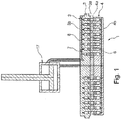
Figure 1 is a side sectional view of a valve for a reciprocating compressor according to an embodiment of the present invention; -
Figure 2 is a perspective sectional view of a detail of the valve offigure 1 ; -
Figure 3 is a detail sectional view of a valve for a reciprocating compressor according to a further embodiment of the present invention; -
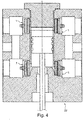
Figure 4 is a sectional view of a cylinder of a reciprocating compressor comprising the valve offigures 1-3 ; and -
Figure 5 is a perspective view of a compressor comprising the cylinder offigure 4 . - The following description of exemplary embodiments refer to the accompanying drawings. The same reference numbers in different drawings identify the same or similar elements. The following detailed description does not limit the invention. Instead, the scope of the invention is defined by the appended claims.
- The following disclosure describes in detail a valve of the type generally applied to a cylinder of a reciprocating compressor. This valve opens and closes in order to let process fluid in and out of the cylinder. Also, the opening and closing of the valve can be actively controlled, i.e. it is a so called "active valve".
- With reference to the attached drawings, with the number 1 is indicated a valve for a reciprocating compressor according to an embodiment of the present invention.
- The valve 1 comprises a
valve body 2. Thevalve body 2 is made so that it can be inserted in acylinder 22 of a reciprocatingcompressor 21. - More in detail, the
valve body 2 comprises aseat 3 and aguard 4. Theseat 3 and theguard 4 define a valve plane "A", which will be used as a reference in the following part of the present disclosure. Indeed, both theseat 3 and theguard 4 develop substantially parallel to the valve plane "A". With reference tofigure 2 , theseat 3 and theguard 4 are both shaped as perforated plates, separated by agap 5. In other words, theseat 3 and theguard 4 have each a plurality ofholes 13. Eachhole 13 is shaped as an arc, being at a predetermined distance from the center and extending along a portion of circumference. Again with reference tofigure 2 , it is to be noted that theholes 13 from theseat 3 generally do not face theholes 13 of theguard 4. Other known types of patterns for theholes 13 can be employed in both theseat 3 and theguard 4. - More in detail, the
seat 3 has aninner face 3a and anouter face 3b. Theguard 4 has aninner face 4a and anouter face 4b. Thegap 5 is defined between theinner faces - A
shutter element 6 is placed between theseat 3 and theguard 4. Theshutter element 6 develops substantially parallel to the valve plane "A". Theshutter element 6 is configured to move between a closed position in which the passage of fluid is prevented and an open position in which the passage of fluid is allowed inside the valve 1. - With additional detail, the
shutter element 6 comprises agrid 14. Thegrid 14 itself comprises a plurality ofcovers 15 which face theholes 13 on the seat. Therefore, in the closed position, the shutter element is in contact with theseat 3, so that thecovers 15 block theholes 13 of theseat 3. In the open position, theshutter element 6 detaches from theseat 3, so that the fluid may flow from theholes 13 of theseat 3, around thecovers 15 of theshutter element 6 and to theholes 13 of theguard 4. Also, as it will be clear from a following part of this disclosure, the fluid can also flow in the reverse direction, i.e. from theholes 13 of theguard 4 to theholes 13 of theseat 3. - In an alternative embodiment, not shown in the drawings, the
shutter element 6 may comprise, in place of thegrid 14, a plurality of distinct rings, arranged so that that can move independently one from each other. - In a further embodiment of the invention, the
shutter element 6 can be configured to move between the closed position and at least an intermediate position. In this way, it is possible to allow the passage of fluid at a reduced rate with respect to a fully open position. - The valve 1 also comprises a hydraulic apparatus 7 for moving the
shutter element 6. Specifically, the hydraulic apparatus 7 can move theshutter element 6 at least between the open and closed positions. In particular, the hydraulic apparatus 7 comprises ahydraulic circuit 8 of which at least aportion valve body 8. In detail, thehydraulic circuit 8 comprises afirst portion 8a integrated in theseat 3. Similarly, thehydraulic circuit 8 comprises asecond portion 8b which is integrated in theguard 4. More detail on thehydraulic circuit 8 will be given in a following part of the present disclosure. - The hydraulic apparatus 7 comprises a plurality of
pistons piston respective housing valve body 2. Eachpiston shutter element 6. - With additional detail, a first set of
housings 11 is provided inside theseat 3. The hydraulic apparatus 7 comprises a first set ofpistons 9, each inserted into arespective housing 11 of the first set. - A second set of
housings 12 is provided inside theguard 4. The hydraulic apparatus 7 comprises a second set ofpistons 10, each inserted into arespective housing 12 of the second set. - It is to be noted that, according to the embodiment of invention shown in
figure 2 , eachpiston 9 of the first set is placed opposite to apiston 10 of the second set with respect to theshutter element 6. - Indeed, as shown in a further embodiment of the invention, each
piston 9 of the first set can be joined to acorresponding piston 10 from the second set. With more detail, in this case thepistons - In detail, the aforementioned
first portion 8a of thehydraulic circuit 8 comprises a firstmain duct 16, which can be placed in fluid communication with anhydraulic actuator 17, as shown for example infigure 1 . Thehydraulic actuator 17 is not itself part of the valve 1. However, a further embodiment of the present invention may comprise suchhydraulic actuator 17 together with a suitable embodiment of the valve 1. - The
first portion 8a also comprises a plurality of first branchingducts 18, each in fluid communication with both the firstmain duct 16 and with arespective housing 11 of the first set. It is to be noted that, if required by the shape of theseat 3 and by the arrangement of thehousings 11 of the first set, thehydraulic circuit 8 may comprise more than one firstmain duct 16. - Also, the
second portion 8b of thehydraulic circuit 8 comprises a secondmain duct 19, which can be placed in fluid communication with thehydraulic actuator 17. Thesecond portion 8b also comprises a plurality of second branchingducts 20, each in fluid communication with both the secondmain duct 19 and with arespective housing 12 of the second set. If required by the shape of theguard 4 and by the arrangement of thehousings 12 of the second set, thehydraulic circuit 8 may comprise more than one secondmain duct 19. - Reference throughout the specification to "one embodiment" or "an embodiment" means that a particular feature, structure, or characteristic described in connection with an embodiment is included in at least one embodiment of the subject matter disclosed. Thus, the appearance of the phrases "in one embodiment" or "in an embodiment" in various places throughout the specification is not necessarily referring to the same embodiment. Further, the particular features, structures or characteristics may be combined in any suitable manner in one or more embodiments.
Claims (5)
- A valve (1) for a reciprocating compressor (21), comprising a valve body (2) comprising a seat (3) and a guard (4) and defining a valve plane (A), the seat (3) and the guard (4) developing substantially parallel to the valve plane (A); a shutter element (6) placed between the seat (3) and the guard (4) and developing substantially parallel to the valve plane (A), the shutter element (6) being configured to move between a closed position in which the passage of fluid is prevented and an open position in which the passage of fluid is allowed; an hydraulic apparatus (7) for moving the shutter element (6) at least between the open and the closed position, the hydraulic apparatus (7) comprising an hydraulic circuit (8) having at least a portion (8a, 8b) integrated in the valve body (2);
characterized in that
the hydraulic circuit (8) comprises a first portion (8a) integrated in the seat (3) and a second portion (8b) integrated in the guard (4); and the hydraulic apparatus (7) further comprises a first set of housings (11) provided inside the seat (3), a first set of the pistons (9) being each at least partially inserted into a respective housing (11) of the first set of housings (11), and a second set of housings (12) provided inside the guard (4), a second set of the pistons (10) being each at least partially inserted into a respective housing (12) of the second set of housings (12);
wherein each of the pistons (9,10) is in contact with the shutter element (6); and
wherein each piston (9) of the first set is opposite to a corresponding piston (10) of the second set with respect to the shutter element (6). - The valve (1) according to claim 1, wherein each piston (9) of the first set is joined to a corresponding piston (10) from the second set.
- The valve (1) according to claim 1 or 2, wherein the shutter element (6) is configured to also move between the closed position and at least an intermediate position allowing the passage of fluid at a reduced rate with respect to the open position.
- A cylinder (22) for a reciprocating compressor (21), the cylinder (22) comprising at least a valve (1) according to any one of claims 1 to 3.
- A reciprocating compressor (21) comprising a valve (1) according to any one of the claims from 1 to 3.
Priority Applications (1)
| Application Number | Priority Date | Filing Date | Title |
|---|---|---|---|
| PL16726033T PL3298277T3 (en) | 2015-05-22 | 2016-05-17 | Valve for a reciprocating compressor |
Applications Claiming Priority (2)
| Application Number | Priority Date | Filing Date | Title |
|---|---|---|---|
| ITUB2015A000797A ITUB20150797A1 (en) | 2015-05-22 | 2015-05-22 | VALVE FOR AN ALTERNATIVE COMPRESSOR |
| PCT/EP2016/061013 WO2016188800A1 (en) | 2015-05-22 | 2016-05-17 | Valve for a reciprocating compressor |
Publications (2)
| Publication Number | Publication Date |
|---|---|
| EP3298277A1 EP3298277A1 (en) | 2018-03-28 |
| EP3298277B1 true EP3298277B1 (en) | 2020-07-01 |
Family
ID=53765453
Family Applications (1)
| Application Number | Title | Priority Date | Filing Date |
|---|---|---|---|
| EP16726033.0A Active EP3298277B1 (en) | 2015-05-22 | 2016-05-17 | Valve for a reciprocating compressor |
Country Status (6)
| Country | Link |
|---|---|
| US (1) | US10215295B2 (en) |
| EP (1) | EP3298277B1 (en) |
| ES (1) | ES2819905T3 (en) |
| IT (1) | ITUB20150797A1 (en) |
| PL (1) | PL3298277T3 (en) |
| WO (1) | WO2016188800A1 (en) |
Families Citing this family (7)
| Publication number | Priority date | Publication date | Assignee | Title |
|---|---|---|---|---|
| JP7165670B6 (en) * | 2017-03-27 | 2023-08-18 | ブルクハルト コンプレッション アーゲー | Valve closure for piston compressor valve and method for operating the valve closure |
| EP3601799B1 (en) * | 2017-03-27 | 2023-01-11 | Burckhardt Compression AG | Piston compressor valve and method for operating same |
| JP7362637B2 (en) * | 2018-03-08 | 2023-10-17 | ブルクハルト コンプレッション アーゲー | Plate valve and its operating method |
| CN208605661U (en) * | 2018-05-14 | 2019-03-15 | 讯凯国际股份有限公司 | Control valve |
| IT201800006557A1 (en) * | 2018-06-21 | 2019-12-21 | RECIPROCATING COMPRESSOR VALVE BODY MADE BY ADDITIVE MANUFACTURING / ALTERNATIVE COMPRESSION VALVE BODY OBTAINED WITH ADDITIVE CONSTRUCTION TECHNIQUE | |
| US11732707B2 (en) * | 2021-06-08 | 2023-08-22 | Siemens Energy, Inc. | Inlet valve system |
| CN116591935B (en) * | 2023-05-24 | 2025-11-18 | 沈阳工业大学 | A rotary cup-type exhaust valve for full-process control of reciprocating compressors |
Family Cites Families (26)
| Publication number | Priority date | Publication date | Assignee | Title |
|---|---|---|---|---|
| GB262970A (en) * | 1926-01-15 | 1926-12-23 | Belliss And Morcom Ltd | Improvements in reciprocating air compressors |
| JPS6075782A (en) * | 1983-09-30 | 1985-04-30 | Japan Steel Works Ltd:The | Stepless capacity adjuster for reciprocating compressor |
| AT398809B (en) * | 1987-07-01 | 1995-02-27 | Hoerbiger Ventilwerke Ag | DISC VALVE FOR A COMPRESSOR |
| AT396002B (en) * | 1987-10-28 | 1993-05-25 | Hoerbiger Ventilwerke Ag | DISC VALVE FOR COMPRESSORS |
| US4852608A (en) * | 1988-10-04 | 1989-08-01 | Dresser-Rand Company | Fluid control valve |
| AT391928B (en) * | 1989-09-27 | 1990-12-27 | Hoerbiger Ventilwerke Ag | VALVE, ESPECIALLY FOR COMPRESSORS |
| AT403835B (en) * | 1994-07-29 | 1998-05-25 | Hoerbiger Ventilwerke Ag | DEVICE AND METHOD FOR INFLUENCING A VALVE |
| EP0853728B1 (en) | 1995-10-03 | 2002-05-08 | Maschinenfabrik Sulzer-Burckhardt AG | Method and device for an intake valve of plate-like construction |
| CN1395656A (en) * | 2000-01-11 | 2003-02-05 | 科尔泰克工业产品公司 | Shaped flat valve |
| US7356231B2 (en) | 2005-02-28 | 2008-04-08 | 3M Innovative Properties Company | Composite polymer fibers |
| US7651069B2 (en) | 2006-05-26 | 2010-01-26 | General Electric Company | Electromagnetic actuators |
| AT504695B1 (en) * | 2006-12-22 | 2008-12-15 | Hoerbiger Kompressortech Hold | SUCTION VALVE WITH REMOVABLE GRIPPER |
| US8048815B2 (en) | 2007-12-12 | 2011-11-01 | Kubota Research, Inc. | Composite article and method of manufacture |
| US8047166B2 (en) | 2008-04-02 | 2011-11-01 | General Electric Company | Electric valve actuation system |
| US20100140519A1 (en) | 2008-12-04 | 2010-06-10 | General Electric Company | Electromagnetic actuators |
| AT509878B1 (en) * | 2010-12-15 | 2011-12-15 | Hoerbiger Kompressortech Hold | SUCTION VALVE WITH REMOVABLE GRIPPER |
| AT511238B1 (en) | 2011-04-14 | 2013-03-15 | Hoerbiger Kompressortech Hold | PISTON COMPRESSORS WITH CONVEYOR RANGE CONTROL |
| ITCO20110072A1 (en) | 2011-12-22 | 2013-06-23 | Nuovo Pignone Spa | VALVES WITH VALVE VALVE END CONNECTED TO THE ACTUAL COUNTERS AND RELATIVE METHODS |
| ITCO20110071A1 (en) | 2011-12-22 | 2013-06-23 | Nuovo Pignone Spa | ALTERNATIVE COMPRESSORS HAVING TIMED VALVES AND RELATED METHODS |
| ITMI20112391A1 (en) | 2011-12-27 | 2013-06-28 | Nuovo Pignone Spa | DEVICES AND METHODS TO IMPLEMENT VALVES |
| ITMI20112393A1 (en) | 2011-12-27 | 2013-06-28 | Nuovo Pignone Spa | ROTO-TRANSLATING ACTIVATED ROTARY VALVES FOR ALTERNATIVE COMPRESSORS AND RELATED METHODS |
| ITMI20112396A1 (en) | 2011-12-27 | 2013-06-28 | Nuovo Pignone Spa | ROTARY VALVES WITH CLOSING PROFILES BETWEEN STATOR AND ROTOR AND RELATED METHODS |
| ITMI20112392A1 (en) | 2011-12-27 | 2013-06-28 | Nuovo Pignone Spa | EQUIPMENT AND METHODS FOR IMPLEMENTING VALVES |
| ITFI20120048A1 (en) * | 2012-03-08 | 2013-09-09 | Nuovo Pignone Srl | "AUTOMATIC VALVE WITH A SPRING HOLDER RING" |
| AT512790B1 (en) * | 2012-11-15 | 2013-11-15 | Hoerbiger Kompressortech Hold | Cylinder head for a reciprocating compressor |
| AT514580B1 (en) * | 2013-11-21 | 2015-02-15 | Hoerbiger Kompressortech Hold | Lifting gripper for a valve element of a compressor valve |
-
2015
- 2015-05-22 IT ITUB2015A000797A patent/ITUB20150797A1/en unknown
-
2016
- 2016-05-17 EP EP16726033.0A patent/EP3298277B1/en active Active
- 2016-05-17 US US15/576,060 patent/US10215295B2/en active Active
- 2016-05-17 PL PL16726033T patent/PL3298277T3/en unknown
- 2016-05-17 ES ES16726033T patent/ES2819905T3/en active Active
- 2016-05-17 WO PCT/EP2016/061013 patent/WO2016188800A1/en not_active Ceased
Non-Patent Citations (1)
| Title |
|---|
| None * |
Also Published As
| Publication number | Publication date |
|---|---|
| US20180163881A1 (en) | 2018-06-14 |
| PL3298277T3 (en) | 2020-12-14 |
| US10215295B2 (en) | 2019-02-26 |
| ES2819905T3 (en) | 2021-04-19 |
| ITUB20150797A1 (en) | 2016-11-22 |
| WO2016188800A1 (en) | 2016-12-01 |
| EP3298277A1 (en) | 2018-03-28 |
Similar Documents
| Publication | Publication Date | Title |
|---|---|---|
| US10215295B2 (en) | Valve for a reciprocating compressor | |
| JP2012528289A (en) | Short stroke flow control valve | |
| CN104895859B (en) | The valve module of function is kept with load | |
| US20150252909A1 (en) | Low head to stem ratio poppet valve | |
| US9279433B2 (en) | Poppet valve assembly for controlling a pneumatic actuator | |
| JP5676984B2 (en) | Shut-off valve | |
| EP3129660B1 (en) | Servo valve | |
| US10781935B2 (en) | Solenoid valve | |
| EP2580503B1 (en) | Face sealing annular valve | |
| JP5710183B2 (en) | Pilot operated bidirectional solenoid valve | |
| US10865892B2 (en) | Subsea valve with non-circular sliding metal seals | |
| KR101852833B1 (en) | Multi-stage poppet valve | |
| KR101790959B1 (en) | Diaphragm type valve for cryogenic | |
| EP2425134B1 (en) | Compressor valve arrangement | |
| WO2013018145A1 (en) | Face sealing annular valve for a fluid-working machine | |
| EP3193054B1 (en) | Check valves | |
| EP2716945A1 (en) | Flow trim for a valve | |
| CN106764001A (en) | Air by-pass valve | |
| JP2021050780A (en) | Annular valve and working fluid machine | |
| EP3298308B1 (en) | Poppet valve | |
| EP3144506B1 (en) | Fluid metering valve | |
| US20190211930A1 (en) | Flat gasket | |
| JP7040004B2 (en) | Relief valve | |
| CN112413173A (en) | Flow path switching valve | |
| KR20240168623A (en) | Driving cylinder |
Legal Events
| Date | Code | Title | Description |
|---|---|---|---|
| STAA | Information on the status of an ep patent application or granted ep patent |
Free format text: STATUS: THE INTERNATIONAL PUBLICATION HAS BEEN MADE |
|
| PUAI | Public reference made under article 153(3) epc to a published international application that has entered the european phase |
Free format text: ORIGINAL CODE: 0009012 |
|
| STAA | Information on the status of an ep patent application or granted ep patent |
Free format text: STATUS: REQUEST FOR EXAMINATION WAS MADE |
|
| 17P | Request for examination filed |
Effective date: 20171222 |
|
| AK | Designated contracting states |
Kind code of ref document: A1 Designated state(s): AL AT BE BG CH CY CZ DE DK EE ES FI FR GB GR HR HU IE IS IT LI LT LU LV MC MK MT NL NO PL PT RO RS SE SI SK SM TR |
|
| AX | Request for extension of the european patent |
Extension state: BA ME |
|
| DAV | Request for validation of the european patent (deleted) | ||
| DAX | Request for extension of the european patent (deleted) | ||
| GRAP | Despatch of communication of intention to grant a patent |
Free format text: ORIGINAL CODE: EPIDOSNIGR1 |
|
| STAA | Information on the status of an ep patent application or granted ep patent |
Free format text: STATUS: GRANT OF PATENT IS INTENDED |
|
| INTG | Intention to grant announced |
Effective date: 20191210 |
|
| RAP1 | Party data changed (applicant data changed or rights of an application transferred) |
Owner name: NUOVO PIGNONE TECNOLOGIE - S.R.L. |
|
| GRAS | Grant fee paid |
Free format text: ORIGINAL CODE: EPIDOSNIGR3 |
|
| GRAA | (expected) grant |
Free format text: ORIGINAL CODE: 0009210 |
|
| STAA | Information on the status of an ep patent application or granted ep patent |
Free format text: STATUS: THE PATENT HAS BEEN GRANTED |
|
| AK | Designated contracting states |
Kind code of ref document: B1 Designated state(s): AL AT BE BG CH CY CZ DE DK EE ES FI FR GB GR HR HU IE IS IT LI LT LU LV MC MK MT NL NO PL PT RO RS SE SI SK SM TR |
|
| REG | Reference to a national code |
Ref country code: CH Ref legal event code: EP Ref country code: AT Ref legal event code: REF Ref document number: 1286428 Country of ref document: AT Kind code of ref document: T Effective date: 20200715 |
|
| REG | Reference to a national code |
Ref country code: IE Ref legal event code: FG4D |
|
| REG | Reference to a national code |
Ref country code: DE Ref legal event code: R096 Ref document number: 602016039107 Country of ref document: DE |
|
| REG | Reference to a national code |
Ref country code: NL Ref legal event code: FP |
|
| REG | Reference to a national code |
Ref country code: LT Ref legal event code: MG4D |
|
| PG25 | Lapsed in a contracting state [announced via postgrant information from national office to epo] |
Ref country code: BG Free format text: LAPSE BECAUSE OF FAILURE TO SUBMIT A TRANSLATION OF THE DESCRIPTION OR TO PAY THE FEE WITHIN THE PRESCRIBED TIME-LIMIT Effective date: 20201001 |
|
| REG | Reference to a national code |
Ref country code: AT Ref legal event code: MK05 Ref document number: 1286428 Country of ref document: AT Kind code of ref document: T Effective date: 20200701 |
|
| PG25 | Lapsed in a contracting state [announced via postgrant information from national office to epo] |
Ref country code: CZ Free format text: LAPSE BECAUSE OF FAILURE TO SUBMIT A TRANSLATION OF THE DESCRIPTION OR TO PAY THE FEE WITHIN THE PRESCRIBED TIME-LIMIT Effective date: 20200701 Ref country code: GR Free format text: LAPSE BECAUSE OF FAILURE TO SUBMIT A TRANSLATION OF THE DESCRIPTION OR TO PAY THE FEE WITHIN THE PRESCRIBED TIME-LIMIT Effective date: 20201002 Ref country code: NO Free format text: LAPSE BECAUSE OF FAILURE TO SUBMIT A TRANSLATION OF THE DESCRIPTION OR TO PAY THE FEE WITHIN THE PRESCRIBED TIME-LIMIT Effective date: 20201001 Ref country code: AT Free format text: LAPSE BECAUSE OF FAILURE TO SUBMIT A TRANSLATION OF THE DESCRIPTION OR TO PAY THE FEE WITHIN THE PRESCRIBED TIME-LIMIT Effective date: 20200701 Ref country code: PT Free format text: LAPSE BECAUSE OF FAILURE TO SUBMIT A TRANSLATION OF THE DESCRIPTION OR TO PAY THE FEE WITHIN THE PRESCRIBED TIME-LIMIT Effective date: 20201102 Ref country code: FI Free format text: LAPSE BECAUSE OF FAILURE TO SUBMIT A TRANSLATION OF THE DESCRIPTION OR TO PAY THE FEE WITHIN THE PRESCRIBED TIME-LIMIT Effective date: 20200701 Ref country code: LT Free format text: LAPSE BECAUSE OF FAILURE TO SUBMIT A TRANSLATION OF THE DESCRIPTION OR TO PAY THE FEE WITHIN THE PRESCRIBED TIME-LIMIT Effective date: 20200701 Ref country code: SE Free format text: LAPSE BECAUSE OF FAILURE TO SUBMIT A TRANSLATION OF THE DESCRIPTION OR TO PAY THE FEE WITHIN THE PRESCRIBED TIME-LIMIT Effective date: 20200701 Ref country code: HR Free format text: LAPSE BECAUSE OF FAILURE TO SUBMIT A TRANSLATION OF THE DESCRIPTION OR TO PAY THE FEE WITHIN THE PRESCRIBED TIME-LIMIT Effective date: 20200701 |
|
| PG25 | Lapsed in a contracting state [announced via postgrant information from national office to epo] |
Ref country code: LV Free format text: LAPSE BECAUSE OF FAILURE TO SUBMIT A TRANSLATION OF THE DESCRIPTION OR TO PAY THE FEE WITHIN THE PRESCRIBED TIME-LIMIT Effective date: 20200701 Ref country code: RS Free format text: LAPSE BECAUSE OF FAILURE TO SUBMIT A TRANSLATION OF THE DESCRIPTION OR TO PAY THE FEE WITHIN THE PRESCRIBED TIME-LIMIT Effective date: 20200701 Ref country code: IS Free format text: LAPSE BECAUSE OF FAILURE TO SUBMIT A TRANSLATION OF THE DESCRIPTION OR TO PAY THE FEE WITHIN THE PRESCRIBED TIME-LIMIT Effective date: 20201101 |
|
| REG | Reference to a national code |
Ref country code: DE Ref legal event code: R097 Ref document number: 602016039107 Country of ref document: DE |
|
| REG | Reference to a national code |
Ref country code: ES Ref legal event code: FG2A Ref document number: 2819905 Country of ref document: ES Kind code of ref document: T3 Effective date: 20210419 |
|
| PG25 | Lapsed in a contracting state [announced via postgrant information from national office to epo] |
Ref country code: IT Free format text: LAPSE BECAUSE OF FAILURE TO SUBMIT A TRANSLATION OF THE DESCRIPTION OR TO PAY THE FEE WITHIN THE PRESCRIBED TIME-LIMIT Effective date: 20200701 Ref country code: EE Free format text: LAPSE BECAUSE OF FAILURE TO SUBMIT A TRANSLATION OF THE DESCRIPTION OR TO PAY THE FEE WITHIN THE PRESCRIBED TIME-LIMIT Effective date: 20200701 Ref country code: RO Free format text: LAPSE BECAUSE OF FAILURE TO SUBMIT A TRANSLATION OF THE DESCRIPTION OR TO PAY THE FEE WITHIN THE PRESCRIBED TIME-LIMIT Effective date: 20200701 Ref country code: SM Free format text: LAPSE BECAUSE OF FAILURE TO SUBMIT A TRANSLATION OF THE DESCRIPTION OR TO PAY THE FEE WITHIN THE PRESCRIBED TIME-LIMIT Effective date: 20200701 Ref country code: DK Free format text: LAPSE BECAUSE OF FAILURE TO SUBMIT A TRANSLATION OF THE DESCRIPTION OR TO PAY THE FEE WITHIN THE PRESCRIBED TIME-LIMIT Effective date: 20200701 |
|
| PLBE | No opposition filed within time limit |
Free format text: ORIGINAL CODE: 0009261 |
|
| STAA | Information on the status of an ep patent application or granted ep patent |
Free format text: STATUS: NO OPPOSITION FILED WITHIN TIME LIMIT |
|
| PG25 | Lapsed in a contracting state [announced via postgrant information from national office to epo] |
Ref country code: AL Free format text: LAPSE BECAUSE OF FAILURE TO SUBMIT A TRANSLATION OF THE DESCRIPTION OR TO PAY THE FEE WITHIN THE PRESCRIBED TIME-LIMIT Effective date: 20200701 |
|
| 26N | No opposition filed |
Effective date: 20210406 |
|
| PG25 | Lapsed in a contracting state [announced via postgrant information from national office to epo] |
Ref country code: SK Free format text: LAPSE BECAUSE OF FAILURE TO SUBMIT A TRANSLATION OF THE DESCRIPTION OR TO PAY THE FEE WITHIN THE PRESCRIBED TIME-LIMIT Effective date: 20200701 |
|
| PG25 | Lapsed in a contracting state [announced via postgrant information from national office to epo] |
Ref country code: SI Free format text: LAPSE BECAUSE OF FAILURE TO SUBMIT A TRANSLATION OF THE DESCRIPTION OR TO PAY THE FEE WITHIN THE PRESCRIBED TIME-LIMIT Effective date: 20200701 |
|
| GBPC | Gb: european patent ceased through non-payment of renewal fee |
Effective date: 20210517 |
|
| PG25 | Lapsed in a contracting state [announced via postgrant information from national office to epo] |
Ref country code: LU Free format text: LAPSE BECAUSE OF NON-PAYMENT OF DUE FEES Effective date: 20210517 Ref country code: MC Free format text: LAPSE BECAUSE OF FAILURE TO SUBMIT A TRANSLATION OF THE DESCRIPTION OR TO PAY THE FEE WITHIN THE PRESCRIBED TIME-LIMIT Effective date: 20200701 |
|
| REG | Reference to a national code |
Ref country code: BE Ref legal event code: MM Effective date: 20210531 |
|
| PG25 | Lapsed in a contracting state [announced via postgrant information from national office to epo] |
Ref country code: IE Free format text: LAPSE BECAUSE OF NON-PAYMENT OF DUE FEES Effective date: 20210517 Ref country code: GB Free format text: LAPSE BECAUSE OF NON-PAYMENT OF DUE FEES Effective date: 20210517 |
|
| PG25 | Lapsed in a contracting state [announced via postgrant information from national office to epo] |
Ref country code: FR Free format text: LAPSE BECAUSE OF NON-PAYMENT OF DUE FEES Effective date: 20210531 |
|
| PG25 | Lapsed in a contracting state [announced via postgrant information from national office to epo] |
Ref country code: BE Free format text: LAPSE BECAUSE OF NON-PAYMENT OF DUE FEES Effective date: 20210531 |
|
| PG25 | Lapsed in a contracting state [announced via postgrant information from national office to epo] |
Ref country code: HU Free format text: LAPSE BECAUSE OF FAILURE TO SUBMIT A TRANSLATION OF THE DESCRIPTION OR TO PAY THE FEE WITHIN THE PRESCRIBED TIME-LIMIT; INVALID AB INITIO Effective date: 20160517 |
|
| PG25 | Lapsed in a contracting state [announced via postgrant information from national office to epo] |
Ref country code: CY Free format text: LAPSE BECAUSE OF FAILURE TO SUBMIT A TRANSLATION OF THE DESCRIPTION OR TO PAY THE FEE WITHIN THE PRESCRIBED TIME-LIMIT Effective date: 20200701 |
|
| P01 | Opt-out of the competence of the unified patent court (upc) registered |
Effective date: 20230526 |
|
| PG25 | Lapsed in a contracting state [announced via postgrant information from national office to epo] |
Ref country code: MK Free format text: LAPSE BECAUSE OF FAILURE TO SUBMIT A TRANSLATION OF THE DESCRIPTION OR TO PAY THE FEE WITHIN THE PRESCRIBED TIME-LIMIT Effective date: 20200701 |
|
| PG25 | Lapsed in a contracting state [announced via postgrant information from national office to epo] |
Ref country code: TR Free format text: LAPSE BECAUSE OF FAILURE TO SUBMIT A TRANSLATION OF THE DESCRIPTION OR TO PAY THE FEE WITHIN THE PRESCRIBED TIME-LIMIT Effective date: 20200701 |
|
| PG25 | Lapsed in a contracting state [announced via postgrant information from national office to epo] |
Ref country code: MT Free format text: LAPSE BECAUSE OF FAILURE TO SUBMIT A TRANSLATION OF THE DESCRIPTION OR TO PAY THE FEE WITHIN THE PRESCRIBED TIME-LIMIT Effective date: 20200701 |
|
| PGFP | Annual fee paid to national office [announced via postgrant information from national office to epo] |
Ref country code: NL Payment date: 20250423 Year of fee payment: 10 |
|
| PGFP | Annual fee paid to national office [announced via postgrant information from national office to epo] |
Ref country code: PL Payment date: 20250423 Year of fee payment: 10 Ref country code: DE Payment date: 20250423 Year of fee payment: 10 |
|
| PGFP | Annual fee paid to national office [announced via postgrant information from national office to epo] |
Ref country code: ES Payment date: 20250602 Year of fee payment: 10 |
|
| PGFP | Annual fee paid to national office [announced via postgrant information from national office to epo] |
Ref country code: CH Payment date: 20250601 Year of fee payment: 10 |