EP3297888B1 - Device for fastening trackside modules to rails - Google Patents
Device for fastening trackside modules to rails Download PDFInfo
- Publication number
- EP3297888B1 EP3297888B1 EP16724378.1A EP16724378A EP3297888B1 EP 3297888 B1 EP3297888 B1 EP 3297888B1 EP 16724378 A EP16724378 A EP 16724378A EP 3297888 B1 EP3297888 B1 EP 3297888B1
- Authority
- EP
- European Patent Office
- Prior art keywords
- rail
- clamps
- brackets
- fastened
- base
- Prior art date
- Legal status (The legal status is an assumption and is not a legal conclusion. Google has not performed a legal analysis and makes no representation as to the accuracy of the status listed.)
- Active
Links
Images


Classifications
-
- E—FIXED CONSTRUCTIONS
- E01—CONSTRUCTION OF ROADS, RAILWAYS, OR BRIDGES
- E01B—PERMANENT WAY; PERMANENT-WAY TOOLS; MACHINES FOR MAKING RAILWAYS OF ALL KINDS
- E01B9/00—Fastening rails on sleepers, or the like
- E01B9/02—Fastening rails, tie-plates, or chairs directly on sleepers or foundations; Means therefor
- E01B9/32—Fastening on steel sleepers with clamp members
-
- B—PERFORMING OPERATIONS; TRANSPORTING
- B61—RAILWAYS
- B61L—GUIDING RAILWAY TRAFFIC; ENSURING THE SAFETY OF RAILWAY TRAFFIC
- B61L1/00—Devices along the route controlled by interaction with the vehicle or train
- B61L1/02—Electric devices associated with track, e.g. rail contacts
-
- B—PERFORMING OPERATIONS; TRANSPORTING
- B61—RAILWAYS
- B61L—GUIDING RAILWAY TRAFFIC; ENSURING THE SAFETY OF RAILWAY TRAFFIC
- B61L1/00—Devices along the route controlled by interaction with the vehicle or train
- B61L1/16—Devices for counting axles; Devices for counting vehicles
-
- B—PERFORMING OPERATIONS; TRANSPORTING
- B61—RAILWAYS
- B61L—GUIDING RAILWAY TRAFFIC; ENSURING THE SAFETY OF RAILWAY TRAFFIC
- B61L3/00—Devices along the route for controlling devices on the vehicle or train, e.g. to release brake or to operate a warning signal
- B61L3/16—Continuous control along the route
- B61L3/22—Continuous control along the route using magnetic or electrostatic induction; using electromagnetic radiation
-
- E—FIXED CONSTRUCTIONS
- E01—CONSTRUCTION OF ROADS, RAILWAYS, OR BRIDGES
- E01B—PERMANENT WAY; PERMANENT-WAY TOOLS; MACHINES FOR MAKING RAILWAYS OF ALL KINDS
- E01B26/00—Tracks or track components not covered by any one of the preceding groups
-
- B—PERFORMING OPERATIONS; TRANSPORTING
- B61—RAILWAYS
- B61L—GUIDING RAILWAY TRAFFIC; ENSURING THE SAFETY OF RAILWAY TRAFFIC
- B61L3/00—Devices along the route for controlling devices on the vehicle or train, e.g. to release brake or to operate a warning signal
- B61L3/16—Continuous control along the route
- B61L3/22—Continuous control along the route using magnetic or electrostatic induction; using electromagnetic radiation
- B61L2003/228—Constructional details
-
- B—PERFORMING OPERATIONS; TRANSPORTING
- B61—RAILWAYS
- B61L—GUIDING RAILWAY TRAFFIC; ENSURING THE SAFETY OF RAILWAY TRAFFIC
- B61L3/00—Devices along the route for controlling devices on the vehicle or train, e.g. to release brake or to operate a warning signal
- B61L3/02—Devices along the route for controlling devices on the vehicle or train, e.g. to release brake or to operate a warning signal at selected places along the route, e.g. intermittent control simultaneous mechanical and electrical control
- B61L3/08—Devices along the route for controlling devices on the vehicle or train, e.g. to release brake or to operate a warning signal at selected places along the route, e.g. intermittent control simultaneous mechanical and electrical control controlling electrically
- B61L3/12—Devices along the route for controlling devices on the vehicle or train, e.g. to release brake or to operate a warning signal at selected places along the route, e.g. intermittent control simultaneous mechanical and electrical control controlling electrically using magnetic or electrostatic induction; using radio waves
- B61L3/126—Constructional details
Definitions
- the invention relates to a device for fastening trackside modules, in particular to a running rail of a railway for rail vehicles.
- the rail may be a grooved rail and/or a Vignole type rail).
- the rail may be one of the two rails of a dual-rail railway for rail vehicles.
- one or more than one of the following devices are examples of trackside modules to be fastened to the rail: wheel and/or vehicle detectors, in particular wheel detector heads, current transformers and communication devices for communication between a vehicle travelling on the rail and the trackside.
- modules of systems i.e. trackside modules
- trackside modules which in the course of a normal operation are located next to a head of a rail. Both at the stage of installation and of normal operation it is required to perform initial and periodical adjustment of the position of the trackside modules in relation to the head of a rail due to the diversity of types of rails used and the wear and tear of rails.
- Movable or fixed (immovable) sections are fastened to the mounted clamps. Movable sections enable a change of the position of trackside modules without the need to use adaptor plates. Furthermore, grooves can be made in the surfaces that are connected. These grooves increase the immunity of screwed items to an undesired change of position during installation and during vibrations. Sections which are immovable (fixed) in relation to the clamps require adaptor plates or positioning nuts.
- US 3,941,338 discloses clamps that are fastened to the base of a rail. The position is set by using nuts which enable changing the position of a trackside module solely in parallel to Y axis (the horizontal axis transverse to the longitudinal Z axis of the rail).
- EP 1 960 603 B1 discloses a solution in which clamps are fastened to the base of a rail.
- One of the clamps consists of a support and two clamp parts which abut on opposite sides on the support. They are assembled in such a way that the upper surface of the support of the clamp contacts the lower surface of the base of the rail, whereas the inner surface of the clamp parts contacts the upper surface of the base of the rail.
- a change of position of the clamp parts (in the direction of or parallel to the Y axis) relative to the support causes a change of the depth to which the support is seated under the base of a rail which makes it possible to change the position of the trackside module in the direction of, or parallel to the Y axis.
- a girder is fastened to the external surface of the clamp (in the plane that is parallel to the plane of symmetry of the web of rail) in such a way that it makes it possible to change the position of the girder in such a manner that the trackside module could be positioned in parallel to the X axis.
- the trackside module could be positioned in parallel to the X axis.
- US 2007/ 0204705 A1 describes a wheel-sensing system having a wheel sensor and a rail mounting platform.
- the system includes a rugged steel rail clamp including two blocks mounted on the base of the rail by a pair of bolt extending under the rail.
- One block is connected to a vertically adjustable mounting bracket for carrying a sensor or other device.
- the mounting bracket includes a platform for the sensor.
- An adapter plate may be added between the mounting bracket and the clamp for installation on lighter or heavier rails.
- FR 2 350 239 A1 discloses a bracket for attaching signaling devices on to railway tracks.
- a pair of U shaped members are clamped onto a base part of the rail. Clamping is achieved by a transverse bolt passing beneath the rail.
- Upwards extending rings provide supports for the signaling members while inwardly directed links provide a resilient bias against the rail.
- the magnetic steel support comprises a supporting frame and a chuck assembly, wherein the supporting frame comprises an adjustment support which is vertically arranged and a sensor installation support which is connected with the adjustment support.
- the adjustment support is connected with the chuck assembly through a locking bolt which is horizontally arranged in a penetrating mode.
- Multiple protrusions and multiple grooves are horizontally arranged on the surface, attached to the adjustment support, of the chuck assembly. The multiple protrusions are matched with the multiple grooves.
- a strip-shaped adjustment hole is vertically formed in the adjustment support, and the locking bolt horizontally penetrates through the adjustment hole to be connected with the chuck assembly.
- JP H08 119105 A relates to the installation of a detector for an alarm for the approach of a train.
- a support seat with a cutout recess having a bearing surface is coupled to one end of the base of a rail.
- the base is clamped with a hook formed on a tightening bolt and the bearing surface, thereby mounting the seat on the rail.
- a screw shaft is vertically erected on and fixed to the top of the seat, and an adjusting fixture with a stepped shaft is screwed to the shaft.
- an inner race in a bearing housing is coupled to and integrated with the shaft.
- the bearing housing is fixed to a bracket for a detector as integral part thereof. The detector, while being kept horizontally via the bearing housing, is supported so as to be movable vertically on the turning motion of the fixture.
- a rail for example a grooved rail and/or a Vignole type rail
- a device for fastening trackside modules, such as, e.g. wheel detector heads, current transformers to a rail, wherein the device has two clamps that are clamped or are to be clamped on the base of the rail with the use of a screw mechanism that is located under the base of the rail. Both clamps are movable.
- a bracket (in particular a vertical bracket) is attached to at least one of the clamps and the trackside module is fastened to the end of the bracket which is located next to the head of the rail.
- the device has two pairs of brackets that are fastened with the use of (in particular threaded) fasteners to the walls and/or surfaces of the clamps. In particular, each pair of brackets is fastened to one of the clamps.
- a first of the pair of brackets is fastened to a first surface of the clamp and a second of the same pair of brackets is fastened to a second surface of the same clamp, wherein the first surface and the second surface are opposite to each other with respect to a central region of the clamp.
- a device for fastening trackside modules, such as, e.g. wheel detector heads and/or current transformers, to a rail having a base and a head, wherein the device comprises two clamps that are to be clamped on the base of the rail with the use of a mechanism that extends under the base of the rail, wherein at least one of the clamps is movable, wherein a pair of brackets is fastened with the use of (in particular threaded) first fasteners to surfaces of each of the clamps, wherein the brackets extend transversely to the longitudinal axis of the rail and at least one upwardly extending section is fastened using (in particular threaded) second fasteners to one of or to each of the outer side surfaces of the brackets, wherein at least one trackside module is to be fastened to an upper end region of the upwardly extending section or to upper end regions of a plurality of the upwardly extending sections.
- at least one upper end region of an upwardly extending section is adapted
- the fixation (fastening) by using at least one of the threaded fasteners mentioned in this description can be realised in connection with an oblong hole, so that it is possible to move and/or re-position a screw or stud bolt (i.e. the part comprising the external thread) within the oblong hole in a direction transverse to the longitudinal axis of the screw or stud bolt.
- a screw or stud bolt i.e. the part comprising the external thread
- each of the clamps may produce the clamping force onto the lower and upper side surfaces of the base of the rail, which clamping force results in the fastening of the device to the rail.
- the brackets fastened to the clamps do not produce a clamping force of this kind, although at least one of the brackets may be in contact with the base of the rail, in particular in contact with the lower side surface of the base of the rail.
- At least one of the clamps may comprise a single clamping piece which is in contact with the lower and the upper side surface of the base of the rail while mounted to the rail.
- the upwardly extending section, or at least one of the upwardly extending sections, that is fastened to one of the brackets can be fastened at the same time to each of the pair of brackets that are fastened to the same clamp.
- the upwardly extending section is fastened to only one of the pair of brackets and that each of two separate upwardly extending sections is fastened to one of the brackets of the same pair of brackets. In the latter case, it is possible that the trackside module is fastened to both of the two separate upwardly extending sections.
- the mounting of the trackside module to the section or sections is easy and re-positioning of the section or sections relative to the clamp is possible without the need to loosen the fixation of the clamp on the rail.
- re-positioning is possible by loosening the fastening (fixation) of either at least one of the brackets on the clamp or of the at least one upwardly extending section on the bracket or brackets or of both.
- the brackets may be positioned perpendicularly to the longitudinal (e.g. Z-) axis of the rail.
- the opposite first and second surfaces of the clamp may extend transverse to the longitudinal axis (e.g. Z-axis) of the rail, to which the device is to be mounted.
- the longitudinal axis of the rail extends in the direction of rail vehicle (e.g. train) movement, i.e. the travel direction.
- Vertical (in particular vertically extending sections or, more generally speaking, upwardly extending) sections are fastened using (in particular threaded) fasteners to the outer side surfaces (the outer sides being the lateral sides if the device is mounted to a running rail) of the brackets.
- Trackside modules are (or can be) fastened to the upper ends of these vertical sections.
- Both movable clamps are connected with one another, e.g. by using fasteners, in particular threaded fasteners, that extend under the base of the rail, in particular in such a way that it is possible to demount the threaded fasteners from each of the clamps.
- At least one of the clamps that are clamped or are to be clamped on the base of the rail may have at least one non-adjustable lug.
- grooves may be formed in the specific mating surfaces of the items whose position in relation to one another is or can be changed by a user during operation.
- the mating surfaces are the surfaces where the clamps come into contact with the brackets. At least one set of these grooves is not or may be not parallel to the others.
- Each of the movable clamps can be the basis for mounting the items that are designed for fastening a trackside module in the required position next to the head of a rail.
- the trackside modules can be located at any side of the head of a rail depending on the requirements for the trackside module that is to be fastened.
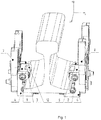
- the device for fastening trackside modules such as, e.g. wheel detector heads and/or current transformers, has two movable clamps 1, 2 with pairs of brackets 3, 4 and 5, 6 respectively which are fastened using threaded fasteners to the walls of the clamps that extend perpendicular to the Z axis of the rail ( Fig.2 ).
- Vertically extending sections 7 and 8 are fastened to the side outer surfaces of the brackets 3 and 4 and 5 and 6 respectively using threaded fasteners and the trackside modules 9 and 10 are fastened to the upper ends of the vertical sections.
- the clamps 1, 2 are connected with each other using threaded fasteners 11 that are led under the base of a rail in such a way that it is possible to demount the threaded fasteners from each of the clamps 1, 2.
- At least one of the clamps 1 or 2 that are clamped on the base of a rail has at least one non-adjustable lug 12.
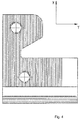
- grooves 5.1 and 6.1 made in the specific mating surfaces of the items that connect with one another and whose position in relation to one another can be changed by a user during operation, i.e. in the mating surfaces of the clamps 1, 2, and the brackets 3 and 4 as well as 5 and 6. At least one of these grooves or sets of grooves is not parallel to the others or other.
- the clamps 1, 2 have surfaces 1.1 and 1.2 and 2.1 and 2.2 which extend perpendicular to the rail axis and which enable mounting of the brackets 3, 4 and 5, 6 and sections 7, 8 on both sides of the head of a rail.
- each of the clamps has a lug which together with the clamp forms an integral whole.
- Such a solution improves the resistance of the device to high vibration load and enables using higher forces that hold the clamps down to the base of a rail. Thanks to the use in the device consistent with the invention of lugs that are integrated with the clamps, as well as independently mounted brackets for a section to which a trackside module is fastened, it is possible to adjust the position and replace the trackside modules after the clamps have been installed on the rail which significantly facilitates the works related to installation and maintenance of the trackside modules.
- Increased resistance of the device to vibrations, in particular vibrations that occur simultaneously along a number of axes, is achieved through the use of grooves that are not parallel to one another and are situated on the mating surfaces of the items that enable changing the position of a trackside module.
- Reduced complexity of the design of the device and thereby lower manufacturing cost has been achieved through standardizing the sections that are connected with the clamps. It is possible to use a set of sections with each of the clamps used.
- the described design enables using typical fasteners in order to guarantee the pressure of the clamps on the base of a rail which contributes to reducing the device manufacturing and maintenance costs. Furthermore, the disclosed design allows for fastening the trackside modules on both sides of the rail at the same time and it is often required in respect of trackside modules forming a part of a rail traffic control system.
- the movable clamps 1, 2 of the device which are clamped on the base of a rail are in the form of supports with brackets 3, 4, 5, 6 that are fastened to the side surfaces of supports. Clamping of the clamps 1, 2 on the base of a rail is possible thanks to the use of threaded fasteners 11 which are led via the clamps 1, 2 and under the base of the rail.
- the brackets 3, 4, 5 and 6 do not touch the base of the rail.
- the purpose of the brackets 3 and 4 is to hold the vertical section 7 together with a trackside module 9 in the required position.
- the change of position of brackets 3, 4 in parallel to the Y axis enables changing the position of the trackside module in parallel to Y axis.
- brackets 5 and 6 The purpose of brackets 5 and 6 is to hold the vertical section 8 together with a trackside module 10 in the required position.
- the change of position of brackets 5, 6 in parallel to the Y axis enables changing the position of the trackside module 10 in parallel to Y axis.
- the change of position of sections 8 in relation to brackets 5, 6 in parallel to X axis makes it possible to change the position of the trackside module 10 in parallel to X axis.
- the items which during the process of setting the operating position of trackside modules 9 and 10 need to change their position and to be re-fastened have grooves 5.1 and 6.1 on their mating surfaces, however some of the grooves are not parallel to the others as shown as an example in Fig. 4 .
- the grooves 5.1 and 6.1 are made in the mating surfaces of clamps 1, 2 and brackets 3, 4 and 5, 6.
Landscapes
- Engineering & Computer Science (AREA)
- Mechanical Engineering (AREA)
- Automation & Control Theory (AREA)
- Architecture (AREA)
- Civil Engineering (AREA)
- Structural Engineering (AREA)
- Physics & Mathematics (AREA)
- Electromagnetism (AREA)
- Connection Of Plates (AREA)
- Machines For Laying And Maintaining Railways (AREA)
- Train Traffic Observation, Control, And Security (AREA)
- Clamps And Clips (AREA)
- Mounting Components In General For Electric Apparatus (AREA)
- Machine Tool Units (AREA)
- Carriers, Traveling Bodies, And Overhead Traveling Cranes (AREA)
- Mutual Connection Of Rods And Tubes (AREA)
Description
- The invention relates to a device for fastening trackside modules, in particular to a running rail of a railway for rail vehicles. For example, the rail may be a grooved rail and/or a Vignole type rail). In particular the rail may be one of the two rails of a dual-rail railway for rail vehicles. In particular, one or more than one of the following devices are examples of trackside modules to be fastened to the rail: wheel and/or vehicle detectors, in particular wheel detector heads, current transformers and communication devices for communication between a vehicle travelling on the rail and the trackside.
- It is necessary to fasten modules of systems (i.e. trackside modules) which in the course of a normal operation are located next to a head of a rail. Both at the stage of installation and of normal operation it is required to perform initial and periodical adjustment of the position of the trackside modules in relation to the head of a rail due to the diversity of types of rails used and the wear and tear of rails.
- It is possible to use clamps that are mounted on to the base of a rail. Movable or fixed (immovable) sections are fastened to the mounted clamps. Movable sections enable a change of the position of trackside modules without the need to use adaptor plates. Furthermore, grooves can be made in the surfaces that are connected. These grooves increase the immunity of screwed items to an undesired change of position during installation and during vibrations. Sections which are immovable (fixed) in relation to the clamps require adaptor plates or positioning nuts.
- A solution is disclosed in
US 7216558 B according to which clamps are mounted on the base of a rail. The position of the clamp is adjusted by using adaptor plates and therefore additional parts need to be supplied to the customer throughout the life cycle of the product. -
US 3,941,338 discloses clamps that are fastened to the base of a rail. The position is set by using nuts which enable changing the position of a trackside module solely in parallel to Y axis (the horizontal axis transverse to the longitudinal Z axis of the rail). - A solution in which the clamps are fastened to a base of a rail and a bracket with a groove is parallel to the rail which enables changing the position of the trackside module in parallel to X axis (the vertical axis) is presented in
DE 974202 . -
EP 1 960 603 B1 - One of the clamps consists of a support and two clamp parts which abut on opposite sides on the support. They are assembled in such a way that the upper surface of the support of the clamp contacts the lower surface of the base of the rail, whereas the inner surface of the clamp parts contacts the upper surface of the base of the rail. A change of position of the clamp parts (in the direction of or parallel to the Y axis) relative to the support causes a change of the depth to which the support is seated under the base of a rail which makes it possible to change the position of the trackside module in the direction of, or parallel to the Y axis. A girder is fastened to the external surface of the clamp (in the plane that is parallel to the plane of symmetry of the web of rail) in such a way that it makes it possible to change the position of the girder in such a manner that the trackside module could be positioned in parallel to the X axis. Like in the solutions referred to above, there are grooves in surfaces of these items which enable changing position in relation to one another.
-
US 2007/ 0204705 A1 describes a wheel-sensing system having a wheel sensor and a rail mounting platform. The system includes a rugged steel rail clamp including two blocks mounted on the base of the rail by a pair of bolt extending under the rail. One block is connected to a vertically adjustable mounting bracket for carrying a sensor or other device. The mounting bracket includes a platform for the sensor. An adapter plate may be added between the mounting bracket and the clamp for installation on lighter or heavier rails. -
FR 2 350 239 A1 -
CN 203 996 281 U1 describes a magnetic steel support for a railway and a rail clamping and installing structure of the magnetic steel support. The magnetic steel support comprises a supporting frame and a chuck assembly, wherein the supporting frame comprises an adjustment support which is vertically arranged and a sensor installation support which is connected with the adjustment support. The adjustment support is connected with the chuck assembly through a locking bolt which is horizontally arranged in a penetrating mode. Multiple protrusions and multiple grooves are horizontally arranged on the surface, attached to the adjustment support, of the chuck assembly. The multiple protrusions are matched with the multiple grooves. A strip-shaped adjustment hole is vertically formed in the adjustment support, and the locking bolt horizontally penetrates through the adjustment hole to be connected with the chuck assembly. -
JP H08 119105 A - It is an object of the invention to provide a device for fastening trackside modules to a rail (for example a grooved rail and/or a Vignole type rail) in order to enable a required mounting and/or operating position of the module(s) to be fastened.
- A device is proposed for fastening trackside modules, such as, e.g. wheel detector heads, current transformers to a rail, wherein the device has two clamps that are clamped or are to be clamped on the base of the rail with the use of a screw mechanism that is located under the base of the rail. Both clamps are movable. A bracket (in particular a vertical bracket) is attached to at least one of the clamps and the trackside module is fastened to the end of the bracket which is located next to the head of the rail. Preferably, the device has two pairs of brackets that are fastened with the use of (in particular threaded) fasteners to the walls and/or surfaces of the clamps. In particular, each pair of brackets is fastened to one of the clamps. In addition or alternatively, a first of the pair of brackets is fastened to a first surface of the clamp and a second of the same pair of brackets is fastened to a second surface of the same clamp, wherein the first surface and the second surface are opposite to each other with respect to a central region of the clamp.
- In particular, a device is proposed for fastening trackside modules, such as, e.g. wheel detector heads and/or current transformers, to a rail having a base and a head, wherein the device comprises two clamps that are to be clamped on the base of the rail with the use of a mechanism that extends under the base of the rail, wherein at least one of the clamps is movable, wherein a pair of brackets is fastened with the use of (in particular threaded) first fasteners to surfaces of each of the clamps, wherein the brackets extend transversely to the longitudinal axis of the rail and at least one upwardly extending section is fastened using (in particular threaded) second fasteners to one of or to each of the outer side surfaces of the brackets, wherein at least one trackside module is to be fastened to an upper end region of the upwardly extending section or to upper end regions of a plurality of the upwardly extending sections. Preferably, at least one upper end region of an upwardly extending section is adapted to be connected and thereby fastened to at least one trackside module, for example by threaded fasteners.
- The fixation (fastening) by using at least one of the threaded fasteners mentioned in this description can be realised in connection with an oblong hole, so that it is possible to move and/or re-position a screw or stud bolt (i.e. the part comprising the external thread) within the oblong hole in a direction transverse to the longitudinal axis of the screw or stud bolt. By moving or re-positioning the screw or stud bolt in this manner, the relative position of the parts to be fixed to each other by the threaded fasteners is changed.
- In particular, each of the clamps may produce the clamping force onto the lower and upper side surfaces of the base of the rail, which clamping force results in the fastening of the device to the rail. In this case, the brackets fastened to the clamps do not produce a clamping force of this kind, although at least one of the brackets may be in contact with the base of the rail, in particular in contact with the lower side surface of the base of the rail. At least one of the clamps may comprise a single clamping piece which is in contact with the lower and the upper side surface of the base of the rail while mounted to the rail.
- Since the clamp produces the mounting force which fixes the device to the rail, it is easy to release the clamp from the rail and remove the clamp or to move the clamp to another position relative to the rail.
- The upwardly extending section, or at least one of the upwardly extending sections, that is fastened to one of the brackets can be fastened at the same time to each of the pair of brackets that are fastened to the same clamp. However, it is also possible alternatively that the upwardly extending section is fastened to only one of the pair of brackets and that each of two separate upwardly extending sections is fastened to one of the brackets of the same pair of brackets. In the latter case, it is possible that the trackside module is fastened to both of the two separate upwardly extending sections.
- Since the at least one upwardly extending section is fastened to the bracket or brackets, the mounting of the trackside module to the section or sections is easy and re-positioning of the section or sections relative to the clamp is possible without the need to loosen the fixation of the clamp on the rail. In particular, re-positioning is possible by loosening the fastening (fixation) of either at least one of the brackets on the clamp or of the at least one upwardly extending section on the bracket or brackets or of both.
- On the other hand, it is also possible to loosen the fixation of the clamp on the rail while the at least one upwardly extending section is continuously fastened (i.e. fixed) to the bracket or brackets.
- The brackets may be positioned perpendicularly to the longitudinal (e.g. Z-) axis of the rail. In addition or alternatively, the opposite first and second surfaces of the clamp may extend transverse to the longitudinal axis (e.g. Z-axis) of the rail, to which the device is to be mounted. The longitudinal axis of the rail extends in the direction of rail vehicle (e.g. train) movement, i.e. the travel direction.
- Vertical (in particular vertically extending sections or, more generally speaking, upwardly extending) sections are fastened using (in particular threaded) fasteners to the outer side surfaces (the outer sides being the lateral sides if the device is mounted to a running rail) of the brackets. Trackside modules are (or can be) fastened to the upper ends of these vertical sections. Both movable clamps are connected with one another, e.g. by using fasteners, in particular threaded fasteners, that extend under the base of the rail, in particular in such a way that it is possible to demount the threaded fasteners from each of the clamps. At least one of the clamps that are clamped or are to be clamped on the base of the rail may have at least one non-adjustable lug.
- According to an embodiment of the device, grooves may be formed in the specific mating surfaces of the items whose position in relation to one another is or can be changed by a user during operation. The mating surfaces are the surfaces where the clamps come into contact with the brackets. At least one set of these grooves is not or may be not parallel to the others.
- Each of the movable clamps can be the basis for mounting the items that are designed for fastening a trackside module in the required position next to the head of a rail. The trackside modules can be located at any side of the head of a rail depending on the requirements for the trackside module that is to be fastened.
- An example of an embodiment of the invention is shown in the attached Figures:
- Fig.1
- shows an isometric view of a device for fastening trackside modules to a rail in their actual and/or required position of use on a rail (operating position) but without trackside modules,
- Fig. 2
- shows the device with trackside modules fastened in its actual position of use (but without a rail being shown),
- Fig. 3
- shows the device in its actual position of use from the side of the base of a rail,
- Fig. 4
- shows an isometric view of non-parallel grooves that are made in the surface that connects the clamp with a pair of brackets that are mounted on it.
- As it is shown in the Figures, the device for fastening trackside modules such as, e.g. wheel detector heads and/or current transformers, has two
movable clamps brackets Fig.2 ). Vertically extendingsections brackets trackside modules clamps fasteners 11 that are led under the base of a rail in such a way that it is possible to demount the threaded fasteners from each of theclamps clamps non-adjustable lug 12. - There are grooves 5.1 and 6.1 made in the specific mating surfaces of the items that connect with one another and whose position in relation to one another can be changed by a user during operation, i.e. in the mating surfaces of the
clamps brackets clamps brackets sections - In the described device each of the clamps has a lug which together with the clamp forms an integral whole. Such a solution improves the resistance of the device to high vibration load and enables using higher forces that hold the clamps down to the base of a rail. Thanks to the use in the device consistent with the invention of lugs that are integrated with the clamps, as well as independently mounted brackets for a section to which a trackside module is fastened, it is possible to adjust the position and replace the trackside modules after the clamps have been installed on the rail which significantly facilitates the works related to installation and maintenance of the trackside modules. Increased resistance of the device to vibrations, in particular vibrations that occur simultaneously along a number of axes, is achieved through the use of grooves that are not parallel to one another and are situated on the mating surfaces of the items that enable changing the position of a trackside module. Reduced complexity of the design of the device and thereby lower manufacturing cost has been achieved through standardizing the sections that are connected with the clamps. It is possible to use a set of sections with each of the clamps used.
- The described design enables using typical fasteners in order to guarantee the pressure of the clamps on the base of a rail which contributes to reducing the device manufacturing and maintenance costs. Furthermore, the disclosed design allows for fastening the trackside modules on both sides of the rail at the same time and it is often required in respect of trackside modules forming a part of a rail traffic control system.
- As far as the presented solution is concerned, it is required to use only one set of clamps for fastening of trackside modules on each side of a rail thereby resulting in lower cost of delivery of rail traffic control systems.
- The
movable clamps brackets clamps fasteners 11 which are led via theclamps brackets brackets vertical section 7 together with atrackside module 9 in the required position. The change of position ofbrackets - The change of position of
sections 7 in relation tobrackets trackside module 9 in parallel to X axis. - The purpose of
brackets vertical section 8 together with atrackside module 10 in the required position. The change of position ofbrackets trackside module 10 in parallel to Y axis. The change of position ofsections 8 in relation tobrackets trackside module 10 in parallel to X axis. The items which during the process of setting the operating position oftrackside modules Fig. 4 . The grooves 5.1 and 6.1 are made in the mating surfaces ofclamps brackets
Claims (5)
- A device for fastening trackside modules (9, 10), such as, e.g. wheel detector heads and/or current transformers, to a rail having a base and a head, wherein the device comprises two clamps (1, 2) that are to be clamped on the base of the rail with the use of a mechanism that extends under the base of the rail, wherein at least one of the clamps (1, 2) is movable, wherein a bracket (3, 4 and 5, 6) is fastened to at least one of the clamps (1, 2) and a trackside module (9, 10) is to be fastened next to the head of the rail, the device characterized by the fact that it has two movable clamps (1, 2), wherein a pair of brackets (3, 4 and 5, 6) is fastened with the use of first fasteners to surfaces of each of the clamps, wherein the brackets (3, 4 and 5, 6) extend transversely to the longitudinal axis of the rail and at least one upwardly extending section (7, 8) is fastened using second fasteners to one of or to each of the outer side surfaces of the brackets (3, 4 and 5, 6), wherein at least one trackside module (9, 10) is to be fastened to an upper end region of the upwardly extending section or to upper end regions of a plurality of the upwardly extending sections (7, 8).
- The device of claim 1, characterized by the fact, that the clamps (1, 2) are connected with one another with the use of threaded fasteners (11) that extend under the base of a rail in such a manner that it is possible to demount the threaded fasteners from each of the clamps (1, 2).
- The device of claim 1 or 2, characterized by the fact, that at least one of the clamps (1, 2) that are clamped on the base of the rail has at least one non-adjustable lug (12).
- The device of one of claims 1 to 3, characterized by the fact, that there are grooves (5.1, 6.1) in the specific mating surfaces where the clamps (1, 2) come into contact with the brackets (3, 4 and 5, 6)., i.e. in the surfaces where the clamps (1, 2) and the brackets (3, 4 and 5, 6) come into contact with one another, and that at least one of the grooves (5.1, 6.1) is not parallel to the others.
- The device of one of claims 1 to 4 characterized by the fact that each of the clamps (1, 2) has opposite surfaces (1.1, 1.2) and (2.1, 2.2) which extend transverse to the longitudinal axis of the rail and a first of the pair of brackets is fastened to a first surface of the clamp (1, 2) and a second of the same pair of brackets is fastened to a second surface of the same clamp (1, 2).
Priority Applications (2)
| Application Number | Priority Date | Filing Date | Title |
|---|---|---|---|
| HRP20191745TT HRP20191745T1 (en) | 2015-05-18 | 2016-05-18 | Device for fastening trackside modules to rails |
| RSP20191241 RS59359B1 (en) | 2015-05-18 | 2016-05-18 | Device for fastening trackside modules to rails |
Applications Claiming Priority (2)
| Application Number | Priority Date | Filing Date | Title |
|---|---|---|---|
| PL412382A PL228830B1 (en) | 2015-05-18 | 2015-05-18 | Device for fastening wayside modules to railway rails |
| PCT/EP2016/061129 WO2016184908A1 (en) | 2015-05-18 | 2016-05-18 | Device for fastening trackside modules to rails |
Publications (2)
| Publication Number | Publication Date |
|---|---|
| EP3297888A1 EP3297888A1 (en) | 2018-03-28 |
| EP3297888B1 true EP3297888B1 (en) | 2019-07-03 |
Family
ID=56068879
Family Applications (1)
| Application Number | Title | Priority Date | Filing Date |
|---|---|---|---|
| EP16724378.1A Active EP3297888B1 (en) | 2015-05-18 | 2016-05-18 | Device for fastening trackside modules to rails |
Country Status (16)
| Country | Link |
|---|---|
| US (1) | US10378156B2 (en) |
| EP (1) | EP3297888B1 (en) |
| CN (1) | CN107646005B (en) |
| AU (1) | AU2016265165B2 (en) |
| BR (1) | BR112017024708B1 (en) |
| CA (1) | CA2985706C (en) |
| EA (1) | EA032532B1 (en) |
| ES (1) | ES2745283T3 (en) |
| HR (1) | HRP20191745T1 (en) |
| LT (1) | LT3297888T (en) |
| MY (1) | MY186000A (en) |
| PL (1) | PL228830B1 (en) |
| PT (1) | PT3297888T (en) |
| RS (1) | RS59359B1 (en) |
| TW (1) | TWI682086B (en) |
| WO (1) | WO2016184908A1 (en) |
Cited By (1)
| Publication number | Priority date | Publication date | Assignee | Title |
|---|---|---|---|---|
| US12139182B2 (en) | 2018-09-06 | 2024-11-12 | Frauscher Sensortechnik GmbH | Sensor arrangement |
Families Citing this family (3)
| Publication number | Priority date | Publication date | Assignee | Title |
|---|---|---|---|---|
| CN109263683A (en) * | 2018-11-15 | 2019-01-25 | 大连理工大学 | Rail detection unit special fixture |
| RU206432U1 (en) * | 2020-01-20 | 2021-09-13 | Акционерное Общество "Научно-Производственный Центр "Промэлектроника" | DEVICE FOR MOUNTING THE RAIL SENSOR ON THE RAILS |
| GB2591259B (en) * | 2020-01-22 | 2022-11-23 | Gantry Railing Ltd | Clamp device |
Family Cites Families (13)
| Publication number | Priority date | Publication date | Assignee | Title |
|---|---|---|---|---|
| DE974202C (en) | 1954-09-02 | 1960-10-13 | Siemens Ag | Clamping device for devices to be attached to railroad tracks |
| US3941338A (en) * | 1974-09-25 | 1976-03-02 | Servo Corporation Of America | Directional wheel detector |
| FR2350239A1 (en) * | 1976-05-07 | 1977-12-02 | Erji | Railway signalling device mounting bracket - comprises pair of U=shaped brackets fitting on to rail to support sensing devices level with rail |
| JP2732807B2 (en) * | 1994-10-27 | 1998-03-30 | 三立工電株式会社 | Detector support device |
| US5628479A (en) * | 1995-12-12 | 1997-05-13 | Harmon Industries, Inc. | Vital wheel detector |
| CN2276440Y (en) * | 1996-02-14 | 1998-03-18 | 哈尔滨铁路局哈尔滨科学技术研究所 | Lifting multi-rail type wheel passed sensor fixture |
| CN2447246Y (en) * | 2000-10-15 | 2001-09-12 | 刘敬发 | Permanent-magnet spring sensor for rail vehicle velocity-measuring and safety alarm |
| US7216558B2 (en) * | 2003-10-03 | 2007-05-15 | Tranergy Corporation | Wheel sensor assembly for rail base mounting |
| US6903669B1 (en) * | 2003-10-03 | 2005-06-07 | Cirrus Logic, Inc. | Systems and methods for decoding compressed data |
| AT502475B1 (en) | 2005-12-14 | 2007-04-15 | Frauscher Josef | DEVICE FOR FIXING A SUPPORT FOR SENSORS, SWITCHES AND DGL. ON RAILS |
| NL2007528C2 (en) * | 2010-10-04 | 2012-08-14 | Volkerrail Nederland B V | ASSEMBLY OF A CABLE TO A RAILWAY. |
| WO2012075401A1 (en) * | 2010-12-03 | 2012-06-07 | Metrom Rail, Llc | Rail line sensing and safety system |
| CN203996281U (en) * | 2014-08-13 | 2014-12-10 | 重庆微标科技有限公司 | Railway magnetic steel bracket and gib rail mounting structure thereof |
-
2015
- 2015-05-18 PL PL412382A patent/PL228830B1/en unknown
-
2016
- 2016-05-18 EA EA201792526A patent/EA032532B1/en unknown
- 2016-05-18 CA CA2985706A patent/CA2985706C/en active Active
- 2016-05-18 CN CN201680028812.4A patent/CN107646005B/en active Active
- 2016-05-18 LT LT16724378T patent/LT3297888T/en unknown
- 2016-05-18 BR BR112017024708-9A patent/BR112017024708B1/en active IP Right Grant
- 2016-05-18 AU AU2016265165A patent/AU2016265165B2/en active Active
- 2016-05-18 EP EP16724378.1A patent/EP3297888B1/en active Active
- 2016-05-18 MY MYPI2017704282A patent/MY186000A/en unknown
- 2016-05-18 WO PCT/EP2016/061129 patent/WO2016184908A1/en not_active Ceased
- 2016-05-18 ES ES16724378T patent/ES2745283T3/en active Active
- 2016-05-18 TW TW105115343A patent/TWI682086B/en active
- 2016-05-18 PT PT167243781T patent/PT3297888T/en unknown
- 2016-05-18 HR HRP20191745TT patent/HRP20191745T1/en unknown
- 2016-05-18 RS RSP20191241 patent/RS59359B1/en unknown
- 2016-05-18 US US15/575,057 patent/US10378156B2/en active Active
Non-Patent Citations (1)
| Title |
|---|
| None * |
Cited By (1)
| Publication number | Priority date | Publication date | Assignee | Title |
|---|---|---|---|---|
| US12139182B2 (en) | 2018-09-06 | 2024-11-12 | Frauscher Sensortechnik GmbH | Sensor arrangement |
Also Published As
| Publication number | Publication date |
|---|---|
| CA2985706C (en) | 2023-03-21 |
| EP3297888A1 (en) | 2018-03-28 |
| BR112017024708B1 (en) | 2021-01-26 |
| EA201792526A1 (en) | 2018-05-31 |
| WO2016184908A1 (en) | 2016-11-24 |
| MY186000A (en) | 2021-06-14 |
| RS59359B1 (en) | 2019-11-29 |
| PT3297888T (en) | 2019-10-15 |
| CA2985706A1 (en) | 2016-11-24 |
| EA032532B1 (en) | 2019-06-28 |
| TWI682086B (en) | 2020-01-11 |
| ES2745283T3 (en) | 2020-02-28 |
| HRP20191745T1 (en) | 2019-12-27 |
| BR112017024708A2 (en) | 2018-11-06 |
| AU2016265165B2 (en) | 2021-01-07 |
| AU2016265165A1 (en) | 2017-11-30 |
| PL412382A1 (en) | 2016-11-21 |
| US10378156B2 (en) | 2019-08-13 |
| CN107646005A (en) | 2018-01-30 |
| LT3297888T (en) | 2019-10-25 |
| PL228830B1 (en) | 2018-05-30 |
| TW201708661A (en) | 2017-03-01 |
| US20180142425A1 (en) | 2018-05-24 |
| CN107646005B (en) | 2019-09-24 |
Similar Documents
| Publication | Publication Date | Title |
|---|---|---|
| CA2985706C (en) | Device for fastening trackside modules to rails | |
| US5598785A (en) | Hanger bracket for track rails | |
| US7789019B2 (en) | Overhead traveling vehicle system and construction method of buffer in the system | |
| TWI385291B (en) | Support for a system for fastening a rail and a system for fastening a rail | |
| DK2612788T3 (en) | Driving Wire Suspension. | |
| AU2006324346B2 (en) | Apparatus for attachment of a mount for sensors, switching means and the like to rails | |
| US3929078A (en) | Drop finger conveyor, hanger and method | |
| US11098454B2 (en) | Track rail fastener and system for pedestal mounted track rail | |
| US8864084B2 (en) | Railway track switch cover system | |
| CA2827399C (en) | Arrangement consisting of a travelling gear carrier and a running wheel block fastened detachably thereto, and installation method therefor | |
| DK2612789T3 (en) | Method of connecting power rails | |
| CA2841001C (en) | Roller assembly for a railway switch | |
| CN110184862B (en) | Anti-dislocation connecting fastener for toothed rail and toothed rail seat | |
| US20110309156A1 (en) | Connection system, with self-alignment, for elevator guides | |
| CN214823233U (en) | Suspension type monorail vehicle bogie gear box stopping structure | |
| US8480008B1 (en) | Rail controller mounting apparatus | |
| CN108867208B (en) | Raceway arrangement | |
| KR20220000294U (en) | Support Clamp For Conductor Rail | |
| KR20160084948A (en) | Hydraulic cylinder fixing Apparatus for derailed train | |
| CN211439923U (en) | Material frame that multi-vehicle type shares | |
| JPH0355492Y2 (en) | ||
| KR20220081395A (en) | Spacing control system for guardrail of railroad | |
| GB2417510A (en) | Vehicle guiding system switch | |
| HK40005391A (en) | Assembly for switching a switch rail |
Legal Events
| Date | Code | Title | Description |
|---|---|---|---|
| STAA | Information on the status of an ep patent application or granted ep patent |
Free format text: STATUS: THE INTERNATIONAL PUBLICATION HAS BEEN MADE |
|
| PUAI | Public reference made under article 153(3) epc to a published international application that has entered the european phase |
Free format text: ORIGINAL CODE: 0009012 |
|
| STAA | Information on the status of an ep patent application or granted ep patent |
Free format text: STATUS: REQUEST FOR EXAMINATION WAS MADE |
|
| 17P | Request for examination filed |
Effective date: 20171211 |
|
| AK | Designated contracting states |
Kind code of ref document: A1 Designated state(s): AL AT BE BG CH CY CZ DE DK EE ES FI FR GB GR HR HU IE IS IT LI LT LU LV MC MK MT NL NO PL PT RO RS SE SI SK SM TR |
|
| AX | Request for extension of the european patent |
Extension state: BA ME |
|
| RAV | Requested validation state of the european patent: fee paid |
Extension state: MD Effective date: 20171211 |
|
| RAX | Requested extension states of the european patent have changed |
Extension state: BA Payment date: 20171211 |
|
| GRAP | Despatch of communication of intention to grant a patent |
Free format text: ORIGINAL CODE: EPIDOSNIGR1 |
|
| STAA | Information on the status of an ep patent application or granted ep patent |
Free format text: STATUS: GRANT OF PATENT IS INTENDED |
|
| RIC1 | Information provided on ipc code assigned before grant |
Ipc: B61L 1/16 20060101ALI20181130BHEP Ipc: B61L 1/02 20060101AFI20181130BHEP Ipc: E01B 26/00 20060101ALI20181130BHEP Ipc: B61L 3/12 20060101ALN20181130BHEP |
|
| INTG | Intention to grant announced |
Effective date: 20190108 |
|
| GRAS | Grant fee paid |
Free format text: ORIGINAL CODE: EPIDOSNIGR3 |
|
| GRAA | (expected) grant |
Free format text: ORIGINAL CODE: 0009210 |
|
| STAA | Information on the status of an ep patent application or granted ep patent |
Free format text: STATUS: THE PATENT HAS BEEN GRANTED |
|
| AK | Designated contracting states |
Kind code of ref document: B1 Designated state(s): AL AT BE BG CH CY CZ DE DK EE ES FI FR GB GR HR HU IE IS IT LI LT LU LV MC MK MT NL NO PL PT RO RS SE SI SK SM TR |
|
| AX | Request for extension of the european patent |
Extension state: BA |
|
| REG | Reference to a national code |
Ref country code: GB Ref legal event code: FG4D |
|
| REG | Reference to a national code |
Ref country code: AT Ref legal event code: REF Ref document number: 1150626 Country of ref document: AT Kind code of ref document: T Effective date: 20190715 Ref country code: CH Ref legal event code: EP |
|
| REG | Reference to a national code |
Ref country code: DE Ref legal event code: R096 Ref document number: 602016016323 Country of ref document: DE |
|
| REG | Reference to a national code |
Ref country code: IE Ref legal event code: FG4D |
|
| REG | Reference to a national code |
Ref country code: SE Ref legal event code: TRGR |
|
| REG | Reference to a national code |
Ref country code: RO Ref legal event code: EPE |
|
| REG | Reference to a national code |
Ref country code: HR Ref legal event code: TUEP Ref document number: P20191745 Country of ref document: HR |
|
| REG | Reference to a national code |
Ref country code: NL Ref legal event code: FP |
|
| REG | Reference to a national code |
Ref country code: PT Ref legal event code: SC4A Ref document number: 3297888 Country of ref document: PT Date of ref document: 20191015 Kind code of ref document: T Free format text: AVAILABILITY OF NATIONAL TRANSLATION Effective date: 20190926 |
|
| REG | Reference to a national code |
Ref country code: NO Ref legal event code: T2 Effective date: 20190703 |
|
| REG | Reference to a national code |
Ref country code: HR Ref legal event code: T1PR Ref document number: P20191745 Country of ref document: HR |
|
| REG | Reference to a national code |
Ref country code: AT Ref legal event code: MK05 Ref document number: 1150626 Country of ref document: AT Kind code of ref document: T Effective date: 20190703 |
|
| PG25 | Lapsed in a contracting state [announced via postgrant information from national office to epo] |
Ref country code: BG Free format text: LAPSE BECAUSE OF FAILURE TO SUBMIT A TRANSLATION OF THE DESCRIPTION OR TO PAY THE FEE WITHIN THE PRESCRIBED TIME-LIMIT Effective date: 20191003 Ref country code: AT Free format text: LAPSE BECAUSE OF FAILURE TO SUBMIT A TRANSLATION OF THE DESCRIPTION OR TO PAY THE FEE WITHIN THE PRESCRIBED TIME-LIMIT Effective date: 20190703 Ref country code: FI Free format text: LAPSE BECAUSE OF FAILURE TO SUBMIT A TRANSLATION OF THE DESCRIPTION OR TO PAY THE FEE WITHIN THE PRESCRIBED TIME-LIMIT Effective date: 20190703 Ref country code: CZ Free format text: LAPSE BECAUSE OF FAILURE TO SUBMIT A TRANSLATION OF THE DESCRIPTION OR TO PAY THE FEE WITHIN THE PRESCRIBED TIME-LIMIT Effective date: 20190703 |
|
| PG25 | Lapsed in a contracting state [announced via postgrant information from national office to epo] |
Ref country code: AL Free format text: LAPSE BECAUSE OF FAILURE TO SUBMIT A TRANSLATION OF THE DESCRIPTION OR TO PAY THE FEE WITHIN THE PRESCRIBED TIME-LIMIT Effective date: 20190703 Ref country code: GR Free format text: LAPSE BECAUSE OF FAILURE TO SUBMIT A TRANSLATION OF THE DESCRIPTION OR TO PAY THE FEE WITHIN THE PRESCRIBED TIME-LIMIT Effective date: 20191004 Ref country code: IS Free format text: LAPSE BECAUSE OF FAILURE TO SUBMIT A TRANSLATION OF THE DESCRIPTION OR TO PAY THE FEE WITHIN THE PRESCRIBED TIME-LIMIT Effective date: 20191103 |
|
| REG | Reference to a national code |
Ref country code: ES Ref legal event code: FG2A Ref document number: 2745283 Country of ref document: ES Kind code of ref document: T3 Effective date: 20200228 |
|
| PG25 | Lapsed in a contracting state [announced via postgrant information from national office to epo] |
Ref country code: TR Free format text: LAPSE BECAUSE OF FAILURE TO SUBMIT A TRANSLATION OF THE DESCRIPTION OR TO PAY THE FEE WITHIN THE PRESCRIBED TIME-LIMIT Effective date: 20190703 |
|
| PG25 | Lapsed in a contracting state [announced via postgrant information from national office to epo] |
Ref country code: PL Free format text: LAPSE BECAUSE OF FAILURE TO SUBMIT A TRANSLATION OF THE DESCRIPTION OR TO PAY THE FEE WITHIN THE PRESCRIBED TIME-LIMIT Effective date: 20190703 Ref country code: DK Free format text: LAPSE BECAUSE OF FAILURE TO SUBMIT A TRANSLATION OF THE DESCRIPTION OR TO PAY THE FEE WITHIN THE PRESCRIBED TIME-LIMIT Effective date: 20190703 Ref country code: EE Free format text: LAPSE BECAUSE OF FAILURE TO SUBMIT A TRANSLATION OF THE DESCRIPTION OR TO PAY THE FEE WITHIN THE PRESCRIBED TIME-LIMIT Effective date: 20190703 |
|
| VS25 | Lapsed in a validation state [announced via postgrant information from nat. office to epo] |
Ref country code: MD Free format text: LAPSE BECAUSE OF FAILURE TO SUBMIT A TRANSLATION OF THE DESCRIPTION OR TO PAY THE FEE WITHIN THE PRESCRIBED TIME-LIMIT Effective date: 20190703 |
|
| PG25 | Lapsed in a contracting state [announced via postgrant information from national office to epo] |
Ref country code: IS Free format text: LAPSE BECAUSE OF FAILURE TO SUBMIT A TRANSLATION OF THE DESCRIPTION OR TO PAY THE FEE WITHIN THE PRESCRIBED TIME-LIMIT Effective date: 20200224 Ref country code: SM Free format text: LAPSE BECAUSE OF FAILURE TO SUBMIT A TRANSLATION OF THE DESCRIPTION OR TO PAY THE FEE WITHIN THE PRESCRIBED TIME-LIMIT Effective date: 20190703 Ref country code: SK Free format text: LAPSE BECAUSE OF FAILURE TO SUBMIT A TRANSLATION OF THE DESCRIPTION OR TO PAY THE FEE WITHIN THE PRESCRIBED TIME-LIMIT Effective date: 20190703 |
|
| REG | Reference to a national code |
Ref country code: HR Ref legal event code: ODRP Ref document number: P20191745 Country of ref document: HR Payment date: 20200512 Year of fee payment: 5 |
|
| REG | Reference to a national code |
Ref country code: DE Ref legal event code: R097 Ref document number: 602016016323 Country of ref document: DE |
|
| PLBE | No opposition filed within time limit |
Free format text: ORIGINAL CODE: 0009261 |
|
| STAA | Information on the status of an ep patent application or granted ep patent |
Free format text: STATUS: NO OPPOSITION FILED WITHIN TIME LIMIT |
|
| PG2D | Information on lapse in contracting state deleted |
Ref country code: IS |
|
| 26N | No opposition filed |
Effective date: 20200603 |
|
| PG25 | Lapsed in a contracting state [announced via postgrant information from national office to epo] |
Ref country code: SI Free format text: LAPSE BECAUSE OF FAILURE TO SUBMIT A TRANSLATION OF THE DESCRIPTION OR TO PAY THE FEE WITHIN THE PRESCRIBED TIME-LIMIT Effective date: 20190703 |
|
| PG25 | Lapsed in a contracting state [announced via postgrant information from national office to epo] |
Ref country code: CH Free format text: LAPSE BECAUSE OF NON-PAYMENT OF DUE FEES Effective date: 20200531 Ref country code: LI Free format text: LAPSE BECAUSE OF NON-PAYMENT OF DUE FEES Effective date: 20200531 Ref country code: MC Free format text: LAPSE BECAUSE OF FAILURE TO SUBMIT A TRANSLATION OF THE DESCRIPTION OR TO PAY THE FEE WITHIN THE PRESCRIBED TIME-LIMIT Effective date: 20190703 |
|
| REG | Reference to a national code |
Ref country code: BE Ref legal event code: MM Effective date: 20200531 |
|
| PG25 | Lapsed in a contracting state [announced via postgrant information from national office to epo] |
Ref country code: LU Free format text: LAPSE BECAUSE OF NON-PAYMENT OF DUE FEES Effective date: 20200518 |
|
| PG25 | Lapsed in a contracting state [announced via postgrant information from national office to epo] |
Ref country code: FR Free format text: LAPSE BECAUSE OF NON-PAYMENT OF DUE FEES Effective date: 20200531 Ref country code: IE Free format text: LAPSE BECAUSE OF NON-PAYMENT OF DUE FEES Effective date: 20200518 |
|
| REG | Reference to a national code |
Ref country code: HR Ref legal event code: ODRP Ref document number: P20191745 Country of ref document: HR Payment date: 20210513 Year of fee payment: 6 |
|
| PG25 | Lapsed in a contracting state [announced via postgrant information from national office to epo] |
Ref country code: BE Free format text: LAPSE BECAUSE OF NON-PAYMENT OF DUE FEES Effective date: 20200531 |
|
| PG25 | Lapsed in a contracting state [announced via postgrant information from national office to epo] |
Ref country code: MT Free format text: LAPSE BECAUSE OF FAILURE TO SUBMIT A TRANSLATION OF THE DESCRIPTION OR TO PAY THE FEE WITHIN THE PRESCRIBED TIME-LIMIT Effective date: 20190703 Ref country code: CY Free format text: LAPSE BECAUSE OF FAILURE TO SUBMIT A TRANSLATION OF THE DESCRIPTION OR TO PAY THE FEE WITHIN THE PRESCRIBED TIME-LIMIT Effective date: 20190703 |
|
| REG | Reference to a national code |
Ref country code: HR Ref legal event code: ODRP Ref document number: P20191745 Country of ref document: HR Payment date: 20220513 Year of fee payment: 7 |
|
| PG25 | Lapsed in a contracting state [announced via postgrant information from national office to epo] |
Ref country code: MK Free format text: LAPSE BECAUSE OF FAILURE TO SUBMIT A TRANSLATION OF THE DESCRIPTION OR TO PAY THE FEE WITHIN THE PRESCRIBED TIME-LIMIT Effective date: 20190703 |
|
| REG | Reference to a national code |
Ref country code: HR Ref legal event code: ODRP Ref document number: P20191745 Country of ref document: HR Payment date: 20230510 Year of fee payment: 8 |
|
| P01 | Opt-out of the competence of the unified patent court (upc) registered |
Effective date: 20231025 |
|
| REG | Reference to a national code |
Ref country code: HR Ref legal event code: ODRP Ref document number: P20191745 Country of ref document: HR Payment date: 20240510 Year of fee payment: 9 |
|
| REG | Reference to a national code |
Ref country code: HR Ref legal event code: ODRP Ref document number: P20191745 Country of ref document: HR Payment date: 20250508 Year of fee payment: 10 |
|
| PGFP | Annual fee paid to national office [announced via postgrant information from national office to epo] |
Ref country code: NL Payment date: 20250521 Year of fee payment: 10 |
|
| PGFP | Annual fee paid to national office [announced via postgrant information from national office to epo] |
Ref country code: DE Payment date: 20250521 Year of fee payment: 10 |
|
| PGFP | Annual fee paid to national office [announced via postgrant information from national office to epo] |
Ref country code: LT Payment date: 20250424 Year of fee payment: 10 |
|
| PGFP | Annual fee paid to national office [announced via postgrant information from national office to epo] |
Ref country code: RS Payment date: 20250508 Year of fee payment: 10 Ref country code: NO Payment date: 20250523 Year of fee payment: 10 |
|
| PGFP | Annual fee paid to national office [announced via postgrant information from national office to epo] |
Ref country code: IT Payment date: 20250527 Year of fee payment: 10 |
|
| PGFP | Annual fee paid to national office [announced via postgrant information from national office to epo] |
Ref country code: HR Payment date: 20250508 Year of fee payment: 10 |
|
| PGFP | Annual fee paid to national office [announced via postgrant information from national office to epo] |
Ref country code: LV Payment date: 20250514 Year of fee payment: 10 Ref country code: PT Payment date: 20250508 Year of fee payment: 10 |
|
| PGFP | Annual fee paid to national office [announced via postgrant information from national office to epo] |
Ref country code: RO Payment date: 20250514 Year of fee payment: 10 |
|
| PGFP | Annual fee paid to national office [announced via postgrant information from national office to epo] |
Ref country code: SE Payment date: 20250521 Year of fee payment: 10 |
|
| PGFP | Annual fee paid to national office [announced via postgrant information from national office to epo] |
Ref country code: ES Payment date: 20250630 Year of fee payment: 10 |
|
| PGFP | Annual fee paid to national office [announced via postgrant information from national office to epo] |
Ref country code: GB Payment date: 20260306 Year of fee payment: 11 |