EP3297697B1 - Negative pressure wound therapy apparatus - Google Patents
Negative pressure wound therapy apparatus Download PDFInfo
- Publication number
- EP3297697B1 EP3297697B1 EP16723138.0A EP16723138A EP3297697B1 EP 3297697 B1 EP3297697 B1 EP 3297697B1 EP 16723138 A EP16723138 A EP 16723138A EP 3297697 B1 EP3297697 B1 EP 3297697B1
- Authority
- EP
- European Patent Office
- Prior art keywords
- pump
- pump assembly
- pump chamber
- chamber
- electromagnet
- Prior art date
- Legal status (The legal status is an assumption and is not a legal conclusion. Google has not performed a legal analysis and makes no representation as to the accuracy of the status listed.)
- Active
Links
Images


Classifications
-
- A—HUMAN NECESSITIES
- A61—MEDICAL OR VETERINARY SCIENCE; HYGIENE
- A61M—DEVICES FOR INTRODUCING MEDIA INTO, OR ONTO, THE BODY; DEVICES FOR TRANSDUCING BODY MEDIA OR FOR TAKING MEDIA FROM THE BODY; DEVICES FOR PRODUCING OR ENDING SLEEP OR STUPOR
- A61M1/00—Suction or pumping devices for medical purposes; Devices for carrying-off, for treatment of, or for carrying-over, body-liquids; Drainage systems
- A61M1/90—Negative pressure wound therapy devices, i.e. devices for applying suction to a wound to promote healing, e.g. including a vacuum dressing
- A61M1/96—Suction control thereof
- A61M1/962—Suction control thereof having pumping means on the suction site, e.g. miniature pump on dressing or dressing capable of exerting suction
-
- A—HUMAN NECESSITIES
- A61—MEDICAL OR VETERINARY SCIENCE; HYGIENE
- A61F—FILTERS IMPLANTABLE INTO BLOOD VESSELS; PROSTHESES; DEVICES PROVIDING PATENCY TO, OR PREVENTING COLLAPSING OF, TUBULAR STRUCTURES OF THE BODY, e.g. STENTS; ORTHOPAEDIC, NURSING OR CONTRACEPTIVE DEVICES; FOMENTATION; TREATMENT OR PROTECTION OF EYES OR EARS; BANDAGES, DRESSINGS OR ABSORBENT PADS; FIRST-AID KITS
- A61F13/00—Bandages or dressings; Absorbent pads
- A61F13/05—Bandages or dressings; Absorbent pads specially adapted for use with sub-pressure or over-pressure therapy, wound drainage or wound irrigation, e.g. for use with negative-pressure wound therapy [NPWT]
-
- A—HUMAN NECESSITIES
- A61—MEDICAL OR VETERINARY SCIENCE; HYGIENE
- A61M—DEVICES FOR INTRODUCING MEDIA INTO, OR ONTO, THE BODY; DEVICES FOR TRANSDUCING BODY MEDIA OR FOR TAKING MEDIA FROM THE BODY; DEVICES FOR PRODUCING OR ENDING SLEEP OR STUPOR
- A61M1/00—Suction or pumping devices for medical purposes; Devices for carrying-off, for treatment of, or for carrying-over, body-liquids; Drainage systems
- A61M1/64—Containers with integrated suction means
- A61M1/68—Containers incorporating a flexible member creating suction
- A61M1/684—Containers incorporating a flexible member creating suction bellows-type
-
- A—HUMAN NECESSITIES
- A61—MEDICAL OR VETERINARY SCIENCE; HYGIENE
- A61M—DEVICES FOR INTRODUCING MEDIA INTO, OR ONTO, THE BODY; DEVICES FOR TRANSDUCING BODY MEDIA OR FOR TAKING MEDIA FROM THE BODY; DEVICES FOR PRODUCING OR ENDING SLEEP OR STUPOR
- A61M1/00—Suction or pumping devices for medical purposes; Devices for carrying-off, for treatment of, or for carrying-over, body-liquids; Drainage systems
- A61M1/80—Suction pumps
-
- A—HUMAN NECESSITIES
- A61—MEDICAL OR VETERINARY SCIENCE; HYGIENE
- A61M—DEVICES FOR INTRODUCING MEDIA INTO, OR ONTO, THE BODY; DEVICES FOR TRANSDUCING BODY MEDIA OR FOR TAKING MEDIA FROM THE BODY; DEVICES FOR PRODUCING OR ENDING SLEEP OR STUPOR
- A61M2205/00—General characteristics of the apparatus
- A61M2205/02—General characteristics of the apparatus characterised by a particular materials
- A61M2205/0272—Electro-active or magneto-active materials
-
- A—HUMAN NECESSITIES
- A61—MEDICAL OR VETERINARY SCIENCE; HYGIENE
- A61M—DEVICES FOR INTRODUCING MEDIA INTO, OR ONTO, THE BODY; DEVICES FOR TRANSDUCING BODY MEDIA OR FOR TAKING MEDIA FROM THE BODY; DEVICES FOR PRODUCING OR ENDING SLEEP OR STUPOR
- A61M2205/00—General characteristics of the apparatus
- A61M2205/10—General characteristics of the apparatus with powered movement mechanisms
- A61M2205/106—General characteristics of the apparatus with powered movement mechanisms reciprocating
-
- A—HUMAN NECESSITIES
- A61—MEDICAL OR VETERINARY SCIENCE; HYGIENE
- A61M—DEVICES FOR INTRODUCING MEDIA INTO, OR ONTO, THE BODY; DEVICES FOR TRANSDUCING BODY MEDIA OR FOR TAKING MEDIA FROM THE BODY; DEVICES FOR PRODUCING OR ENDING SLEEP OR STUPOR
- A61M2205/00—General characteristics of the apparatus
- A61M2205/36—General characteristics of the apparatus related to heating or cooling
- A61M2205/3606—General characteristics of the apparatus related to heating or cooling cooled
-
- A—HUMAN NECESSITIES
- A61—MEDICAL OR VETERINARY SCIENCE; HYGIENE
- A61M—DEVICES FOR INTRODUCING MEDIA INTO, OR ONTO, THE BODY; DEVICES FOR TRANSDUCING BODY MEDIA OR FOR TAKING MEDIA FROM THE BODY; DEVICES FOR PRODUCING OR ENDING SLEEP OR STUPOR
- A61M2205/00—General characteristics of the apparatus
- A61M2205/36—General characteristics of the apparatus related to heating or cooling
- A61M2205/3613—General characteristics of the apparatus related to heating or cooling by body heat
-
- A—HUMAN NECESSITIES
- A61—MEDICAL OR VETERINARY SCIENCE; HYGIENE
- A61M—DEVICES FOR INTRODUCING MEDIA INTO, OR ONTO, THE BODY; DEVICES FOR TRANSDUCING BODY MEDIA OR FOR TAKING MEDIA FROM THE BODY; DEVICES FOR PRODUCING OR ENDING SLEEP OR STUPOR
- A61M2205/00—General characteristics of the apparatus
- A61M2205/36—General characteristics of the apparatus related to heating or cooling
- A61M2205/366—General characteristics of the apparatus related to heating or cooling by liquid heat exchangers
-
- A—HUMAN NECESSITIES
- A61—MEDICAL OR VETERINARY SCIENCE; HYGIENE
- A61M—DEVICES FOR INTRODUCING MEDIA INTO, OR ONTO, THE BODY; DEVICES FOR TRANSDUCING BODY MEDIA OR FOR TAKING MEDIA FROM THE BODY; DEVICES FOR PRODUCING OR ENDING SLEEP OR STUPOR
- A61M2205/00—General characteristics of the apparatus
- A61M2205/36—General characteristics of the apparatus related to heating or cooling
- A61M2205/3693—General characteristics of the apparatus related to heating or cooling by mechanical waves, e.g. ultrasonic
Definitions
- Embodiments or arrangements disclosed herein relate to methods and apparatuses for dressing and treating a wound with topical negative pressure (TNP) therapy.
- TNP topical negative pressure
- any embodiments disclosed herein relate to treating a wound with reduced pressure provided from a pump kit.
- any embodiments of the pump kit can be sterile.
- any embodiments disclosed herein relate to apparatuses and methods for controlling the operation of a TNP system.
- TNP Topical negative pressure
- a beneficial mechanism for improving the healing rate of a wound is widely recognized as a beneficial mechanism for improving the healing rate of a wound.
- Such therapy is applicable to a broad range of wounds such as incisional wounds, open wounds and abdominal wounds or the like.
- TNP therapy assists in the closure and healing of wounds by reducing tissue oedema; encouraging blood flow; stimulating the formation of granulation tissue; removing excess exudates, and may reduce bacterial load and thus reduce the potential for infection of the wound. Furthermore, TNP therapy permits less outside disturbance of the wound and promotes more rapid healing.
- WO 2013/171585 A2 and US 2009/125004 A1 disclose negative pressure wound therapy apparatuses of the related art.
- Embodiments of the present disclosure relate to apparatuses for wound treatment.
- the wound treatment apparatuses described herein comprise a pump system for providing negative pressure to a wound site.
- an apparatus for use in negative pressure wound therapy comprises a pump system.
- the pump system comprises a pump assembly that comprises a pump chamber having an interior surface, an exterior surface, a first side, a second side generally opposite the first side, an inlet and an outlet.
- the pump assembly further comprises a first magnetic actuator coupled to the first side of the pump chamber, and a second magnetic actuator coupled to the second side of the pump chamber.
- One or both of the first and second magnetic actuators is an electromagnet that is actuatable to generate a magnetic field that applies a force on one of both of the first and second magnetic actuators to move the pump chamber between an extended position and a collapsed position to pump a fluid through the chamber.
- the pump chamber is defined by a first membrane and a second membrane, the membranes both made of a flexible material and configured to move toward each other when the pump chamber moves toward the collapsed position and to move away from each other when the pump chamber moves toward the extended position.
- a wound dressing for use in negative pressure wound therapy.
- the wound dressing comprises a dressing body comprising one or more layers and configured to be removably disposed over a wound site.
- the wound dressing further comprises one or more pump assemblies disposed over and fluidically coupled to at least one of said one or more layers and configured to pump a fluid from said wound site.
- Each of the one or more pump assemblies comprises a pump chamber defined by an interior surface of a first side and a second side generally opposite the first side, an inlet and an outlet.
- Each pump assembly further comprises a first magnetic actuator coupled to the interior surface of the first side of the pump chamber, and a second magnetic actuator coupled to the interior surface of the second side of the pump chamber.
- One or both of the first and second magnetic actuators is an electromagnet that is actuatable to generate a magnetic field that applies a force on one of both of the first and second magnetic actuators to move the pump chamber between an extended position and a collapsed position to pump a fluid through the chamber.
- the pump chamber is defined by a first membrane and a second membrane, the membranes both made of a flexible material and configured to move toward each other when the pump chamber moves toward the collapsed position and to move away from each other when the pump chamber moves toward the extended position.
- Embodiments disclosed herein relate to apparatuses and methods of treating a wound with reduced pressure, including pump and wound dressing components and apparatuses.
- the apparatuses and components comprising the wound overlay and packing materials, if any, are sometimes collectively referred to herein as dressings.
- wound is to be broadly construed and encompasses open and closed wounds in which skin is torn, cut or punctured or where trauma causes a contusion, or any other surficial or other conditions or imperfections on the skin of a patient or otherwise that benefit from reduced pressure treatment.
- a wound is thus broadly defined as any damaged region of tissue where fluid may or may not be produced.
- wounds include, but are not limited to, acute wounds, chronic wounds, surgical incisions and other incisions, subacute and dehisced wounds, traumatic wounds, flaps and skin grafts, lacerations, abrasions, contusions, burns, diabetic ulcers, pressure ulcers, stoma, surgical wounds, trauma and venous ulcers or the like.
- the components of the TNP system described herein can be particularly suited for incisional wounds that exude a small amount of wound exudate.
- TNP topical negative pressure
- negative pressure wound therapy assists in the closure and healing of many forms of "hard to heal” wounds by reducing tissue oedema, encouraging blood flow and granular tissue formation, and/or removing excess exudate and can reduce bacterial load (and thus infection risk).
- the therapy allows for less disturbance of a wound leading to more rapid healing.
- TNP therapy systems can also assist in the healing of surgically closed wounds by removing fluid and by helping to stabilize the tissue in the apposed position of closure.
- a further beneficial use of TNP therapy can be found in grafts and flaps where removal of excess fluid is important and close proximity of the graft to tissue is required in order to ensure tissue viability.
- reduced or negative pressure levels represent pressure levels that are below standard atmospheric pressure, which corresponds to 760 mmHg (or 1 atm, 29.93 inHg, 101.325 kPa, 14.696 psi, etc.).
- a negative pressure value of -X mmHg reflects absolute pressure that is X mmHg below 760 mmHg or, in other words, an absolute pressure of (760-X) mmHg.
- negative pressure that is "less” or "smaller” than X mmHg corresponds to pressure that is closer to atmospheric pressure (e.g., -40 mmHg is less than -60 mmHg).
- Negative pressure that is "more” or "greater” than -X mmHg corresponds to pressure that is further from atmospheric pressure (e.g., -80 mmHg is more than -60 mmHg).
- the operating negative pressure range for some embodiments of the present disclosure can be between approximately -10 mmHg to -200 mmHg, between -20 mmHg to -150 mmHg, between approximately -45 mm Hg and approximately -100 mm Hg nominal operating pressure (e.g., between -45 mm Hg and -100 mm Hg, inclusive) with approximately +/- 12% hysteresis during operation, any subrange within this range, or any other range as desired.
- the nominal operating negative pressure can be - 80 mm Hg, and operate between -70 mm Hg and -90 mm Hg.
- the pump system can be included as part of a wound treatment apparatus which can include, for example, a wound dressing.
- the pump system can be separate from the wound dressing as a standalone unit. This can beneficially allow the pump system to be positioned at a different location away from the wound dressing.
- the pump system can be attached to (e.g., incorporated in) the wound dressing to form a single unit. This can potentially reduce the form factor of the wound treatment apparatus and reduce the length of a conduit attaching the pump system to the wound dressing.
- the pump system can be configured to operate in a canisterless system, in which the wound dressing retains exudate aspirated from the wound.
- a dressing can include a filter, such as a hydrophobic filter, that prevents passage of liquids downstream of the dressing (toward the pump system).
- the pump system can be configured to operate in a system having a canister for storing at least part of exudate aspirated from the wound.
- Such canister can include a filter, such as a hydrophobic filter, that prevents passage of liquids downstream of the dressing (toward the pump system).
- both the dressing and the canister can include filters that prevent passage of liquids downstream of the dressing and the canister.
- the pump system embodiments described herein can have a compact, small size.
- the pump can have a diameter of between about 5 mm to 400 mm, between 10 mm to 200 mm, between 20 mm to 100 mm, between about 8 mm and about 20 mm, any subrange within these ranges, or any other range desired.
- the pump system can have a thickness of between approximately 1 mm to 30 mm, between 2 mm to 20 mm, between 3 mm to 10 mm, any subrange within these ranges or other range desired. In one embodiment, the thickness can be less than about 4 mm.
- grids of the pumps can encompass areas of up to about 100 mm x 100 mm.
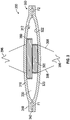
- FIG. 1 shows a cross-sectional view of one embodiment of a pump assembly 100.
- the pump assembly 100 has a first membrane 110 and a second membrane 120 that define a chamber 130 therebetween.
- the first and second membranes 110, 120 are made of a flexible material, such as closed cell foam or open cell foam with an impermeable skin.
- the first and second membranes 110, 120 can be made of other suitable materials, such as Polyurethane, Polyethylene terephthalate (PET), and silicone.
- PET Polyethylene terephthalate
- the first and second membranes 110, 120 can optionally be sealed together along their respective edges to define the chamber 130.
- edges of the first and second membranes 110, 120 can be sealed via welding (e.g., ultrasonic, heat, etc.) or via an adhesive.
- the chamber 130 can have a volume V of between about 20 mm 3 and about 1000 mm 3 .
- the pump assembly 100 has an inlet portion 140 with an inlet passage 142 in fluid communication with the chamber 130.
- the pump assembly 100 has an outlet portion 150 with an outlet passage 152 in fluid communication with the chamber 130.
- the inlet portion 140 optionally includes a one-way valve 160 that allows fluid flow through the inlet passage 142 into the chamber 130 but inhibits (e.g., prevents) flow from the chamber 130 into the inlet passage 142 (e.g., inhibits reverse flow into the inlet passage 142).
- the outlet portion 150 optionally includes a one-way valve 170 that allows fluid flow from the chamber 130 and through the outlet passage 152 but inhibits (e.g., prevents) flow from the outlet passage 152 into the chamber 130 (e.g., inhibits reverse flow into the chamber 130).
- the pump assembly 100 includes first magnetic actuator, such as a magnet 180, proximate an inner surface 112 of the first membrane 110 and includes a second magnetic actuator, such as an electromagnet 190, proximate an inner surface 122 of the second membrane 120.
- the electromagnet 190 can optionally be a voice coil.
- the magnet 180 is attached to the inner surface 112 and the electromagnet 190 is attached to the inner surface 122.
- the electromagnet 190 is cylindrical and has a diameter 192 and the magnet 180 is annular and has an opening 182 with an inner diameter 184 that is greater than the diameter 192 of the electromagnet 190, allowing the electromagnet 190 to at least partially extend into the opening 182 when the membranes 110, 120 move toward each other, as further discussed below.
- the electromagnet 190 can be in the form of a coil having a body formed from a length of wound conductive wire, such as without limitation copper wire or any other electrically conductive material.
- a magnetic field can be generated generally directed along a direction parallel to an axial centerline for the coil.
- an electrical conduit 198 can be connected to both ends of the coil.
- the electrical conduit 198 can be a flexible printed circuit (FPC) attached to a circuit board (not shown).
- FPC flexible printed circuit
- Other types of electrical conduits, such as elongate wires, can be used.
- the coil can be formed by winding approximately 160 turns of wire, or from approximately 100 turns or less to 200 turns or more of wire, which can be but is not required to be, 42 gauge (approximately 0.102 mm diameter) wire.
- the wire used can be self-bonding wire that bonds to adjacent sections of wire upon application of heat.
- the wire can also be non-self-bonding wire.
- approximately 200 turns of wire, or up to approximately 260 turns of wire can be used to form the coil. Increasing the number of turns of wire can potentially reduce ohmic losses and improve the overall efficiency of the pump assembly 100 by between approximately 22% and approximately 24%.
- the size or thickness of the magnet can be decreased, thereby reducing the magnetic field outside of the pump assembly 100 that can potentially interfere with the function of pacemakers and other implanted cardiac devices (ICDs).
- the electromagnet 190 is selectively supplied with an electric current (e.g., alternating current) from a power source 196.
- the electric current can flow through the electromagnet 190 to generate a magnetic field such that a magnetic force can be applied to the electromagnet 190 by virtue of the permanent magnetic field provided by the magnet 180.
- the magnetic force applied to the electromagnet 190 by the magnet 180 is transmitted to the first and second membranes 110, 120, which cause the membranes 110, 120 to move toward and away from each other.
- the membranes 110, 120 can move toward each other when current flows through the electromagnet 190 in one direction, and the membranes 110, 120 can move away from each other when current flows though the electromagnet 190 in a second direction opposite to the first direction to reverse the direction of the magnetic field generated in the electromagnet 190.
- the pump assembly 100 can pump a fluid (e.g., air) through the chamber 130 via reciprocation of the membranes 110, 120 toward and away from each other due to forces generated by the electromagnet 190 relative to the magnet 180.
- a fluid e.g., air
- the pump assembly 100 can pump a fluid (e.g., air) through the chamber 130 via reciprocation of the membranes 110, 120 toward and away from each other due to forces generated by the electromagnet 190 relative to the magnet 180.
- a fluid e.g., air
- the one-way valves 160, 170 ensure that fluid flows through the chamber 130 in one direction (e.g., along direction F1 and F2) to thereby pump the fluid from an upstream location (e.g., a wound location).
- the one-way valves 160, 170 are separate components disposed in the inlet and outlet passages 142, 152, respectively.
- the one-way valves 160, 170 are integrally formed with the membranes 110, 120.
- each of the one-way valves 160, 170 can be formed by a directional piercing through walls of the membranes 110, 120 (e.g., where the membranes 110, 120 join the inlet and outlet portions 140, 150).
- a directional piercing can optionally define a flap that can move in one direction to allow flow through a flow passage (e.g., the inlet or outlet passage 142, 152), and that can move in an opposite direction to substantially seal the flow passage, depending on the direction of fluid flow.
- one or both of the one -way valves 160, 170 can include materials that change shape when exposed to an electrical potential (e.g., a temporary potential, a continuous potential), such as liquid crystals, allowing the complete opening or closure of the valve 160, 170 in addition to one-way flow operation.
- an electrical potential e.g., a temporary potential, a continuous potential
- one or both of the one-way valves 160, 170 can incorporate materials that swell on contact with a liquid. Such materials can advantageously allow the sealing of the flow passage and stopping pumping action by the pump assembly 100, for example, if a wound dressing in fluid communication with the pump assembly 100 becomes full.
- FIG. 2 shows another embodiment of a pump assembly 200.
- the pump assembly 200 is similar to the pump assembly 100 shown in FIG. 1 , except as noted below.
- the reference numerals used to designate the various components of the pump assembly 200 are identical to those used for identifying the corresponding components of the pump assembly 100 in FIG. 1 , except that the reference numerals of the pump assembly 200 begin with a "2". Therefore the description for the various components of the pump assembly 100 shown in FIG. 1 is understood to apply to the corresponding components of the pump assembly 200 in FIG. 2 , except as described below.
- the pump assembly 200 has a magnet 280 proximate an inner surface 212 of a first membrane 210 and an electromagnet 290, such as a voice coil, proximate an inner surface 222 of a second membrane 220.
- the magnet 280 is optionally cylindrical with an outer diameter 284.
- the electromagnet 290 is optionally cylindrical and has an inner diameter 292.
- the inner diameter 292 of the electromagnet 290 is larger than the outer diameter 284 of the magnet 280, allowing the magnet 280 to at least partially extend into a space defined by the inner diameter 292 of the electromagnet 290.
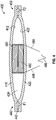
- FIG. 3 shows another embodiment of a pump assembly 300.
- the pump assembly 300 is similar to the pump assembly 100 shown in FIG. 1 , except as noted below.
- the reference numerals used to designate the various components of the pump assembly 300 are identical to those used for identifying the corresponding components of the pump assembly 100 in FIG. 1 , except that the reference numerals of the pump assembly 300 begin with a "3". Therefore the description for the various components of the pump assembly 100 shown in FIG. 1 is understood to apply to the corresponding components of the pump assembly 300 in FIG. 3 , except as described below.
- the pump assembly 300 has a first electromagnet 380 proximate an inner surface 312 of a first membrane 310 and a second electromagnet 390 proximate an inner surface 322 of a second membrane 320.
- the first electromagnet 380 is optionally cylindrical with an inner diameter 384.
- the second electromagnet 390 is optionally cylindrical and has an outer diameter 392.
- the outer diameter 392 of the second electromagnet 390 is smaller than the inner diameter 384 of the first electromagnet 380, allowing the second electromagnet 390 to at least partially extend into a space defined by the inner diameter 384 of the first electromagnet 380.
- the first and second electromagnets 380, 390 are selectively supplied with an electric current (e.g., alternating current) from a power source 396.
- an electric current e.g., alternating current
- the first electromagnet 380 can be supplied with an electric current in anti-phase to that supplied to the second electromagnet 390.
- the electric current can flow through the electromagnets 380, 390 to generate a magnetic field such that a magnetic force can be applied to the electromagnets 380, 390.
- the magnetic force applied to the electromagnets 380, 390 by the generated magnetic fields is transmitted to the first and second membranes 310, 320, which cause the membranes 310, 320 to move toward and away from each other.
- the membranes 310, 320 can move toward each other when current flows through the electromagnets 380, 390 in one direction, and the membranes 310, 320 can move away from each other when current flows though the electromagnets 380, 390 in a second direction opposite to the first direction to reverse the direction of the magnetic field generated in the electromagnets 380,390.
- FIG. 4 shows another embodiment of a pump assembly 400.
- the pump assembly 400 is similar to the pump assembly 300 shown in FIG. 3 , except as noted below.
- the reference numerals used to designate the various components of the pump assembly 400 are identical to those used for identifying the corresponding components of the pump assembly 300 in FIG. 3 , except that the reference numerals of the pump assembly 400 begin with a "4". Therefore the description for the various components of the pump assembly 300 shown in FIG. 3 is understood to apply to the corresponding components of the pump assembly 400 in FIG. 4 , except as described below.
- the pump assembly 400 has a first electromagnet 480 proximate an inner surface 412 of a first membrane 410 and a second electromagnet 490 proximate an inner surface 422 of a second membrane 420.
- the first electromagnet 480 is connected in series with the second electromagnet 490.
- the first electromagnet 480 is wound in the opposite direction as the second electromagnet 490.
- the first and second electromagnets 480, 490 are selectively supplied with an electric current (e.g., alternating current) from a power source 496.
- the electric current can flow through the electromagnets 480, 490 to generate a magnetic field such that a magnetic force can be applied to the electromagnets 480, 490.
- the magnetic force applied to the electromagnets 480, 490 by the generated magnetic fields is transmitted to the first and second membranes 410, 420, which cause the membranes 410, 420 to move toward and away from each other.
- the membranes 410, 420 can move toward each other when current flows through the electromagnets 480, 490 in one direction, and the membranes 410, 420 can move away from each other when current flows though the electromagnets 480, 490 in a second direction opposite to the first direction to reverse the direction of the magnetic field generated in the electromagnets 480,490.
- first and second electromagnets 480, 490 can instead be connected in parallel, where the first electromagnet 480 is wound in the opposite direction than the second electromagnet 490.
- FIG. 5 shows another embodiment of a pump assembly 500.
- the pump assembly 500 is similar to the pump assembly 100 shown in FIG. 1 , except as noted below.
- the reference numerals used to designate the various components of the pump assembly 500 are identical to those used for identifying the corresponding components of the pump assembly 100 in FIG. 1 , except that the reference numerals of the pump assembly 500 begin with a "5". Therefore the description for the various components of the pump assembly 100 shown in FIG. 1 is understood to apply to the corresponding components of the pump assembly 500 in FIG. 5 , except as described below.
- the pump assembly 500 has a magnet 580 proximate an inner surface 512 of a first membrane 510 and an electromagnet 590 proximate an inner surface 522 of a second membrane 520.
- the magnet 580 is shaped like a plate with a substantially planar (e.g., a planar or flat) surface 582 that faces the electromagnet 590.
- FIG. 6 shows another embodiment of a pump assembly 600.
- the pump assembly 500 is similar to the pump assembly 100 shown in FIG. 1 , except as noted below.
- the reference numerals used to designate the various components of the pump assembly 600 are identical to those used for identifying the corresponding components of the pump assembly 100 in FIG. 1 , except that the reference numerals of the pump assembly 600 begin with a "6". Therefore the description for the various components of the pump assembly 100 shown in FIG. 1 is understood to apply to the corresponding components of the pump assembly 600 in FIG. 6 , except as described below.
- the pump assembly 600 has a first magnet 680 proximate an inner surface 612 of a first membrane 610 and a first electromagnet 690 proximate an inner surface 622 of a second membrane 620.
- the pump assembly 600 also has a second magnet 685 proximate an inner surface 612 of the first membrane 610 and a second electromagnet 695 proximate an inner surface 622 of the second membrane 620.
- the first and second magnets 680, 685 are cylindrical with the inner diameter 684 of the first magnet 680 being greater than the outer diameter 687 of the second magnet 685, such that the first magnet 680 is disposed about the second magnet 685.
- the first and second electromagnets 690, 695 are cylindrical with the inner diameter 692 of the first electromagnet 690 being greater than the outer diameter 697 of the second electromagnet 695, such that the first electromagnet 690 is disposed about the second electromagnet 695.
- the inner diameter 692 of the first electromagnet 690 is greater than an outer diameter of the first magnet 680
- an inner diameter of the second electromagnet 695 is greater than the outer diameter 687 of the second magnet 685, such that the first and second magnets 680, 685 extend at least partially within spaces in the first and second electromagnets 690, 695 during operation of the pump assembly 600.
- the first magnet 680 can have an inner diameter larger than an outer diameter of the first electromagnet 690 and the second magnet 685 can have an inner diameter larger than an outer diameter of the second electromagnet 695.
- first and second electromagnets 690, 695 are selectively supplied with an electric current (e.g., alternating current) from a power source 696.
- the electric current can flow through the electromagnets 690, 695 to generate a magnetic field such that a magnetic force can be applied to the electromagnets 690, 695 by virtue of the permanent magnetic field provided by the first and second magnets 680, 685.
- the magnetic force is transmitted to the first and second membranes 610, 620, which cause the membranes 610, 620 to move toward and away from each other.
- the membranes 610, 620 can move toward each other when current flows through the electromagnets 690, 695 in one direction, and the membranes 610, 620 can move away from each other when current flows though the electromagnets 690, 695 in a second direction opposite to the first direction to reverse the direction of the magnetic field generated in the electromagnets 690, 695.
- one or more of the magnets disclosed herein can be printed, electro-statically deposited or otherwise applied onto the surface of the membrane (e.g., membranes 110, 210).
- one or more of the magnets disclosed herein can be attached onto a corresponding surface of the membrane (e.g., as an adhesive patch).
- one or more of the electromagnets disclosed herein can be printed, electrostatically deposited or otherwise applied onto the surface of the membrane (e.g., membranes 110, 120, 210, 220, 310, 320, 410, 420).
- one or more of the electromagnets disclosed herein can be attached onto a corresponding surface of the membrane (e.g., as an adhesive patch).
- one or both of the membranes (such as the membranes 110, 120, 210, 220, etc.) in each pump assembly can include a bi-stable element therein to aid the membrane in reaching a retracted or extended position by allowing the membrane to snap into the retracted and/or extended position.
- the pump assembly (such as the pump assemblies discussed above) can have a chamber (such as chamber 130) that is mono-stable, so that the chamber is biased toward one direction (e.g., toward moving the membranes to the expended position), and where an electropotential is applied to the electromagnet in only one direction (e.g., to move the membranes to the retracted position).
- a chamber such as chamber 130
- an electropotential is applied to the electromagnet in only one direction (e.g., to move the membranes to the retracted position).
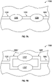
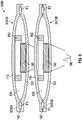
- FIGS. 7A-7B shows an array 1000 of pump assemblies (such as any of the pump assemblies disclosed above). Though FIGS. 7A-7B show an array 1000 with two pump assemblies, one of skill in the art will recognize that the array 1000 can have more than two pump assemblies.
- FIG. 7A shows a first pump assembly 1010 and a second pump assembly 1020 arranged in series between an inlet portion 1030 and an outlet portion 1040, the pump assemblies 1010, 1020 interconnected by an intermediate portion 1050.
- Arranging the pump assemblies 1010, 1020 in series advantageously allows for the array 1000 to have an increased pressure capability.
- the first and second pump assemblies 1010, 1020 can operate in anti-phase to each other to reinforce fluid movement between the assemblies.
- FIG. 7B shows a first pump assembly 1010' and a second pump assembly 1020' arranged in parallel between an inlet portion 1030 and an outlet portion 1040.
- the inlet portion 1030 is in fluid communication with the pump assemblies 1010', 1020' via an inlet manifold 1050'
- the outlet portion 1040 is in fluid communication with the pump assemblies 1010', 1020' via an outlet manifold 1060'.
- Arranging the pump assemblies 1010', 1020' in parallel advantageously allows the array 1000 to generate an increased flow rate therethrough.
- the first and second pump assemblies 1010', 1020' can operate in phase relative to each other to effect fluid movement through the array 1000.
- FIG. 8 shows another embodiment of an array 2000 that includes two or more pump assemblies (such as any of the pump assemblies disclosed above).
- the array 2000 has a first pump assembly 2010 and a second pump assembly 2020 disposed between an inlet portion 2030 and an outlet portion 2040 of the array 2000.
- a chamber 2050 is interposed between the pump assemblies 2010, 2020 and interconnected via passages 2060A, 2060B with the pump assemblies 2010, 2020.
- the chamber 2050 does not have magnets or electromagnets therein, and can serve as a pressure or vacuum accumulator and/or to smooth flow through the array 2000.
- FIG. 8 shows an array 2000 with two pump assemblies and one accumulator chamber, one of skill in the art will recognize that the array 2000 can have more than two pump assemblies and a plurality of accumulator chambers.
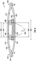
- FIG. 9 shows another embodiment of a pump system 3000 that includes two or more pump assemblies (such as any of the pump assemblies disclosed above).
- the pump system 3000 has a first pump assembly 3010A and a second pump assembly 3010B arranged one over the other in separate layers.
- the first and second pump assemblies 310A, 310B extend between inlet portions 3030A, 3030B and outlet portions 3040A, 3040B, respectively.
- the first and second pump assemblies 3010A, 3010B are operated in anti-phase so that the common wall or membrane between the assemblies 3010A, 3010B is driven by the electromagnetic elements in both assemblies 3010A, 3010B.
- FIG. 10 shows a pump system 4000 in fluid communication with a wound dressing 950 via a conduit 954 that connects to a port 952 on the dressing 950.
- the pump system 4000 can include one or more pump assemblies (such as the pump assemblies disclosed above).
- the pump system 4000 includes an array (such as one of the arrays disclosed above).
- the pump system 4000 can be configured to operate in a canisterless system, in which the wound dressing, such as wound dressing 950, retains exudate aspirated from the wound.
- a dressing can include a filter, such as a hydrophobic filter, that prevents passage of liquids downstream of the dressing (toward the pump system).
- the pump system can be configured to operate in a system having a canister for storing at least part of exudate aspirated from the wound.
- a canister for storing at least part of exudate aspirated from the wound.
- Such canister can include a filter, such as a hydrophobic filter, that prevents passage of liquids downstream of the dressing (toward the pump system).
- both the dressing and the canister can include filters that prevent passage of liquids downstream of the dressing and the canister.
- the dressing 950 can include one or more layer of woven, non-woven foam or superabsorbent layer, or a combination thereof.
- FIG. 11A shows one embodiment of a dressing 950A with a pump system 5000 in fluid communication with the dressing 950A via a conduit 954A.
- the pump system 5000 can be coupled to the dressing 950A, for example via an adhesive) so that the pump system 5000 is disposed on the dressing 950A.
- the pump system 5000 can include one or more pump assemblies P (such as the pump assemblies disclosed above).
- the pump system 5000 includes an array (such as one of the arrays disclosed above).
- the dressing 950A can include one or more layer of woven, non-woven foam or superabsorbent layer, or a combination thereof
- FIG. 11B shows another embodiment of a dressing assembly 950B with a pump system 6000 incorporated into the dressing assembly 950B.
- An internal conduit 954B can fluidly interconnect the pump system 6000 with the wound site (e.g., via one or more layers of the dressing 950B).
- the pump system 6000 can include one or more pump assemblies P (such as the pump assemblies disclosed above).
- the pump system 6000 includes an array (such as one of the arrays disclosed above).
- the dressing 950B can include one or more layer of woven, non-woven foam or superabsorbent layer, or a combination thereof.
- the magnets disclosed herein can be made of any suitable material, such as mild steel, a sintered soft magnetic metal such as GKN 72-IBP2 (S-FeP-130), or sintered steel (or any suitable magnetic or ferromagnetic material).
- the magnet can be made from Neodymium-Iron-Boron (NdFeB) - N 45 M, Neodymium N33, or any other suitable material magnetic material. This material can be used to maximize field strength and minimize losses, thereby increasing the efficiency of the pump unit (e.g., pump assembly 100).
- the pump assembly designs disclosed herein provide various advantages. For example, such pump assemblies are flexible and therefore do not generate pressure points if lain upon (for example if the pump assembly is attached to, or incorporated in, a wound dressing assembly). Additionally, the pump assemblies disclosed herein are smaller and simpler to assemble than existing drum pumps. Further, when provided as part of a wound dressing (e.g., whether attached to or integrally formed with the wound dressing), the pump assemblies can be scalable with the dressing size, allowing the size of the array to be adjusted along with the size of the wound dressing, and thereby have a lower unit cost than existing pump assemblies. Still another advantage of the pump assemblies disclosed herein is that their structure can allow for smaller gaps between the magnetic actuators (e.g., smaller gap between the magnet 180 and electromagnet 190 in FIG. 1 ), thereby increasing the efficiency of the pump assembly.
- the magnetic actuators e.g., smaller gap between the magnet 180 and electromagnet 190 in FIG. 1
- Embodiments of the pump systems are not limited to use with a dressing or for wound therapy. Any of the embodiments of the pump systems disclosed herein can be used independently of a wound dressing. Further, any of the embodiments of the pump systems disclosed herein can be used, or can be adapted for use, for other purposes outside of negative pressure wound therapy. As such, any of the embodiments of pump systems disclosed herein can be used, or can be adapted for use, to move fluids (gaseous and/or liquid) in any system or application.
- any value of a threshold, limit, duration, etc. provided herein is not intended to be absolute and, thereby, can be approximate.
- any threshold, limit, duration, etc. provided herein can be fixed or varied either automatically or by a user.
- Various components illustrated in the figures may be implemented as software and/or firmware on a processor, controller, ASIC, FPGA, and/or dedicated hardware.
- Hardware components such as processors, ASICs, FPGAs, and the like, can include logic circuitry.
- the features and attributes of the specific embodiments disclosed above may be combined in different ways to form additional embodiments, all of which fall within the scope of the present disclosure.
- the separation of various system components in the implementations described above should not be understood as requiring such separation in all implementations, and it should be understood that the described components and systems can generally be integrated together in a single product or packaged into multiple products.
- the terms “generally parallel” and “substantially parallel” refer to a value, amount, or characteristic that departs from exactly parallel by less than or equal to 15 degrees, 10 degrees, 5 degrees, 3 degrees, 1 degree, or 0.1 degree.
Landscapes
- Health & Medical Sciences (AREA)
- Heart & Thoracic Surgery (AREA)
- General Health & Medical Sciences (AREA)
- Engineering & Computer Science (AREA)
- Biomedical Technology (AREA)
- Life Sciences & Earth Sciences (AREA)
- Animal Behavior & Ethology (AREA)
- Vascular Medicine (AREA)
- Public Health (AREA)
- Veterinary Medicine (AREA)
- Anesthesiology (AREA)
- Hematology (AREA)
- External Artificial Organs (AREA)
- Reciprocating Pumps (AREA)
Applications Claiming Priority (3)
| Application Number | Priority Date | Filing Date | Title |
|---|---|---|---|
| US201562163170P | 2015-05-18 | 2015-05-18 | |
| US201662332411P | 2016-05-05 | 2016-05-05 | |
| PCT/EP2016/061139 WO2016184913A1 (en) | 2015-05-18 | 2016-05-18 | Negative pressure wound therapy apparatus and methods |
Publications (2)
| Publication Number | Publication Date |
|---|---|
| EP3297697A1 EP3297697A1 (en) | 2018-03-28 |
| EP3297697B1 true EP3297697B1 (en) | 2022-05-11 |
Family
ID=57319499
Family Applications (1)
| Application Number | Title | Priority Date | Filing Date |
|---|---|---|---|
| EP16723138.0A Active EP3297697B1 (en) | 2015-05-18 | 2016-05-18 | Negative pressure wound therapy apparatus |
Country Status (5)
| Country | Link |
|---|---|
| US (1) | US10973693B2 (enExample) |
| EP (1) | EP3297697B1 (enExample) |
| JP (1) | JP6812363B2 (enExample) |
| CN (1) | CN107580509B (enExample) |
| WO (1) | WO2016184913A1 (enExample) |
Cited By (1)
| Publication number | Priority date | Publication date | Assignee | Title |
|---|---|---|---|---|
| US11883577B2 (en) | 2016-07-08 | 2024-01-30 | Convatec Technologies Inc. | Fluid collection apparatus |
Families Citing this family (25)
| Publication number | Priority date | Publication date | Assignee | Title |
|---|---|---|---|---|
| US9421132B2 (en) | 2011-02-04 | 2016-08-23 | University Of Massachusetts | Negative pressure wound closure device |
| CN104736110B (zh) | 2012-05-24 | 2019-05-31 | 史密夫和内修有限公司 | 用于利用负压来处理和封闭伤口的装置和方法 |
| RU2015104581A (ru) | 2012-07-16 | 2016-09-10 | Смит Энд Нефью, Инк. | Устройство для закрытия раны с использованием отрицательного давления |
| WO2014165275A1 (en) | 2013-03-13 | 2014-10-09 | Smith & Nephew Inc. | Negative pressure wound closure device and systems and methods of use in treating wounds with negative pressure |
| EP4209201A1 (en) | 2015-04-29 | 2023-07-12 | Smith & Nephew, Inc. | Negative pressure wound closure device |
| JP2018529407A (ja) | 2015-08-13 | 2018-10-11 | スミス アンド ネフュー インコーポレイテッド | 陰圧治療をかけるためのシステム及び方法 |
| US10575991B2 (en) | 2015-12-15 | 2020-03-03 | University Of Massachusetts | Negative pressure wound closure devices and methods |
| WO2018237206A2 (en) * | 2017-06-21 | 2018-12-27 | University Of Massachusetts | Negative pressure wound closure devices and methods |
| US10814049B2 (en) | 2015-12-15 | 2020-10-27 | University Of Massachusetts | Negative pressure wound closure devices and methods |
| JP6926239B2 (ja) | 2017-02-15 | 2021-08-25 | スミス・アンド・ネフュー・アジア・パシフィク・ピーティーイー・リミテッド | 陰圧創傷治療装置およびその使用方法 |
| EP3585453B1 (en) | 2017-02-22 | 2023-05-17 | Cornell University | Mechanical vacuum dressing for mechanically managing, protecting and suctioning small incisional wounds |
| US11389582B2 (en) | 2017-09-29 | 2022-07-19 | T.J. Smith And Nephew, Limited | Negative pressure wound therapy apparatus with removable panels |
| CN111432855B (zh) | 2017-12-06 | 2024-02-23 | 康奈尔大学 | 具有提高的泵效率、自动压力指示器和自动压力限制器的手动操作的负压伤口治疗(npwt)绷带 |
| GB201813282D0 (en) | 2018-08-15 | 2018-09-26 | Smith & Nephew | System for medical device activation and opertion |
| WO2019157466A1 (en) | 2018-02-12 | 2019-08-15 | Healyx Labs, Inc. | Negative pressure wound therapy systems, devices, and methods |
| GB201804347D0 (en) | 2018-03-19 | 2018-05-02 | Smith & Nephew Inc | Securing control of settings of negative pressure wound therapy apparatuses and methods for using the same |
| WO2019211731A1 (en) | 2018-04-30 | 2019-11-07 | Smith & Nephew Pte. Limited | Systems and methods for controlling dual mode negative pressure wound therapy apparatus |
| GB201806988D0 (en) | 2018-04-30 | 2018-06-13 | Quintanar Felix Clarence | Power source charging for negative pressure wound therapy apparatus |
| GB201808438D0 (en) | 2018-05-23 | 2018-07-11 | Smith & Nephew | Systems and methods for determining blockages in a negative pressure wound therapy system |
| WO2020124038A1 (en) | 2018-12-13 | 2020-06-18 | University Of Massachusetts | Negative pressure wound closure devices and methods |
| GB201914283D0 (en) | 2019-10-03 | 2019-11-20 | Smith & Nephew | Apparatuses and methods for negative pressure wound therapy |
| GB201914427D0 (en) * | 2019-10-07 | 2019-11-20 | Smith & Nephew | Negative pressure wound therapy systems and methods with multiple negative pressure sources |
| EP4097357B1 (en) * | 2020-01-29 | 2023-10-18 | ConvaTec Limited | A pump assembly and a wound therapy apparatus |
| EP4294474B1 (en) * | 2021-02-18 | 2026-03-11 | KCI Manufacturing Unlimited Company | Systems for detecting fluid contamination in a wound therapy system |
| AU2024225341A1 (en) | 2023-02-21 | 2025-09-04 | Osteal Therapeutics, Inc. | Methods of treating a localized infection with locally administered antibiotics |
Citations (1)
| Publication number | Priority date | Publication date | Assignee | Title |
|---|---|---|---|---|
| US20090125004A1 (en) * | 2007-11-09 | 2009-05-14 | Industrial Technology Research Institute | Detachable pump and the negative pressure wound therapy system using the same |
Family Cites Families (137)
| Publication number | Priority date | Publication date | Assignee | Title |
|---|---|---|---|---|
| FR1535489A (fr) | 1967-04-21 | 1968-08-09 | Perfectionnements aux moteurs à courant continu sans collecteur et à certains dispositifs qui les utilisent | |
| JPS5647279U (enExample) * | 1979-09-20 | 1981-04-27 | ||
| JPS5647279A (en) | 1979-09-27 | 1981-04-28 | Daihen Corp | Co2 gas shielded arc welding |
| IL59942A (en) | 1980-04-28 | 1986-08-31 | D P Lab Ltd | Method and device for fluid transfer |
| US5527274A (en) | 1986-06-09 | 1996-06-18 | Development Collaborative Corporation | Catheter for chemical contact dissolution of gallstones |
| US4731076A (en) * | 1986-12-22 | 1988-03-15 | Baylor College Of Medicine | Piezoelectric fluid pumping system for use in the human body |
| JPH01101978A (ja) * | 1987-10-15 | 1989-04-19 | Japan Medical Dynamic Marketing Inc | 流量切替式脳室シャント |
| SE508435C2 (sv) * | 1993-02-23 | 1998-10-05 | Erik Stemme | Förträngningspump av membranpumptyp |
| USD357735S (en) | 1993-08-03 | 1995-04-25 | I-Flow Corporation | Valve for filling an IV solution bag |
| JPH0796029A (ja) | 1993-09-30 | 1995-04-11 | Nippon Zeon Co Ltd | 胆汁還流カテーテル |
| ATE172377T1 (de) | 1994-08-22 | 1998-11-15 | Kinetic Concepts Inc | Wunddrainagevorrichtung |
| US5712795A (en) | 1995-10-02 | 1998-01-27 | Alaris Medical Systems, Inc. | Power management system |
| EP1738782A1 (en) | 1995-10-20 | 2007-01-03 | Haemonetics Corporation | Filter bag |
| WO1997026928A1 (en) | 1996-01-24 | 1997-07-31 | Radford Fred R | Contaminated medical waste disposal system and method |
| US7214202B1 (en) | 1997-07-28 | 2007-05-08 | Kci Licensing, Inc. | Therapeutic apparatus for treating ulcers |
| US6682500B2 (en) | 1998-01-29 | 2004-01-27 | David Soltanpour | Synthetic muscle based diaphragm pump apparatuses |
| KR20000050679A (ko) * | 1999-01-13 | 2000-08-05 | 윤종용 | 전자기기용 방열장치 |
| WO2000061206A1 (en) | 1999-04-09 | 2000-10-19 | Kci Licensing, Inc. | Wound therapy device |
| JP3666307B2 (ja) | 1999-06-30 | 2005-06-29 | 松下電器産業株式会社 | 二次電池の残量表示方法と二次電池の残量表示方法を備えた携帯型電子機器 |
| US7064472B2 (en) * | 1999-07-20 | 2006-06-20 | Sri International | Electroactive polymer devices for moving fluid |
| US6824533B2 (en) | 2000-11-29 | 2004-11-30 | Hill-Rom Services, Inc. | Wound treatment apparatus |
| US20020098097A1 (en) * | 2001-01-22 | 2002-07-25 | Angad Singh | Magnetically-actuated micropump |
| US7070584B2 (en) | 2001-02-20 | 2006-07-04 | Kci Licensing, Inc. | Biocompatible wound dressing |
| EP2204213B2 (en) | 2001-07-12 | 2020-04-01 | KCI Licensing, Inc. | Control of vacuum level rate of change |
| US7004915B2 (en) | 2001-08-24 | 2006-02-28 | Kci Licensing, Inc. | Negative pressure assisted tissue treatment system |
| USD475132S1 (en) | 2002-06-26 | 2003-05-27 | Kci Licensing, Inc. | Wound drainage canister |
| US20040068224A1 (en) | 2002-10-02 | 2004-04-08 | Couvillon Lucien Alfred | Electroactive polymer actuated medication infusion pumps |
| US20090216205A1 (en) * | 2003-08-08 | 2009-08-27 | Biodrain Medical, Inc. | Fluid waste collection and disposal system and method |
| US20050065471A1 (en) * | 2003-09-23 | 2005-03-24 | Charles Kuntz | Continuous safe suction device |
| US8038639B2 (en) | 2004-11-04 | 2011-10-18 | Baxter International Inc. | Medical fluid system with flexible sheeting disposable unit |
| US8062272B2 (en) | 2004-05-21 | 2011-11-22 | Bluesky Medical Group Incorporated | Flexible reduced pressure treatment appliance |
| EP1722412B1 (en) * | 2005-05-02 | 2012-08-29 | Sony Corporation | Jet generator and electronic device |
| US7857806B2 (en) | 2005-07-14 | 2010-12-28 | Boehringer Technologies, L.P. | Pump system for negative pressure wound therapy |
| US7608066B2 (en) | 2005-08-08 | 2009-10-27 | Innovative Therapies, Inc. | Wound irrigation device pressure monitoring and control system |
| JP2007218241A (ja) | 2006-01-20 | 2007-08-30 | Sony Corp | 振動アクチュエータ、噴流発生装置及び電子機器 |
| CA2650402C (en) | 2006-05-09 | 2010-10-19 | Medela Holding Ag | Aspiration pump unit |
| MX2009003284A (es) | 2006-09-26 | 2010-02-09 | Boehringer Technologies Lp | Sistema de bomba de presion negativa para terapia de heridas. |
| US8308714B2 (en) | 2006-10-13 | 2012-11-13 | Bluesky Medical Group Inc. | Control circuit and method for negative pressure wound treatment apparatus |
| US7927319B2 (en) | 2007-02-20 | 2011-04-19 | Kci Licensing, Inc. | System and method for distinguishing leaks from a disengaged canister condition in a reduced pressure treatment system |
| CA2687406A1 (en) | 2007-05-07 | 2008-11-13 | Carmeli Adahan | Suction system |
| USD581042S1 (en) | 2007-05-11 | 2008-11-18 | Kci Licensing, Inc. | Reduced pressure treatment system |
| USD590934S1 (en) | 2007-05-11 | 2009-04-21 | Kci Licensing, Inc. | Reduced pressure treatment system |
| JP5290630B2 (ja) | 2007-06-05 | 2013-09-18 | ニプロ株式会社 | 医療用コネクタおよびその製造方法 |
| USD602582S1 (en) | 2007-07-02 | 2009-10-20 | Smith & Nephew LLC | Therapy unit assembly |
| USD602583S1 (en) | 2007-07-02 | 2009-10-20 | Smith & Nephew Plc | Device for applying negative pressure to a wound |
| GB0712758D0 (en) | 2007-07-02 | 2007-08-08 | Smith & Nephew | Battery recharging |
| GB0712739D0 (en) | 2007-07-02 | 2007-08-08 | Smith & Nephew | Apparatus |
| USD602584S1 (en) | 2007-07-02 | 2009-10-20 | Smith & Nephew Plc | Canister |
| USD654164S1 (en) | 2007-07-12 | 2012-02-14 | Talley Group Limited | Wound drainage apparatus for medical purposes |
| US20110060300A1 (en) | 2007-08-17 | 2011-03-10 | Conva Tec Technologies Inc. | Aspiration system for removing liquid discharged by the body, and liquid sensor therefor |
| GB0723855D0 (en) | 2007-12-06 | 2008-01-16 | Smith & Nephew | Apparatus and method for wound volume measurement |
| CA2711620A1 (en) | 2008-01-08 | 2009-07-16 | Bluesky Medical Group Inc. | Sustained variable negative pressure wound treatment and method of controlling same |
| CA2726814C (en) | 2008-05-27 | 2014-05-20 | Kalypto Medical, Inc. | Control unit with pump module for a negative pressure wound therapy device |
| US9138531B2 (en) | 2008-05-29 | 2015-09-22 | Roche Diagnostics Operations, Inc. | Device, a system and a method for identification/authentication of parts of a medical device |
| CN103527452A (zh) * | 2008-06-03 | 2014-01-22 | 株式会社村田制作所 | 压电微型鼓风机 |
| US8480641B2 (en) | 2008-06-13 | 2013-07-09 | Premco Medical Systems, Inc. | Negative pressure wound treatment apparatus and method |
| USD660409S1 (en) | 2008-10-24 | 2012-05-22 | Talley Group Limited | Compact negative pressure wound treatment apparatus |
| AU2009310390B2 (en) | 2008-10-29 | 2015-01-22 | Kci Licensing, Inc. | Medical canister connectors |
| US8226601B2 (en) | 2008-11-12 | 2012-07-24 | Sanovas, Inc. | Resector balloon system |
| FR2939320B1 (fr) | 2008-12-05 | 2010-12-31 | Ind Tech Res Inst | Pompe detachable et systeme de traitement de plaie par pression negative utilisant ce dispositif. |
| US8882678B2 (en) | 2009-03-13 | 2014-11-11 | Atrium Medical Corporation | Pleural drainage system and method of use |
| US8344847B2 (en) | 2009-07-09 | 2013-01-01 | Medtronic Minimed, Inc. | Coordination of control commands in a medical device system having at least one therapy delivery device and at least one wireless controller device |
| DE102009038130A1 (de) | 2009-08-12 | 2011-02-17 | ATMOS Medizin Technik GmbH & Co. KG | Am Körper eines Benutzers tragbare Vorrichtung zur Bereitstellung von Unterdruck für medizinische Anwendungen |
| CH702195A1 (de) | 2009-11-05 | 2011-05-13 | Medela Holding Ag | Drainagepumpeinheit |
| USD645137S1 (en) | 2009-12-04 | 2011-09-13 | Smith & Nephew Plc | Canister |
| WO2011075706A1 (en) | 2009-12-18 | 2011-06-23 | K&Y Corporation | Infusion pump |
| US8066243B2 (en) | 2010-01-08 | 2011-11-29 | Richard C. Vogel | Adapter for portable negative pressure wound therapy device |
| CA2784209C (en) | 2010-01-29 | 2018-10-30 | Kci Licensing, Inc. | Wound treatment apparatuses and methods for controlled delivery of fluids to a wound |
| DE102010007464B4 (de) * | 2010-02-10 | 2016-09-29 | Fresenius Medical Care Deutschland Gmbh | Medizinische Funktionseinrichtung, Behandlungsvorrichtung sowie Verfahren |
| CH702650A1 (de) | 2010-02-11 | 2011-08-15 | Medela Holding Ag | Vorrichtung und Verfahren zur Erkennung von Kopplungen zwischen zwei Systemkomponenten. |
| US20110288535A1 (en) | 2010-05-18 | 2011-11-24 | Christopher Brian Locke | Systems and methods for measuring reduced pressure employing an isolated fluid path |
| US8409160B2 (en) * | 2010-05-18 | 2013-04-02 | Kci Licensing, Inc. | Reduced-pressure treatment systems and methods employing a fluidly isolated pump control unit |
| WO2012004298A1 (en) | 2010-07-06 | 2012-01-12 | Novo Nordisk A/S | System for indicating lifetime status for medical component |
| GB201015656D0 (en) | 2010-09-20 | 2010-10-27 | Smith & Nephew | Pressure control apparatus |
| CH704072A1 (de) | 2010-11-15 | 2012-05-15 | Medela Holding Ag | Tragbare Absaugpumpeinheit |
| CH704423A1 (de) | 2011-01-17 | 2012-07-31 | Medela Holding Ag | Drainagepumpeinheit. |
| CN102068750B (zh) | 2011-01-26 | 2013-05-15 | 惠州市华阳医疗电子有限公司 | 基于系统设备管理的负压伤口治疗系统 |
| USD788293S1 (en) | 2011-03-03 | 2017-05-30 | Paul Hartmann Ag | Vacuum generating device |
| JP5502017B2 (ja) * | 2011-04-15 | 2014-05-28 | 株式会社テクノ高槻 | 電磁振動型ダイヤフラムポンプ |
| DE102011075842A1 (de) | 2011-05-13 | 2012-11-15 | Paul Hartmann Ag | Vorrichtung zur Bereitstellung von Unterdruck zur medizinischen Unterdruckbehandlung von Wunden |
| RU2596728C2 (ru) | 2011-07-26 | 2016-09-10 | Смит Энд Нефью Плс | Системы и методы контроля за работой системы для терапии пониженного давления |
| WO2013039623A1 (en) | 2011-09-13 | 2013-03-21 | Kci Licensing, Inc. | Reduced-pressure canisters having hydrophobic pores |
| USD707355S1 (en) | 2011-09-29 | 2014-06-17 | Medline Industries, Inc. | Connector |
| US9084845B2 (en) | 2011-11-02 | 2015-07-21 | Smith & Nephew Plc | Reduced pressure therapy apparatuses and methods of using same |
| CN103930138B (zh) | 2011-11-23 | 2016-06-22 | 凯希特许有限公司 | 用于同时处理多个组织部位的减压系统、方法和装置 |
| US9901664B2 (en) | 2012-03-20 | 2018-02-27 | Smith & Nephew Plc | Controlling operation of a reduced pressure therapy system based on dynamic duty cycle threshold determination |
| US20180021178A1 (en) | 2012-03-28 | 2018-01-25 | Kci Licensing, Inc. | Reduced-Pressure Systems, Dressings, Pump Assemblies And Methods |
| CN103357076A (zh) | 2012-04-05 | 2013-10-23 | 戴闻医疗产品奥克维尔分销公司 | 负压伤口治疗泵的节能控制系统 |
| US8858517B2 (en) | 2012-04-05 | 2014-10-14 | Oakwell Distribution, Inc. | Power saving control system for negative pressure wound therapy pumps |
| US9095644B2 (en) | 2012-04-13 | 2015-08-04 | Apex Medical Corp. | Fluid collector |
| US9427505B2 (en) | 2012-05-15 | 2016-08-30 | Smith & Nephew Plc | Negative pressure wound therapy apparatus |
| GB201216928D0 (en) | 2012-09-21 | 2012-11-07 | I2R Medical Ltd | Portable medical device system |
| EP2711033A1 (de) | 2012-09-25 | 2014-03-26 | Paul Hartmann AG | System für die Wundtherapie |
| US9199010B2 (en) | 2012-11-26 | 2015-12-01 | Apex Medical Corp. | Wound drainage therapy system |
| JP2016054748A (ja) | 2013-01-24 | 2016-04-21 | Lwj株式会社 | 人工心臓ユニット、人工心臓および磁石ユニット |
| EP2968700B1 (en) | 2013-03-13 | 2019-07-24 | KCI Licensing, Inc. | Collapsible canister for use with reduced pressure therapy device |
| WO2014164655A1 (en) | 2013-03-13 | 2014-10-09 | Thermedx, Llc | Fluid management system |
| USD764654S1 (en) | 2014-03-13 | 2016-08-23 | Smith & Nephew, Inc. | Canister for collecting wound exudate |
| US9737649B2 (en) | 2013-03-14 | 2017-08-22 | Smith & Nephew, Inc. | Systems and methods for applying reduced pressure therapy |
| US9415199B2 (en) | 2013-06-14 | 2016-08-16 | Skill Partner Limited | Leak proof needleless medical connector |
| WO2015003141A1 (en) | 2013-07-03 | 2015-01-08 | Deka Products Limited Partnership | Fluid connector assembly |
| JP6679483B2 (ja) | 2013-08-13 | 2020-04-15 | スミス アンド ネフュー インコーポレイテッド | 減圧治療を実施するためのシステムおよび方法 |
| USD730518S1 (en) | 2013-09-12 | 2015-05-26 | Nordson Corporation | Quick connect fluid connector |
| USD746446S1 (en) | 2013-11-25 | 2015-12-29 | Medline Industries, Inc. | Connector |
| DE102013226713A1 (de) | 2013-12-19 | 2015-06-25 | Paul Hartmann Ag | System zur kombinierten Unterdruck- und Instillationsbehandlung von Wunden |
| EP3488880B1 (en) | 2014-01-30 | 2020-07-01 | Murata Manufacturing Co., Ltd. | Suction device |
| CA2939632A1 (en) | 2014-02-20 | 2015-08-27 | Kci Licensing, Inc. | Method and system to evacuate one or more dressings using two or more vacuum pumps |
| USD750235S1 (en) | 2014-03-19 | 2016-02-23 | ERBE-USA, Inc. | Endoscope connector |
| USD750236S1 (en) | 2014-03-19 | 2016-02-23 | ERBE-USA, Inc. | Endoscope connector |
| AU359280S (en) | 2014-04-30 | 2014-12-08 | Talley Group Ltd | Negative pressure wound therapy pump |
| USD764653S1 (en) | 2014-05-28 | 2016-08-23 | Smith & Nephew, Inc. | Canister for collecting wound exudate |
| USD764048S1 (en) | 2014-05-28 | 2016-08-16 | Smith & Nephew, Inc. | Device for applying negative pressure to a wound |
| USD764047S1 (en) | 2014-05-28 | 2016-08-16 | Smith & Nephew, Inc. | Therapy unit assembly |
| USD765830S1 (en) | 2014-06-02 | 2016-09-06 | Smith & Nephew, Inc. | Therapy unit assembly |
| EP2959926A1 (de) | 2014-06-26 | 2015-12-30 | Medela Holding AG | Medizinische Saugpumpe und Fluidsammelbehälter |
| EP3169380B1 (en) | 2014-07-18 | 2021-03-10 | 3M Innovative Properties Company | Disposable cartridge for vacuum actuated fluid delivery |
| US10744239B2 (en) | 2014-07-31 | 2020-08-18 | Smith & Nephew, Inc. | Leak detection in negative pressure wound therapy system |
| USD784529S1 (en) | 2014-07-31 | 2017-04-18 | Nordson Corporation | Enteral feeding connector assembly |
| KR102267626B1 (ko) | 2014-11-20 | 2021-06-22 | 삼성전자주식회사 | 전자 장치 및 전자 장치에서의 배터리 관리 방법 |
| AU2015370583B2 (en) | 2014-12-22 | 2020-08-20 | Smith & Nephew Plc | Negative pressure wound therapy apparatus and methods |
| CN107106742B (zh) | 2014-12-30 | 2020-12-15 | 史密夫和内修有限公司 | 用于应用减压治疗的系统和方法 |
| CN107106743B (zh) | 2014-12-30 | 2020-06-05 | 史密夫和内修有限公司 | 用于应用减压治疗的系统和方法 |
| WO2016122976A1 (en) | 2015-01-26 | 2016-08-04 | Becton, Dickinson And Company | Smart portable infusion pump |
| US11179506B2 (en) | 2015-02-27 | 2021-11-23 | Cork Medical, Llc | Negative pressure wound therapy pump and canister |
| USD750222S1 (en) | 2015-04-27 | 2016-02-23 | Koge Micro Tech Co., Ltd | Wound therapy device |
| USD799032S1 (en) | 2015-05-18 | 2017-10-03 | Fresenius Kabi Deutschland Gmbh | Enteral feeding connector male component |
| EP3124059B1 (de) | 2015-07-28 | 2018-12-05 | Paul Hartmann AG | Schalldämpfer für eine unterdrucktherapieeinheit |
| EP3124060B1 (de) | 2015-07-28 | 2019-09-11 | Paul Hartmann AG | Schalldämpfer für eine unterdrucktherapieeinheit |
| DE102015215165A1 (de) | 2015-08-07 | 2017-02-09 | Asskea Gmbh | Modular aufgebaute Vorrichtung zum Absaugen eines Absaugguts |
| JP2018529407A (ja) | 2015-08-13 | 2018-10-11 | スミス アンド ネフュー インコーポレイテッド | 陰圧治療をかけるためのシステム及び方法 |
| CA2998324C (en) | 2015-09-11 | 2022-08-30 | Smith & Nephew, Inc. | Systems and methods for applying reduced negative pressure therapy |
| WO2017062042A1 (en) | 2015-10-07 | 2017-04-13 | Smith & Nephew, Inc. | Systems and methods for applying reduced pressure therapy |
| WO2017087785A1 (en) | 2015-11-20 | 2017-05-26 | Tc1 Llc | Energy management of blood pump controllers |
| US10500389B2 (en) | 2016-01-04 | 2019-12-10 | Repro-Med Systems, Inc. | System and method for flared luer connector for medical tubing |
| WO2017160412A1 (en) | 2016-03-17 | 2017-09-21 | Kci Licensing, Inc. | Systems and methods for treating a tissue site using one manifold and multiple therapy units |
| WO2017192810A1 (en) | 2016-05-04 | 2017-11-09 | Parasol Medical LLC | Portable pump for negative pressure wound therapy |
| AU2017261814B2 (en) | 2016-05-13 | 2022-05-19 | Smith & Nephew, Inc. | Automatic wound coupling detection in negative pressure wound therapy systems |
-
2016
- 2016-05-18 WO PCT/EP2016/061139 patent/WO2016184913A1/en not_active Ceased
- 2016-05-18 EP EP16723138.0A patent/EP3297697B1/en active Active
- 2016-05-18 CN CN201680028863.7A patent/CN107580509B/zh active Active
- 2016-05-18 US US15/574,790 patent/US10973693B2/en active Active
- 2016-05-18 JP JP2017560202A patent/JP6812363B2/ja not_active Expired - Fee Related
Patent Citations (1)
| Publication number | Priority date | Publication date | Assignee | Title |
|---|---|---|---|---|
| US20090125004A1 (en) * | 2007-11-09 | 2009-05-14 | Industrial Technology Research Institute | Detachable pump and the negative pressure wound therapy system using the same |
Cited By (1)
| Publication number | Priority date | Publication date | Assignee | Title |
|---|---|---|---|---|
| US11883577B2 (en) | 2016-07-08 | 2024-01-30 | Convatec Technologies Inc. | Fluid collection apparatus |
Also Published As
| Publication number | Publication date |
|---|---|
| JP2018515260A (ja) | 2018-06-14 |
| WO2016184913A1 (en) | 2016-11-24 |
| US10973693B2 (en) | 2021-04-13 |
| CN107580509A (zh) | 2018-01-12 |
| US20180140466A1 (en) | 2018-05-24 |
| CN107580509B (zh) | 2021-06-15 |
| EP3297697A1 (en) | 2018-03-28 |
| JP6812363B2 (ja) | 2021-01-13 |
Similar Documents
| Publication | Publication Date | Title |
|---|---|---|
| EP3297697B1 (en) | Negative pressure wound therapy apparatus | |
| US20240226415A1 (en) | Combination fluid instillation and negative pressure dressing | |
| US12059325B2 (en) | Reduced pressure apparatuses and methods | |
| AU2012243056B2 (en) | Evaporative fluid pouch and systems for use with body fluids |
Legal Events
| Date | Code | Title | Description |
|---|---|---|---|
| STAA | Information on the status of an ep patent application or granted ep patent |
Free format text: STATUS: THE INTERNATIONAL PUBLICATION HAS BEEN MADE |
|
| PUAI | Public reference made under article 153(3) epc to a published international application that has entered the european phase |
Free format text: ORIGINAL CODE: 0009012 |
|
| STAA | Information on the status of an ep patent application or granted ep patent |
Free format text: STATUS: REQUEST FOR EXAMINATION WAS MADE |
|
| 17P | Request for examination filed |
Effective date: 20171218 |
|
| AK | Designated contracting states |
Kind code of ref document: A1 Designated state(s): AL AT BE BG CH CY CZ DE DK EE ES FI FR GB GR HR HU IE IS IT LI LT LU LV MC MK MT NL NO PL PT RO RS SE SI SK SM TR |
|
| AX | Request for extension of the european patent |
Extension state: BA ME |
|
| DAV | Request for validation of the european patent (deleted) | ||
| DAX | Request for extension of the european patent (deleted) | ||
| RAP1 | Party data changed (applicant data changed or rights of an application transferred) |
Owner name: SMITH & NEPHEW PLC |
|
| STAA | Information on the status of an ep patent application or granted ep patent |
Free format text: STATUS: EXAMINATION IS IN PROGRESS |
|
| 17Q | First examination report despatched |
Effective date: 20210610 |
|
| GRAP | Despatch of communication of intention to grant a patent |
Free format text: ORIGINAL CODE: EPIDOSNIGR1 |
|
| STAA | Information on the status of an ep patent application or granted ep patent |
Free format text: STATUS: GRANT OF PATENT IS INTENDED |
|
| INTG | Intention to grant announced |
Effective date: 20211201 |
|
| GRAS | Grant fee paid |
Free format text: ORIGINAL CODE: EPIDOSNIGR3 |
|
| GRAA | (expected) grant |
Free format text: ORIGINAL CODE: 0009210 |
|
| STAA | Information on the status of an ep patent application or granted ep patent |
Free format text: STATUS: THE PATENT HAS BEEN GRANTED |
|
| RIN1 | Information on inventor provided before grant (corrected) |
Inventor name: HUNT, ALLAN KENNETH FRAZER GRUGEON |
|
| AK | Designated contracting states |
Kind code of ref document: B1 Designated state(s): AL AT BE BG CH CY CZ DE DK EE ES FI FR GB GR HR HU IE IS IT LI LT LU LV MC MK MT NL NO PL PT RO RS SE SI SK SM TR |
|
| REG | Reference to a national code |
Ref country code: GB Ref legal event code: FG4D |
|
| REG | Reference to a national code |
Ref country code: CH Ref legal event code: EP |
|
| REG | Reference to a national code |
Ref country code: AT Ref legal event code: REF Ref document number: 1490844 Country of ref document: AT Kind code of ref document: T Effective date: 20220515 |
|
| REG | Reference to a national code |
Ref country code: DE Ref legal event code: R096 Ref document number: 602016072010 Country of ref document: DE |
|
| REG | Reference to a national code |
Ref country code: IE Ref legal event code: FG4D |
|
| REG | Reference to a national code |
Ref country code: LT Ref legal event code: MG9D |
|
| REG | Reference to a national code |
Ref country code: NL Ref legal event code: MP Effective date: 20220511 |
|
| REG | Reference to a national code |
Ref country code: AT Ref legal event code: MK05 Ref document number: 1490844 Country of ref document: AT Kind code of ref document: T Effective date: 20220511 |
|
| PG25 | Lapsed in a contracting state [announced via postgrant information from national office to epo] |
Ref country code: SE Free format text: LAPSE BECAUSE OF FAILURE TO SUBMIT A TRANSLATION OF THE DESCRIPTION OR TO PAY THE FEE WITHIN THE PRESCRIBED TIME-LIMIT Effective date: 20220511 Ref country code: PT Free format text: LAPSE BECAUSE OF FAILURE TO SUBMIT A TRANSLATION OF THE DESCRIPTION OR TO PAY THE FEE WITHIN THE PRESCRIBED TIME-LIMIT Effective date: 20220912 Ref country code: NO Free format text: LAPSE BECAUSE OF FAILURE TO SUBMIT A TRANSLATION OF THE DESCRIPTION OR TO PAY THE FEE WITHIN THE PRESCRIBED TIME-LIMIT Effective date: 20220811 Ref country code: NL Free format text: LAPSE BECAUSE OF FAILURE TO SUBMIT A TRANSLATION OF THE DESCRIPTION OR TO PAY THE FEE WITHIN THE PRESCRIBED TIME-LIMIT Effective date: 20220511 Ref country code: LT Free format text: LAPSE BECAUSE OF FAILURE TO SUBMIT A TRANSLATION OF THE DESCRIPTION OR TO PAY THE FEE WITHIN THE PRESCRIBED TIME-LIMIT Effective date: 20220511 Ref country code: HR Free format text: LAPSE BECAUSE OF FAILURE TO SUBMIT A TRANSLATION OF THE DESCRIPTION OR TO PAY THE FEE WITHIN THE PRESCRIBED TIME-LIMIT Effective date: 20220511 Ref country code: GR Free format text: LAPSE BECAUSE OF FAILURE TO SUBMIT A TRANSLATION OF THE DESCRIPTION OR TO PAY THE FEE WITHIN THE PRESCRIBED TIME-LIMIT Effective date: 20220812 Ref country code: FI Free format text: LAPSE BECAUSE OF FAILURE TO SUBMIT A TRANSLATION OF THE DESCRIPTION OR TO PAY THE FEE WITHIN THE PRESCRIBED TIME-LIMIT Effective date: 20220511 Ref country code: ES Free format text: LAPSE BECAUSE OF FAILURE TO SUBMIT A TRANSLATION OF THE DESCRIPTION OR TO PAY THE FEE WITHIN THE PRESCRIBED TIME-LIMIT Effective date: 20220511 Ref country code: BG Free format text: LAPSE BECAUSE OF FAILURE TO SUBMIT A TRANSLATION OF THE DESCRIPTION OR TO PAY THE FEE WITHIN THE PRESCRIBED TIME-LIMIT Effective date: 20220811 Ref country code: AT Free format text: LAPSE BECAUSE OF FAILURE TO SUBMIT A TRANSLATION OF THE DESCRIPTION OR TO PAY THE FEE WITHIN THE PRESCRIBED TIME-LIMIT Effective date: 20220511 |
|
| PG25 | Lapsed in a contracting state [announced via postgrant information from national office to epo] |
Ref country code: RS Free format text: LAPSE BECAUSE OF FAILURE TO SUBMIT A TRANSLATION OF THE DESCRIPTION OR TO PAY THE FEE WITHIN THE PRESCRIBED TIME-LIMIT Effective date: 20220511 Ref country code: PL Free format text: LAPSE BECAUSE OF FAILURE TO SUBMIT A TRANSLATION OF THE DESCRIPTION OR TO PAY THE FEE WITHIN THE PRESCRIBED TIME-LIMIT Effective date: 20220511 Ref country code: LV Free format text: LAPSE BECAUSE OF FAILURE TO SUBMIT A TRANSLATION OF THE DESCRIPTION OR TO PAY THE FEE WITHIN THE PRESCRIBED TIME-LIMIT Effective date: 20220511 Ref country code: IS Free format text: LAPSE BECAUSE OF FAILURE TO SUBMIT A TRANSLATION OF THE DESCRIPTION OR TO PAY THE FEE WITHIN THE PRESCRIBED TIME-LIMIT Effective date: 20220911 |
|
| REG | Reference to a national code |
Ref country code: CH Ref legal event code: PL |
|
| REG | Reference to a national code |
Ref country code: BE Ref legal event code: MM Effective date: 20220531 |
|
| PG25 | Lapsed in a contracting state [announced via postgrant information from national office to epo] |
Ref country code: SM Free format text: LAPSE BECAUSE OF FAILURE TO SUBMIT A TRANSLATION OF THE DESCRIPTION OR TO PAY THE FEE WITHIN THE PRESCRIBED TIME-LIMIT Effective date: 20220511 Ref country code: SK Free format text: LAPSE BECAUSE OF FAILURE TO SUBMIT A TRANSLATION OF THE DESCRIPTION OR TO PAY THE FEE WITHIN THE PRESCRIBED TIME-LIMIT Effective date: 20220511 Ref country code: RO Free format text: LAPSE BECAUSE OF FAILURE TO SUBMIT A TRANSLATION OF THE DESCRIPTION OR TO PAY THE FEE WITHIN THE PRESCRIBED TIME-LIMIT Effective date: 20220511 Ref country code: LU Free format text: LAPSE BECAUSE OF NON-PAYMENT OF DUE FEES Effective date: 20220518 Ref country code: LI Free format text: LAPSE BECAUSE OF NON-PAYMENT OF DUE FEES Effective date: 20220531 Ref country code: EE Free format text: LAPSE BECAUSE OF FAILURE TO SUBMIT A TRANSLATION OF THE DESCRIPTION OR TO PAY THE FEE WITHIN THE PRESCRIBED TIME-LIMIT Effective date: 20220511 Ref country code: DK Free format text: LAPSE BECAUSE OF FAILURE TO SUBMIT A TRANSLATION OF THE DESCRIPTION OR TO PAY THE FEE WITHIN THE PRESCRIBED TIME-LIMIT Effective date: 20220511 Ref country code: CZ Free format text: LAPSE BECAUSE OF FAILURE TO SUBMIT A TRANSLATION OF THE DESCRIPTION OR TO PAY THE FEE WITHIN THE PRESCRIBED TIME-LIMIT Effective date: 20220511 Ref country code: CH Free format text: LAPSE BECAUSE OF NON-PAYMENT OF DUE FEES Effective date: 20220531 |
|
| REG | Reference to a national code |
Ref country code: DE Ref legal event code: R097 Ref document number: 602016072010 Country of ref document: DE |
|
| PG25 | Lapsed in a contracting state [announced via postgrant information from national office to epo] |
Ref country code: MC Free format text: LAPSE BECAUSE OF FAILURE TO SUBMIT A TRANSLATION OF THE DESCRIPTION OR TO PAY THE FEE WITHIN THE PRESCRIBED TIME-LIMIT Effective date: 20220511 |
|
| PLBE | No opposition filed within time limit |
Free format text: ORIGINAL CODE: 0009261 |
|
| STAA | Information on the status of an ep patent application or granted ep patent |
Free format text: STATUS: NO OPPOSITION FILED WITHIN TIME LIMIT |
|
| PG25 | Lapsed in a contracting state [announced via postgrant information from national office to epo] |
Ref country code: AL Free format text: LAPSE BECAUSE OF FAILURE TO SUBMIT A TRANSLATION OF THE DESCRIPTION OR TO PAY THE FEE WITHIN THE PRESCRIBED TIME-LIMIT Effective date: 20220511 |
|
| 26N | No opposition filed |
Effective date: 20230214 |
|
| PG25 | Lapsed in a contracting state [announced via postgrant information from national office to epo] |
Ref country code: IE Free format text: LAPSE BECAUSE OF NON-PAYMENT OF DUE FEES Effective date: 20220518 |
|
| PG25 | Lapsed in a contracting state [announced via postgrant information from national office to epo] |
Ref country code: SI Free format text: LAPSE BECAUSE OF FAILURE TO SUBMIT A TRANSLATION OF THE DESCRIPTION OR TO PAY THE FEE WITHIN THE PRESCRIBED TIME-LIMIT Effective date: 20220511 Ref country code: BE Free format text: LAPSE BECAUSE OF NON-PAYMENT OF DUE FEES Effective date: 20220531 |
|
| P01 | Opt-out of the competence of the unified patent court (upc) registered |
Effective date: 20230518 |
|
| PG25 | Lapsed in a contracting state [announced via postgrant information from national office to epo] |
Ref country code: IT Free format text: LAPSE BECAUSE OF FAILURE TO SUBMIT A TRANSLATION OF THE DESCRIPTION OR TO PAY THE FEE WITHIN THE PRESCRIBED TIME-LIMIT Effective date: 20220511 |
|
| PG25 | Lapsed in a contracting state [announced via postgrant information from national office to epo] |
Ref country code: HU Free format text: LAPSE BECAUSE OF FAILURE TO SUBMIT A TRANSLATION OF THE DESCRIPTION OR TO PAY THE FEE WITHIN THE PRESCRIBED TIME-LIMIT; INVALID AB INITIO Effective date: 20160518 |
|
| PG25 | Lapsed in a contracting state [announced via postgrant information from national office to epo] |
Ref country code: MK Free format text: LAPSE BECAUSE OF FAILURE TO SUBMIT A TRANSLATION OF THE DESCRIPTION OR TO PAY THE FEE WITHIN THE PRESCRIBED TIME-LIMIT Effective date: 20220511 Ref country code: CY Free format text: LAPSE BECAUSE OF FAILURE TO SUBMIT A TRANSLATION OF THE DESCRIPTION OR TO PAY THE FEE WITHIN THE PRESCRIBED TIME-LIMIT Effective date: 20220511 |
|
| PG25 | Lapsed in a contracting state [announced via postgrant information from national office to epo] |
Ref country code: TR Free format text: LAPSE BECAUSE OF FAILURE TO SUBMIT A TRANSLATION OF THE DESCRIPTION OR TO PAY THE FEE WITHIN THE PRESCRIBED TIME-LIMIT Effective date: 20220511 |
|
| PG25 | Lapsed in a contracting state [announced via postgrant information from national office to epo] |
Ref country code: MT Free format text: LAPSE BECAUSE OF FAILURE TO SUBMIT A TRANSLATION OF THE DESCRIPTION OR TO PAY THE FEE WITHIN THE PRESCRIBED TIME-LIMIT Effective date: 20220511 |
|
| PG25 | Lapsed in a contracting state [announced via postgrant information from national office to epo] |
Ref country code: BG Free format text: LAPSE BECAUSE OF FAILURE TO SUBMIT A TRANSLATION OF THE DESCRIPTION OR TO PAY THE FEE WITHIN THE PRESCRIBED TIME-LIMIT Effective date: 20220511 |
|
| PG25 | Lapsed in a contracting state [announced via postgrant information from national office to epo] |
Ref country code: BG Free format text: LAPSE BECAUSE OF FAILURE TO SUBMIT A TRANSLATION OF THE DESCRIPTION OR TO PAY THE FEE WITHIN THE PRESCRIBED TIME-LIMIT Effective date: 20220511 |
|
| PGFP | Annual fee paid to national office [announced via postgrant information from national office to epo] |
Ref country code: DE Payment date: 20250325 Year of fee payment: 10 |
|
| PGFP | Annual fee paid to national office [announced via postgrant information from national office to epo] |
Ref country code: GB Payment date: 20260312 Year of fee payment: 11 |
|
| PGFP | Annual fee paid to national office [announced via postgrant information from national office to epo] |
Ref country code: FR Payment date: 20260323 Year of fee payment: 11 |