EP3297092B1 - Câble et dispositif haute fréquence l'utilisant - Google Patents
Câble et dispositif haute fréquence l'utilisant Download PDFInfo
- Publication number
- EP3297092B1 EP3297092B1 EP15893651.8A EP15893651A EP3297092B1 EP 3297092 B1 EP3297092 B1 EP 3297092B1 EP 15893651 A EP15893651 A EP 15893651A EP 3297092 B1 EP3297092 B1 EP 3297092B1
- Authority
- EP
- European Patent Office
- Prior art keywords
- line
- strip
- coaxial
- ground plane
- outer conductor
- Prior art date
- Legal status (The legal status is an assumption and is not a legal conclusion. Google has not performed a legal analysis and makes no representation as to the accuracy of the status listed.)
- Active
Links
Images

Classifications
-
- H—ELECTRICITY
- H01—ELECTRIC ELEMENTS
- H01P—WAVEGUIDES; RESONATORS, LINES, OR OTHER DEVICES OF THE WAVEGUIDE TYPE
- H01P5/00—Coupling devices of the waveguide type
- H01P5/08—Coupling devices of the waveguide type for linking dissimilar lines or devices
- H01P5/085—Coaxial-line/strip-line transitions
-
- H—ELECTRICITY
- H01—ELECTRIC ELEMENTS
- H01P—WAVEGUIDES; RESONATORS, LINES, OR OTHER DEVICES OF THE WAVEGUIDE TYPE
- H01P1/00—Auxiliary devices
- H01P1/18—Phase-shifters
- H01P1/184—Strip line phase-shifters
-
- H—ELECTRICITY
- H01—ELECTRIC ELEMENTS
- H01P—WAVEGUIDES; RESONATORS, LINES, OR OTHER DEVICES OF THE WAVEGUIDE TYPE
- H01P3/00—Waveguides; Transmission lines of the waveguide type
- H01P3/02—Waveguides; Transmission lines of the waveguide type with two longitudinal conductors
- H01P3/08—Microstrips; Strip lines
- H01P3/085—Triplate lines
- H01P3/087—Suspended triplate lines
-
- H—ELECTRICITY
- H01—ELECTRIC ELEMENTS
- H01P—WAVEGUIDES; RESONATORS, LINES, OR OTHER DEVICES OF THE WAVEGUIDE TYPE
- H01P3/00—Waveguides; Transmission lines of the waveguide type
- H01P3/02—Waveguides; Transmission lines of the waveguide type with two longitudinal conductors
- H01P3/08—Microstrips; Strip lines
- H01P3/088—Stacked transmission lines
-
- H—ELECTRICITY
- H01—ELECTRIC ELEMENTS
- H01P—WAVEGUIDES; RESONATORS, LINES, OR OTHER DEVICES OF THE WAVEGUIDE TYPE
- H01P5/00—Coupling devices of the waveguide type
- H01P5/02—Coupling devices of the waveguide type with invariable factor of coupling
- H01P5/022—Transitions between lines of the same kind and shape, but with different dimensions
- H01P5/026—Transitions between lines of the same kind and shape, but with different dimensions between coaxial lines
-
- H—ELECTRICITY
- H01—ELECTRIC ELEMENTS
- H01P—WAVEGUIDES; RESONATORS, LINES, OR OTHER DEVICES OF THE WAVEGUIDE TYPE
- H01P5/00—Coupling devices of the waveguide type
- H01P5/02—Coupling devices of the waveguide type with invariable factor of coupling
- H01P5/022—Transitions between lines of the same kind and shape, but with different dimensions
- H01P5/028—Transitions between lines of the same kind and shape, but with different dimensions between strip lines
-
- H—ELECTRICITY
- H01—ELECTRIC ELEMENTS
- H01R—ELECTRICALLY-CONDUCTIVE CONNECTIONS; STRUCTURAL ASSOCIATIONS OF A PLURALITY OF MUTUALLY-INSULATED ELECTRICAL CONNECTING ELEMENTS; COUPLING DEVICES; CURRENT COLLECTORS
- H01R4/00—Electrically-conductive connections between two or more conductive members in direct contact, i.e. touching one another; Means for effecting or maintaining such contact; Electrically-conductive connections having two or more spaced connecting locations for conductors and using contact members penetrating insulation
- H01R4/02—Soldered or welded connections
-
- H—ELECTRICITY
- H01—ELECTRIC ELEMENTS
- H01R—ELECTRICALLY-CONDUCTIVE CONNECTIONS; STRUCTURAL ASSOCIATIONS OF A PLURALITY OF MUTUALLY-INSULATED ELECTRICAL CONNECTING ELEMENTS; COUPLING DEVICES; CURRENT COLLECTORS
- H01R4/00—Electrically-conductive connections between two or more conductive members in direct contact, i.e. touching one another; Means for effecting or maintaining such contact; Electrically-conductive connections having two or more spaced connecting locations for conductors and using contact members penetrating insulation
- H01R4/06—Riveted connections
-
- H—ELECTRICITY
- H01—ELECTRIC ELEMENTS
- H01R—ELECTRICALLY-CONDUCTIVE CONNECTIONS; STRUCTURAL ASSOCIATIONS OF A PLURALITY OF MUTUALLY-INSULATED ELECTRICAL CONNECTING ELEMENTS; COUPLING DEVICES; CURRENT COLLECTORS
- H01R9/00—Structural associations of a plurality of mutually-insulated electrical connecting elements, e.g. terminal strips or terminal blocks; Terminals or binding posts mounted upon a base or in a case; Bases therefor
- H01R9/03—Connectors arranged to contact a plurality of the conductors of a multiconductor cable, e.g. tapping connections
- H01R9/05—Connectors arranged to contact a plurality of the conductors of a multiconductor cable, e.g. tapping connections for coaxial cables
Definitions
- the present invention relates to the communications field, and in particular, to a phase shifter apparatus.
- cables for signal transmission in the base station antenna are all formed based on combination of and interconnection among a strip line, a microstrip, and a coaxial line.
- a basic composition of the strip line includes, in an outer-to-inner sequence, a strip-line outer conductor (that is, a strip-line ground plane), a strip-line signal cavity, and a strip-line inner conductor.
- a basic composition of the coaxial line includes, in an outer-to-inner sequence, a coaxial-line outer conductor (that is, a coaxial-line ground plane), an insulation medium, and a coaxial-line inner conductor.
- the strip line is connected to the coaxial line by means of welding or by using a screw.
- the coaxial-line outer conductor is first welded to a ground block, and the ground block is connected to the strip-line outer conductor by using a screw.
- the coaxial-line outer conductor is directly welded to the strip-line outer conductor.
- the coaxial line is connected to the strip-line outer conductor by means of welding or by using a screw. Because metal contact and welding both are reasons for generating passive intermodulation interference, when the base station antenna operates in an existing manner of connecting the strip line and the coaxial line, relatively much passive intermodulation interference is easily generated. Consequently, communication quality of a communications system is affected. Passive intermodulation refers to an intermodulation effect caused by non-linearity of a passive component when the component operates in a case of multiple high-power carrier frequency signals.
- a screening enclosure and connection assembly which enables simple and effective connection of a coaxial cable core to a circuit board within the enclosure, and the cable outer screen to the walls of the enclosure or to the ground plane of the circuit board, without the use of plug and socket arrangements.
- the sheathed core conductor of the cable is passed through an aperture in the enclosure wall to a connection point inside the enclosure, while an exposed portion of the outer screen is clamped directly to an adjacent portion of the wall or of the ground plane.
- the connection point is a screw terminal and an access port is provided in the wall.
- a common or plurality of clamps is provided for several cables, and the clamp(s) can electrically contact the screen by insulation piercing.
- the circuit board is trapped in enclosure channels adjacent a rebate, or supports the enclosure on one face that includes the ground plane.
- a metallic external case is provided with a lead-in projection part to be fitted to twisted wires of a coaxial cable.
- the twisted wires and the lead-in projection part are caulked together with a skin by means of a caulking ring, and a core wire of the coaxial cable passes through a penetrating hole of the external case and is fitted to a core wire contact part provided on a printed wiring board.
- an antenna apparatus in the US 2008/0068278 A1 , includes: an antenna element including a receiving unit to receive a radio wave; a circuit board on which an amplifier circuit to amplify an input signal sent from the antenna element is formed; an input pin to connect the receiving unit with the amplifier circuit; and a shield cover to cover the amplifier circuit on the circuit board, the shield cover shielding the amplifier circuit from a disturbing wave, wherein the input pin penetrates through the circuit board and is connected to the amplifier circuit by soldering, so as to structure an input unit of the circuit, and an ascertainment aperture is provided in the shield cover, the ascertainment aperture positioned such that the input unit can be observed from outside of the shield cover.
- an antenna which comprises a first metal piece, a second metal piece and a feed piece, wherein the second metal piece is connected with the first metal piece through a first connection method, the feed piece is connected with the first metal piece through a second connection method, and at least one of the first connection method and the second connection method is a coupling connection method.
- the antenna not only has high electrical performance and meets the requirements for frequency bands, but also can reduce generated passive intermodulation.
- an adjustable phase shifting device for antenna array as well as an antenna array including a branched network of feed lines containing transformer portions of varying width for reducing reflection of signals passing through the network and coupling the common input port with the output ports placed along the first edge of the device via one or more junctions and including portions of feed lines placed along the second edge of the device, the dielectric members mounted on one rod adjacent to these portions of feed lines and can be moved along ones to synchronously adjust the phase relationship between the output ports, the dielectric members having one or more transformer portions for reducing reflection of signals passing through the network, wherein the dielectric member mounted adjacent to portions of feed lines placed along the second edge of the device and connected with the first junction from input port contains transformer portions at both ends and other dielectric members contain transformer portions only at one end which overlap a portion of feed line placed along the second edge of the device.
- Embodiments of the present invention provide a phase shifter apparatus according to the attached claims, so that passive intermodulation interference generated in the phase shifter apparatus can be reduced, and communication quality of a communications system can be improved.
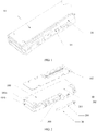
- the cable includes a strip line 10, a coaxial line 20, and a coupling ground plane 30.
- the coaxial line 20 is disposed in the coupling ground plane 30, a strip-line outer conductor of the strip line 10 is connected to the coupling ground plane 30, and a coaxial-line outer conductor of the coaxial line 20 is also connected to the coupling ground plane 30, so that the strip-line outer conductor and the coaxial-line outer conductor are electrically connected by using the coupling ground plane 30.
- the strip-line inner conductor and the coaxial-line inner conductor also are electrically connected in the cable, so that the cable can transmit a signal normally.
- FIG. 2 is an exploded view of the cable provided in FIG. 1 of the present invention.
- the cable includes the strip line, the coaxial line, and the coupling ground plane connecting the strip line and the coaxial line.
- a composition structure of the strip line is, in an outer-to-inner sequence, a strip-line outer conductor 100, a strip-line signal cavity 101 (the strip-line signal cavity 101 herein includes a signal cavity 101a and a signal cavity 101b), and a strip-line inner conductor 102.
- the strip-line inner conductor 102 is attached to a strip-line signal line supported printed circuit board (printed circuit board, PCB).
- the PCB is disposed in the strip-line signal cavity and is attached to an inner side of the strip-line outer conductor 100. It should also be noted that if the strip line has multiple strip-line signal cavities, each strip-line signal cavity is provided with a PCB, and a strip-line inner conductor is attached to the PCB. For ease of display, in this embodiment of the present invention, the PCB board is separately drawn outside the strip-line signal cavity in FIG. 2 . Optionally, the strip-line signal cavity 101 herein may include only one signal cavity.
- a composition structure of the coaxial line 20 is, in an outer-to-inner sequence, a coaxial-line outer conductor 200, a first insulation medium 201, and a coaxial-line inner conductor 202.
- the cable in the exploded view shown in FIG. 2 further includes the coupling ground plane 30, and a coupling aperture portion 300 penetrating the coupling ground plane 30 is disposed in the coupling ground plane 30.
- the coaxial line 20 is disposed in the coupling aperture portion 300 of the coupling ground plane 30.
- the coaxial line 20 is horizontally disposed in the coupling aperture portion 300
- the coaxial-line outer conductor 200 is coupled to the coupling ground plane 30
- the strip-line outer conductor 100 is connected to the coupling ground plane 30, that is, the coaxial-line outer conductor 200 is electrically connected to the strip-line outer conductor 100 by using the coupling ground plane 30.
- the coaxial line 20 penetrates the coupling ground plane 30, and the coaxial-line inner conductor 202 is also electrically connected to the strip-line inner conductor 102 on the PCB in the strip-line signal cavity 101.
- the strip line 10 is electrically connected to the coaxial line 20 entirely, so as to implement signal transmission.
- the coupling between the coaxial-line outer conductor 100 and the coupling ground plane 30 needs to meet a requirement that a high-frequency signal is fully grounded.
- connection between the strip-line outer conductor 100 and the coupling ground plane 30 may be various direct metal connections, such as welding connection or connection by using a screw.
- connection between the strip-line inner conductor and the coaxial-line inner conductor may also be various direct metal connections, such as welding connection or connection by using a screw.
- the strip-line outer conductor 100 and the coupling ground plane 30 are an integral metal piece.
- the strip-line outer conductor 100 may be coupled to the coaxial-line outer conductor 200, so that passive intermodulation interference in the prior art caused by mental contact, welding, or the like between the strip-line outer conductor and the coaxial-line outer conductor when the strip line and the coaxial line are interconnected can be reduced, and further, communications system quality is improved.
- FIG. 3 is an expansion diagram of a cross section of the coupling ground plane 30 and the coaxial line 20 disposed in the coupling aperture portion 300 of the coupling ground plane 30 in the cable shown in FIG. 1 in this embodiment of the present invention).
- the cable provided in this embodiment of the present invention further includes a second insulation medium 40.
- the second insulation medium 40 is disposed in the coupling ground plane 30, and is specifically disposed between the coaxial-line outer conductor 200 and the coupling aperture portion 300.
- the coupling aperture portion 300 is a cylindrical aperture portion.
- the coaxial-line outer conductor 200 may be coupled to the coupling ground plane 30 in a 360-degree manner, and it is ensured that the coaxial-line outer conductor 200 is relatively well coupled to the coupling ground plane 30.
- the coupling aperture portion 300 penetrates an axis of the coupling ground plane 30, so that when the coaxial line 20 is coupled to the coupling ground plane 30 by using the coupling aperture portion 300, a 360-degree uniform electric field is formed, and a relatively good effect is achieved.
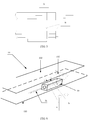
- the strip-line signal cavity 101 and the coupling ground plane 30 may be arranged in parallel, or may be arranged at an angle (as shown in FIG. 4 ).
- space in an antenna can be reduced.
- the strip-line signal cavity 101 and the coupling ground plane 30 are arranged at an angle, a manufacturing process can be simplified.
- the coaxial-line outer conductor in this embodiment of the present invention may be a coaxial-line outer conductor of the coaxial line itself, as shown in A (that is, a shadow region) in FIG. 5 , or may be an outer conductor formed by adding a 360-degree metal socket, as shown in B (that is, a shadow region) in FIG. 5 .
- the coaxial-line outer conductor includes two parts: the added metal socket and an outer conductor of the coaxial line itself.
- the cable provided in this embodiment of the present invention includes a strip line and a coaxial line.
- the coaxial line includes a coaxial-line outer conductor
- the strip line includes a strip-line outer conductor.
- the cable further includes a coupling ground plane provided with a coupling aperture portion.
- the coaxial line is disposed in the coupling aperture portion, the coaxial-line outer conductor is coupled to the coupling ground plane, the strip-line outer conductor is connected to the coupling ground plane, and a strip-line inner conductor is connected to a coaxial-line inner conductor, so that passive intermodulation interference caused by welding of the coaxial line to a ground block in the prior art can be reduced, and communication quality of a communications system can be improved.
- FIG. 6 is a cable according to another embodiment of the present invention.
- the cable includes a strip line 10 and a coaxial line 20.
- the strip line 10 includes a strip-line outer conductor 100 (divided into an upper ground and a lower ground in this embodiment), and the strip-line signal cavity 101, the strip-line inner conductor 102, the coaxial-line outer conductor 200, the first insulation medium 201, the coaxial-line inner conductor 202, the second insulation medium 40, and the coupling ground plane 30 that are shown in FIG. 1 to FIG. 5 .
- the coupling ground plane 30 is coupled to the coaxial-line outer conductor 200 in an approximately 360-degree manner, the coupling ground plane 30 is connected to a strip line grounding layer (that is, the strip-line outer conductor 100), and the coaxial-line inner conductor 202 is connected to the strip-line inner conductor 102.
- the coupling ground plane 30 and the strip-line outer conductor 100 exist independently, and then the upper and the lower grounding layers (that is, the strip-line outer conductor 100) of the strip line are connected to the coupling ground plane 30 by using screws (as shown in a and b in FIG. 6 ).
- the coupling ground plane 30 and the strip line 10 are physically designed separately, and the coupling ground plane 30 and the strip line 10 are connected by using a screw, so as to partially reduce passive intermodulation interference.
- welding of the coaxial-line outer conductor to a ground block is saved.
- the cable provided in this embodiment of the present invention includes the strip line and the coaxial line.
- the coaxial line includes the coaxial-line outer conductor
- the strip line includes the strip-line outer conductor.
- the cable further includes the coupling ground plane provided with the coupling aperture portion.
- the coaxial line is disposed in the coupling aperture portion, the coaxial-line outer conductor is coupled to the coupling ground plane, the strip-line outer conductor is connected to the coupling ground plane, and the strip-line inner conductor is connected to the coaxial-line inner conductor, so that passive intermodulation interference caused by welding of the coaxial line to a ground block in the prior art can be reduced, and communication quality of a communications system can be improved.
- phase shifter apparatus provides a phase shifter apparatus.
- the phase shifter apparatus includes the strip line 10, the coaxial line 20, and the coupling ground plane 30.
- the coupling ground plane 30 is coupled to the coaxial-line outer conductor in an approximately 360-degree manner, the coupling ground plane 30 is connected to a strip-line grounding layer, and the coaxial-line inner conductor is connected to the strip-line inner conductor.
- the coupling ground plane and the strip-line outer conductor are integrated, that is, the coupling ground plane and the strip-line outer conductor are one metal piece, or may be a material that is obtained by electroplating a plastic and that may be used as a metal piece for a high-frequency signal.
- a strip-line signal cavity and a coupling aperture portion are formed by means of integrated pultrusion by using a special technology.
- the phase shifter apparatus provided in this embodiment of the present invention is applied to a base station antenna system.
- a base station antenna is usually in a dual-polarized design, each polarization requires a phase shifter, and phase shifters of the base station antenna appear in pairs. Therefore, in this embodiment, strip lines used by the phase shifter apparatus are arranged in an up and down manner, and share one grounding layer, so as to reduce space occupied by the two phase shifters.
- the coupling aperture portion and the strip-line signal cavity are arranged in parallel, so as to further reduce a size of a phase shifter.
- An inner design of the phase shifter may be in two manners: First, a phase is changed by means of medium sliding; second, a phase is changed by changing a physical length of a circuit.
- the second manner is used, that is, a physical length relative to a fixed PCB is changed by pulling and sliding a PCB, to implement a phase shift.
- a principle of the phase shifter is not described in detail herein.
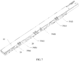
- the phase shifter provided in this embodiment of the present invention is a one-input-five-output lumped phase shifter (as shown in FIG. 7 ).
- the phase shifter includes six coaxial lines.
- the six coaxial lines are sequentially disposed in six coupling ground planes: 30(a), 30(b), 30(c), 30(d), 30(e), and 30(f).
- the six coaxial lines may be connected to the strip line 10 in any manner shown in FIG. 1 to FIG. 6 .
- a signal is coupled and input by using the coaxial line disposed in the coupling ground plane 30(d), and then is coupled and output by using the coaxial lines disposed in the coupling ground planes 30(a), 30(b), 30(c), 30(e), and 30(f).
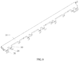
- FIG. 8 shows another phase shifter apparatus according to an embodiment of the present invention.
- the phase shifter apparatus includes a strip line 10, a coaxial line 20, a second insulation medium, and a coupling ground plane 30.
- the coupling ground plane 30 is coupled to a coaxial-line outer conductor in an approximately 360-degree manner, a coupling ground plane is connected to a strip-line grounding layer, and a coaxial-line inner conductor is connected to a strip-line inner conductor.
- the coupling ground plane and a strip-line outer conductor are integrated, that is, the coupling ground plane and the strip-line outer conductor are one metal piece, or may be a material that is obtained by electroplating a plastic and that may be used as a metal piece for a high-frequency signal.
- a strip-line signal cavity and a coupling aperture portion are formed by means of integrated pultrusion by using a special technology.
- the strip lines used by the phase shifter apparatus are arranged in an up and down manner, and share one grounding layer, so as to reduce space occupied by the two phase shifters.
- the coupling aperture portion is perpendicular to the strip-line signal cavity (that is, a 90-degree angle is formed), so that complexity of assembling the strip line and the coaxial line can be reduced, and the strip line and the coaxial line can be assembled conveniently.
- the phase shifter apparatus provided in this embodiment of the present invention is a one-input-nine-output phase shifter.
- the phase shifter includes a PCB circuit board and a medium capable of sliding along a medium movement direction.
- the medium slides along an indicated movement direction, an electrical length between an input port and each output port is adjusted according to a requirement, and output ports are connected to a radiating element of an array antenna by using the coaxial line, so that a high-frequency signal at the input port is coupled to the coaxial line by using the strip line, and then forms an electromagnetic wave in the radiating element to radiate out, so as to perform space radio transmission.
- the coupling aperture portion and the strip-line signal cavity of the phase shifter are not arranged in parallel, but arranged at an angle. Specifically, the coupling aperture portion and the strip-line signal cavity form a 90-degree angle. In this way, the phase shifter may be simply assembled.
- phase shifter provided in this embodiment of the present invention uses any cable described in the foregoing embodiments.
- passive intermodulation interference caused by welding connection or screw connection between a coaxial-line outer conductor and a strip-line outer conductor is reduced, and communication quality of a communications system is improved.
- the cable provided in this embodiment of the present invention not only may be applied to a phase shifter apparatus, but also may be applied to another high-frequency device such as a filter. This is not limited in the present invention.
Landscapes
- Communication Cables (AREA)
- Waveguide Aerials (AREA)
Claims (4)
- Appareil déphaseur, comprenant une ligne ruban (10) et une ligne coaxiale (20), la ligne ruban (10) comprenant, dans une séquence de l'extérieur vers l'intérieur, un conducteur externe de ligne ruban (100), une cavité de signal de ligne ruban (101) et un conducteur interne de ligne ruban (102), et la ligne coaxiale (20) comprenant, dans une séquence de l'extérieur vers l'intérieur, un conducteur externe de ligne coaxiale (200), un premier milieu d'isolation (201) et un conducteur interne de ligne coaxiale (202) ; et l'appareil déphaseur comprenant en outre un plan de masse de couplage (30), le conducteur externe de ligne coaxiale (200) étant un cylindre, le conducteur externe de ligne ruban (100) et le plan de masse de couplage (30) constituant une pièce métallique intégrale, et une partie d'ouverture de couplage (300) pénétrant dans le plan de masse de couplage (30) étant disposée dans le plan de masse de couplage (30),
dans lequel le plan de masse de couplage (30) s'étend dans une direction de la ligne coaxiale (20), la partie d'ouverture de couplage (300) est une partie d'ouverture cylindrique s'étendant le long d'un axe longitudinal du plan de masse de couplage (30), la ligne coaxiale (20) est disposée dans la partie d'ouverture de couplage (300) du plan de masse de couplage (30) et pénètre dans la pièce métallique intégrale formant le plan de masse de couplage (30), le conducteur externe de ligne coaxiale (200) est relié électriquement au conducteur externe de ligne ruban (100) au moyen du plan de masse de couplage (30), et le conducteur interne de ligne coaxiale (202) est relié électriquement au conducteur interne de ligne ruban (102). - Appareil déphaseur selon la revendication 1, l'appareil déphaseur comprenant en outre un deuxième milieu d'isolation (40), et le deuxième milieu d'isolation (40) étant disposé entre le conducteur externe de ligne coaxiale (200) et le plan de masse de couplage (30).
- Appareil déphaseur selon la revendication 1 ou 2, dans lequel des directions principales d'extension de la cavité de signal de ligne ruban (101) et du plan de masse de couplage (30) sont disposées en parallèle.
- Appareil déphaseur selon la revendication 1 ou 2, dans lequel des directions principales d'extension de la cavité de signal de ligne ruban (101) et de la partie d'ouverture de couplage (300) forment un angle de 90 degrés.
Applications Claiming Priority (1)
| Application Number | Priority Date | Filing Date | Title |
|---|---|---|---|
| PCT/CN2015/080418 WO2016191988A1 (fr) | 2015-05-29 | 2015-05-29 | Câble et dispositif haute fréquence l'utilisant |
Publications (3)
| Publication Number | Publication Date |
|---|---|
| EP3297092A1 EP3297092A1 (fr) | 2018-03-21 |
| EP3297092A4 EP3297092A4 (fr) | 2018-05-02 |
| EP3297092B1 true EP3297092B1 (fr) | 2020-02-05 |
Family
ID=57439807
Family Applications (1)
| Application Number | Title | Priority Date | Filing Date |
|---|---|---|---|
| EP15893651.8A Active EP3297092B1 (fr) | 2015-05-29 | 2015-05-29 | Câble et dispositif haute fréquence l'utilisant |
Country Status (4)
| Country | Link |
|---|---|
| US (1) | US10505251B2 (fr) |
| EP (1) | EP3297092B1 (fr) |
| CN (1) | CN106575809A (fr) |
| WO (1) | WO2016191988A1 (fr) |
Families Citing this family (3)
| Publication number | Priority date | Publication date | Assignee | Title |
|---|---|---|---|---|
| CN107634290A (zh) * | 2017-08-28 | 2018-01-26 | 广州司南天线设计研究所有限公司 | 一种新型耦合移相器 |
| CN108461875A (zh) * | 2018-03-29 | 2018-08-28 | 广东通宇通讯股份有限公司 | 一种移相器 |
| CN113540734B (zh) * | 2020-04-22 | 2022-09-02 | 大富科技(安徽)股份有限公司 | 一种耦合装置及通信设备 |
Family Cites Families (18)
| Publication number | Priority date | Publication date | Assignee | Title |
|---|---|---|---|---|
| US4346355A (en) * | 1980-11-17 | 1982-08-24 | Raytheon Company | Radio frequency energy launcher |
| JPH07240245A (ja) * | 1994-02-25 | 1995-09-12 | Matsushita Electric Ind Co Ltd | 同軸線接続機器と同軸ケーブルの接続方法 |
| US5613859A (en) * | 1995-11-28 | 1997-03-25 | Watkins-Johnson Company | Connector asembly for detachably connecting a printed wiring board to a coaxial transmission lines connector |
| GB2308511B (en) * | 1995-12-21 | 2000-03-29 | Fringe Electronics Ltd | Screening can |
| US5628057A (en) * | 1996-03-05 | 1997-05-06 | Motorola, Inc. | Multi-port radio frequency signal transformation network |
| US6236287B1 (en) * | 1999-05-12 | 2001-05-22 | Raytheon Company | Wideband shielded coaxial to microstrip orthogonal launcher using distributed discontinuities |
| US6366185B1 (en) * | 2000-01-12 | 2002-04-02 | Raytheon Company | Vertical interconnect between coaxial or GCPW circuits and airline via compressible center conductors |
| DE102004043518B3 (de) | 2004-09-08 | 2006-05-18 | Kathrein-Werke Kg | Vorrichtung zum Anschluss eines Koaxialkabels an ein Gehäuse |
| JP2008078720A (ja) * | 2006-09-19 | 2008-04-03 | Mitsumi Electric Co Ltd | アンテナ装置 |
| FR2942569B1 (fr) * | 2009-02-25 | 2011-03-25 | Alcatel Lucent | Dispositif de connexion pour un cable coaxial transportant un signal haute frequence. |
| CN102569949A (zh) * | 2010-12-09 | 2012-07-11 | 中国航天科工集团第二研究院二十三所 | 一种毫米波波段微带-同轴线转换装置 |
| CN102157767B (zh) | 2011-03-28 | 2014-06-11 | 京信通信系统(中国)有限公司 | 同轴介质移相系统、移相器及移相驱动装置 |
| CN202797223U (zh) * | 2011-09-27 | 2013-03-13 | 上海无线电设备研究所 | 一种带状线与同轴连接器转换结构 |
| US9054403B2 (en) * | 2012-06-21 | 2015-06-09 | Raytheon Company | Coaxial-to-stripline and stripline-to-stripline transitions including a shorted center via |
| CN103414010A (zh) * | 2013-08-05 | 2013-11-27 | 珠海德百祺科技有限公司 | 天线 |
| CN104037474B (zh) * | 2014-01-28 | 2017-05-10 | 京信通信技术(广州)有限公司 | 一种腔体式移相器 |
| CN203826529U (zh) * | 2014-04-10 | 2014-09-10 | 江苏捷士通射频系统有限公司 | 一种同轴电缆与带状线转接器 |
| CN104466405A (zh) * | 2014-11-11 | 2015-03-25 | 李梓萌 | 一种阵列天线可调移相装置 |
-
2015
- 2015-05-29 CN CN201580044364.2A patent/CN106575809A/zh active Pending
- 2015-05-29 EP EP15893651.8A patent/EP3297092B1/fr active Active
- 2015-05-29 WO PCT/CN2015/080418 patent/WO2016191988A1/fr active Application Filing
-
2017
- 2017-11-28 US US15/824,895 patent/US10505251B2/en active Active
Non-Patent Citations (1)
| Title |
|---|
| None * |
Also Published As
| Publication number | Publication date |
|---|---|
| EP3297092A4 (fr) | 2018-05-02 |
| US10505251B2 (en) | 2019-12-10 |
| EP3297092A1 (fr) | 2018-03-21 |
| CN106575809A (zh) | 2017-04-19 |
| WO2016191988A1 (fr) | 2016-12-08 |
| US20180083335A1 (en) | 2018-03-22 |
Similar Documents
| Publication | Publication Date | Title |
|---|---|---|
| CN109802234B (zh) | 基站天线及移相馈电装置 | |
| CN109638457B (zh) | 天线及移相馈电装置 | |
| US9325043B2 (en) | Phase shifting circuit including an elongated conductive path covered by a metal sheet having stand-off feet and also including a slidable tuning member | |
| US10833461B2 (en) | Connectors for coaxial cables | |
| WO2019128218A1 (fr) | Structure de déphasage et antenne | |
| WO2020155723A1 (fr) | Appareil d'alimentation à déphasage et antenne de station de base | |
| EP3297092B1 (fr) | Câble et dispositif haute fréquence l'utilisant | |
| JP6557732B2 (ja) | 移動通信基地局のアンテナ装置内の信号分配/結合装置 | |
| US8125292B2 (en) | Coaxial line to planar RF transmission line transition using a microstrip portion of greater width than the RF transmission line | |
| CN210692765U (zh) | 移相馈电装置、辐射阵列及大规模阵列天线 | |
| US20230057120A1 (en) | Wireless radio units that include antenna systems having coaxial feed cables that are selectively connected to an rf ground plane | |
| CN112290171B (zh) | 同轴电缆和带状线的连接装置及其组装方法和高频设备 | |
| CN213150976U (zh) | 同轴电缆和带状线的连接装置和高频设备 | |
| US6956449B2 (en) | Quadrature hybrid low loss directional coupler | |
| WO2022256099A1 (fr) | Connecteur et procédé pour connecter un câble coaxial à une carte de circuit imprimé | |
| WO2021238210A1 (fr) | Déphaseur intégré à alimentation et antenne utilisant celui-ci | |
| CN210430036U (zh) | 腔体移相器以及基站天线 | |
| JPH07263887A (ja) | マイクロ波回路装置 | |
| EP3249741B1 (fr) | Dispositif pour la connexion entre une ligne ruban et un câble coaxial | |
| CN113745775A (zh) | 集成馈电器的移相器及应用其的天线 | |
| CN111063998A (zh) | 天线及馈电校准网络装置 | |
| EP3046179B1 (fr) | Appareil de filtre céramique et son procédé d'utilisation | |
| US20230064306A1 (en) | Connection assembly for antenna and base station antenna | |
| CN210957005U (zh) | 天线及馈电校准网络装置 | |
| CN114221108B (zh) | 传输装置 |
Legal Events
| Date | Code | Title | Description |
|---|---|---|---|
| STAA | Information on the status of an ep patent application or granted ep patent |
Free format text: STATUS: THE INTERNATIONAL PUBLICATION HAS BEEN MADE |
|
| PUAI | Public reference made under article 153(3) epc to a published international application that has entered the european phase |
Free format text: ORIGINAL CODE: 0009012 |
|
| STAA | Information on the status of an ep patent application or granted ep patent |
Free format text: STATUS: REQUEST FOR EXAMINATION WAS MADE |
|
| 17P | Request for examination filed |
Effective date: 20171208 |
|
| AK | Designated contracting states |
Kind code of ref document: A1 Designated state(s): AL AT BE BG CH CY CZ DE DK EE ES FI FR GB GR HR HU IE IS IT LI LT LU LV MC MK MT NL NO PL PT RO RS SE SI SK SM TR |
|
| AX | Request for extension of the european patent |
Extension state: BA ME |
|
| A4 | Supplementary search report drawn up and despatched |
Effective date: 20180406 |
|
| RIC1 | Information provided on ipc code assigned before grant |
Ipc: H01P 5/08 20060101AFI20180329BHEP Ipc: H01R 4/02 20060101ALI20180329BHEP Ipc: H01P 5/02 20060101ALI20180329BHEP Ipc: H01R 4/06 20060101ALI20180329BHEP Ipc: H01P 3/08 20060101ALI20180329BHEP Ipc: H01R 9/05 20060101ALI20180329BHEP |
|
| DAV | Request for validation of the european patent (deleted) | ||
| DAX | Request for extension of the european patent (deleted) | ||
| STAA | Information on the status of an ep patent application or granted ep patent |
Free format text: STATUS: EXAMINATION IS IN PROGRESS |
|
| 17Q | First examination report despatched |
Effective date: 20190311 |
|
| GRAP | Despatch of communication of intention to grant a patent |
Free format text: ORIGINAL CODE: EPIDOSNIGR1 |
|
| STAA | Information on the status of an ep patent application or granted ep patent |
Free format text: STATUS: GRANT OF PATENT IS INTENDED |
|
| RIC1 | Information provided on ipc code assigned before grant |
Ipc: H01P 5/08 20060101AFI20190823BHEP Ipc: H01P 3/08 20060101ALI20190823BHEP Ipc: H01R 9/05 20060101ALI20190823BHEP Ipc: H01P 1/18 20060101ALI20190823BHEP |
|
| INTG | Intention to grant announced |
Effective date: 20190927 |
|
| GRAS | Grant fee paid |
Free format text: ORIGINAL CODE: EPIDOSNIGR3 |
|
| GRAA | (expected) grant |
Free format text: ORIGINAL CODE: 0009210 |
|
| STAA | Information on the status of an ep patent application or granted ep patent |
Free format text: STATUS: THE PATENT HAS BEEN GRANTED |
|
| AK | Designated contracting states |
Kind code of ref document: B1 Designated state(s): AL AT BE BG CH CY CZ DE DK EE ES FI FR GB GR HR HU IE IS IT LI LT LU LV MC MK MT NL NO PL PT RO RS SE SI SK SM TR |
|
| REG | Reference to a national code |
Ref country code: GB Ref legal event code: FG4D |
|
| REG | Reference to a national code |
Ref country code: AT Ref legal event code: REF Ref document number: 1230509 Country of ref document: AT Kind code of ref document: T Effective date: 20200215 |
|
| REG | Reference to a national code |
Ref country code: DE Ref legal event code: R096 Ref document number: 602015046615 Country of ref document: DE |
|
| REG | Reference to a national code |
Ref country code: IE Ref legal event code: FG4D |
|
| REG | Reference to a national code |
Ref country code: CH Ref legal event code: EP |
|
| REG | Reference to a national code |
Ref country code: NL Ref legal event code: MP Effective date: 20200205 |
|
| PG25 | Lapsed in a contracting state [announced via postgrant information from national office to epo] |
Ref country code: PT Free format text: LAPSE BECAUSE OF FAILURE TO SUBMIT A TRANSLATION OF THE DESCRIPTION OR TO PAY THE FEE WITHIN THE PRESCRIBED TIME-LIMIT Effective date: 20200628 Ref country code: FI Free format text: LAPSE BECAUSE OF FAILURE TO SUBMIT A TRANSLATION OF THE DESCRIPTION OR TO PAY THE FEE WITHIN THE PRESCRIBED TIME-LIMIT Effective date: 20200205 Ref country code: RS Free format text: LAPSE BECAUSE OF FAILURE TO SUBMIT A TRANSLATION OF THE DESCRIPTION OR TO PAY THE FEE WITHIN THE PRESCRIBED TIME-LIMIT Effective date: 20200205 Ref country code: NO Free format text: LAPSE BECAUSE OF FAILURE TO SUBMIT A TRANSLATION OF THE DESCRIPTION OR TO PAY THE FEE WITHIN THE PRESCRIBED TIME-LIMIT Effective date: 20200505 |
|
| REG | Reference to a national code |
Ref country code: LT Ref legal event code: MG4D |
|
| PG25 | Lapsed in a contracting state [announced via postgrant information from national office to epo] |
Ref country code: BG Free format text: LAPSE BECAUSE OF FAILURE TO SUBMIT A TRANSLATION OF THE DESCRIPTION OR TO PAY THE FEE WITHIN THE PRESCRIBED TIME-LIMIT Effective date: 20200505 Ref country code: HR Free format text: LAPSE BECAUSE OF FAILURE TO SUBMIT A TRANSLATION OF THE DESCRIPTION OR TO PAY THE FEE WITHIN THE PRESCRIBED TIME-LIMIT Effective date: 20200205 Ref country code: IS Free format text: LAPSE BECAUSE OF FAILURE TO SUBMIT A TRANSLATION OF THE DESCRIPTION OR TO PAY THE FEE WITHIN THE PRESCRIBED TIME-LIMIT Effective date: 20200605 Ref country code: LV Free format text: LAPSE BECAUSE OF FAILURE TO SUBMIT A TRANSLATION OF THE DESCRIPTION OR TO PAY THE FEE WITHIN THE PRESCRIBED TIME-LIMIT Effective date: 20200205 Ref country code: SE Free format text: LAPSE BECAUSE OF FAILURE TO SUBMIT A TRANSLATION OF THE DESCRIPTION OR TO PAY THE FEE WITHIN THE PRESCRIBED TIME-LIMIT Effective date: 20200205 Ref country code: GR Free format text: LAPSE BECAUSE OF FAILURE TO SUBMIT A TRANSLATION OF THE DESCRIPTION OR TO PAY THE FEE WITHIN THE PRESCRIBED TIME-LIMIT Effective date: 20200506 |
|
| PG25 | Lapsed in a contracting state [announced via postgrant information from national office to epo] |
Ref country code: NL Free format text: LAPSE BECAUSE OF FAILURE TO SUBMIT A TRANSLATION OF THE DESCRIPTION OR TO PAY THE FEE WITHIN THE PRESCRIBED TIME-LIMIT Effective date: 20200205 |
|
| PG25 | Lapsed in a contracting state [announced via postgrant information from national office to epo] |
Ref country code: DK Free format text: LAPSE BECAUSE OF FAILURE TO SUBMIT A TRANSLATION OF THE DESCRIPTION OR TO PAY THE FEE WITHIN THE PRESCRIBED TIME-LIMIT Effective date: 20200205 Ref country code: SM Free format text: LAPSE BECAUSE OF FAILURE TO SUBMIT A TRANSLATION OF THE DESCRIPTION OR TO PAY THE FEE WITHIN THE PRESCRIBED TIME-LIMIT Effective date: 20200205 Ref country code: SK Free format text: LAPSE BECAUSE OF FAILURE TO SUBMIT A TRANSLATION OF THE DESCRIPTION OR TO PAY THE FEE WITHIN THE PRESCRIBED TIME-LIMIT Effective date: 20200205 Ref country code: EE Free format text: LAPSE BECAUSE OF FAILURE TO SUBMIT A TRANSLATION OF THE DESCRIPTION OR TO PAY THE FEE WITHIN THE PRESCRIBED TIME-LIMIT Effective date: 20200205 Ref country code: RO Free format text: LAPSE BECAUSE OF FAILURE TO SUBMIT A TRANSLATION OF THE DESCRIPTION OR TO PAY THE FEE WITHIN THE PRESCRIBED TIME-LIMIT Effective date: 20200205 Ref country code: CZ Free format text: LAPSE BECAUSE OF FAILURE TO SUBMIT A TRANSLATION OF THE DESCRIPTION OR TO PAY THE FEE WITHIN THE PRESCRIBED TIME-LIMIT Effective date: 20200205 Ref country code: LT Free format text: LAPSE BECAUSE OF FAILURE TO SUBMIT A TRANSLATION OF THE DESCRIPTION OR TO PAY THE FEE WITHIN THE PRESCRIBED TIME-LIMIT Effective date: 20200205 Ref country code: ES Free format text: LAPSE BECAUSE OF FAILURE TO SUBMIT A TRANSLATION OF THE DESCRIPTION OR TO PAY THE FEE WITHIN THE PRESCRIBED TIME-LIMIT Effective date: 20200205 |
|
| REG | Reference to a national code |
Ref country code: DE Ref legal event code: R097 Ref document number: 602015046615 Country of ref document: DE |
|
| REG | Reference to a national code |
Ref country code: AT Ref legal event code: MK05 Ref document number: 1230509 Country of ref document: AT Kind code of ref document: T Effective date: 20200205 |
|
| REG | Reference to a national code |
Ref country code: DE Ref legal event code: R119 Ref document number: 602015046615 Country of ref document: DE |
|
| PLBE | No opposition filed within time limit |
Free format text: ORIGINAL CODE: 0009261 |
|
| STAA | Information on the status of an ep patent application or granted ep patent |
Free format text: STATUS: NO OPPOSITION FILED WITHIN TIME LIMIT |
|
| 26N | No opposition filed |
Effective date: 20201106 |
|
| PG25 | Lapsed in a contracting state [announced via postgrant information from national office to epo] |
Ref country code: AT Free format text: LAPSE BECAUSE OF FAILURE TO SUBMIT A TRANSLATION OF THE DESCRIPTION OR TO PAY THE FEE WITHIN THE PRESCRIBED TIME-LIMIT Effective date: 20200205 Ref country code: LI Free format text: LAPSE BECAUSE OF NON-PAYMENT OF DUE FEES Effective date: 20200531 Ref country code: IT Free format text: LAPSE BECAUSE OF FAILURE TO SUBMIT A TRANSLATION OF THE DESCRIPTION OR TO PAY THE FEE WITHIN THE PRESCRIBED TIME-LIMIT Effective date: 20200205 Ref country code: MC Free format text: LAPSE BECAUSE OF FAILURE TO SUBMIT A TRANSLATION OF THE DESCRIPTION OR TO PAY THE FEE WITHIN THE PRESCRIBED TIME-LIMIT Effective date: 20200205 Ref country code: CH Free format text: LAPSE BECAUSE OF NON-PAYMENT OF DUE FEES Effective date: 20200531 |
|
| PG25 | Lapsed in a contracting state [announced via postgrant information from national office to epo] |
Ref country code: PL Free format text: LAPSE BECAUSE OF FAILURE TO SUBMIT A TRANSLATION OF THE DESCRIPTION OR TO PAY THE FEE WITHIN THE PRESCRIBED TIME-LIMIT Effective date: 20200205 Ref country code: SI Free format text: LAPSE BECAUSE OF FAILURE TO SUBMIT A TRANSLATION OF THE DESCRIPTION OR TO PAY THE FEE WITHIN THE PRESCRIBED TIME-LIMIT Effective date: 20200205 |
|
| REG | Reference to a national code |
Ref country code: BE Ref legal event code: MM Effective date: 20200531 |
|
| PG25 | Lapsed in a contracting state [announced via postgrant information from national office to epo] |
Ref country code: LU Free format text: LAPSE BECAUSE OF NON-PAYMENT OF DUE FEES Effective date: 20200529 |
|
| PG25 | Lapsed in a contracting state [announced via postgrant information from national office to epo] |
Ref country code: IE Free format text: LAPSE BECAUSE OF NON-PAYMENT OF DUE FEES Effective date: 20200529 Ref country code: FR Free format text: LAPSE BECAUSE OF NON-PAYMENT OF DUE FEES Effective date: 20200531 |
|
| PG25 | Lapsed in a contracting state [announced via postgrant information from national office to epo] |
Ref country code: BE Free format text: LAPSE BECAUSE OF NON-PAYMENT OF DUE FEES Effective date: 20200531 Ref country code: DE Free format text: LAPSE BECAUSE OF NON-PAYMENT OF DUE FEES Effective date: 20201201 |
|
| PG25 | Lapsed in a contracting state [announced via postgrant information from national office to epo] |
Ref country code: TR Free format text: LAPSE BECAUSE OF FAILURE TO SUBMIT A TRANSLATION OF THE DESCRIPTION OR TO PAY THE FEE WITHIN THE PRESCRIBED TIME-LIMIT Effective date: 20200205 Ref country code: MT Free format text: LAPSE BECAUSE OF FAILURE TO SUBMIT A TRANSLATION OF THE DESCRIPTION OR TO PAY THE FEE WITHIN THE PRESCRIBED TIME-LIMIT Effective date: 20200205 Ref country code: CY Free format text: LAPSE BECAUSE OF FAILURE TO SUBMIT A TRANSLATION OF THE DESCRIPTION OR TO PAY THE FEE WITHIN THE PRESCRIBED TIME-LIMIT Effective date: 20200205 |
|
| PG25 | Lapsed in a contracting state [announced via postgrant information from national office to epo] |
Ref country code: MK Free format text: LAPSE BECAUSE OF FAILURE TO SUBMIT A TRANSLATION OF THE DESCRIPTION OR TO PAY THE FEE WITHIN THE PRESCRIBED TIME-LIMIT Effective date: 20200205 Ref country code: AL Free format text: LAPSE BECAUSE OF FAILURE TO SUBMIT A TRANSLATION OF THE DESCRIPTION OR TO PAY THE FEE WITHIN THE PRESCRIBED TIME-LIMIT Effective date: 20200205 |
|
| PGFP | Annual fee paid to national office [announced via postgrant information from national office to epo] |
Ref country code: GB Payment date: 20230406 Year of fee payment: 9 |