EP3296836B1 - Computer device and data read-write method for computer device - Google Patents
Computer device and data read-write method for computer device Download PDFInfo
- Publication number
- EP3296836B1 EP3296836B1 EP15898652.1A EP15898652A EP3296836B1 EP 3296836 B1 EP3296836 B1 EP 3296836B1 EP 15898652 A EP15898652 A EP 15898652A EP 3296836 B1 EP3296836 B1 EP 3296836B1
- Authority
- EP
- European Patent Office
- Prior art keywords
- read
- queue module
- write
- network device
- data
- Prior art date
- Legal status (The legal status is an assumption and is not a legal conclusion. Google has not performed a legal analysis and makes no representation as to the accuracy of the status listed.)
- Active
Links
- 238000000034 method Methods 0.000 title claims description 35
- 230000004044 response Effects 0.000 claims description 283
- 230000005540 biological transmission Effects 0.000 claims description 175
- 230000001960 triggered effect Effects 0.000 claims description 24
- 238000012545 processing Methods 0.000 claims description 17
- 230000015654 memory Effects 0.000 description 41
- 238000004891 communication Methods 0.000 description 16
- 238000010586 diagram Methods 0.000 description 7
- 230000008569 process Effects 0.000 description 7
- 238000005516 engineering process Methods 0.000 description 6
- 102100022584 3-keto-steroid reductase/17-beta-hydroxysteroid dehydrogenase 7 Human genes 0.000 description 4
- 101710135980 3-keto-steroid reductase/17-beta-hydroxysteroid dehydrogenase 7 Proteins 0.000 description 4
- 230000008878 coupling Effects 0.000 description 3
- 238000010168 coupling process Methods 0.000 description 3
- 238000005859 coupling reaction Methods 0.000 description 3
- 230000006870 function Effects 0.000 description 3
- 238000011176 pooling Methods 0.000 description 3
- 239000002699 waste material Substances 0.000 description 3
- XUIMIQQOPSSXEZ-UHFFFAOYSA-N Silicon Chemical compound [Si] XUIMIQQOPSSXEZ-UHFFFAOYSA-N 0.000 description 2
- 238000013507 mapping Methods 0.000 description 2
- 229910052710 silicon Inorganic materials 0.000 description 2
- 239000010703 silicon Substances 0.000 description 2
- 238000013461 design Methods 0.000 description 1
- 238000011161 development Methods 0.000 description 1
- 230000006872 improvement Effects 0.000 description 1
- 239000000203 mixture Substances 0.000 description 1
- 230000003287 optical effect Effects 0.000 description 1
- 230000002093 peripheral effect Effects 0.000 description 1
- 238000013468 resource allocation Methods 0.000 description 1
Images


Classifications
-
- G—PHYSICS
- G06—COMPUTING; CALCULATING OR COUNTING
- G06F—ELECTRIC DIGITAL DATA PROCESSING
- G06F3/00—Input arrangements for transferring data to be processed into a form capable of being handled by the computer; Output arrangements for transferring data from processing unit to output unit, e.g. interface arrangements
- G06F3/06—Digital input from, or digital output to, record carriers, e.g. RAID, emulated record carriers or networked record carriers
- G06F3/0601—Interfaces specially adapted for storage systems
- G06F3/0602—Interfaces specially adapted for storage systems specifically adapted to achieve a particular effect
- G06F3/061—Improving I/O performance
-
- H—ELECTRICITY
- H04—ELECTRIC COMMUNICATION TECHNIQUE
- H04L—TRANSMISSION OF DIGITAL INFORMATION, e.g. TELEGRAPHIC COMMUNICATION
- H04L69/00—Network arrangements, protocols or services independent of the application payload and not provided for in the other groups of this subclass
- H04L69/10—Streamlined, light-weight or high-speed protocols, e.g. express transfer protocol [XTP] or byte stream
-
- G—PHYSICS
- G06—COMPUTING; CALCULATING OR COUNTING
- G06F—ELECTRIC DIGITAL DATA PROCESSING
- G06F1/00—Details not covered by groups G06F3/00 - G06F13/00 and G06F21/00
- G06F1/16—Constructional details or arrangements
-
- G—PHYSICS
- G06—COMPUTING; CALCULATING OR COUNTING
- G06F—ELECTRIC DIGITAL DATA PROCESSING
- G06F13/00—Interconnection of, or transfer of information or other signals between, memories, input/output devices or central processing units
- G06F13/14—Handling requests for interconnection or transfer
- G06F13/20—Handling requests for interconnection or transfer for access to input/output bus
- G06F13/32—Handling requests for interconnection or transfer for access to input/output bus using combination of interrupt and burst mode transfer
-
- G—PHYSICS
- G06—COMPUTING; CALCULATING OR COUNTING
- G06F—ELECTRIC DIGITAL DATA PROCESSING
- G06F3/00—Input arrangements for transferring data to be processed into a form capable of being handled by the computer; Output arrangements for transferring data from processing unit to output unit, e.g. interface arrangements
- G06F3/06—Digital input from, or digital output to, record carriers, e.g. RAID, emulated record carriers or networked record carriers
- G06F3/0601—Interfaces specially adapted for storage systems
- G06F3/0602—Interfaces specially adapted for storage systems specifically adapted to achieve a particular effect
- G06F3/061—Improving I/O performance
- G06F3/0611—Improving I/O performance in relation to response time
-
- G—PHYSICS
- G06—COMPUTING; CALCULATING OR COUNTING
- G06F—ELECTRIC DIGITAL DATA PROCESSING
- G06F3/00—Input arrangements for transferring data to be processed into a form capable of being handled by the computer; Output arrangements for transferring data from processing unit to output unit, e.g. interface arrangements
- G06F3/06—Digital input from, or digital output to, record carriers, e.g. RAID, emulated record carriers or networked record carriers
- G06F3/0601—Interfaces specially adapted for storage systems
- G06F3/0628—Interfaces specially adapted for storage systems making use of a particular technique
- G06F3/0655—Vertical data movement, i.e. input-output transfer; data movement between one or more hosts and one or more storage devices
- G06F3/0659—Command handling arrangements, e.g. command buffers, queues, command scheduling
-
- G—PHYSICS
- G06—COMPUTING; CALCULATING OR COUNTING
- G06F—ELECTRIC DIGITAL DATA PROCESSING
- G06F3/00—Input arrangements for transferring data to be processed into a form capable of being handled by the computer; Output arrangements for transferring data from processing unit to output unit, e.g. interface arrangements
- G06F3/06—Digital input from, or digital output to, record carriers, e.g. RAID, emulated record carriers or networked record carriers
- G06F3/0601—Interfaces specially adapted for storage systems
- G06F3/0668—Interfaces specially adapted for storage systems adopting a particular infrastructure
- G06F3/067—Distributed or networked storage systems, e.g. storage area networks [SAN], network attached storage [NAS]
-
- H—ELECTRICITY
- H04—ELECTRIC COMMUNICATION TECHNIQUE
- H04L—TRANSMISSION OF DIGITAL INFORMATION, e.g. TELEGRAPHIC COMMUNICATION
- H04L69/00—Network arrangements, protocols or services independent of the application payload and not provided for in the other groups of this subclass
- H04L69/02—Protocol performance
Definitions
- the present invention relates to the field of information technologies, and in particular, to a computer device and a method for reading/writing data by a computer device.
- a data center architecture has developed into a virtualization-technology-centered architecture from a tightly coupled siloed server architecture.
- the challenges include P bits/second real-time data processing, dynamic resource allocation and adjustment on demand, energy efficiency improvement of a large-scale system, or the like.
- a high-throughput computer data center with features such as resource pooling, hardware decoupling, and silicon photonic interconnection comes into being.
- a high-throughput computing node is connected to a memory resource pool or an input/output resource pool by using a network, to dynamically allocate and adjust resources and improve system energy efficiency.
- resource pooling hardware decoupling makes an interconnect technology, for example, silicon photonic interconnection, become a most crucial technology.
- a current data center level interconnect technology relies mainly on an Ethernet interconnect technology.
- the interconnect technology becomes less capable of meeting a requirement of a data center on quick and high-capacity data exchange, while a simplified resource pooling-centered interconnect and access protocol (PRAP, Pooled Resource Access Protocol) that can provide high bandwidth and a low delay can meet a requirement of a high-throughput computer data center on low delay.
- PRAP Resource pooling-centered interconnect and access protocol
- a cloud controller (Cloud Controller) is used as a key module for interconnection
- the PRAP interconnect protocol is used to connect a computing pool, a remote storage (memory) resource pool, an input/output (I/O) resource pool, and the like
- a double data rate (DDR, Double Data Rate) interface is used to connect to a central processing unit CPU.
- DDR Double Data Rate
- Document CN 104 704 470 discloses a cloud storage infrastructure, the storage nodes being managed by the cloud controller accessible by clients via a network.
- Documents US 2012/066449 and US 8 874 836 both disclosing the use of queues for scheduling I/O operations to directly attached storage devices.
- the present invention provides a computer device and a method for reading/writing data by a computer device, so as to resolve a prior-art problem that system performance is affected because a high delay is caused when a CPU of a computer device reads/writes remote data.
- a computer device including a central processing unit CPU and a cloud controller, where the cloud controller includes a transmission queue module, a response queue module, a double data rate DDR interface, and a network interface, the DDR interface is configured to connect the CPU to the cloud controller, and the network interface is configured to connect the cloud controller to a network device;
- the read/write operation request is a read operation request
- the read operation information includes an address, in the network device, of the data to be read by means of the read operation and a length of the data to be read by means of the read operation; or the read operation information includes a node address and an offset address, in the network device, of the data to be read by means of the read operation and a length of the data to be read by means of the read operation.
- the CPU is further configured to: after writing the read control command into the command transmission queue module, query, in a polling manner, whether the read response message sent by the network device exists in the response command queue module, and when the CPU determines that the read response message sent by the network device exists in the response command queue module and the read response message is a read success response message, read, from the data receiving queue module, the data to be read by means of the read operation.
- the CPU is further configured to: after writing the write control command into the command transmission queue module, query, in a polling manner, whether the write response message sent by the network device exists in the response command queue module, and when the CPU determines that the write response message sent by the network device exists in the response command queue module, obtain the write response message.
- a second aspect of the present invention further provides a method for reading/writing data by a computer device, where the computer device includes a central processing unit CPU, a cloud controller, and a network interface, the CPU is connected to the cloud controller by using a double data rate DDR interface, and the network interface is configured to connect the cloud controller to a network device; and the method includes:
- a third possible implementation after writing the read control command into the command transmission queue module, querying, by the CPU in a polling manner, whether the read response message sent by the network device exists in the response command queue module, and when the CPU determines that the read response message sent by the network device exists in the response command queue module and the read response message is a read success response message, reading, from the data receiving queue module, the data to be read by means of the read operation.
- the method further includes: after writing the write control command into the command transmission queue module, querying, by the CPU in a polling manner, whether the write response message sent by the network device exists in the response command queue module, and when the CPU determines that the write response message sent by the network device exists in the response command queue module, obtaining the write response message.
- the method further includes:
- a CPU of the computer device is connected to a cloud controller by using a DDR interface, and an interrupt is avoided because the DDR interface has a high data transmission rate.
- the CPU converts a read/write operation request into a control command and writes the control command into a transmission queue module of the cloud controller. Because the cloud controller performs a read operation or a write operation on a network device according to operation information in the control command, after writing the control command into the transmission queue module, the CPU does not need to wait for an operation performed by the cloud controller and can continue to perform other service processing, for example, continue to write another control command. This avoids a waste of CPU resources, and improves CPU utilization and overall performance of a system.
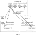
- FIG. 1 is a schematic architecture diagram of a specific implementation of a high-throughput computer data center in the prior art.
- a computer device includes a central processing unit, a memory, and a cloud controller.
- the cloud controller is connected to a remote resource pool by using a network.
- the remote resource pool includes storage resources, input/output resources, or the like.
- the storage resources for example, a dynamic random access memory (DRAM, Dynamic Random Access Memory) and a non-volatile memory (NVM, Non-Volatile Memory), form a storage resource pool.
- the input/output resources for example, a network adapter and a Peripheral Component Interconnect Express PCIe interface, form an input/output resource pool. It should be noted that FIG.
- FIG. 1 shows merely an example of a structural diagram of a high-throughput computer data center.
- another hardware resource for example, a bus
- another resource pool for example, a computing resource pool
- multiple central processing units and multiple memories may form a computing resource pool or the like.
- a quantity of resources in the resource pool shown in FIG. 1 is used as an example.
- at least two resources may be included, for example, a memory resource pool may include at least two memories.
- a CPU in the computer device in addition to a local memory (for example, a dynamic random access memory DRAM using a DDR interface), a CPU in the computer device also has a remote storage space allocated by a system. Each physical storage space is mapped to a global address space. A mapping relationship of the address space is stored in a driver of a cloud controller corresponding to each CPU. For example, a CPU 1 has a 10 GB local memory and a 100 GB remote storage resource (that is, storage spaces in the storage resource pool that are connected by using a network and can be accessed) in total.
- the CPU 1 can access a remote storage resource pool including a storage space A and a storage space B, and the storage space A and the storage space B each are a storage resource with a capacity of 50 GB, the CPU 1 can access a 110 GB storage space in total: a storage space of 0 to 10 GB in the local memory and a storage space of 10 GB to 110 GB in the remote storage resource pool.
- a cloud controller 1 can read the data only by accessing the remote storage resource pool by using a network. Because network transmission is required, the cloud controller 1 cannot return the required data to the CPU 1 at a DDR interface within a specified time. Therefore, after receiving a data read request delivered by the CPU 1, the cloud controller 1 packs the request, sends the request to the storage resource pool by using the network, to obtain data, and returns an ECC error or a PAGE error to the CPU 1.
- the CPU 1 When receiving error information sent by the cloud controller 1, the CPU 1 interrupts current memory access and suspends a corresponding access thread. After receiving the data sent from the storage resource pool, the cloud controller 1 generates an interrupt signal to notify the CPU 1. The CPU 1 can obtain, according to the received interrupt signal and only by resending a memory reading request, the data that needs to be read. Because the data has been written into a storage space of the cloud controller 1 at this time, the CPU 1 can obtain the data at the DDR interface within a specified time. Therefore, when data that needs to be accessed by the CPU 1 is not inside the cloud controller 1, the CPU 1 needs to perform one interrupt operation and two read operations. As a result, a high access delay is caused, and overall performance of a system is affected because the CPU 1 cannot perform another operation during the interruption.
- an embodiment of the present invention provides a computer device 10.
- the computer device 10 includes a central processing unit CPU 100 and a cloud controller 200.
- the cloud controller 200 includes a transmission queue module 201, a response queue module 202, a double data rate DDR interface 203, and a network interface 204.
- the DDR interface 203 is configured to connect the CPU 100 to the cloud controller 200
- the network interface 204 is configured to connect the cloud controller 200 to a network device.
- the CPU 100 is configured to: after generating a request for performing a read/write operation on the network device, convert the read/write operation request into a control command, and write the control command into the transmission queue module 201.
- the control command is used to instruct the cloud controller 200 to perform a read operation or a write operation on the network device, and the control command carries operation information of the read operation or the write operation.
- the cloud controller 200 is configured to: when the control command in the transmission queue module 201 is triggered, perform the read operation or the write operation on the network device according to the operation information in the control command, receive a response message sent by the network device, and write the response message sent by the network device into the response queue module 202.
- the network device connected to the computer device 10 by using the network interface 204 is a device connected to the computer device 10 by using a network.
- the cloud controller 200 needs to send a data read/write message to the network device by using the network, and receives a response message or data returned by the network device by using the network.
- the CPU 100 is connected to the cloud controller 200 by using the DDR interface 203, and an interrupt is avoided because the DDR interface 203 has a high data transmission rate.
- the CPU 100 converts a read/write operation request into a control command and writes the control command into the transmission queue module 201 of the cloud controller 200.
- the cloud controller 200 performs the read operation or the write operation on the network device according to operation information in the control command, after writing the control command into the transmission queue module 201, the CPU 100 does not need to wait for an operation performed by the cloud controller 200, and can continue to perform other service processing, for example, continue to write another control command. This avoids a waste of CPU 100 resources, and improves CPU 100 utilization and overall performance of the computer device.
- the transmission queue module 201 and the response queue module 202 of the cloud controller 200 may be implemented by hardware such as a register or a memory, and are connected to the DDR interface and the like by using a hardware interface.
- the transmission queue module 201 stores, by using hardware such as a register, a control command written by the CPU 100
- the response queue module 202 stores a response message by using hardware such as a register.
- the transmission queue module 201 and the response queue module 202 store related commands or messages in an ordered arrangement manner such as in a queue form, so that the cloud controller 200 can read commands or write response messages in a queue form.
- control command in the transmission queue module 201 is triggered may be that when the control command is written into the transmission queue module 201, the cloud controller 200 is triggered to extract the control command from the transmission queue module 201 and execute the control command.
- a control unit or a control module of the cloud controller 200 may extract the control command from the transmission queue module 201 and execute the control command.
- the control unit or the control module of the cloud controller 200 is also a hardware control component, and is connected to the transmission queue module 201, the response queue module 202, or the network interface 204 by using an interface.
- the converting the read operation request into a read control command, and writing the read control command into the command transmission queue module 2011 is implemented by a driver that runs in the CPU 100.
- That the read control command in the command transmission queue module 2011 is triggered may be that when the read control command is written into the command transmission queue module 2011, the cloud controller is triggered to extract the read control command from the command transmission queue module 2011.
- a control unit or a control module of the cloud controller may extract the read control command from the command transmission queue module 2011 when the read control command is written into the command transmission queue module 2011, and execute the read control command.
- the read operation information may include an address, in the network device, of the data to be read by means of the read operation and a length of the data to be read by means of the read operation; or the read operation information includes a node address and an offset address, in the network device, of the data to be read by means of the read operation and a length of the data to be read by means of the read operation.
- the performing, by the cloud controller 200, the read operation on the network device according to the read operation information in the read control command may include: creating a communications packet by using the address, in the network device, of the data to be read by means of the read operation and the length of the data to be read by means of the read operation, and sending the communications packet to the network device by using a network; or creating, by the cloud controller 200, a communications packet by using the node address and the offset address, in the network device, of the data to be read by means of the read operation and the length of the data to be read by means of the read operation, and sending the communications packet to the network device by using a network.
- the communications packet may be a PRAP data packet.
- the CPU 100 may perform another operation, for example, continue to write another read control command or write control command.
- the cloud controller 200 may extract the read control command from the command transmission queue module 2011 when the read control command is written into the command transmission queue module 2011, execute the read control command, write a result of executing the read control command into the response command queue module 2021, and when obtaining data that is read, write the read data into the data receiving queue module 2022. In this way, a read operation request is converted into two processes of writing a read control command by the CPU 100 and executing the read control command by the cloud controller 200.
- the CPU 100 can execute another task with no need to wait for a result of performing a read operation by the cloud controller 200, and only needs to obtain a read operation result when a read operation response command is written into the response command queue module 2021. This avoids an interrupt caused because the CPU 100 waits for a read operation result for an excessively long time, and improves resource utilization of the CPU 100 and overall performance of a system.
- the CPU 100 may obtain the read operation result by querying in a polling manner or by being notified by means of an interrupt. For example, after writing the read control command into the command transmission queue module, the CPU 100 queries, in a polling manner, whether the read response message sent by the network device exists in the response command queue module 2021, that is, repeatedly queries, according to a preset time interval, whether the read response message sent by the network device exists in the response command queue module 2021. When determining that the read response message sent by the network device exists in the response command queue module 2021, the CPU 100 obtains the response message in the response command queue module 2021. When the read response message is a read success response message, the CPU 100 reads, from the data receiving queue module 2022, the data to be read by means of the read operation.
- the obtaining the read operation result by being notified by means of an interrupt includes: determining, by the cloud controller 200, whether the read response message sent by the network device exists in the response command queue module 2021, and notifying the CPU 100 by means of an interrupt when the read response message sent by the network device exists in the response command queue module 2021.
- the response command queue module 2021 may notify the CPU 100 by means of an interrupt when the read response message is written into the response command queue module 2021.
- the CPU 100 receives an interrupt message sent by the cloud controller 200, obtains the read response message from the response command queue module 2021 according to the interrupt message, and when the obtained read response message indicates a read success, reads, from the data receiving queue module 2022, the data to be read by means of the read operation.
- the CPU 100 may write a polling-based query manner or an interrupt-based notification manner into a register of the cloud controller 200.
- the cloud controller 200 obtains, from the register, information written by the CPU 100.
- the CPU 100 proactively queries, in a polling manner, the response command queue module 2021; if the interrupt-based notification manner is written into the register, the cloud controller 200 notifies the CPU 100 by means of an interrupt when the read response message is written into the response command queue module 2021.
- the converting the write operation request into a write control command and writing the write control command into the command transmission queue module 2011 is implemented by a driver that runs in the CPU 100.
- That the write control command in the command transmission queue module 2011 is triggered may be that when the write control command is written into the command transmission queue module 2011, the cloud controller is triggered to extract the write control command from the command transmission queue module 2011.
- a control unit or a control module of the cloud controller may extract the write control command from the command transmission queue module 2011 when the write control command is written into the command transmission queue module 2011, and execute the read control command.
- the write operation information includes an address of the network device, a length of the data to be written by means of the write operation, and an address, in the data transmission queue module, of the data to be written by means of the write operation; or the write operation information includes a node address and an offset address of the network device, a length of the data to be written by means of the write operation, and an address, in the data transmission queue module, of the data to be written by means of the write operation.
- the extracting, by the cloud controller 200 from the data transmission queue module 2012 according to the write operation information in the write control command, the data to be written by means of the write operation, and writing, into the network device, the data to be written by means of the write operation may include: creating a communications packet by using the data to be written by means of the write operation, the address of the network device, and the length of the data to be written by means of the write operation, and sending the communications packet to the network device by using a network; or creating, by the cloud controller 200, a communications packet by using the data to be written by means of the write operation, the node address and the offset address of the network device, and the length of the data to be written by means of the write operation, and sending the communications packet to the network device by using a network.
- the communications packet may be a PRAP data packet.
- the CPU 100 may perform another operation, for example, continue to write another read control command or write control command.
- the cloud controller 200 may extract the write control command from the command transmission queue module 2011 when the write control command is written into the command transmission queue module 2011, execute the write control command, and write a result of executing the write control command into the response command queue module 2021. In this way, a write operation request is converted into two processes of writing a write control command into the command transmission queue module 2011 of the cloud controller and executing the write control command by the cloud controller 200.
- the CPU 100 can execute another task with no need to wait for a result of performing a write operation by the cloud controller 200, and only needs to obtain a write operation result when a write operation response command is written into the response command queue module 2021. This avoids an interrupt caused because the CPU 100 waits for a write operation result for an excessively long time, and improves resource utilization of the CPU 100 and overall performance of the computer device.
- the CPU 100 may further obtain the write operation result by querying in a polling manner or by being notified by means of an interrupt. For example, after writing the write control command into the command transmission queue module, the CPU 100 queries, in a polling manner, whether the write response message sent by the network device exists in the response command queue module 2021, that is, repeatedly queries, according to a preset time interval, whether the write response message sent by the network device exists in the response command queue module 2021. When determining that the write response message sent by the network device exists in the response command queue module 2021, the CPU 100 obtains the write response message.
- the obtaining the write operation result by being notified by means of an interrupt includes: determining, by the cloud controller 200, whether the write response message sent by the network device exists in the response command queue module 2021, and notifying the CPU 100 by means of an interrupt when the write response message sent by the network device exists in the response command queue module 2021.
- the cloud controller 200 may notify the CPU 100 by means of an interrupt when the write response message is written into the response command queue module 2021.
- the CPU 100 is further configured to: receive an interrupt message sent by the cloud controller 200, and obtain the write response message from the response command queue module 2021 according to the interrupt message.
- the command transmission queue module 2011, the data transmission queue module 2012, the response command queue module 2021, and the data receiving queue module 2022 may be implemented by hardware such as a register or a memory, and are connected to the DDR interface or the like by using a hardware interface.
- the command transmission queue module 2011 and the response command queue module 2021 store related commands or messages in an ordered arrangement manner such as in a queue form
- the data transmission queue module 2012 and the data receiving queue module 2022 store related data in an ordered arrangement manner such as in a queue form, so that the cloud controller 200 can perform reading or writing in a queue form.
- a control unit or a control module of the cloud controller 200 may extract a control command from the command transmission queue module 2011 or the response command queue module 2021, execute the control command, and read data from the data transmission queue module 2012 or write data into the data receiving queue module 2022.
- the control unit or the control module of the cloud controller 200 is also a hardware control component, and is connected to the command transmission queue module 2011, the data transmission queue module 2012, the response command queue module 2021, the data receiving queue module 2022, and the network interface 204 by using interfaces.
- the computer device 10 further includes a memory, and the CPU 100 obtains to-be-read data from the data receiving queue module 2022 and writes the to-be-read data into the memory.
- the to-be-read data may be written into the memory in a direct memory access (DMA, Direct Memory Access) manner.
- DMA Direct Memory Access
- the writing, by the CPU 100 into the data transmission queue module 2012, the data to be written by means of the write operation is writing, into the data transmission queue module 2012 by configuring a DMA controller of a memory controller (MC, Memory Controller), the data in the memory that is to be written by means of the write operation.
- MC Memory Controller
- the network device is a device connected to the computer device by using a network, and includes a device that provides a storage resource or a device that provides an input/output resource.
- the device that provides a storage resource includes a device that provides a memory resource.
- the computer device 10 in the foregoing embodiment may be applied to a high-throughput computer data center, and is used as a high-throughput computer for data processing.
- the computer device 10 may include at least two CPUs and at least two memories. The at least two CPUs form a CPU resource pool and separately process data in the high-throughput computer data center.
- the DDR interface in the foregoing embodiment is a quick interface for reading/writing data between a CPU and a memory currently.
- the DDR is used between the CPU 100 and the cloud controller 200, so as to meet a requirement of quickly obtaining data by the CPU.
- no limitation is imposed on a specific form of an interface used between a CPU and a cloud controller.
- Another interface that can be used for quickly reading/writing data and that can meet a requirement of quickly reading/writing data by a CPU for example, an interface whose reading/writing rate is equal to or similar to a reading/writing rate between a CPU and a memory, can be used as an interface between the CPU and the cloud controller.
- a CPU 1 in a CPU resource pool in addition to a local memory (for example, a DRAM using a DDR interface), a CPU 1 in a CPU resource pool also has remote storage spaces (a storage space A and a storage space B) allocated by a system. Each physical storage space is mapped to a global address space. A mapping relationship of the address space is stored in a driver of a cloud controller corresponding to each CPU.
- the remote storage spaces include only the storage space A and the storage space B.
- two or more storage spaces may be included.
- the CPU 1 has a 10 GB local memory and a 100 GB remote storage resource in total, the CPU 1 can access a remote storage resource pool including the storage space A and the storage space B, and the storage space A and the storage space B each are a storage space with a capacity of 50 GB.
- the CPU 1 can access a 110 GB storage space in total: a storage space of 0 to 10 GB in the local memory and a storage space of 10 GB to 110 GB in the remote storage resource pool.
- the CPU 1 accesses the local memory, if an address space of 0 GB to 10 GB is accessed, the address space is mapped to the local memory, and the local memory is accessed by using the DDR interface.
- the specific implementation is described by using a network device for storing a resource as an example.
- the computer device provided in this embodiment of the present invention may read data from a device that provides an input/output resource or write data into a device that provides an input/output resource.
- the network device is the device that provides the input/output resource.
- An embodiment of the present invention further provides a method for reading/writing data by a computer device.
- the computer device includes a central processing unit CPU, a cloud controller, and a network interface.
- the CPU is connected to the cloud controller by using a double data rate DDR interface, and the network interface is configured to connect the cloud controller to a network device.
- FIG. 5 is a schematic flowchart of a method for reading/writing data by a computer device according to an embodiment of the present invention. The method includes the following steps:
- the CPU is connected to the cloud controller by using the DDR interface, and an interrupt is avoided because the DDR interface has a high data transmission rate.
- the CPU converts a read/write operation request into a control command and writes the control command into the transmission queue module of the cloud controller. Because the cloud controller performs the read operation or the write operation on the network device according to operation information in the control command, after writing the control command into the transmission queue module, the CPU does not need to wait for an operation performed by the cloud controller and can continue to perform other service processing, for example, continue to write another control command. This avoids a waste of CPU resources, and improves CPU utilization.
- the converting, by the CPU, a request for performing a read/write operation on the network device into a control command, and writing the control command into a transmission queue module of the cloud controller includes:
- the read operation information may include an address, in the network device, of the data to be read by means of the read operation and a length of the data to be read by means of the read operation; or the read operation information includes a node address and an offset address, in the network device, of the data to be read by means of the read operation and a length of the data to be read by means of the read operation.
- the CPU may perform another operation, for example, continue to write another read control command or write control command.
- the cloud controller may extract the read control command from the command transmission queue module when the read control command is written into the command transmission queue module, execute the read control command, write a result of executing the read control command into the response command queue module, and write read data into the data receiving queue module when obtaining the read data. In this way, a read operation request is converted into two processes of writing a read control command by a CPU and executing the read control command by the cloud controller.
- the CPU can execute another task with no need to wait for a result of performing a read operation by the cloud controller, and only needs to obtain a read operation result when a read operation response command is written into the response command queue module. This avoids an interrupt caused because the CPU waits for a read operation result for an excessively long time, and improves resource utilization of the CPU.
- the CPU may obtain the read operation result by querying in a polling manner or by being notified by means of an interrupt.
- the CPU queries, in a polling manner, after writing the read control command into the command transmission queue module, whether the read response message sent by the network device exists in the response command queue module, that is, repeatedly queries, according to a preset time interval, whether the read response message sent by the network device exists in the response command queue module.
- the CPU reads, from the data receiving queue module, data to be read by means of the read operation.
- the cloud controller determines whether the read response message sent by the network device exists in the response command queue module, and notifies the CPU by means of an interrupt when the read response message sent by the network device exists in the response command queue module.
- the CPU receives an interrupt message sent by the cloud controller, obtains the read response message from the response command queue module according to the interrupt message, and when the obtained read response message indicates a read success, reads, from the data receiving queue module, the data to be read by means of the read operation.
- the converting, by the CPU, a request for performing a read/write operation on the network device into a control command, and writing the control command into a transmission queue module of the cloud controller includes:
- the write operation information may include an address of the network device, a length of the data to be written by means of the write operation, and an address, in the data transmission queue module, of the data to be written by means of the write operation; or the write operation information includes a node address and an offset address of the network device, a length of the data to be written by means of the write operation, and an address, in the data transmission queue module, of the data to be written by means of the write operation.
- the cloud controller may extract the write control command from the command transmission queue module when the write control command is written into the command transmission queue module, execute the write control command, and write a result of executing the write control command into the response command queue module.
- a write operation request is converted into two processes of writing a write control command into the command transmission queue module of the cloud controller and executing the write control command by the cloud controller.
- the CPU can execute another task with no need to wait for a result of performing a write operation by the cloud controller, and only needs to obtain a write operation result when a write operation response command is written into the response command queue module. This avoids an interrupt caused because the CPU waits for a write operation result for an excessively long time, and improves resource utilization of the CPU.
- the CPU may obtain the write operation result by querying in a polling manner or by being notified by means of an interrupt.
- the CPU queries, in a polling manner, after writing the write control command into the command transmission queue module, whether the write response message sent by the network device exists in the response command queue module, and the CPU obtains the write response message when determining that the write response message sent by the network device exists in the response command queue module.
- the cloud controller determines whether the write response message sent by the network device exists in the response command queue module, and notifies the CPU by means of an interrupt when the write response message sent by the network device exists in the response command queue module.
- the CPU receives an interrupt message sent by the cloud controller, and obtains the write response message from the response command queue module according to the interrupt message.
- the disclosed system, apparatus, and method may be implemented in other manners.
- the described apparatus embodiment is merely an example.
- the unit division is merely logical function division and may be other division in actual implementation.
- a plurality of units or components may be combined or integrated into another system, or some features may be ignored or not performed.
- the displayed or discussed mutual couplings or direct couplings or communication connections may be implemented through some interfaces, indirect couplings or communication connections between the apparatuses or units, or electrical connections, mechanical connections, or connections in other forms.
- the units described as separate parts may or may not be physically separate, and parts displayed as units may or may not be physical units, may be located in one position, or may be distributed on a plurality of network units. A part or all of the units may be selected according to actual needs to achieve the objectives of the solutions of the embodiments of the present invention.
- functional units in the embodiments of the present invention may be integrated into one processing unit, or each of the units may exist alone physically, or two or more units are integrated into one unit.
- the integrated unit may be implemented in a form of hardware, or may be implemented in a form of a software functional unit.
- the integrated unit When the integrated unit is implemented in the form of a software functional unit and sold or used as an independent product, the integrated unit may be stored in a computer-readable storage medium. Based on such an understanding, the technical solutions of the present invention essentially, or the part contributing to the prior art, or all or a part of the technical solutions may be implemented in the form of a software product.
- the software product is stored in a storage medium and includes several instructions for instructing a computer device (which may be a personal computer, a server, or a network device) to perform all or a part of the steps of the methods described in the embodiments of the present invention.
- the foregoing storage medium includes: any medium that can store program code, such as a USB flash drive, a removable hard disk, a read-only memory (ROM, Read-Only Memory), a random access memory (RAM, Random Access Memory), a magnetic disk, or an optical disc.
- program code such as a USB flash drive, a removable hard disk, a read-only memory (ROM, Read-Only Memory), a random access memory (RAM, Random Access Memory), a magnetic disk, or an optical disc.
Landscapes
- Engineering & Computer Science (AREA)
- Theoretical Computer Science (AREA)
- Physics & Mathematics (AREA)
- General Engineering & Computer Science (AREA)
- General Physics & Mathematics (AREA)
- Human Computer Interaction (AREA)
- Computer Security & Cryptography (AREA)
- Computer Networks & Wireless Communication (AREA)
- Signal Processing (AREA)
- Computer And Data Communications (AREA)
Applications Claiming Priority (1)
| Application Number | Priority Date | Filing Date | Title |
|---|---|---|---|
| PCT/CN2015/084816 WO2017012096A1 (zh) | 2015-07-22 | 2015-07-22 | 计算机设备和计算机设备数据读写的方法 |
Publications (3)
| Publication Number | Publication Date |
|---|---|
| EP3296836A1 EP3296836A1 (en) | 2018-03-21 |
| EP3296836A4 EP3296836A4 (en) | 2018-06-20 |
| EP3296836B1 true EP3296836B1 (en) | 2019-09-11 |
Family
ID=57833686
Family Applications (1)
| Application Number | Title | Priority Date | Filing Date |
|---|---|---|---|
| EP15898652.1A Active EP3296836B1 (en) | 2015-07-22 | 2015-07-22 | Computer device and data read-write method for computer device |
Country Status (9)
| Country | Link |
|---|---|
| US (1) | US10951741B2 (zh) |
| EP (1) | EP3296836B1 (zh) |
| JP (1) | JP6498844B2 (zh) |
| CN (1) | CN106662895B (zh) |
| AU (1) | AU2015402888B2 (zh) |
| CA (1) | CA2987807C (zh) |
| ES (1) | ES2757673T3 (zh) |
| SG (1) | SG11201709668SA (zh) |
| WO (1) | WO2017012096A1 (zh) |
Families Citing this family (6)
| Publication number | Priority date | Publication date | Assignee | Title |
|---|---|---|---|---|
| US10552271B2 (en) * | 2017-07-31 | 2020-02-04 | International Business Machines Corporation | Switching servers without interrupting a client command-response queue |
| KR20210045073A (ko) | 2019-10-16 | 2021-04-26 | 휴렛-팩커드 디벨롭먼트 컴퍼니, 엘.피. | 효율적인 메모리 배치 |
| CN111061430B (zh) * | 2019-11-27 | 2021-02-19 | 东南大学 | 一种多云环境下异构i/o细粒度感知的数据放置方法 |
| CN111858447A (zh) * | 2020-07-13 | 2020-10-30 | 深圳市集贤科技有限公司 | 一种从串口接收数据、处理数据帧的方法 |
| CN112925481B (zh) | 2021-03-09 | 2024-04-05 | 合肥兆芯电子有限公司 | 存储器管理方法、存储器存储装置及存储器控制电路单元 |
| CN114296640B (zh) * | 2021-12-13 | 2023-08-15 | 苏州浪潮智能科技有限公司 | 用于加速计算的数据驱动方法、装置、设备和存储介质 |
Family Cites Families (24)
| Publication number | Priority date | Publication date | Assignee | Title |
|---|---|---|---|---|
| US7010575B1 (en) | 2000-03-31 | 2006-03-07 | Emc Corporation | Data storage system having separate data transfer section and message network having bus arbitration |
| GB0221464D0 (en) | 2002-09-16 | 2002-10-23 | Cambridge Internetworking Ltd | Network interface and protocol |
| JP2004220216A (ja) * | 2003-01-14 | 2004-08-05 | Hitachi Ltd | San/nas統合型ストレージ装置 |
| JP4536361B2 (ja) * | 2003-11-28 | 2010-09-01 | 株式会社日立製作所 | データ転送装置、記憶デバイス制御装置、記憶デバイス制御装置の制御方法 |
| JP2007027951A (ja) * | 2005-07-13 | 2007-02-01 | Matsushita Electric Ind Co Ltd | Dmaコントローラおよび通信処理装置 |
| JP2008226040A (ja) * | 2007-03-14 | 2008-09-25 | Hitachi Ltd | 情報処理装置及びコマンド多重度制御方法 |
| JP5112138B2 (ja) * | 2008-03-28 | 2013-01-09 | 株式会社日立製作所 | セッション管理方法、ストレージ装置、及び、計算機システム |
| US8832130B2 (en) * | 2010-08-19 | 2014-09-09 | Infosys Limited | System and method for implementing on demand cloud database |
| US8589625B2 (en) * | 2010-09-15 | 2013-11-19 | Pure Storage, Inc. | Scheduling of reconstructive I/O read operations in a storage environment |
| US8751714B2 (en) | 2010-09-24 | 2014-06-10 | Intel Corporation | Implementing quickpath interconnect protocol over a PCIe interface |
| CN202178776U (zh) * | 2011-08-23 | 2012-03-28 | 杭州朗杰测控技术开发有限公司 | 一种基于can总线的高速通讯系统 |
| US10445121B2 (en) | 2012-02-23 | 2019-10-15 | Red Hat Inc. | Building virtual machine disk images for different cloud configurations from a single generic virtual machine disk image |
| WO2014029076A1 (en) * | 2012-08-21 | 2014-02-27 | Intel Corporation | Widi cloud mode |
| US9286130B2 (en) * | 2012-08-27 | 2016-03-15 | International Business Machines Corporation | Optimizing virtual machine deployment time by temporarily allocating more processing resources during the initial deployment time of the virtual machine |
| US8831000B2 (en) * | 2012-10-10 | 2014-09-09 | Telefonaktiebolaget L M Ericsson (Publ) | IP multicast service join process for MPLS-based virtual private cloud networking |
| US9712402B2 (en) * | 2012-10-10 | 2017-07-18 | Alcatel Lucent | Method and apparatus for automated deployment of geographically distributed applications within a cloud |
| US9344521B2 (en) * | 2012-12-13 | 2016-05-17 | Red Hat, Inc. | Pluggable infrastructure for cloud provider selection |
| US20140172783A1 (en) * | 2012-12-17 | 2014-06-19 | Prowess Consulting, Llc | System and method for providing computing environment delivery service with offline operations |
| US9256384B2 (en) | 2013-02-04 | 2016-02-09 | Avago Technologies General Ip (Singapore) Pte. Ltd. | Method and system for reducing write latency in a data storage system by using a command-push model |
| US9087007B2 (en) * | 2013-03-14 | 2015-07-21 | International Business Machines Corporation | Generating fault tolerant connectivity API |
| US8769644B1 (en) * | 2013-03-15 | 2014-07-01 | Rightscale, Inc. | Systems and methods for establishing cloud-based instances with independent permissions |
| CN103414764A (zh) * | 2013-07-24 | 2013-11-27 | 广东电子工业研究院有限公司 | 一种云平台弹性存储系统及其弹性存储实现方法 |
| US9880971B2 (en) * | 2013-12-20 | 2018-01-30 | Rambus Inc. | Memory appliance for accessing memory |
| US8874836B1 (en) * | 2014-07-03 | 2014-10-28 | Pure Storage, Inc. | Scheduling policy for queues in a non-volatile solid-state storage |
-
2015
- 2015-07-22 CA CA2987807A patent/CA2987807C/en active Active
- 2015-07-22 AU AU2015402888A patent/AU2015402888B2/en active Active
- 2015-07-22 WO PCT/CN2015/084816 patent/WO2017012096A1/zh active Application Filing
- 2015-07-22 ES ES15898652T patent/ES2757673T3/es active Active
- 2015-07-22 SG SG11201709668SA patent/SG11201709668SA/en unknown
- 2015-07-22 EP EP15898652.1A patent/EP3296836B1/en active Active
- 2015-07-22 JP JP2018518763A patent/JP6498844B2/ja active Active
- 2015-07-22 CN CN201580002875.8A patent/CN106662895B/zh active Active
-
2018
- 2018-01-18 US US15/874,852 patent/US10951741B2/en active Active
Non-Patent Citations (1)
| Title |
|---|
| None * |
Also Published As
| Publication number | Publication date |
|---|---|
| EP3296836A4 (en) | 2018-06-20 |
| CA2987807A1 (en) | 2017-01-26 |
| WO2017012096A1 (zh) | 2017-01-26 |
| JP2018524751A (ja) | 2018-08-30 |
| CN106662895B (zh) | 2019-10-18 |
| AU2015402888A1 (en) | 2017-12-21 |
| SG11201709668SA (en) | 2017-12-28 |
| US10951741B2 (en) | 2021-03-16 |
| JP6498844B2 (ja) | 2019-04-10 |
| US20180159963A1 (en) | 2018-06-07 |
| AU2015402888B2 (en) | 2018-09-27 |
| CN106662895A (zh) | 2017-05-10 |
| ES2757673T3 (es) | 2020-04-29 |
| CA2987807C (en) | 2019-12-31 |
| EP3296836A1 (en) | 2018-03-21 |
Similar Documents
| Publication | Publication Date | Title |
|---|---|---|
| US10951741B2 (en) | Computer device and method for reading or writing data by computer device | |
| US10997093B2 (en) | NVME data processing method and NVME device | |
| US11929927B2 (en) | Network interface for data transport in heterogeneous computing environments | |
| CN109471833B (zh) | 用于最大化PCIe对等连接的带宽的系统和方法 | |
| EP2849076B1 (en) | Dma transmission method and system | |
| US9395921B2 (en) | Writing data using DMA by specifying a buffer address and a flash memory address | |
| US9467512B2 (en) | Techniques for remote client access to a storage medium coupled with a server | |
| EP3470971B1 (en) | Method, apparatus, and system for accessing memory device | |
| KR20150132432A (ko) | 네트워크를 통한 메모리 공유 | |
| US20220222016A1 (en) | Method for accessing solid state disk and storage device | |
| WO2016000470A1 (zh) | 一种内存控制方法和装置 | |
| US20170185546A1 (en) | Remote Resource Access Method and Switching Device | |
| US9146693B2 (en) | Storage control device, storage system, and storage control method | |
| US10733118B2 (en) | Computer system, communication device, and storage control method with DMA transfer of data | |
| WO2023186143A1 (zh) | 一种数据处理方法、主机及相关设备 | |
| US10853255B2 (en) | Apparatus and method of optimizing memory transactions to persistent memory using an architectural data mover | |
| CN112463027B (zh) | 一种i/o处理方法、系统、设备及计算机可读存储介质 | |
| US20240168876A1 (en) | Solving submission queue entry overflow using metadata or data pointers | |
| WO2022141250A1 (zh) | 数据传输方法和相关装置 |
Legal Events
| Date | Code | Title | Description |
|---|---|---|---|
| STAA | Information on the status of an ep patent application or granted ep patent |
Free format text: STATUS: THE INTERNATIONAL PUBLICATION HAS BEEN MADE |
|
| PUAI | Public reference made under article 153(3) epc to a published international application that has entered the european phase |
Free format text: ORIGINAL CODE: 0009012 |
|
| STAA | Information on the status of an ep patent application or granted ep patent |
Free format text: STATUS: REQUEST FOR EXAMINATION WAS MADE |
|
| 17P | Request for examination filed |
Effective date: 20171214 |
|
| AK | Designated contracting states |
Kind code of ref document: A1 Designated state(s): AL AT BE BG CH CY CZ DE DK EE ES FI FR GB GR HR HU IE IS IT LI LT LU LV MC MK MT NL NO PL PT RO RS SE SI SK SM TR |
|
| AX | Request for extension of the european patent |
Extension state: BA ME |
|
| A4 | Supplementary search report drawn up and despatched |
Effective date: 20180523 |
|
| RIC1 | Information provided on ipc code assigned before grant |
Ipc: G06F 1/16 20060101AFI20180516BHEP Ipc: G06F 3/06 20060101ALI20180516BHEP |
|
| DAV | Request for validation of the european patent (deleted) | ||
| DAX | Request for extension of the european patent (deleted) | ||
| REG | Reference to a national code |
Ref country code: DE Ref legal event code: R079 Ref document number: 602015038060 Country of ref document: DE Free format text: PREVIOUS MAIN CLASS: G06F0001160000 Ipc: G06F0003060000 |
|
| GRAP | Despatch of communication of intention to grant a patent |
Free format text: ORIGINAL CODE: EPIDOSNIGR1 |
|
| STAA | Information on the status of an ep patent application or granted ep patent |
Free format text: STATUS: GRANT OF PATENT IS INTENDED |
|
| RIC1 | Information provided on ipc code assigned before grant |
Ipc: H04L 29/06 20060101ALN20190130BHEP Ipc: G06F 1/16 20060101ALI20190130BHEP Ipc: G06F 3/06 20060101AFI20190130BHEP Ipc: G06F 13/32 20060101ALN20190130BHEP |
|
| RIC1 | Information provided on ipc code assigned before grant |
Ipc: H04L 29/06 20060101ALN20190211BHEP Ipc: G06F 3/06 20060101AFI20190211BHEP Ipc: G06F 1/16 20060101ALI20190211BHEP Ipc: G06F 13/32 20060101ALN20190211BHEP |
|
| INTG | Intention to grant announced |
Effective date: 20190301 |
|
| GRAS | Grant fee paid |
Free format text: ORIGINAL CODE: EPIDOSNIGR3 |
|
| GRAA | (expected) grant |
Free format text: ORIGINAL CODE: 0009210 |
|
| STAA | Information on the status of an ep patent application or granted ep patent |
Free format text: STATUS: THE PATENT HAS BEEN GRANTED |
|
| AK | Designated contracting states |
Kind code of ref document: B1 Designated state(s): AL AT BE BG CH CY CZ DE DK EE ES FI FR GB GR HR HU IE IS IT LI LT LU LV MC MK MT NL NO PL PT RO RS SE SI SK SM TR |
|
| REG | Reference to a national code |
Ref country code: GB Ref legal event code: FG4D |
|
| REG | Reference to a national code |
Ref country code: CH Ref legal event code: EP |
|
| REG | Reference to a national code |
Ref country code: AT Ref legal event code: REF Ref document number: 1179326 Country of ref document: AT Kind code of ref document: T Effective date: 20190915 |
|
| REG | Reference to a national code |
Ref country code: DE Ref legal event code: R096 Ref document number: 602015038060 Country of ref document: DE Ref country code: IE Ref legal event code: FG4D |
|
| REG | Reference to a national code |
Ref country code: NL Ref legal event code: FP |
|
| REG | Reference to a national code |
Ref country code: LT Ref legal event code: MG4D |
|
| PG25 | Lapsed in a contracting state [announced via postgrant information from national office to epo] |
Ref country code: FI Free format text: LAPSE BECAUSE OF FAILURE TO SUBMIT A TRANSLATION OF THE DESCRIPTION OR TO PAY THE FEE WITHIN THE PRESCRIBED TIME-LIMIT Effective date: 20190911 Ref country code: BG Free format text: LAPSE BECAUSE OF FAILURE TO SUBMIT A TRANSLATION OF THE DESCRIPTION OR TO PAY THE FEE WITHIN THE PRESCRIBED TIME-LIMIT Effective date: 20191211 Ref country code: NO Free format text: LAPSE BECAUSE OF FAILURE TO SUBMIT A TRANSLATION OF THE DESCRIPTION OR TO PAY THE FEE WITHIN THE PRESCRIBED TIME-LIMIT Effective date: 20191211 Ref country code: SE Free format text: LAPSE BECAUSE OF FAILURE TO SUBMIT A TRANSLATION OF THE DESCRIPTION OR TO PAY THE FEE WITHIN THE PRESCRIBED TIME-LIMIT Effective date: 20190911 Ref country code: LT Free format text: LAPSE BECAUSE OF FAILURE TO SUBMIT A TRANSLATION OF THE DESCRIPTION OR TO PAY THE FEE WITHIN THE PRESCRIBED TIME-LIMIT Effective date: 20190911 Ref country code: HR Free format text: LAPSE BECAUSE OF FAILURE TO SUBMIT A TRANSLATION OF THE DESCRIPTION OR TO PAY THE FEE WITHIN THE PRESCRIBED TIME-LIMIT Effective date: 20190911 |
|
| PG25 | Lapsed in a contracting state [announced via postgrant information from national office to epo] |
Ref country code: GR Free format text: LAPSE BECAUSE OF FAILURE TO SUBMIT A TRANSLATION OF THE DESCRIPTION OR TO PAY THE FEE WITHIN THE PRESCRIBED TIME-LIMIT Effective date: 20191212 Ref country code: RS Free format text: LAPSE BECAUSE OF FAILURE TO SUBMIT A TRANSLATION OF THE DESCRIPTION OR TO PAY THE FEE WITHIN THE PRESCRIBED TIME-LIMIT Effective date: 20190911 Ref country code: AL Free format text: LAPSE BECAUSE OF FAILURE TO SUBMIT A TRANSLATION OF THE DESCRIPTION OR TO PAY THE FEE WITHIN THE PRESCRIBED TIME-LIMIT Effective date: 20190911 Ref country code: LV Free format text: LAPSE BECAUSE OF FAILURE TO SUBMIT A TRANSLATION OF THE DESCRIPTION OR TO PAY THE FEE WITHIN THE PRESCRIBED TIME-LIMIT Effective date: 20190911 |
|
| REG | Reference to a national code |
Ref country code: AT Ref legal event code: MK05 Ref document number: 1179326 Country of ref document: AT Kind code of ref document: T Effective date: 20190911 |
|
| REG | Reference to a national code |
Ref country code: ES Ref legal event code: FG2A Ref document number: 2757673 Country of ref document: ES Kind code of ref document: T3 Effective date: 20200429 |
|
| PG25 | Lapsed in a contracting state [announced via postgrant information from national office to epo] |
Ref country code: EE Free format text: LAPSE BECAUSE OF FAILURE TO SUBMIT A TRANSLATION OF THE DESCRIPTION OR TO PAY THE FEE WITHIN THE PRESCRIBED TIME-LIMIT Effective date: 20190911 Ref country code: PL Free format text: LAPSE BECAUSE OF FAILURE TO SUBMIT A TRANSLATION OF THE DESCRIPTION OR TO PAY THE FEE WITHIN THE PRESCRIBED TIME-LIMIT Effective date: 20190911 Ref country code: PT Free format text: LAPSE BECAUSE OF FAILURE TO SUBMIT A TRANSLATION OF THE DESCRIPTION OR TO PAY THE FEE WITHIN THE PRESCRIBED TIME-LIMIT Effective date: 20200113 Ref country code: AT Free format text: LAPSE BECAUSE OF FAILURE TO SUBMIT A TRANSLATION OF THE DESCRIPTION OR TO PAY THE FEE WITHIN THE PRESCRIBED TIME-LIMIT Effective date: 20190911 Ref country code: RO Free format text: LAPSE BECAUSE OF FAILURE TO SUBMIT A TRANSLATION OF THE DESCRIPTION OR TO PAY THE FEE WITHIN THE PRESCRIBED TIME-LIMIT Effective date: 20190911 |
|
| PG25 | Lapsed in a contracting state [announced via postgrant information from national office to epo] |
Ref country code: CZ Free format text: LAPSE BECAUSE OF FAILURE TO SUBMIT A TRANSLATION OF THE DESCRIPTION OR TO PAY THE FEE WITHIN THE PRESCRIBED TIME-LIMIT Effective date: 20190911 Ref country code: SK Free format text: LAPSE BECAUSE OF FAILURE TO SUBMIT A TRANSLATION OF THE DESCRIPTION OR TO PAY THE FEE WITHIN THE PRESCRIBED TIME-LIMIT Effective date: 20190911 Ref country code: SM Free format text: LAPSE BECAUSE OF FAILURE TO SUBMIT A TRANSLATION OF THE DESCRIPTION OR TO PAY THE FEE WITHIN THE PRESCRIBED TIME-LIMIT Effective date: 20190911 Ref country code: IS Free format text: LAPSE BECAUSE OF FAILURE TO SUBMIT A TRANSLATION OF THE DESCRIPTION OR TO PAY THE FEE WITHIN THE PRESCRIBED TIME-LIMIT Effective date: 20200224 |
|
| REG | Reference to a national code |
Ref country code: DE Ref legal event code: R097 Ref document number: 602015038060 Country of ref document: DE |
|
| PLBE | No opposition filed within time limit |
Free format text: ORIGINAL CODE: 0009261 |
|
| STAA | Information on the status of an ep patent application or granted ep patent |
Free format text: STATUS: NO OPPOSITION FILED WITHIN TIME LIMIT |
|
| PG2D | Information on lapse in contracting state deleted |
Ref country code: IS |
|
| PG25 | Lapsed in a contracting state [announced via postgrant information from national office to epo] |
Ref country code: DK Free format text: LAPSE BECAUSE OF FAILURE TO SUBMIT A TRANSLATION OF THE DESCRIPTION OR TO PAY THE FEE WITHIN THE PRESCRIBED TIME-LIMIT Effective date: 20190911 Ref country code: IS Free format text: LAPSE BECAUSE OF FAILURE TO SUBMIT A TRANSLATION OF THE DESCRIPTION OR TO PAY THE FEE WITHIN THE PRESCRIBED TIME-LIMIT Effective date: 20200112 |
|
| 26N | No opposition filed |
Effective date: 20200615 |
|
| PG25 | Lapsed in a contracting state [announced via postgrant information from national office to epo] |
Ref country code: SI Free format text: LAPSE BECAUSE OF FAILURE TO SUBMIT A TRANSLATION OF THE DESCRIPTION OR TO PAY THE FEE WITHIN THE PRESCRIBED TIME-LIMIT Effective date: 20190911 |
|
| PG25 | Lapsed in a contracting state [announced via postgrant information from national office to epo] |
Ref country code: MC Free format text: LAPSE BECAUSE OF FAILURE TO SUBMIT A TRANSLATION OF THE DESCRIPTION OR TO PAY THE FEE WITHIN THE PRESCRIBED TIME-LIMIT Effective date: 20190911 |
|
| REG | Reference to a national code |
Ref country code: BE Ref legal event code: MM Effective date: 20200731 |
|
| PG25 | Lapsed in a contracting state [announced via postgrant information from national office to epo] |
Ref country code: LU Free format text: LAPSE BECAUSE OF NON-PAYMENT OF DUE FEES Effective date: 20200722 |
|
| PG25 | Lapsed in a contracting state [announced via postgrant information from national office to epo] |
Ref country code: BE Free format text: LAPSE BECAUSE OF NON-PAYMENT OF DUE FEES Effective date: 20200731 |
|
| PG25 | Lapsed in a contracting state [announced via postgrant information from national office to epo] |
Ref country code: IE Free format text: LAPSE BECAUSE OF NON-PAYMENT OF DUE FEES Effective date: 20200722 |
|
| PG25 | Lapsed in a contracting state [announced via postgrant information from national office to epo] |
Ref country code: TR Free format text: LAPSE BECAUSE OF FAILURE TO SUBMIT A TRANSLATION OF THE DESCRIPTION OR TO PAY THE FEE WITHIN THE PRESCRIBED TIME-LIMIT Effective date: 20190911 Ref country code: MT Free format text: LAPSE BECAUSE OF FAILURE TO SUBMIT A TRANSLATION OF THE DESCRIPTION OR TO PAY THE FEE WITHIN THE PRESCRIBED TIME-LIMIT Effective date: 20190911 Ref country code: CY Free format text: LAPSE BECAUSE OF FAILURE TO SUBMIT A TRANSLATION OF THE DESCRIPTION OR TO PAY THE FEE WITHIN THE PRESCRIBED TIME-LIMIT Effective date: 20190911 |
|
| PG25 | Lapsed in a contracting state [announced via postgrant information from national office to epo] |
Ref country code: MK Free format text: LAPSE BECAUSE OF FAILURE TO SUBMIT A TRANSLATION OF THE DESCRIPTION OR TO PAY THE FEE WITHIN THE PRESCRIBED TIME-LIMIT Effective date: 20190911 |
|
| P01 | Opt-out of the competence of the unified patent court (upc) registered |
Effective date: 20230524 |
|
| PGFP | Annual fee paid to national office [announced via postgrant information from national office to epo] |
Ref country code: NL Payment date: 20230614 Year of fee payment: 9 Ref country code: IT Payment date: 20230612 Year of fee payment: 9 Ref country code: FR Payment date: 20230620 Year of fee payment: 9 |
|
| PGFP | Annual fee paid to national office [announced via postgrant information from national office to epo] |
Ref country code: GB Payment date: 20230601 Year of fee payment: 9 Ref country code: ES Payment date: 20230808 Year of fee payment: 9 Ref country code: CH Payment date: 20230801 Year of fee payment: 9 |
|
| PGFP | Annual fee paid to national office [announced via postgrant information from national office to epo] |
Ref country code: DE Payment date: 20230531 Year of fee payment: 9 |